computing - Fischertechnik
computing - Fischertechnik
computing - Fischertechnik

You also want an ePaper? Increase the reach of your titles
YUMPU automatically turns print PDFs into web optimized ePapers that Google loves.
COMPUTING<br />
Contents<br />
2<br />
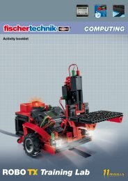
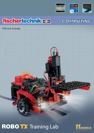
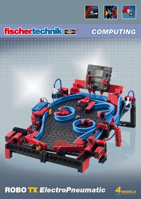
ROBO TX ElectroPneumatic<br />
Welcome to the fischertechnik Computing World 3<br />
About this Activity Booklet 3<br />
History 4<br />
Principles of pneumatics 4<br />
Producing motion with air 4<br />
Generating and storing compressed air – diaphragm pump as compressor 5<br />
Switching compressed air – solenoid valves 6<br />
Interaction of electrical and pneumatic circuits 6<br />
ROBO Pro control software 7<br />
ROBO TX Controller 7<br />
Compressed air motor 8<br />
Programming 9<br />
Color sorting robot 10<br />
Sensors 10<br />
Sensors and actuators 11<br />
Color recognition subprogram 12<br />
Ball obstacle course with vacuum picker arm 13<br />
Variables 14<br />
Pinball machine 15
COMPUTING<br />
Welcome to the fischertechnik Computing World<br />
Hello!<br />
3<br />
ROBO TX ElectroPneumatic<br />
Congratulations on your purchase of the ROBO TX ElectroPneumatic construction<br />
set from fischertechnik. We promise you that your interest will be<br />
rewarded. Because with this construction set you can conduct many interesting experiments<br />
and solve exciting tasks.<br />
This digital activity booklet accompanies you step for step as you try out your fischertechnik models. It<br />
contains important tips and valuable additional information for conversion and optimization. At the end<br />
you will be able to control and program various electro-pneumatic models with the ROBO TX Controller.<br />
We start with simpler things initially to ensure you have fun right from the very beginning. With the<br />
knowledge you gain you can then meet the challenge of the next task - and so forth - step for step.<br />
So don't be timid, we will plunge into the fischertechnik Computing World together and then go on to<br />
more complex tasks.<br />
Now we wish you a great deal of fun and success experimenting with the ROBO TX ElectroPneumatic<br />
set.<br />
Your team from<br />
About this Activity Booklet<br />
This PDF Activity booklet has a few features not present in the printed booklet. Most are similar to those<br />
you may already be familiar with from the Internet. But sometimes they can also do more.<br />
test only.rpp<br />
▯<br />
▯<br />
Purple text<br />
This shows you information on the term itself when you roll over it with the mouse.<br />
Underlined blue text:<br />
This actuates a function when clicked - for example starting the ROBO Pro help.<br />
▯ ROBO Pro Symbol:<br />
This is always located in the vicinity of tasks. This makes sense, because as soon as you click on it a suitable<br />
example program opens with a possible solution.<br />
All example programs are listed under C:\Programs\ROBOPro\Example programs\ROBO TX Electro-<br />
Pneumatic.
COMPUTING<br />
History<br />
EN<br />
Principles of pneumatics<br />
Industrial cylinder<br />
4<br />
ROBO TX ElectroPneumatic<br />
Compressed air is one of the oldest forms of energy. Nearly 2500 years ago soldiers<br />
built military equipment, which used compressed air to shoot projectiles such as balls<br />
or spears.<br />
Ctesibius from Alexandria in Egypt, (* 296 B.C. in Alexandria, † 228 B.C.), was a Greek<br />
engineer, inventor and mathematician, who lived during the first half of the third century<br />
before Christ and built weapons operated by compressed air.<br />
It is therefore no wonder that the word "Pneumatic“ was taken from the Greek word<br />
"pneuma“, which means "air“.<br />
The first compressor was a bellows. In blacksmith shops in the middle ages and far<br />
later, right up to today's modern industrial era, bellows have been used to increase the<br />
temperature of a fire.<br />
A<br />
Today pneumatics play an essential role in modern industry. Pneumatically driven machines<br />
and automation equipment can be found everywhere. For example, on assembly<br />
lines various parts are put together to form assemblies and the function is checked;<br />
goods are sorted and packed.<br />
Air can be used for different purposes in technology. For example wind drives gigantic<br />
windmills to generate electrical power. Pneumatics uses air to generate motion and<br />
transfer forces.<br />
You are certainly familiar with at least one pneumatic tool - the air pump for your<br />
bicycle tires. It is designed using the physical and technical principles of a cylinder, as<br />
introduced in this construction set, for example using a compressor to generate compressed<br />
air.<br />
Producing motion with air<br />
A number of pneumatic cylinders are included in the ElectroPneumatic construction<br />
set. You need one of them for the first experiment.<br />
Pneumatic cylinder from fischertechnik<br />
The piston rod with piston can<br />
move and is sealed along the cylinder<br />
wall by gaskets.<br />
If you blow air into the cylinder<br />
through connection A, the piston<br />
moves.<br />
Hose connection B<br />
(not used)<br />
Hose connection A<br />
Piston rod with<br />
piston and spring
COMPUTING<br />
Circuit diagram of single<br />
acting cylinder<br />
Pressure gage for<br />
measuring air pressure<br />
Compressor<br />
Circuit diagram of<br />
compressed air source<br />
5<br />
ROBO TX ElectroPneumatic<br />
The air moves this cylinder in one direction only. It is returned to its initial position by the force of a<br />
spring. Such cylinders are called "single acting cylinders".<br />
Note:<br />
The connection you use to move out (extend) the piston is designated "A"; the piston is pulled back (retracted)<br />
with the aid of a spring.<br />
Air can be compressed<br />
Anyone working with pneumatic equipment today should know something about the physical properties<br />
of air. You can use a little test for this purpose:<br />
Pull the red piston rod in the cylinder all the way out. Then hold connection A shut with your finger.<br />
Now release the piston rod. What can you observe?<br />
The piston rod is pulled back only a short distance by the spring.<br />
Result:<br />
The air in the cylinder is pressed together (compressed) preventing the piston rod from moving. The<br />
more air compressed, the greater the air pressure in the cylinder. This pressure can be measured with a<br />
pressure gage or also calculated. The unit of measure for pressure is ”bars” or ”Pascals”<br />
You can remember the following equation for this:<br />
Pressure = force/area or p = F/A<br />
From this equation you can see that the pressure depends on the force exerted on a round surface in the<br />
cylinder.<br />
Generating and storing compressed air – diaphragm pump as compressor<br />
The diaphragm pump included in the construction set supplies the compressed air required for you to<br />
control the individual models. In industrial circles this is known as the compressed air source.<br />
Mode of operation:<br />
A diaphragm pump consists of two chambers<br />
separated by a diaphragm (membrane). In one<br />
chamber the resilient diaphragm is moved up<br />
and down by a piston or cam. During the downward<br />
stroke the diaphragm is pulled back and<br />
air is pulled into the second chamber through<br />
the inlet valve. When the piston moves up, the<br />
diaphragm presses the air out of the pump head<br />
through the outlet valve.<br />
Note:<br />
Inlet/outlet valve<br />
Diaphragm<br />
Cover<br />
Piston<br />
Cylinder<br />
Crank drive<br />
The pressure generated by the compressor is approx. 0.7 to 0.8 bars. The diaphragm pump is maintenance-free.
COMPUTING<br />
(3)<br />
(1)<br />
3/2-way valve<br />
P<br />
R<br />
P<br />
R<br />
(2)<br />
Circuit diagram of a 3/2-way valve<br />
A<br />
A<br />
6<br />
ROBO TX ElectroPneumatic<br />
Switching compressed air – solenoid valves<br />
In pneumatics the purpose of a valve is to control the flow of air to the pneumatic cylinder<br />
so that the cylinder either extends or retracts. The valve can be actuated either by<br />
hand, pneumatically or electromagnetically as on your technical models.<br />
Technical data on valve: 3/2-way valve, 9V DC/130 mA<br />
3/2-way means that the valve has three connections and two switching states.<br />
Note:<br />
When connecting the valve to the power source or to the ROBO TX Controller ensure<br />
that the polarity is correct.<br />
Brief technical explanation:<br />
Applying a voltage to the coil (1) creates a magnetic field which pulls down core (2).<br />
The valve opens and the air flows from connection "P" through connection "A" to the<br />
cylinder. When voltage is not applied, the core is pressed upward by the spring (3) and<br />
the valve is closed.<br />
When the valve is closed, connection "A" is connected to the vent "R". This is important,<br />
to allow the air to escape from the cylinder.<br />
The connections are always designated as follows in pneumatics:<br />
P = Compressed air connection<br />
A = Connection to cylinder<br />
R = Vent<br />
Interaction of electrical and pneumatic circuits<br />
Task:<br />
Actuate a solenoid valve to extend a single acting cylinder. The cylinder should<br />
extend when the operator closes a switch. As long as the switch is closed, the<br />
cylinder should remain extended. When the switch is returned to the initial position,<br />
the pressure of the spring should cause the cylinder to retract.<br />
Engineers frequently use symbols to show such tasks. One circuit diagram shows the<br />
electrical part and one the pneumatic part or stage.
+9V<br />
V1<br />
0V<br />
COMPUTING<br />
+9V<br />
T1<br />
0V<br />
V1<br />
V1<br />
A1<br />
A<br />
P R<br />
Circuit diagram - electrical, pneumatic stage<br />
T1<br />
V1<br />
A1<br />
Circuit diagram - non-actuated position<br />
7<br />
ROBO TX ElectroPneumatic<br />
In the illustration the electrical part is on the left and the pneumatic stage on the right.<br />
The electrical part consists of a +9V power source, a pushbutton and the valve coil<br />
(electromagnet). The pneumatic stage consists of the compressed air source, the valve<br />
and the cylinder.<br />
Note:<br />
Since the magnetic coil and valve form one unit, they are shown using the same symbol.<br />
This clearly shows that the coil and valve belong together.<br />
The two figures below show the circuit in the non-actuated state, in the figure on the<br />
right with the button pressed. The figure on the right clearly shows the flow of electricity<br />
as well as air.<br />
ROBO Pro control software<br />
Control logic with ROBO Pro software and ROBO TX Controller<br />
Program example with<br />
symbolic commands<br />
A<br />
P R<br />
In addition to its mechanical construction, the unit requires the control logic, software<br />
for the PC and an interface ( ROBO TX Controller) to convert the software commands<br />
into signals which the machine can execute.<br />
The ROBO Pro control software has a simple graphical programming interface which<br />
allows you to create programs without having to learn a programming language.<br />
For the ROBO TX ElectroPneumatic construction set you need ROBO Pro version<br />
3.1.3 or higher. If you have an older version of the software, it will be automatically<br />
updated when you install the ROBO TX ElectroPneumatic CD.<br />
ROBO TX Controller<br />
The ROBO TX Controller is the most important component in the model. It controls<br />
the actuators (motors, lights & valves) and evaluates information from the sensors.<br />
For this purpose the ROBO TX Controller has numerous connections<br />
for connection to the components. The instruction manual for the ROBO<br />
TX Controller describes which components can be connected to which connections<br />
and the functions of the connections.<br />
+9V<br />
V1<br />
0V<br />
T1<br />
A special feature is the integrated Bluetooth interface. It allows you to complete a<br />
wireless link between your PC and the ROBO TX Controller. Or to connect a number<br />
of controllers with one another. You can define how the controller interacts with the<br />
individual components and what they are to do in detail in the program you write with the ROBO Pro<br />
software.<br />
V1<br />
Circuit diagram - button pressed<br />
A1<br />
A<br />
P R
COMPUTING<br />
Compressed air motor<br />
3/2-way valve<br />
Pneumatic cylinder<br />
Pushbutton<br />
Switching plate<br />
For your first model, build the "compressed air motor" as<br />
described in the assembly instructions. A compressed air<br />
or pneumatic motor functions similar to a steam<br />
engine. It has a cylinder, a piston, an intake and<br />
an outlet. However, compressed air serves as the<br />
"propellant" instead of hot steam. For the first task install<br />
the button so that you can press it with your hand.<br />
Technical information on pushbutton.<br />
8<br />
ROBO TX ElectroPneumatic<br />
The pushbutton has three connections or terminals. Depending on the application you can use the pushbutton<br />
....<br />
... as a "normally open switch":<br />
By connecting terminals 1 and 3.<br />
When the pushbutton is pressed: Electricity flows.<br />
When the pushbutton is not pressed: Electricity does not flow<br />
... or as a "normally closed switch":<br />
By connecting terminals 1 and 2.<br />
When the pushbutton is pressed: No electricity flows.<br />
When the pushbutton is not pressed: Electricity flows.<br />
Wire the electrical components as described in the assembly instructions in circuit diagram A.<br />
Task 1: Manual control with pushbutton.<br />
Press the button and observe the model. What makes the wheel turn and how?<br />
As you can see, each time you press the button the solenoid valve switches and the cylinder extends.<br />
This causes the wheel to rotate half a turn. When you release the button, the wheel rotates another half<br />
turn. This is accomplished by the return spring in the pneumatic cylinder.<br />
Task 2: Control with switching plate.<br />
Turn the pushbutton to the installation position specified. Instead of pressing the button manually, it<br />
is now actuated by a switching plate. How will this affect the model?<br />
Switching plate<br />
Pushbutton<br />
It is necessary to switch the valve on and off at the right time.<br />
Then the wheel will rotate continuously.<br />
Important! Adjust the switching plate so that the pushbutton<br />
switches the valve exactly when the crank is in the top-most<br />
or bottom-most position.<br />
For the next task install the ROBO TX Controller in the model<br />
and wire the electrical components as described in circuit B in<br />
the assembly instructions.<br />
3<br />
2<br />
3<br />
2<br />
1<br />
1
COMPUTING<br />
Programming<br />
New program<br />
Important! You can get help<br />
under the menu point<br />
or by clicking the right mouse<br />
button on the program element<br />
in the "Element window"<br />
Task 3: Testing the model with the ROBO TX Controller<br />
9<br />
ROBO TX ElectroPneumatic<br />
Connect the ROBO TX Controller to the power supply and switch it on. Connect<br />
the ROBO LT Controller to the PC. Then start the ROBO Pro software.<br />
Activate the "Test" button. The operating display appears to test the controller<br />
and the connected sensors and actuators. Click with the mouse pointer<br />
on Output M1 - right and then Output M2 - right. Observe what happens at Input<br />
I1.<br />
The compressor at Output M1 starts running and produces compressed air for the cylinder.<br />
If M2 is switched on, the solenoid valve is actuated and the piston in the cylinder<br />
extends. At Input I1 a check set when the connected pushbutton is closed.<br />
Task 4: Program control with ROBO Pro - Level 1<br />
ROBO TX Controller takes over actions in task 3 using program. Here the<br />
switching state of pushbutton (I1) is checked and the information, "closed/<br />
open" used to control the valve and cylinder.<br />
The operating display can be cleared with the "New"<br />
button. In the "Level" selection window switch to level<br />
1.<br />
All the commands required for this task are present in<br />
the "Element group" selection window. However the<br />
ROBO Pro help is also very valuable here.<br />
Each program always starts with the "Little green<br />
traffic light man". Then the individual program commands such as "Motor on" or "Time<br />
delay" can be entered. The symbols can be moved to the operating display with the<br />
mouse using the drag and drop feature. Information on the commands used is given in<br />
ROBO Pro help Chapter 3.<br />
Use the program from the following program structure:<br />
Click with the right<br />
mouse button on the<br />
desired symbol; an interactive<br />
window appears<br />
in which you can make<br />
various settings, e.g. set<br />
the time, actuator, etc.<br />
You can call a finished example program for this task with this symbol.<br />
compressed air motor.rpp
COMPUTING<br />
Start program in online<br />
mode<br />
Stop<br />
all programs in progress<br />
Download program for ROBO TX Controller<br />
Color sorting robot<br />
Sensors<br />
10<br />
ROBO TX ElectroPneumatic<br />
After finishing the program, you can start it with the button "Start program in online<br />
mode". The individual program steps are then performed. Since you have programmed<br />
a continuous loop, it is also necessary to stop it, when you are finished. For this purpose<br />
use the button "Stop all running programs".<br />
It may be necessary to readjust the switching plate when operating the compressed air<br />
motor with the ROBO TX Controller, to get the motor to run "smoothly". You can do this<br />
by trial and error.<br />
It is possible to transfer the program to the ROBO TX Controller. This can be accomplished<br />
with the "Download" button. The interactive window appears to enter the various<br />
parameters.<br />
Start program: The program can be started immediately after<br />
transfer or after pressing a button. Information is given in<br />
ROBO Pro help Chapter 3.7.<br />
The color sorting robot model is<br />
designed to sort parts automatically<br />
according to their color. Build<br />
the model according to the assembly<br />
instructions and wire the electrical and<br />
pneumatic components according to the circuit<br />
diagram. During assembly pay attention to accuracy when<br />
installing the parts, connecting the hoses and wiring the electrical<br />
components. This eliminates the need for trouble-shooting when you put the model<br />
into operation.<br />
With this model you become familiar with new components such as those used in<br />
industrial equipment. This includes the vacuum picker arm with suction cup, the twocylinder<br />
vacuum generator, the optical color sensor and the light barrier with phototransistor<br />
and light source.<br />
Optical color sensor<br />
Color sensors are used frequently in automation technology. This is done, for example,<br />
to examine the color or the color imprint to ensure that the correct components are<br />
installed. The fischertechnik color sensor transmits red light, which is reflected with<br />
different strength from different colored surfaces. The quantity of reflected light is<br />
measured by the phototransistor and output as a voltage between 0 V and 10 V. A type<br />
of "darkroom" is built into the sensor in this model to prevent excessive light scatter. An<br />
opening is provided for the sensor. The part to be measured can be positioned on top<br />
of this opening.
COMPUTING<br />
Color Value<br />
White<br />
Red<br />
Blue<br />
Phototransistor<br />
(sensor)<br />
Light barrier<br />
+<br />
Bellows suction cup<br />
fischertechnik suction cup<br />
Suction cup circuit diagram<br />
Sensors and actuators<br />
Lamp<br />
(actuator)<br />
11<br />
ROBO TX ElectroPneumatic<br />
Connect the color sensor to I3 using with the black and green cable and to + with the<br />
red cable (see circuit diagram in assembly instructions).<br />
Task 1 - Defining color values:<br />
First check the values output by the ROBO TX Controller for the parts in the interface<br />
test (white, red, blue). Use the interface test in ROBO Pro for this purpose.<br />
Set input I3, connected to the color sensor, to analog 10V (color sensor).<br />
Make a small table and enter the values you have measured. Also observe the changes<br />
when the distance to the colored surface or the ambient light changes.<br />
In addition a light barrier is used for the next task. This consists of a light-sensitive sensor<br />
(phototransistor) and a lens tip lamp (actuator) as light source.<br />
Phototransistor<br />
You can also call the phototransistor a "brightness sensor." This is a "sensor" that reacts<br />
to brightness. In a light barrier it is the counter-part of the lens tip lamp. When there<br />
is a high degree of brightness, that is when the transistor receives light from the lens<br />
tip lamp, it conducts electricity. If the light beam is interrupted, the transistor does not<br />
conduct any electricity. Caution! Pay attention to the polarity when connecting the<br />
phototransistor to the power supply. Red = positive.<br />
Lens tip lamp<br />
This is an incandescent bulb with built-in lens to focus the light. It is required to build a<br />
light barrier. The lens tip lamp can be recognized by its gray base.<br />
Electric motor<br />
The direct current motor converts electrical energy into mechanical energy. This results<br />
in the rotational movement of the motor. A motor also has a gearbox. With this gearbox<br />
you can reduce the speed of the motor and simultaneously increase the torque (motor<br />
pulling force).<br />
Vacuum pump<br />
You need a vacuum pump for the model to produce<br />
the vacuum to pick up the parts. Since the<br />
vacuum pumps used for industrial applications are<br />
very expensive, you can use a simpler solution for<br />
producing a vacuum. You need two cylinders with<br />
connected piston rods. Connect connection A to<br />
the compressor over the solenoid valve. Connection<br />
B leads to the suction cup. When the valve<br />
is actuated, both pistons are pushed forward. If<br />
the suction cup is positioned on a part, the air is<br />
sucked in by the two pistons producing a vacuum.<br />
The bellows type suction cup has a lifting function and can be used on flat as well as<br />
slightly arched surfaces.<br />
B<br />
A
COMPUTING<br />
Start compressor and lamp<br />
Button connect to C1 as pulse counter<br />
Tip:<br />
Task 2 - Control program - ROBO Pro Level 2<br />
12<br />
ROBO TX ElectroPneumatic<br />
A light barrier is located at the end of the chute to recognize whether a part is present.<br />
If so, the gripper arm picks up the part and places it on the color sensor for<br />
recognition of the color. The sensor determines the color.<br />
The part is then placed in the proper box.<br />
Box 1 = white, Box 2 = red and Box 3 = blue.<br />
For programming consider the sorting sequence. Here is a little help:<br />
▯<br />
▯<br />
▯<br />
▯<br />
▯<br />
▯<br />
▯<br />
▯<br />
Compressor switches on - Output O3 also for lens tip lamp<br />
Model starts after pressure builds up<br />
The robot arm turns until limit switch I1 is switched; motor turns: counterclockwise<br />
Light barrier check - is part present?<br />
Part picked up and transported to color recognition - pulse counter check C1D<br />
Color checked by color sensor I3<br />
Continued transport and separation according to color - pulse counter C1D<br />
Return to check light barrier - limit switch I1<br />
You can call a finished example program for this task with this symbol.<br />
Color recognition subprogram<br />
In addition to the main program you can also create subprograms in ROBO Pro. These<br />
serve to keep your program structure clear - once written, subprograms can also be<br />
copied into other applications.<br />
Subprogram<br />
Input subprogram<br />
Output subprogram<br />
Color recognition subprogram<br />
Symbol for color recognition<br />
subprogram<br />
Information on what subprograms are and how they can be used is given in the<br />
ROBO Pro help in Chapter 4. It is important that you switch to level 2 or higher in ROBO<br />
Pro.<br />
The "color recognition" subprogram provides an example. As defined in the task, the<br />
color is to be recognized and the part then stored according to color. The jump to the<br />
"color recognition" subprogram is shown by a green box in the main program.<br />
Important! To incorporate a subprogram into a main program,<br />
it is first necessary to write the subprogram.<br />
It may be necessary to adapt the values in the color recognition<br />
subprogram to the values you determined in task 1, so<br />
that the color recognition functions properly.<br />
color sorting robot.rpp
COMPUTING<br />
Ball obstacle course<br />
with vacuum picker arm<br />
P2<br />
With this model the vacuum picker arm automatically<br />
returns balls from the end to the start of an<br />
obstacle course. Build the model according to<br />
the assembly instructions and wire the electrical<br />
and pneumatic components according to the<br />
circuit diagram. During assembly pay attention to<br />
accuracy when installing the parts, connecting the hoses<br />
and wiring the electrical components. This eliminates the need for<br />
trouble-shooting when you put the model into operation.<br />
Tips<br />
Task 1 - Return a ball - ROBO Pro Level 2<br />
13<br />
ROBO TX ElectroPneumatic<br />
A ball is to be returned at one of the two ends of obstacle course P1 or P2 by the<br />
vacuum picker arm. The two light barriers are checked to determine where the ball<br />
is located. After picking up, the ball is transported to position 3 on the obstacle<br />
course and put down. The ball rolls to the gate where it is guided to one of<br />
the two final paths. The program is intended to run as a continuous loop.<br />
As with the previous programming tasks, it is necessary to consider the sequence you want. Also consider<br />
which parts of the program will need to be written in a subprogram.<br />
▯<br />
▯<br />
▯<br />
▯<br />
▯<br />
▯<br />
P1<br />
Ends of obstacle courses<br />
Switch on the compressor and lens tip lamps for the light barriers (2 sec. time delay)<br />
Start the model and position the robot arm at the start position - Check sensor I1, motor direction of<br />
rotation: Counterclockwise<br />
Check the two light barriers<br />
Pick up the balls<br />
Transport to set-down location P3 and set down balls - pulse counter<br />
Return to light barrier check to see if new balls are present<br />
You can call a finished example program for this task with this symbol.<br />
Task 2 - Both obstacle courses - ROBO Pro Level 2<br />
The light barrier check tells the robot where a ball is located so that the robot can transport the ball<br />
to the start of the track. If the ball is at the end of the front track (P1), it should be put down at<br />
position P3. If the ball is at the end of the rear track (P2), it should be put down at position P4.<br />
P2<br />
You can call a finished example program for this task with this symbol.<br />
P3<br />
P1<br />
P4<br />
ball obstacle course_1.rpp<br />
ball obstacle course_2.rpp
COMPUTING<br />
Tips<br />
14<br />
ROBO TX ElectroPneumatic<br />
The position of the gripper arm can be defined with the aid of the "pulse counter" command. The values<br />
required can be entered in the interactive window.<br />
If the ideal position is between two pulses, you can also adjust the start or end position of the balls by<br />
moving one or more of the building blocks so that the gripper picks up or puts down the ball reliably.<br />
Information on the commands used is given in ROBO Pro help Chapters 3. and 8.1.10.<br />
Variables<br />
Task 3 - Two balls in obstacle course - ROBO Pro Level 3<br />
Now two balls roll through the obstacle course. Two conditions should be fulfilled to ensure that the<br />
robot distributes the balls uniformly on the two tracks:<br />
•<br />
•<br />
Balls arriving at the bottom end points (P1 or P2) should be transported alternately to the upper<br />
starting points (P3 or P4).<br />
If balls are present simultaneously at both end points (P1 and P2), they should also be<br />
picked up alternately.<br />
You can meet these requirements by supplementing the program.<br />
Tips<br />
So-called variables help to solve this problem. Information on what variables are and how they can be<br />
used is given in the ROBO Pro help in Chapter 5. It is important that you switch to level 3 in ROBO Pro.<br />
Here is the solution:<br />
Define a variable (Pos1 – Pos4) for each of the 4 positions P1, P2, P3 and P4. When a position is reached,<br />
set the value for the associated variable to 1 to help you remember the position moved to last.<br />
Example:<br />
First ball: Variable Value Variable Value<br />
Ball present at P1 Pos1 = 1 Pos2 = 0<br />
Ball moved to P3 Pos3 = 1 Pos4 = 0<br />
Second ball:<br />
Ball present at P1 and P2. Since Pos1=1, the robot should now go to P2. Then Pos1 is set to 0 and Pos2<br />
to 1. Since the ball was set down at P3 during the first operation (Pos3 = 1), the ball is now transported<br />
to P4. Then Pos1 is set to 0 and Pos2 to 1.<br />
Too complicated? You can call a finished example program for this task with this symbol.<br />
Attempt to understand how the principle works by looking at the final sequence.<br />
ball obstacle course_3.rpp
COMPUTING<br />
Pinball machine<br />
Cylinder as air reservoir<br />
Ball launching pad<br />
Light barrier for detecting passage<br />
Now you can play pinball!<br />
Build the model according to the assembly<br />
instructions and wire the electrical and pneumatic<br />
components according to the circuit<br />
diagram. During assembly pay attention<br />
to accuracy when installing the parts,<br />
connecting the hoses and wiring the<br />
electrical components. This eliminates<br />
the need for trouble-shooting when you<br />
put the model into operation.<br />
15<br />
ROBO TX ElectroPneumatic<br />
l Before starting to program the model, here is further technical information on the<br />
cylinder below the model as well as additional actuators and sensors. The cylinder is<br />
used as a storage reservoir for air, to ensure that enough air is available to move the<br />
cylinders when the flipper buttons are pressed quickly one after the other.<br />
l The ball can be shot into the playing field by a spring mechanism on the right side of<br />
the model. This works according to the same principle as a real pinball machine.<br />
l The two buttons at the left and right lower<br />
edges serve for electrical control of the two<br />
valves for the built-in cylinders. These control the<br />
two flipper arms. A light barrier detects when a<br />
ball drops through the middle gap or runs past<br />
an incorrectly positioned flipper arm. This light<br />
barrier also serves later for counting the balls<br />
planned for one game.<br />
l Another light barrier and the color sensor serve<br />
to keep the score . The light barrier records when<br />
the ball passes through and the color sensor measures<br />
the distance between the color sensor and<br />
ball. This is explained in greater detail later in the<br />
program explanation.<br />
l The ROBO TX Controller display serves to<br />
indicate the score and number of balls remaining.<br />
The display can be controlled with the two red<br />
buttons.<br />
Pinball control<br />
Color sensor for proximity measurement<br />
Measured value logging and output
COMPUTING<br />
TX display program call<br />
Defined TX display<br />
TX display element group<br />
Control panel input<br />
Task 1 - Pinball control program - ROBO Pro Level 3<br />
16<br />
ROBO TX ElectroPneumatic<br />
A ball is shot into the game field from a launching pad. The ball then runs through<br />
the obstacle course set up. When it passes the light barrier or comes close to the<br />
color sensor, points are given. The points are shown on the TX display. Every<br />
player has three balls. The round is completed when all balls have been<br />
played. The game can be started again by pressing the red button on the<br />
left (OK button).<br />
You already know all the commands required for this task. New is the fact that the data<br />
is shown on the ROBO TX Controller display.<br />
You can call a finished example program for this task with the symbol.<br />
Information on the commands and how they can be used is given in the<br />
ROBO Pro help in Chapters 9 and 11.<br />
Tip:<br />
For programming consider the game sequence. Here is a little help:<br />
▯<br />
▯<br />
▯<br />
▯<br />
▯<br />
▯<br />
▯<br />
▯<br />
Switch on compressor 03 - light outputs O6 and O7 (for light barriers)<br />
Shoot in ball - manually<br />
Check flipper buttons I1 left and I2 right, actuate valves at 04 and 05<br />
Check and evaluate color sensor at I8<br />
Check and evaluate light barriers at I3 and I4<br />
Output points earned and balls played on display<br />
End of game, reset outputs 03, 06, and 07 to zero<br />
Start new game with OK button (right display button)<br />
The "Count balls" subprogram illustrated is intended to show you the interrelationship<br />
between the program and the TX display.<br />
At the start of the game the value 3 appears on the display<br />
indicating that 3 balls are available. When the light barrier at I4<br />
detects a ball, the value shown on the display is reduced by 1.<br />
After all balls have been played, the display indicates zero. The<br />
game is finished.<br />
If you want to stop the program loaded on the TX controller<br />
completely, it is necessary to press both display buttons simultaneously.<br />
pinball machine.rpp
COMPUTING<br />
Keeping score:<br />
17<br />
ROBO TX ElectroPneumatic<br />
You can use various systems to assign points. In the program used as an example the program waits 5<br />
seconds after the light barrier is interrupted for the first time and simultaneously counts how many times<br />
the light barrier is interrupted during this time. The more times you quickly shoot the ball through the<br />
light barrier, the more points you get.<br />
Light barrier subprogram<br />
The color sensor allows you to get more points, when the ball passes closer to the sensor.<br />
Do you have any other ideas? Use your imagination.<br />
Enjoy programming and playing with your pinball machine.<br />
Your team from