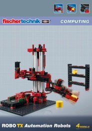
computing - Fischertechnik
computing - Fischertechnik
computing - Fischertechnik

You also want an ePaper? Increase the reach of your titles
YUMPU automatically turns print PDFs into web optimized ePapers that Google loves.
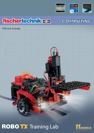
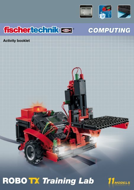
Activity booklet<br />
Training Lab<br />
COMPUTING
COMPUTING<br />
Contents<br />
2<br />
ROBO TX Training Lab<br />
Welcome to the ROBO TX Training Lab 3<br />
Some General Information 3<br />
Electricity 3<br />
About this Activity Booklet 3<br />
The robot, the artificial human being? 4<br />
Computing, (Almost) Everything Automatic 4<br />
Component Explanations 4<br />
Encoder Motors 5<br />
XS Motor 5<br />
Bulb 5<br />
Lens Tip Lamp 5<br />
Phototransistor 5<br />
Trail Sensor 6<br />
Pushbutton 6<br />
Heat Sensor (NTC) 6<br />
A Few Tips 7<br />
First Steps 7<br />
Starter Models 8<br />
The Hand Dryer 8<br />
The Traffic Light 9<br />
The Elevator 10<br />
The Rinsing-Drying Machine 10<br />
Temperature Control 11<br />
Robots -- The Next Challenge 12<br />
Basic Model 12<br />
The Trail Searcher 13<br />
The Lawn Mower 14<br />
The Soccer Robot 15<br />
The Measuring Robot 16<br />
The Forklift 17<br />
If it doesn’t work right away . . . 19<br />
And what else is there to do? 20
COMPUTING<br />
Welcome to the ROBO TX Training Lab<br />
3<br />
ROBO TX Training Lab<br />
Hello!<br />
We are happy that you have chosen the construction set "ROBO TX Training<br />
Lab" from fischertechnik. And we promise you that your interest will be rewarded.<br />
This is because with this construction set you can conduct a lot of interesting<br />
experiments and solve exciting tasks.<br />
When you read this screen booklet and try the experiments and tasks, you will<br />
learn step-by-step how you can control and program simple and also complicated<br />
machines and robots using the ROBO TX Controller from fischertechnik.<br />
Since learning is just this way, you can't immediately start with the most difficult things even if they are naturally<br />
often a little bit more interesting than the somewhat more simple ones. This is why we have structured the experiments<br />
and tasks in this booklet so that you learn something different with every new task and can then use this for<br />
the next task.<br />
So don't worry, we start with small things and then we work together to progress to the big robots.<br />
We hope you have a lot of fun and success now with the experimentation with the ROBO TX Training Lab.<br />
Your team from<br />
fischertechnik<br />
Some General Information<br />
Before we really get started with the construction set, you still need to know a few things. The components, which<br />
we will work with, are of course very robust, but if you don't handle them correctly, they can be damaged under<br />
certain circumstances.<br />
Electricity<br />
As you certainly know, a lot of the components in the ROBO TX Training Lab use electric power. And for things,<br />
which have to do with electricity, you must be particularly careful not to make any mistakes. That is why you should<br />
always read the assembly instructions very carefully when wiring the electrical components.<br />
Do not connect the positive and negative poles with each other in any case, which means do not short-circuit. If this<br />
is done then this can damage the ROBO TX Controller or even the rechargeable battery.<br />
Electricity and electronics are just as interesting topics as is robotics (which is just what this construction set is<br />
about) and there is a construction set from fischertechnik, which deals with these subjects in particular. So if you are<br />
interested in this then you will also have just as much fun with the "PROFI E-Tech" construction set as with the<br />
ROBO TX Training Lab.<br />
About this Activity Booklet<br />
This pdf activity booklet has a few functions, which you do not find in a printed booklet and which you may already<br />
know from the Internet.<br />
Links within the Booklet<br />
When something is mentioned somewhere in the text, which is explained in more detail at another point in this<br />
booklet (for example, components), then this text is in dark blue and underlined. You can click on the text and thus<br />
move automatically to the page, which contains the explanation. This is called a "cross reference."<br />
Background Infos<br />
In some cases in this booklet, there are terms or foreign words, which may require explanation. These terms are in<br />
green and underlined. If you touch the text with the mouse pointer then a field appears with an explanation.
COMPUTING<br />
4<br />
ROBO TX Training Lab<br />
Link Outside of this Booklet<br />
You need an Internet connection for a few links (for example, for the fischertechnik Web site), or an installed ROBO<br />
Pro (for connection to the ROBO Pro online help). These links are in bright blue and underlined.<br />
Pictures<br />
A picture is worth a 1000 words. You have certainly heard this sentence already. And because this certainly contains<br />
a lot of truth, you can display a picture by touching the words in brown and are underlined and the picture shows you<br />
what is meant in the text.<br />
The robot, the artificial human being?<br />
What do you first think about when you hear the word "robot"? Have you ever seen a robot?<br />
In a movie or on television? Or perhaps a real one?<br />
There are innumerable different types of robots. Some robots look a bit like a<br />
human, but others only consist of one or several arms. So, what exactly makes a<br />
robot a robot?<br />
The dictionary states: "Robots are stationary or mobile machines, which perform<br />
set tasks according to a certain program."<br />
Computing, (Almost) Everything Automatic<br />
Thus, robots are machines, which are controlled by a program. And we call this<br />
control of machines (or in our case models) "<strong>computing</strong>."<br />
The "ROBO TX Training Lab" provides you with a wonderful start to learn about this subject. This is because the construction<br />
set contains everything that you need to build and control many different machines.<br />
You can create the programs for the control of the models on a PC with the help of the software, ROBO Pro, and then<br />
transfer them to the ROBO TX Controller using the USB or Bluetooth connection. The Controller then "controls" and<br />
steers the model according to the programing, which you have prepared.<br />
Component Explanations<br />
The Construction Set Contains All of This<br />
First, you will find several fischertechnik building blocks, as well as motors, indicator lights and sensors and colored<br />
assembly instructions for the building of various models.<br />
After you have unpacked all of the building blocks, you have to assemble some components first such as cables and<br />
plugs before you can really get started. The exact ones are described in the assembly instructions under "Assembly<br />
Tips.” It is best to do this first.<br />
Actuators<br />
Actuators are all components, which can perform an action. This means that they become<br />
"active" in some form when they are connected to electric power. In most cases you can see<br />
this directly. A motor runs, an indicator light is illuminated and so forth.
COMPUTING<br />
Encoder Motors<br />
5<br />
ROBO TX Training Lab<br />
We use the two encoder motors, which are contained in the construction set, as the drive for our robots. At first<br />
glance, these are normal electric motors, which are designed for a voltage of nine volts and current input of a maximum<br />
of 0.5 amperes.<br />
But the encoder motors can do still more: In addition to the connection for the power supply for the motor, they have<br />
another jack socket for a three-pin connection cable and through this and with the aid of what is called the encoder,<br />
the rotational movement of the motor can be evaluated.<br />
The encoder functions similar to the speedometer on a bicycle. A magnet (in most cases for a bicycle located on one<br />
of the spokes) passes by a sensor (attached to the fork of the bicycle in most cases) with each revolution and the<br />
sensor generates a pulse due to this. These pulses can be counted, and, for example, multiplied with the circumference<br />
of the tire for the speedometer. In this way, the distance traveled is obtained.<br />
The encoders on the fischertechnik encoder motors generate three pulses with each revolution of the motor shaft.<br />
And because the encoder motors also have a gearbox with a transmission ratio of 25:1 (meaning "25 to 1"), then<br />
one revolution of the shaft, which comes out of the gearbox, corresponds to 75 pulses of the encoder.<br />
XS Motor<br />
The XS motor is an electric motor, which is exactly as long and high as a fischertechnik building block. In addition, it<br />
is very light. Due to this, you can install it at points, which do not have enough space for the big motors.<br />
Both gearboxes, which are also included in the construction set, fit exactly on the XS motor.<br />
The XS motor is designed for a supply voltage of nine volts and a current consumption of a maximum of 0.3<br />
amperes.<br />
Bulb<br />
Two bulbs are contained in the construction set. They can be used very multifariously, for example, as signal lights<br />
for a traffic light or as a blinking light on a robot.<br />
The bulbs are designed for a voltage of nine volts and consume about 0.1 amperes of current.<br />
Lens Tip Lamp<br />
A lens is a part of this lamp and this focuses the light. It looks very similar to the bulb lamp. You must be careful that<br />
you don't mistake one for the other. To make it easier to see the difference, the plug base for this lamp is gray, but the<br />
bulb lamp has a white plug base. You need the lens tip lamp to build a light barrier.<br />
The lens tip lamp is, as are the bulbs, designed for a voltage of nine volts and consumes about 0.15 amperes of<br />
current.<br />
Sensors<br />
Sensors are so to speak the counterpart to the actuators. This is because they do not perform any actions, but react<br />
to certain situations and events. For example, a pushbutton, reacts to the "pushing of the button" by allowing an<br />
electric current to pass or by interrupting it. A heat sensor reacts to the temperature in its surroundings.<br />
Phototransistor<br />
You can also call the phototransistor a "brightness sensor." This is a "sensor" that reacts to brightness.<br />
For a light barrier, this is the counterpart to the lens tip lamp. When there is a high degree of brightness, that is when<br />
the transistor receives light from the lens tip lamp, it conducts electricity. If the light beam is interrupted, the transistor<br />
does not conduct any electricity.<br />
Caution!<br />
When connecting the phototransistor to the power supply, you must pay special attention to the right polarity.<br />
The positive pole must be connected to the red marking on the phototransistor.
COMPUTING<br />
Trail Sensor<br />
6<br />
ROBO TX Training Lab<br />
The infrared trail sensor is a digital sensor for the identification of a black trail on a white background with a distance<br />
of five to 30 mm. It consists of two transmission and receiver elements. For connection, you need two digital inputs<br />
and the nine volt voltage supply (positive and negative pole) on the ROBO TX Controller.<br />
Pushbutton<br />
The pushbutton is also called a touch sensor. When you press the red button, this mechanically throws a switch and<br />
electricity flows between the contacts 1 (center contact) and 3. At the same time, the contact between the connections<br />
1 and 2 is interrupted. So you can use the pushbutton in two different ways:<br />
As a "closer"<br />
Contacts 1 and 3 are connected.<br />
Press the pushbutton: electricity flows.<br />
When the pushbutton is not pressed: no electricity flows.<br />
As a "break contact"<br />
Contacts 1 and 2 are connected.<br />
Press the pushbutton: no electricity flows.<br />
When the pushbutton is not pressed: electricity flows.<br />
Heat Sensor (NTC)<br />
This component is a heat sensor that you can use to measure the temperatures. At 20°C, its electrical resistance<br />
is 1.5kΩ (kiloohms). NTC stands for Negative Temperature Coefficient. This simply means that the resistance value<br />
decreases when the temperature increases.<br />
The information, which the sensors provide us, for example, bright-dark, pressed-not pressed and temperature value,<br />
can, as we will see later, be transmitted through the ROBO TX Controller to a PC and then with the help of the software,<br />
for example, be used to program a motor in such a way that a ventilating fan blows as soon as a light barrier is<br />
interrupted.<br />
Software ROBO Pro 2.x<br />
ROBO Pro is a graphic programing interface, with which you can create the programs<br />
for the ROBO TX Controller.<br />
"Graphic programing interface" means that you don't have to "write" the programs<br />
line for line by hand, but that you can simply compile them visually with the help<br />
of graphic symbols. You can find an example for such a program in the picture to<br />
the right.<br />
How you can precisely create such a program is described in detail in the ROBO<br />
Pro online help in chapters 3 and 4.<br />
The installation of ROBO Pro and the driver for the ROBO TX Controller is<br />
described in the installation instructions, which are contained in the construction<br />
set.<br />
The software is on the same CD as this activity booklet.<br />
When you are finished with the installation of ROBO Pro, you can then start ROBO<br />
Pro right away because the next thing we need is the online help of the software.<br />
The best thing for you to do now is to read through the first two chapters of the<br />
ROBO Pro online help. When you do this, you learn a little bit about the software<br />
at the same time so that following this we can start directly with the experimentation.<br />
3<br />
2<br />
1
COMPUTING<br />
A Few Tips<br />
First Steps<br />
ROBO TX Controller<br />
7<br />
ROBO TX Training Lab<br />
The ROBO TX Controller is the heart of this <strong>computing</strong> construction set. This is because it controls the actuators and<br />
evaluates the information from the sensors.<br />
For this task, the ROBO TX Controller has numerous connections, to which you can connect the components. What<br />
components can be connected to what connections and what the functions of the connections are are described in<br />
the instruction manual for the ROBO TX Controller.<br />
A special treat is the integrated Bluetooth interface. Using this, you can connect your PC to the ROBO TX Controller<br />
without a cable. Or you can also connect several Controllers with a PC and with each other.<br />
You determine how the Controller handles the individual components and what these are to do in detail with the<br />
program, which you write in the software ROBO Pro.<br />
Power Supply (Not Included)<br />
Because as you well know, many of the components in the ROBO TX Training Lab need electricity to function, you<br />
naturally need a power supply as well.<br />
The fischertechnik rechargeable battery set is best suited for this. This is not included in the ROBO TX Training Lab.<br />
Experimenting makes the most fun when the experiments also work. This is why you should follow a few basic rules<br />
when constructing the models.<br />
• Work carefully.<br />
Take your time and look precisely at the assembly instructions for the model. If you<br />
have to look for an error later then this will take much longer.<br />
• Check the movement of all parts.<br />
When putting models together continually check to see if the parts, which are to<br />
move, move easily.<br />
• Use the interface test.<br />
Before you start to write a program for a model, you should test all parts, which<br />
are connected to the ROBO TX Controller, using the interface test from ROBO Pro.<br />
How this works precisely is explained in the ROBO Pro online help in chapter 2.4.<br />
So. After all of the preparations and information, you can now finally get started.<br />
Since in addition to the fischertechnik components, you will primarily<br />
work with the ROBO Pro software when experimenting, you should<br />
first become familiar with it and learn how you can create a program.<br />
And because this is explained in a really excellent way<br />
in the chapters 3 and 4 of the ROBO Pro online help the best<br />
thing for you to do is to continue and carefully work through this<br />
chapter.<br />
The following tip also applies here: Take your time and concentrate<br />
and then you will have that much more fun with the<br />
models.
COMPUTING<br />
Starter Models<br />
8<br />
ROBO TX Training Lab<br />
After you have read through chapters 3 and 4 of the ROBO Pro online help, you can now program some models from<br />
the construction set. So, that's why we want to start right away. When you have completed building a model and<br />
connected the wires, always make a check using the interface test to determine if all outputs and inputs are correctly<br />
connected to the ROBO TX Controller and sensors, motors and indicator lights work properly.<br />
The Hand Dryer<br />
In your school in the bathroom, new hand dryers were installed beside the wash<br />
basins. These have a light barrier, which allows you to turn on and shut off the<br />
blower.<br />
• First, build the model as described in the assembly instructions.<br />
Task 1<br />
• The hand dryer is to be programed so that as soon as the light barrier is interrupted, the blower is turned on<br />
and then after five seconds it is turned off.<br />
Programing Tips<br />
• First, in the program sequence, turn on the indicator light for the light barrier at output M2.<br />
• After this, wait a second so that the phototransistor has time to react to the light. Only then will the light barrier<br />
work properly.<br />
• Then interrogate the phototransistor at input I1. If the value is "1" (light barrier not interrupted) then the input is to<br />
be interrogated continuously in a loop.<br />
• As soon as the value changes to "0" ( light barrier interrupted), turn on the motor, M1, and then turn it off after<br />
five seconds.<br />
• Following this, the phototransistor is to be interrogated again and so forth.<br />
Start your program with the start button and check to see if it is working as desired. If it does work right, then you're<br />
on the best path to become a professional ROBO Pro programer.<br />
If it doesn't work, try to find out why.<br />
• With the interface test, you can check to see if all inputs and outputs are working and correctly connected.<br />
• While the program is running, you can follow the program sequence with the red building blocks. This allows you<br />
to quickly see where an error has crept in.<br />
•<br />
Finally, you can compare your program with the finished sample program, which you can call up with<br />
the symbol on the right.<br />
After you have taken this hurdle, we want to change the task a bit:<br />
Task 2<br />
• The school principal, who is always interested in saving energy, doesn't like it if the hand dryer continues to<br />
run for a time although your hands are already dry. He asks you to structure the program so that the blower<br />
is shut off as soon as your hands are pulled back. That's not a problem for you, or?<br />
Programing Tips<br />
• As in the first program, you interrogate the phototransistor I1 with a branch. If the value is "0," then turn the motor,<br />
M1, on and when the value is "1" then turn the motor, M1, off and so forth.<br />
•<br />
For this task, there is also a complete program just in case:
COMPUTING<br />
The Traffic Light<br />
A traffic light was put up in front of your house. Since the electrician from the traffic<br />
light company is under a lot of time pressure, you offer to do the programing for the<br />
control of the traffic light for him.<br />
The man explains to you how the control is supposed to work. But first, build the<br />
model.<br />
Task 1<br />
• First, the traffic light is to be green. If the pushbutton, I1, is pressed by<br />
a pedestrian then the traffic light is to change to yellow three seconds<br />
later and after an additional four seconds to red. The red phase is to last<br />
10 seconds and the following red-yellow phase three seconds. Then it is<br />
to turn green again.<br />
9<br />
ROBO TX Training Lab<br />
Programing Tips<br />
• The various indicator lights belong to the following interface outputs:<br />
– Red – M1<br />
– Yellow – M2<br />
– Green – M3<br />
• Turn the indicator lights on and off one after the other so that the desired sequence is achieved.<br />
•<br />
You can load the finished program by clicking on the picture on the right.<br />
Task 2<br />
• On the next day, the electrician from the traffic light company calls you up. He forgot to tell you that in the<br />
switch box on the sidewalk, there is a switch, I2, which switches the traffic light to blinking yellow when it is<br />
activated. You promise the electrician that you will integrate this function into your program quickly.<br />
Programing Tips<br />
• Attach a second pushbutton to your traffic light model and connect it to the input, I2.<br />
• Using an additional branch, interrogate the input, I2. If the pushbutton, I2, is pressed, the sequence branches to<br />
the blinking light. Otherwise, the control of the traffic light runs as in task 1.<br />
• You get the blinking light by turning the indicator light, M2, on and off with a time interval of 0.5 seconds. Use a<br />
subprogram to do this. You can find out how to make a subprogram in chapter 4 of the ROBO Pro online help.<br />
• You can find the sample program as usual by clicking on the symbol. But before you look, try to find the solution<br />
on your own. Good Luck!
COMPUTING<br />
The Elevator<br />
Your neighbor has installed a freight elevator in his shop so that he doesn't have<br />
to carry his heavy containers up the steps to the second floor anymore. Now, the<br />
only thing he needs is a control, which you will naturally gladly program for him.<br />
Task 1<br />
• Program the elevator so that at the beginning it moves down to its starting<br />
position. In this position, the light barrier at I3 is interrupted. When<br />
one of the two pushbuttons (I1 on the ground floor or I2 on the second<br />
floor) is pressed, the elevator is to travel to the other floor.<br />
10<br />
ROBO TX Training Lab<br />
Programing Tips<br />
• When the light barrier is interrupted, the elevator is located at the bottom and when it is not interrupted then you<br />
assume that the elevator is located on the second floor.<br />
• You control how far it travels from the bottom upwards with the time, during which the motor is turned on.<br />
•<br />
Although you can certainly do this without help, we again have a suggested solution just in case.<br />
Before you try the next programing tasks, you should open the ROBO Pro online help. Work through chapter 5 carefully<br />
there. Switch to level 3 in ROBO Pro. The programing tasks are slowly becoming more demanding. We will use<br />
analog inputs, operational controls, operators and variables. However, if you read the ROBO Pro online help attentively,<br />
you will find it easier to use these later.<br />
The Rinsing-Drying Machine<br />
The next thing you want to do is to try programing a rinsing-drying machine. The<br />
rinsing-drying machine is to have the following functions:<br />
• Pushbutton<br />
for turning on and off (I1).<br />
• Pushbutton,<br />
which detects if the door is closed (I2).<br />
• Rinsing function (propeller on M1)<br />
• Drying function (red indicator light on M2)<br />
• Display that the machine is turned on (orange indicator light on M3).<br />
• Display, which shows the operating status of the machine (transparent indicator light on M4).<br />
– Blinking fast: machine rinsing<br />
– Blinking slowly: machine drying<br />
– Steady light: Machine is finished.<br />
Task 1<br />
• Create a rinsing program, which first starts when the door is closed and the start button, I1, is pushed. First<br />
rinsing is to be done and then drying. The operating status is to be shown by the two indicator lights on M3<br />
and M4.<br />
Programing Tips<br />
•<br />
Here, is our suggested solution.
COMPUTING<br />
Task 2<br />
•<br />
11<br />
ROBO TX Training Lab<br />
If the door is opened, the rinsing operation is to be interrupted. After the door is closed, the program continues<br />
at that point, at which it was interrupted.<br />
• In addition, show the operating status of the rinsing-drying machine on the display of the ROBO TX Controller.<br />
Programing Tips<br />
•<br />
Admittedly, this task is a bit difficult. If you can solve it on your own, great! But if you can't solve it even<br />
after thinking a lot, no problem. Just take a look at our suggested solution.<br />
Temperature Control<br />
At home where you live, a new air conditioning system was installed. Of course,<br />
you immediately asked the plumber how the temperature control works. He<br />
was happy to explain to you that a temperature probe continually measures the<br />
temperature. As soon as a maximum value is exceeded, the air conditioning is<br />
turned on. However, on the other hand, if the temperature is below the minimum<br />
value, the air conditioning is turned off and the heating is turned on. Now,<br />
using the "temperature control" model, you also want to try to program such a<br />
control circuit. But first, build the model.<br />
Task 1<br />
The heating is simulated by the lens tip lamp, M2. The blower on output, M1, serves as the "cooling unit.” To<br />
measure the temperature we will use the NTC resistor on the input, I2.<br />
• Program the model so that above a certain temperature value the heating is shut off and the blower is turned<br />
on. This is to cool until a minimum value is reached. Then the blower is to be shut off and the heating is to be<br />
turned on.<br />
• The current value of the analog input is to be shown on a measuring device and a text display in ROBO Pro<br />
and on the display of the ROBO TX Controller.<br />
Programing Tips<br />
• Please note! The resistance value of the NTC resistor decreases with increasing temperature. Therefore, the<br />
maximum temperature value is the smallest value for I2. At this limit value, the blower is to be turned on. The<br />
lower temperature limit is the biggest value for I2. At this limit value, the heating is to be turned on.<br />
• With the interface test, you can find out what value I2 has at room temperature. Turn on the indicator light M2<br />
and observe how much the value decreases. Now turn on the blower and find out how much the value increases.<br />
Based on this, select the limit values for heating and cooling.<br />
•<br />
•<br />
Display the value of the analog input in your program with the display of a text and/or<br />
with a measuring device (see ROBO Pro online help chapter 8.1).<br />
By clicking on the symbol on the right, you can open the finished program.
COMPUTING<br />
Robots -- The Next Challenge<br />
Basic Model<br />
12<br />
ROBO TX Training Lab<br />
With this model, we want to find out together how you can control a moving<br />
robot. How do you get it to move, how does the steering work and can you<br />
perhaps improve its precision? We will answer these questions with the help of<br />
the tasks in this chapter.<br />
But first of course, you have to put the robot together. As always, you will find<br />
the description in the assembly instructions.<br />
• Put the robot together as is described in the assembly instructions.<br />
• Take your time putting it together. Look closely at the drawings in the assembly instructions and the wiring as<br />
well. If you connect the components differently with the ROBO TX Controller than is described in the assembly<br />
instructions then the robot may possibly behave differently than you expect.<br />
• After you have put it together, check all of the components, which are connected to the ROBO TX Controller, using<br />
the interface test of the ROBO Pro software. If you allow the motors to turn counterclockwise then the robot<br />
must move forwards.<br />
Task 1: Just Straight Ahead (Level 1)<br />
• Let the robot move three seconds straight ahead ( not on the table, danger of falling off the table!) and then<br />
move straight back for three seconds.<br />
•<br />
– Did the robot really come back to its starting point?<br />
Repeat the program several times and observe if the robot really moves precisely straight ahead and back.<br />
Programing Tips<br />
•<br />
Even if the task is certainly no problem for you, here is our suggestion:<br />
The Steering<br />
Even if it is fun to watch the robot move straight ahead, it is still somewhat monotonous. That's why, it is now to<br />
learn to move in a curve. And how is that done? Very simple:<br />
Task 2: Let's Make a Curve. (Level 1)<br />
• Let the robot move three seconds straight ahead (both motors turning at the same speed) then change the<br />
direction of rotation of the right motor (M1) for one second and then let the robot move straight ahead for<br />
three seconds (meaning both motors at the same speed in the same direction).<br />
• Find out how long you have to let the motors run in different directions so that the robot turns 90°.<br />
Programing Tips<br />
• For this, change the waiting time after the control, in which the direction of the second motor is changed.<br />
•<br />
You can open the finished program as usual by clicking on the symbol on the right.<br />
Task 3: Moving in a Figure (Level 2)<br />
•<br />
Now that you know how long you must reverse the direction of rotation of a motor so that the robot turns to<br />
the right or left, program the robot so that it moves in a rectangle and then arrives back at its starting position.<br />
–<br />
Make a mark to check if the robot really moves precisely to its starting position.
COMPUTING<br />
Programing Tips<br />
•<br />
•<br />
13<br />
ROBO TX Training Lab<br />
You can create a subprogram for "going around a corner." This allows the main program to remain clearer.<br />
You certainly already have the solution for the task in your head. But just in case, here is a suggestion<br />
from us again:<br />
Always the same, but not exactly?<br />
As you have certainly noticed, the repeating accuracy of the robot is still capable of improvement. Even if it carries<br />
out the same task several times, the result is not always the same. This is due to various reasons. One of these is<br />
that both motors do not rotate at exactly the same speed. For example, the gearbox for one motor can run with more<br />
difficulty than that of the other motor. And because both motors are operated with the same voltage (nine volts) then<br />
one motor rotates slower than the other one. Since in the past, we have controlled our robot through waiting times,<br />
perhaps one wheel has rotated farther during this time than the other one.<br />
Thus, the solution would be to have both motors rotate at exactly the same speed. And it is precisely this that can be<br />
very simply done with the encoder motors.<br />
Task 4: Use Encoder Motors<br />
• Repeat the last three tasks and instead of the normal motor output and waiting time elements use the<br />
encoder motor elements. How you use these is described in the ROBO Pro online help in chapter 11.6.<br />
Programing Tip<br />
• With the encoder motor element, you can control both motors at the same time with a program item. Using the<br />
distance, you insure that each motor only rotates as far as it is supposed to.<br />
•<br />
You can open the solution suggestions as usual by clicking on the symbols on<br />
the right.<br />
For counting the pulses at the fast counting inputs, C1-C4, you do not need an additional<br />
program item in ROBO Pro. The counting input, C1, is automatically assigned internally to the motor, M1, M2<br />
belongs to C2 and so forth.<br />
Note!<br />
If your model does not move straight ahead in spite of the use of the encoder motor elements then the cause may be<br />
in the model itself. For example, if a hub nut, which transmits the force from the axle to the wheels, is not tightened<br />
enough then the axle slips and the model moves in a curve although the motors rotate at the same speed. So tighten<br />
the hub nuts very firmly.<br />
The Trail Searcher<br />
Your robot can now move straight ahead and turn. And in the<br />
past, it only makes this precisely as you prescribe for it with the<br />
program.<br />
However, a robot is supposed to actually be able to react as independently<br />
as possible. That's why we now want to give it something<br />
that it can react to: a black line as a marking on the floor.<br />
The goal is that the robot searches for the black line and moves<br />
along it.<br />
But one thing at a time. First, you must modify the basic model so it becomes<br />
the trail searcher. How this is done is found naturally in the assembly instructions.<br />
After you have finished modifying the model, you should use the interface test to check if all components are correctly<br />
connected to the ROBO TX Controller and function properly. You can test the trail sensor by holding it over<br />
the black trail of the course and moving it sideways. The signals at the inputs, to which the trail sensor is connected,<br />
should change due to this.<br />
Don't forget to set the inputs in the interface test to "digital 10V (trail sensor)."
COMPUTING<br />
Task 1: Detecting a Trail (Level 2)<br />
14<br />
ROBO TX Training Lab<br />
• Program the robot so that it follows a straight black trail when it is placed on this. If it loses the trail or it<br />
ends, the robot is to stop and both indicator lights are to blink three times. For this task, use the course 1a<br />
from the construction set.<br />
Programing Tips<br />
• First, interrogate both inputs of the trail sensor. If both inputs receive the signal "0" the robot is standing on the<br />
black trail. You can let it start.<br />
• Put the blink function in a subprogram.<br />
• For moving straight ahead, use the encoder motor element again, but without entering any distance.<br />
•<br />
You can find the finished program here:<br />
Your robot can now react. However, the function is rather limited. It would be better if the robot would<br />
correct its direction to follow the trail instead of stopping.<br />
Task 2: Follow the Trail (Level 2)<br />
•<br />
Expand your program with the function, which correspondingly corrects the direction of the robot when it<br />
leaves the trail and allows it to follow the trail. Try this task first with course 1a then with course 1b.<br />
Programing Tips<br />
• There are several possibilities for correcting the direction. You can stop one motor and let the other one continue<br />
to run or have one motor rotate opposite to the direction of movement. Experiment to determine which method<br />
is better suited.<br />
•<br />
Here, is our suggested solution:<br />
So! Now the robot can move on an optical "rail." The disadvantage is only that you first have to set it on the rail. We<br />
want to change this. The robot is now supposed to search for its trail on its own.<br />
Task 3: Finding the Trail and then Following It (Level 2)<br />
• Write a subprogram "search," which allows the robot to search for a trail if it does not find one when the program<br />
starts. For this purpose, the robot is to first move in a circle for one time. If it does not find a trail when<br />
it does this then it is to move straight ahead for a short distance. As soon as the robot detects a trail, it is to<br />
follow this. Otherwise, the search is to start from the beginning again. After it has moved in a circle 10 times<br />
without finding a trail, it is to stop and blink three times.<br />
Programing Tips<br />
•<br />
In case you are not exactly on the right trail, here is our suggested solution:<br />
The Lawn Mower<br />
Robots can mow lawns? Well of course. You only have to tell them how they are<br />
to handle obstacles and where the lawn stops. And then you can leave the work<br />
to the robot and spend the afternoon in the outside swimming pool.<br />
However, before this is possible, you must put the lawn mower robot together according<br />
to the assembly instructions. After this, you should make a check with the<br />
interface test to determine if everything works like it is supposed to.
COMPUTING<br />
15<br />
ROBO TX Training Lab<br />
Then you can get started with the programing. The lawn is symbolized by the white area of our soccer stadium<br />
course 1b, which is bordered by a black edge. The lawn mower is not to pass over this edge, because otherwise,<br />
for example, it will end up on the synthetic running track. If an obstacle appears on the lawn, the robot is to avoid it<br />
when it runs into it. In addition, the cutter bar is to be turned off when an obstacle is detected.<br />
Task 1: Detecting and Avoiding Borders and Obstacles (Level 2)<br />
• Program the lawn mower so that it moves straight ahead from its starting position (within the boundary)<br />
until it hits an obstacle or reaches the boundary for the lawn (black line).<br />
• If the lawn mower hits an obstacle (front bumpers), it is to stop immediately, stop the cutter bar, move back a<br />
bit, rotate to the left and then move forward and turn the cutter bar back on. Put this function in the subprogram<br />
"avoid."<br />
• If the lawn mower hits the lawn boundary, it is also to stop immediately and start the subprogram "avoid."<br />
Programing Tips<br />
•<br />
Our suggested solution:<br />
Depending on the size of your "lawn," the following problem could arise: Depending on how you set the duration<br />
of the "turn," the robot will move only along the edge or will possibly always remain in the same area of the "lawn."<br />
That's why, the robot is to always behave a bit differently when making an avoidance move.<br />
Task 2: The Random Occurrence (Level 3)<br />
• Change the program for the lawn mower so that the lawn mower takes a different angle for rotation every<br />
time it takes an avoidance action. Thus, it is to rotate sometimes more and sometimes less. In addition, it<br />
is to go to the left to avoid an obstacle, which it detects with its right bumper and conversely for the left<br />
bumper.<br />
Programing Tips<br />
• In order to be able to use variables in ROBO Pro, you must set the software to "level 3."<br />
• For this, you need a random number generator. You can create this, for example, by always increasing the value of<br />
a variable using a counter loop from "0" to a certain value. And in the subprogram "avoid,” you set a "wait for . . ."<br />
element after the command for the rotation of the lawn mower that waits until the variable becomes "0.” Since each<br />
time, the variable will probably have a different value when it is interrogated, the time until it returns to "0" will always<br />
be different. And due to this, the times for the rotation of the robot will be different.<br />
•<br />
Admittedly, this is not exactly easy. In case you do not arrive at the solution in spite of a lot of thinking,<br />
there is of course again a suggested solution from us:<br />
The Soccer Robot<br />
Have you ever heard about the Robo-Cup? This is the Soccer World Cup for robots.<br />
It takes place each year in a different country. There are various leagues, in<br />
which various robot types are grouped. You can find more information on this, for<br />
example, on the Robo-Cup home page at http://www.robocup.org.<br />
You can find a suggestion for the construction of a soccer robot in the assembly<br />
instructions. It is just as agile as our other robots, but in addition it has a light barrier<br />
to detect a ball and a "kicking mechanism.” Put it together and then we will<br />
get started with the programing of it and “training” it with a few game tricks. As<br />
is usual, you should check the functions of the model first with the interface test<br />
before you start with the programing.<br />
You can use, for example, a tennis ball for the ball (not included in the construction set). Depending on what you use<br />
for a ball, you must perhaps adjust the kicking mechanism somewhat.
COMPUTING<br />
Task 1: "There, he got the ball and he shoots . . ." (Level 2)<br />
16<br />
ROBO TX Training Lab<br />
• In the first step, our electronic ball wizard is to learn to detect the ball and react to this. Program it so that it<br />
shoots the ball as soon as it is detected by the light barrier. Experiment a little with the "shooting speed.” A<br />
short pause between the "detection" and "shooting" can possibly also lead to an improvement.<br />
• Then the robot is to learn the "penalty shootout.” Place a ball on the penalty spot of course 1a. Set the robot<br />
at the start of the black line. Now, it is to make a run-up on the line and as soon as it detects the ball it is to<br />
shoot it at the goal. At the end of the line, the robot is to stop and turn.<br />
Programing Tips<br />
• As for the hand dryer, for the light barrier you should wait a second after the lens tip lamp is turned on before you<br />
interrogate the phototransistor.<br />
•<br />
Being a trainer is not easy. If your robot player does not listen to you, perhaps you can convince it with<br />
our program suggestion.<br />
But since a real wizard with the ball must be able to do more than just the penalty shootout, we want to expand the<br />
capabilities of our soccer robot a bit.<br />
Task 2: Seek and ye shall find. (Level 2)<br />
•<br />
The soccer robot is to now move around the stadium (course 1b) and not cross the borderline when it does<br />
this. If it finds the ball, it is to shoot the ball, of course into the goal if possible.<br />
Programing Tips<br />
• You have already programed most of the functions for this program for the lawn mower. Thus, you can use the<br />
lawn mower program, store it under a different name and expand it with the functions for the soccer robot.<br />
•<br />
You probably won't need it, but in spite of this there is again a suggested solution here:<br />
The Measuring Robot<br />
Is it warmer under your bed than under the desk? And how hot is a candle flame?<br />
And can you cool your room with an ice cube?<br />
You can find answers to such questions and other questions with the help of the<br />
measuring robot. It is equipped with a temperature sensor (NTC) and can measure<br />
and display the temperature at various points. The measuring robot also has<br />
a trail sensor so that you can prescribe a route for it with a black line.<br />
First, put the measuring robot together as described in the assembly instructions<br />
and check its functions with the interface test.<br />
Task 1: Control and Temperature Measurement (Level 3)<br />
• Take the program for the trail searcher and expand it with a subprogram for the control of the measuring<br />
arm. The robot is to move on the trail of course 1b and measure the temperature at certain time intervals.<br />
The temperature is to be shown on the display of the ROBO TX Controller.
COMPUTING<br />
Programing Tips<br />
17<br />
ROBO TX Training Lab<br />
• To display the resistance value of the temperature probe, you are to use an analog input, a control panel output<br />
and a "display" operational control.<br />
• The resistance value of the temperature probe is displayed at the analog input, not the temperature itself. In order<br />
to convert this value into a display of the temperature, you can use a subprogram.<br />
•<br />
You can find our complete suggested solution for this task here:<br />
The Forklift<br />
An area where robots are used a lot in industry is logistics. So they are<br />
used everywhere where things have to be moved from "A" to "B" as<br />
the saying goes.<br />
You can make a great imitation of such transportation tasks with the<br />
forklift model. Put the model together as is described in the assembly<br />
instructions. Then, use the interface test to check if the components all<br />
work properly.<br />
Task 1: Up and Down (Level 3)<br />
•<br />
•<br />
Write a subprogram for each of the functions "raise" and "lower."<br />
Since, when the forklift is moving, the fork is not to be too far up or down, you need a subprogram "travel<br />
position."<br />
Programing Tips<br />
• For "raise,” the fork is to be moved up (motor M3 rotates counterclockwise) until the upper limit switch, I4, is<br />
activated.<br />
• For "lower,” the fork is to be moved downward (motor M3 rotates clockwise) until the gearbox on the lower limit<br />
switch, I3, is passed and the switch is open. For this purpose, you are to use a "wait-for" element and set it to<br />
"1 -> 0 (falling)."<br />
• For the "travel position" the fork is to be moved upward until the fork is just above the lower limit switch.<br />
•<br />
As always, there is a suggestion from us for the solution for the task.<br />
Now that the mechanics are working quite well, we also want to use them. Well, a forklift is supposed to transport<br />
things and not just move its fork.<br />
Task 2: From "A" to "B" (Level 3)<br />
•<br />
The course 2a for the forklift is in the construction set. It is to start from the start position, pick up a pallet,<br />
which is on field "A,” transport it on the trail to field "B" and drop it off there.<br />
Programing Tips<br />
•<br />
•<br />
•<br />
Program the forklift so that when the trail ends it always picks up or drops off the pallet. Use a subprogram for<br />
each of these two actions.<br />
Let the forklift move slowly so that it does not unintentionally lose the trail in any case. Otherwise, it thinks that it<br />
has reached the end and must pick up or drop off the pallet.<br />
Our suggested solution:
COMPUTING<br />
18<br />
ROBO TX Training Lab<br />
Task 3: Detecting Junctions<br />
Now it is getting exciting. The forklift is to detect a junction. For this purpose, use course 2b.<br />
• The forklift starts at its starting position. It is to move to field "A,” pick up the pallet there and transport it to<br />
field "B.” Then, it is to move back to its starting position. When it is following the trail, its headlights are to be<br />
turned on. If it rotates or moves backwards, the red indicator light is to be turned on.<br />
Programing Tips<br />
• The forklift can detect the interruption of the trail as a junction. When it reaches this point, you can decide how<br />
it is to move further. It can move straight ahead until it finds the trail, turn left and when doing this search for the<br />
trail or turn right until it finds the trail again. Create a subprogram for each of the three cases.<br />
• In order to find the trail again after turning left or right, the robot must first move a bit straight ahead. Otherwise,<br />
it will rotate and pass by the trail.<br />
•<br />
If you lose the trail when programing, just take a look at our suggestion:<br />
Task 4: Transporting without an End<br />
• Expand the program from task 3 so that the forklift takes a short break after it returns to its starting position<br />
and then picks up the pallet from field "B" and brings it back to "A" and then moves to the starting position.<br />
Now, the forklift is to continually repeat the entire sequence like on an assembly line.<br />
Programing Tips<br />
• Generate an endless loop by making a line from the last program item to the start of the program.<br />
•<br />
Even if this task certainly presents no problem for you, here is our suggested solution:
COMPUTING<br />
If it doesn’t work right away . . .<br />
. . . then this is due to a simple reason in most cases. But, this is not always easy to find.<br />
That's why, we want to give you some information here about possible sources of<br />
errors.<br />
Interface Test<br />
Once again here the advice: Check the functioning of the individual components<br />
with the help of the interface test in ROBO Pro.<br />
19<br />
ROBO TX Training Lab<br />
Cables and Wiring<br />
If an electrical component does not work at all, check the cable, with which you connected it to the ROBO TX<br />
Controller. To do this, connect the cable with the rechargeable battery and a bulb. If the bulb lights up then the cable<br />
should be okay.<br />
Also, incorrectly installed plugs, for example, a green plug on a red cable, can be an error source.<br />
Also check that "+" and "-" are correctly connected. For this purpose, compare your model with the pictures in the<br />
assembly instructions.<br />
Loose Connection<br />
A component, which works sometimes and doesn't work at other times, probably has a loose connection somewhere<br />
in the wiring for the component.<br />
The most frequent causes for this are:<br />
• Loose Plugs<br />
When the plugs for the cables are too loose, meaning are wobbly in the jack sockets, then they do not have sufficient<br />
contact. In this case, you can use a screwdriver to carefully bend the contact springs at the front on the<br />
plugs concerned apart. Just a bit, so that the plugs are firmly seated in the jack sockets when you plug them in.<br />
• Poor Contact between Cable and Plug<br />
Also check the contact between the stripped cable ends in the plug and the plug itself. It may possibly be sufficient<br />
to tighten the screws in the plug a bit more.<br />
Short Circuits<br />
You have a short circuit when a positive and negative connection are touching each other. Both the rechargeable<br />
battery and the ROBO TX Controller have a fuse built in so that they are not damaged by a short circuit. They simply<br />
switch off the power supply for a while. However, your model will naturally not work anymore either.<br />
The cause for a short circuit can be either a mistake in the wiring or screws, which have not been tightened enough,<br />
in the plugs. They can touch each other when the plugs are plugged in correspondingly and thus cause a short<br />
circuit. That's why you should always completely screw in the screws and plug in the plugs so that the screws cannot<br />
touch each other.<br />
Power Supply<br />
Short interruptions or motors, which run slow, indicate in most cases a discharged rechargeable battery. In this case,<br />
you should charge the rechargeable battery with the enclosed battery charger. When the red LED stops blinking on<br />
the battery charger and remains steady then the rechargeable battery is fully charged.<br />
Errors in the Program<br />
Even if no one likes to admit it: Everyone makes mistakes. And especially with more complex programs, an error can<br />
creep in quite quickly.<br />
So, when you have checked everything on your model yourself and have eliminated all errors and your model doesn't<br />
do what you want it to do in spite of this then you should also check your program. Go through it piece by piece and<br />
check to see if you can find the error.<br />
In the online mode, meaning when the ROBO TX Controller is connected with the PC, you can also follow the program<br />
on the screen while it is running. The particular active program item is highlighted so that you can always see<br />
the point where the program is and where the error occurs.
COMPUTING<br />
The Last Sources of Help<br />
20<br />
ROBO TX Training Lab<br />
If in spite of all this, you have not found the error, there are still two possibilities to obtain help:<br />
•<br />
•<br />
E-mail Help<br />
You can send us an e-mail at fischertechnik and describe your problem to us.<br />
The e-mail address is info@fischertechnik.de.<br />
Public Help<br />
You can also visit us in the Internet at http://www.fischertechnik.de. There is a forum there, among other things,<br />
where you can certainly find help. In addition, you can also become a member of the fischertechnik Fan Club at<br />
no charge.<br />
And what else is there to do?<br />
Was that everything? No, of course not. The experiments and models, with which you have become familiar in this<br />
booklet and have tried out, are only the beginning. So to speak your "first attempts to walk" in the gigantic and exciting<br />
theme of "<strong>computing</strong>."<br />
What we have shown you here is only a tiny part of the possibilities, which you have with the ROBO TX Controller<br />
and the fischertechnik components. And now it is your turn. You can give your fantasy free rein and simply build<br />
what you feel like.<br />
If you don't have any idea for your own complete model then just take a look at the models in this booklet. Perhaps<br />
something will occur to you about what you would do differently for a model. Or you can change the function of a<br />
model.<br />
For example, you could attach a pen to the forklift instead of the fork and then raise it and lower it and use it to draw<br />
on a big piece of paper when the robot moves across it. You can then not only move in figures, but also draw them.<br />
And so the forklift has been turned into a drawing machine.<br />
And if friends of yours also have a ROBO TX Controller then it will be even more interesting. This is because, using<br />
the Bluetooth interface, not only your PC can communicate with the ROBO TX Controller, but several controllers can<br />
communicate with each other. Then, for example, all of you could program two robots, which react to one another.<br />
Or dance with each other. In chapter 7 of the ROBO Pro online help, you will find some interesting information on<br />
this topic.<br />
Does your computer have a Bluetooth interface? If so, then you can connect the ROBO TX Controller with the computer<br />
using Bluetooth instead of a USB cable. If not, then you can buy yourself a USB Bluetooth stick and use this<br />
to connect the ROBO TX Controller without a cable with your PC. You can<br />
read how to do this in the instruction manual for the ROBO TX Controller<br />
and at http://www.fischertechnik.de.<br />
So, what are you waiting for? Get started! Invent and experiment!<br />
And don't be bothered by little setbacks. Patience and<br />
perseverance are primary factors for experimenting. The<br />
reward after this is a functioning model.<br />
We hope you have lots of fun trying out your own ideas.<br />
fischertechnik GmbH ⋅ Weinhalde 14–18 ⋅ D-72178 Waldachtal<br />
Tel.: +49 7443 12 4369 ⋅ Fax.: +49 7443 12 4591 ⋅ E-Mail: info@fischertechnik.de ⋅ http://www.fischertechnik.de<br />
Illustrations: Bernd Skoda design ⋅ Layout: Kurt Wandelt GmbH<br />
11/2009<br />
⋅ Created in Germany ⋅ Technische Änderungen vorbehalten ⋅ Subject to technical modification