Kendrion Binder Magnete GmbH Power Transmission - binder.co.za
Kendrion Binder Magnete GmbH Power Transmission - binder.co.za
Kendrion Binder Magnete GmbH Power Transmission - binder.co.za
You also want an ePaper? Increase the reach of your titles
YUMPU automatically turns print PDFs into web optimized ePapers that Google loves.
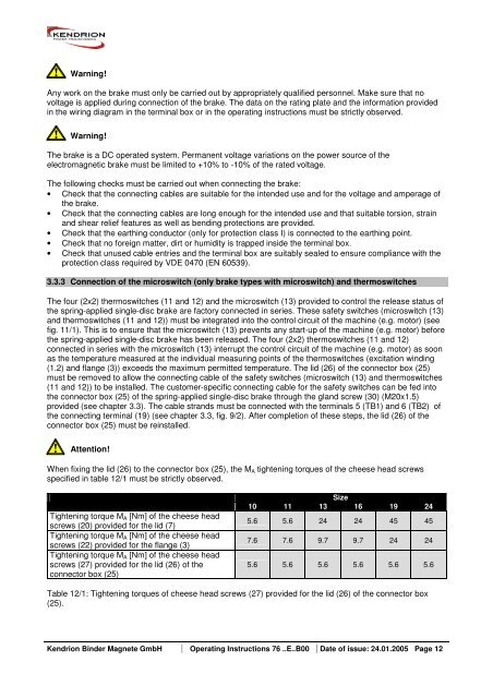
Warning!<br />
Any work on the brake must only be carried out by appropriately qualified personnel. Make sure that no<br />
voltage is applied during <strong>co</strong>nnection of the brake. The data on the rating plate and the information provided<br />
in the wiring diagram in the terminal box or in the operating instructions must be strictly observed.<br />
Warning!<br />
The brake is a DC operated system. Permanent voltage variations on the power source of the<br />
electromagnetic brake must be limited to +10% to -10% of the rated voltage.<br />
The following checks must be carried out when <strong>co</strong>nnecting the brake:<br />
• Check that the <strong>co</strong>nnecting cables are suitable for the intended use and for the voltage and amperage of<br />
the brake.<br />
• Check that the <strong>co</strong>nnecting cables are long enough for the intended use and that suitable torsion, strain<br />
and shear relief features as well as bending protections are provided.<br />
• Check that the earthing <strong>co</strong>nductor (only for protection class I) is <strong>co</strong>nnected to the earthing point.<br />
• Check that no foreign matter, dirt or humidity is trapped inside the terminal box.<br />
• Check that unused cable entries and the terminal box are suitably sealed to ensure <strong>co</strong>mpliance with the<br />
protection class required by VDE 0470 (EN 60539).<br />
3.3.3 Connection of the microswitch (only brake types with microswitch) and thermoswitches<br />
The four (2x2) thermoswitches (11 and 12) and the microswitch (13) provided to <strong>co</strong>ntrol the release status of<br />
the spring-applied single-disc brake are factory <strong>co</strong>nnected in series. These safety switches (microswitch (13)<br />
and thermoswitches (11 and 12)) must be integrated into the <strong>co</strong>ntrol circuit of the machine (e.g. motor) (see<br />
fig. 11/1). This is to ensure that the microswitch (13) prevents any start-up of the machine (e.g. motor) before<br />
the spring-applied single-disc brake has been released. The four (2x2) thermoswitches (11 and 12)<br />
<strong>co</strong>nnected in series with the microswitch (13) interrupt the <strong>co</strong>ntrol circuit of the machine (e.g. motor) as soon<br />
as the temperature measured at the individual measuring points of the thermoswitches (excitation winding<br />
(1.2) and flange (3)) exceeds the maximum permitted temperature. The lid (26) of the <strong>co</strong>nnector box (25)<br />
must be removed to allow the <strong>co</strong>nnecting cable of the safety switches (microswitch (13) and thermoswitches<br />
(11 and 12)) to be installed. The customer-specific <strong>co</strong>nnecting cable for the safety switches can be fed into<br />
the <strong>co</strong>nnector box (25) of the spring-applied single-disc brake through the gland screw (30) (M20x1.5)<br />
provided (see chapter 3.3). The cable strands must be <strong>co</strong>nnected with the terminals 5 (TB1) and 6 (TB2) of<br />
the <strong>co</strong>nnecting terminal (19) (see chapter 3.3, fig. 9/2). After <strong>co</strong>mpletion of these steps, the lid (26) of the<br />
<strong>co</strong>nnector box (25) must be reinstalled.<br />
Attention!<br />
When fixing the lid (26) to the <strong>co</strong>nnector box (25), the MA tightening torques of the cheese head screws<br />
specified in table 12/1 must be strictly observed.<br />
Tightening torque MA [Nm] of the cheese head<br />
screws (20) provided for the lid (7)<br />
Tightening torque MA [Nm] of the cheese head<br />
screws (22) provided for the flange (3)<br />
Tightening torque MA [Nm] of the cheese head<br />
screws (27) provided for the lid (26) of the<br />
<strong>co</strong>nnector box (25)<br />
Size<br />
10 11 13 16 19 24<br />
5.6 5.6 24 24 45 45<br />
7.6 7.6 9.7 9.7 24 24<br />
5.6 5.6 5.6 5.6 5.6 5.6<br />
Table 12/1: Tightening torques of cheese head screws (27) provided for the lid (26) of the <strong>co</strong>nnector box<br />
(25).<br />
<strong>Kendrion</strong> <strong>Binder</strong> <strong>Magnete</strong> <strong>GmbH</strong> Operating Instructions 76 ..E..B00 Date of issue: 24.01.2005 Page 12


