Kendrion Binder Magnete GmbH Power Transmission - binder.co.za
Kendrion Binder Magnete GmbH Power Transmission - binder.co.za
Kendrion Binder Magnete GmbH Power Transmission - binder.co.za

Create successful ePaper yourself
Turn your PDF publications into a flip-book with our unique Google optimized e-Paper software.
Warning!<br />
If a hand release lever (29) is fitted to the brake and the maximum air gap smax (see technical specifications)<br />
has been exceeded (especially in case of a reduced rated torque M2), the hand release lever (29) may limit<br />
the axial movement of the armature (2). This would cause the torque to be reduced down to zero. Whenever<br />
carrying out maintenance work, check the degree of wear of the friction disc (5) and the air gap s and<br />
replace the friction disc (5) well before the maximum air gap smax (see technical specifications) is reached.<br />
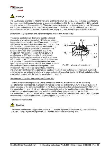
Microswitch (13) adjustment and replacement (only brakes with microswitch):<br />
The spring-applied single-disc brake must be released<br />
electrically to allow the microswitch (13) to be adjusted.<br />
Loosen the cheese head screws (20) provided on the lid (7)<br />
and remove the lid (7). Unscrew the locknut (13.1) and turn<br />
the set screw (13.2) clockwise until the microswitch (13)<br />
switches over (slightly audible click or <strong>co</strong>ntact closure<br />
between <strong>co</strong>ntacts 5 and 6 (see chapter 3.3). If the<br />
microswitch (13) is in ON position, it must be turned<br />
anticlockwise to OFF position. After the changeover<br />
position has been reached, <strong>co</strong>ntinue to turn the set screw<br />
(13.2) by 60° to 90°. Tighten the locknut (13.1). Make sure<br />
the set screw (13.2) position remains unchanged when<br />
tightening the locknut. Switch the brake on and off to check<br />
that the microswitch is in perfect working order. If the Fig. 20/1: Microswitch adjustment<br />
microswitch (13) needs to be replaced (e.g. when the<br />
maximum service life (switching operations) has been reached) (see technical specifications)), such work<br />
must be carried out by the manufacturer or by an authorized repair shop due to the difficult installation of the<br />
microswitch together with the four thermoswitches (11 and 12).<br />
Replacement of the four thermoswitches (11 and 12):<br />
The four thermoswitches (11 and 12) must be replaced when the maximum service life (switching<br />
operations) has been reached. Replacement must be carried out by the manufacturer or by an authorized<br />
repair shop due to the <strong>co</strong>mplex installation of the thermoswitches together with the microswitch (13) 1) . The<br />
thermoswitches (11 and 12) will only interrupt the <strong>co</strong>ntrol circuit of the machine (e.g. motor,) if the permitted<br />
maximum operating temperatures (see technical specifications) on the measuring points of the<br />
thermoswitches (11 and 12) are exceeded. Under normal <strong>co</strong>nditions, the thermoswitches (11 and 12) remain<br />
closed during the entire operation of the spring-applied single-disc brake.<br />
1) Brakes with microswitch<br />
Attention!<br />
The cheese head screws (20) provided on the lid (7) must be tightened to the torque MA specified in table<br />
12/1. The O-ring (24) and spring washer (21) must be installed as shown in fig. 6/1.<br />
<strong>Kendrion</strong> <strong>Binder</strong> <strong>Magnete</strong> <strong>GmbH</strong> Operating Instructions 76 ..E..B00 Date of issue: 24.01.2005 Page 20