Kendrion Binder Magnete GmbH Power Transmission - binder.co.za
Kendrion Binder Magnete GmbH Power Transmission - binder.co.za
Kendrion Binder Magnete GmbH Power Transmission - binder.co.za

Create successful ePaper yourself
Turn your PDF publications into a flip-book with our unique Google optimized e-Paper software.
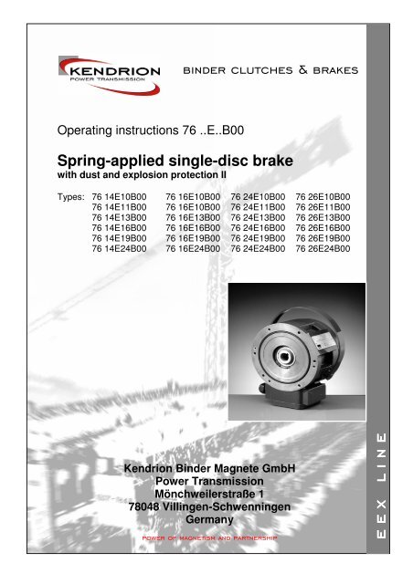
Operating instructions 76 ..E..B00<br />
Spring-applied single-disc brake<br />
with dust and explosion protection II<br />
Types: 76 14E10B00 76 16E10B00 76 24E10B00 76 26E10B00<br />
76 14E11B00 76 16E10B00 76 24E11B00 76 26E11B00<br />
76 14E13B00 76 16E13B00 76 24E13B00 76 26E13B00<br />
76 14E16B00 76 16E16B00 76 24E16B00 76 26E16B00<br />
76 14E19B00 76 16E19B00 76 24E19B00 76 26E19B00<br />
76 14E24B00 76 16E24B00 76 24E24B00 76 26E24B00<br />
<strong>Kendrion</strong> <strong>Binder</strong> <strong>Magnete</strong> <strong>GmbH</strong><br />
<strong>Power</strong> <strong>Transmission</strong><br />
Mönchweilerstraße 1<br />
78048 Villingen-Schwenningen<br />
Germany
Contents<br />
1. General ................................................................................................................................................... 3<br />
1.1 Preface .................................................................................................................................................3<br />
1.2 Standards and directives......................................................................................................................3<br />
1.3 EC Declaration of Conformity...............................................................................................................3<br />
1.4 EC Manufacturer's Declaration ............................................................................................................4<br />
1.5 Manufacturer's liability..........................................................................................................................4<br />
2. Product description............................................................................................................................... 5<br />
2.1 Operating principle ...............................................................................................................................5<br />
2.2 Brake design ........................................................................................................................................5<br />
3. Installation.............................................................................................................................................. 7<br />
3.1 Mechanical installation .........................................................................................................................7<br />
3.2 Installation of the hand release lever (only applicable to brake types with hand release lever)..........7<br />
3.3 Electrical <strong>co</strong>nnection and operation .....................................................................................................9<br />
3.3.1 DC power supply...........................................................................................................................9<br />
3.3.2 AC power supply.........................................................................................................................10<br />
3.3.3 Connection of the microswitch (only brake types with microswitch) and thermoswitches .........12<br />
3.4 Electromagnetic <strong>co</strong>mpatibility.............................................................................................................13<br />
3.5 Commissioning...................................................................................................................................16<br />
3.6 Adjustment of rated torque M2 ...........................................................................................................18<br />
4. Maintenance......................................................................................................................................... 18<br />
5. Delivery <strong>co</strong>ndition ............................................................................................................................... 21<br />
6. Emissions............................................................................................................................................. 21<br />
6.1 Noise ..................................................................................................................................................21<br />
6.2 Heat....................................................................................................................................................21<br />
7. Troubleshooting .................................................................................................................................. 22<br />
8. Safety instructions .............................................................................................................................. 23<br />
8.1 Intended use.......................................................................................................................................23<br />
8.2 General safety advice ........................................................................................................................23<br />
8.2.1 Project planning ..........................................................................................................................24<br />
8.2.2 Start-up .......................................................................................................................................24<br />
8.2.3 Installation...................................................................................................................................24<br />
8.2.4 Operation ....................................................................................................................................24<br />
8.2.5 Maintenance and repair ..............................................................................................................24<br />
8.3 Warning symbols................................................................................................................................25<br />
9. Definitions ............................................................................................................................................ 26<br />
10. Technical specifications..................................................................................................................... 28<br />
11. Product versions (types) .................................................................................................................... 30<br />
12. Authorized repair shops for maintenance and repair work ............................................................ 30<br />
Issued by: <strong>Kendrion</strong> <strong>Binder</strong> <strong>Magnete</strong> <strong>GmbH</strong><br />
<strong>Power</strong> <strong>Transmission</strong><br />
Replaces the issue dated: -<br />
Translation of original German operating instruction issue dated: 24.01.2005<br />
<strong>Kendrion</strong> <strong>Binder</strong> <strong>Magnete</strong> <strong>GmbH</strong> Operating Instructions 76 ..E..B00 Date of issue: 24.01.2005 Page 2
1. General<br />
1.1 Preface<br />
These operating instructions describe the operating principle and features of the 76 ..E..B00 series of<br />
<strong>Kendrion</strong> <strong>Binder</strong> spring-applied brakes. The safety instructions provided in this manual must be strictly<br />
observed during set-up of the machine (e.g. motor) and during start-up, operation and maintenance of the<br />
spring-applied brake. Should any questions arise with respect to torque, torque variations, installation<br />
position, wear, wear reserve, switching energy, running-in <strong>co</strong>nditions, release range, ambient <strong>co</strong>nditions etc.<br />
are to be <strong>co</strong>nsented with <strong>Kendrion</strong> <strong>Binder</strong> in advance. <strong>Kendrion</strong> <strong>Binder</strong> spring-applied brakes type<br />
76 ..E..B00 are products not ready for use. They are therefore referred to hereinafter as <strong>co</strong>mponents.<br />
1.2 Standards and directives<br />
The state-of-the-art <strong>co</strong>mponents are designed, built and tested in ac<strong>co</strong>rdance with the requirements of DIN<br />
VDE 0580 <strong>co</strong>ncerning electromagnetic equipment and <strong>co</strong>mponents. The <strong>co</strong>mponents are intended for use in<br />
potentially dusty and explosive atmospheres. The <strong>co</strong>mponents with protection class IP 56 are designed for<br />
use in potentially explosive atmospheres only and are approved to ATEX 100a (94/9/EC) requirements.<br />
Approvals: dust and explosion protection II Optional: explosion protection II<br />
II 2G EEx de II C T5 II 2G EEx de II C T5<br />
II 2D IP 67 T100°C IP 56<br />
DMT 02 ATEX E 122 DMT 02 ATEX E 122<br />
Being classified as "electromagnetic <strong>co</strong>mponents", spring-applied brakes are not subject to the Low Voltage<br />
Directive and must not bear a CE marking. Observance of the EMC Directive 89/336/EEC must be ensured<br />
by the user by suitable switchgear and/or drives. A CE marking in ac<strong>co</strong>rdance with ATEX 100a Directive<br />
(94/9/EC) is effected.<br />
1.3 EC Declaration of Conformity<br />
in ac<strong>co</strong>rdance with ATEX 100a Directive (94/9/EC)<br />
We herewith declare that the products specified below have been developed in ac<strong>co</strong>rdance with the ATEX<br />
Directive 94/9/EC and that they are built in <strong>co</strong>mpliance with the requirements of said directive.<br />
Certification authority: EXAM BBG Prüf- und Zertifizier <strong>GmbH</strong><br />
Dinnendahlstr. 9<br />
D-44809 Bochum<br />
EC design approval certificate: DMT 02 ATEX E 122<br />
Manufacturer: <strong>Kendrion</strong> <strong>Binder</strong> <strong>Magnete</strong> <strong>GmbH</strong><br />
<strong>Power</strong> <strong>Transmission</strong><br />
Mönchweilerstraße 1<br />
D-78048 Villingen-Schwenningen<br />
Applied standards and regulations:<br />
VDE 0470 (EN 60529) Enclosure protection ratings<br />
DIN VDE 0580 Electromagnetic devices and <strong>co</strong>mponents<br />
DIN EN 50014 Electrical products for potentially explosive atmospheres<br />
(general requirements)<br />
DIN EN 50018 Electrical products for potentially explosive atmospheres<br />
(flameproof enclosure "d")<br />
DIN EN 50019 Electrical products for potentially explosive atmospheres<br />
(increased safety "e")<br />
<strong>Kendrion</strong> <strong>Binder</strong> <strong>Magnete</strong> <strong>GmbH</strong> Operating Instructions 76 ..E..B00 Date of issue: 24.01.2005 Page 3
Products: Electromagnetically released spring-applied single-disc brake<br />
76 14E10B00 76 16EG10B00 76 24E10B00 76 26E10B00<br />
76 14E11B00 76 16E11B00 76 24E11B00 76 26E11B00<br />
76 14E13B00 76 16E13B00 76 24E13B00 76 26E13B00<br />
76 14E16B00 76 16E16B00 76 24E16B00 76 26E16B00<br />
76 14E19B00 76 16E19B00 76 24E19B00 76 26E19B00<br />
76 14E24B00 76 16E24B00 76 24E24B00 76 26E24B00<br />
<strong>Kendrion</strong> <strong>Binder</strong> <strong>Magnete</strong> <strong>GmbH</strong><br />
<strong>Power</strong> <strong>Transmission</strong> Villingen, 24.01.2005 ..........................................................<br />
Rudolf Schlosser<br />
(Business Manager)<br />
1.4 EC Manufacturer's Declaration<br />
in ac<strong>co</strong>rdance with Appendix II B of EC Machinery Directive (98/37/EC):<br />
We herewith declare that the products specified below are intended to be in<strong>co</strong>rporated in machines or<br />
assembled with other <strong>co</strong>mponents to form a machine. The machine must not be put into service until it has<br />
been declared in <strong>co</strong>nformity with the provisions of the Machinery Directive 98/37/EC.<br />
Manufacturer: <strong>Kendrion</strong> <strong>Binder</strong> <strong>Magnete</strong> <strong>GmbH</strong><br />
<strong>Power</strong> <strong>Transmission</strong><br />
Mönchweilerstraße 1<br />
D-78048 Villingen-Schwenningen<br />
Applied standards and regulations:<br />
VDE 0470 (EN 60529) Enclosure protection ratings<br />
DIN VDE 0580 Electromagnetic devices and <strong>co</strong>mponents<br />
DIN EN 50014 Electrical products for potentially explosive atmospheres<br />
(general requirements)<br />
DIN EN 50018 Electrical products for potentially explosive atmospheres<br />
(flameproof enclosure "d")<br />
DIN EN 50019 Electrical products for potentially explosive atmospheres<br />
(increased safety "e")<br />
Products: Electromagnetically released spring-applied single-disc brake<br />
76 14E10B00 76 16E10B00 76 24E10B00 76 26E10B00<br />
76 14E11B00 76 16E11B00 76 24E11B00 76 26E11B00<br />
76 14E13B00 76 16E13B00 76 24E13B00 76 26E13B00<br />
76 14E16B00 76 16E16B00 76 24E16B00 76 26E16B00<br />
76 14E19B00 76 16E19B00 76 24E19B00 76 26E19B00<br />
76 14E24B00 76 16E24B00 76 24E24B00 76 26E24B00<br />
<strong>Kendrion</strong> <strong>Binder</strong> <strong>Magnete</strong> <strong>GmbH</strong><br />
<strong>Power</strong> <strong>Transmission</strong> Villingen, 24.01.2005 ..........................................................<br />
Rudolf Schlosser<br />
(Business Manager)<br />
1.5 Manufacturer's liability<br />
The manufacturer will not assume any responsibility for damage caused by failure to use the products in<br />
ac<strong>co</strong>rdance with their intended use or by failure to observe the instructions provided in these operating<br />
instructions.<br />
The information <strong>co</strong>ntained in this manual has been updated before release of this issue. Such information<br />
shall not entitle users to raise claims with respect to <strong>co</strong>mponents purchased at an earlier date.<br />
<strong>Kendrion</strong> <strong>Binder</strong> <strong>Magnete</strong> <strong>GmbH</strong> Operating Instructions 76 ..E..B00 Date of issue: 24.01.2005 Page 4
2. Product description<br />
2.1 Operating principle<br />
The spring-applied single-disc brake is designed for dry operation. The dynamic effect of an electromagnetic<br />
field is utilized to over<strong>co</strong>me the braking effect produced by the spring force.<br />
The spring-applied single-disc brake engages in currentless <strong>co</strong>ndition and releases when AC voltage is<br />
applied. Owing to the form-fit <strong>co</strong>nnection between the friction disc and hub and due to the <strong>co</strong>nnection of the<br />
hub with the machine shaft (e.g. motor shaft), the torque generated by the spring-applied brake (brake<br />
torque) is transmitted to the machine (e.g. motor). Explosion-proof spring-applied single-disc brakes are<br />
characterized in that all <strong>co</strong>mponents that may ignite explosive mixtures are placed in an enclosure designed<br />
to withstand the specified test pressure in case the mixture explodes inside the enclosure and to prevent any<br />
mixtures outside the enclosure from being affected by the explosion.<br />
2.2 Brake design<br />
The magnet housing (1.1) of the spring-applied single-disc brake ac<strong>co</strong>mmodates the firmly fitted excitation<br />
winding (1.2) with pigtails which are <strong>co</strong>nnected with the <strong>co</strong>nnecting terminal (19) inside the <strong>co</strong>nnector box<br />
(25). The flange (3) and friction plate (33) are screwed to the magnet housing (1.1) by means of cheese<br />
head screws (22). The magnet housing (1.1) and the lid (7) are pressure sealed by means of cheese head<br />
screws (20). Owing to the spring force generated by the <strong>co</strong>mpression springs (4 and 35), the friction disc (5)<br />
is pressed over the armature (2) against the friction plate (33) and flange (3) to generate the braking effect of<br />
the spring-applied brake. The friction disc (5) and hub (17) <strong>co</strong>nstituting the rotating part of the spring-applied<br />
brake are <strong>co</strong>nnected with the shaft to be braked. The friction disc (5) features a square socket and can be<br />
moved on the hub (17) in axial direction. Spacer sleeves (6) are provided to allow the air gap 's' to be<br />
adjusted. The customer-specific <strong>co</strong>nnecting cable can be fed into the <strong>co</strong>nnector box (25) through a gland<br />
screw (30) (M20x1.5). When AC voltage is applied to the excitation winding (1.2) of the spring-applied singledisc<br />
brake, the spring force is <strong>co</strong>mpensated by the dynamic effect of the electromagnetic field. This causes<br />
the armature (2) to be released and the braking effect to be neutralized. The shaft to be braked is not<br />
subjected to any axial force by the brake. The spring-applied single-disc brake is equipped with a redundant<br />
thermoswitch system (2x2 thermoswitches) (11 and 12) and with a microswitch (13) 1) . The microswitch (13)<br />
is provided to prevent machine (e.g. motor) start-up before the brake has been released. The four (2x2)<br />
thermoswitches (11 and 12) <strong>co</strong>nnected in series with the microswitch (13) interrupt the <strong>co</strong>ntrol circuit of the<br />
machine (e.g. motor) as soon as the maximum permitted brake temperature is exceeded. When using<br />
brakes with hand release lever (29), openings must be provided in the part enclosing the brake (e.g. fan<br />
hood) to allow the lever to be installed. The hand release lever (29) 2) allows the brake to be released<br />
manually (e.g. in case of power failure).<br />
1) brake types with microswitch<br />
2) brake types with hand release lever<br />
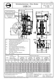
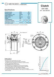
Key to figures:<br />
1.1 Magnet housing 13.3 Angle 25 Connector box<br />
1.2 Excitation winding 13.4 Countersunk screw 26 Lid<br />
2 Armature 13.5 Plate 27 Cheese head screw<br />
3 Flange 13.6 Cheese head screw 28 Spring washer<br />
4 Compression spring 13.7 Connecting cable (microswitch) 29 Hand release lever<br />
5 Friction disc 14 Circlip (outer ring) 29.1 Cam<br />
6 Spacer sleeve 15 Circlip (inner ring) 30 Gland screw<br />
7 Lid 16 O-ring 30.1 Cap nut<br />
8 Fixing surface 17 Hub 30.2 Connector sleeve<br />
9 Flat packing 18 Deep groove ball bearing 30.3 Sealing ring<br />
10 Fixing screw 19 Connecting terminal 31 Locknut<br />
11 Thermoswitch (2 pcs.) 20 Cheese head screw 32 Cheese head screw<br />
12 Thermoswitch (2 pcs.) 21 Spring washer 33 Friction plate<br />
13 Microswitch 22 Cheese head screw 34 Rating plate<br />
13.1 Locknut 23 Spring washer 35 Compression spring<br />
13.2 Set screw 24 O-ring<br />
<strong>Kendrion</strong> <strong>Binder</strong> <strong>Magnete</strong> <strong>GmbH</strong> Operating Instructions 76 ..E..B00 Date of issue: 24.01.2005 Page 5
<strong>Kendrion</strong> <strong>Binder</strong> <strong>Magnete</strong> <strong>GmbH</strong> Operating Instructions 76 ..E..B00 Date of issue: 24.01.2005 Page 6<br />
A i r g a p<br />
Fig. 6/1: Spring-applied single-disc brake 76 26E..B00
3. Installation<br />
3.1 Mechanical installation<br />
The spring-applied single-disc brake with its hub (17) must be slipped onto a<br />
shaft (tolerance h6) provided with a feather key in ac<strong>co</strong>rdance with DIN 6885,<br />
sheet 1. As the hub (17) is firmly fitted to the brake, it need not be axially<br />
secured on the shaft. Make sure that no radial forces act on the deep groove<br />
ball bearing (18) during installation and that the hub (17) is not exposed to any<br />
permanent axial force (e.g. exerted by shaft shoulder) after installation has<br />
been <strong>co</strong>mpleted. The spring-applied brake is centred by means of the deep<br />
groove ball bearing (18) of the hub (17). Fixing screws (10) are provided to<br />
allow the spring-applied single-disc brake to be screwed to the fixing surface<br />
(8) of the machine (e.g. motor). Before starting installation work, the O-ring<br />
(16) must be inserted in the <strong>co</strong>rresponding groove provided in the magnet<br />
housing (1.1). Make sure the fixing screws (10) are tightened uniformly and<br />
that the specified tightening torques (see table 7/1) are not exceeded.<br />
Attention!<br />
Make sure that the deep groove ball bearing (18) is not distorted during the installation of the spring-applied<br />
single-disc brake, and ensure the smooth running of the shaft when the brake is released. No sliding should<br />
be heard.<br />
Size<br />
10 11 13 16 19 24<br />
L [mm] 70 70 90 90 100 100<br />
MA [Nm] 9.7 9.7 24 24 45 45<br />
Table 7/1: Hub (17) dimensions; fixing screw (10) tightening torques<br />
Check that the fixing surface (8) meets the following requirements before installing the brake:<br />
• Axial <strong>co</strong>ncentricity relative to the shaft end in ac<strong>co</strong>rdance with DIN 42955-N<br />
(measuring radius = hole circle)<br />
• Material: steel, cast iron, aluminium – with excellent thermal <strong>co</strong>nductivity<br />
• Absence of oil and grease<br />
Radial runout of the shaft end relative to the fixing surface (8) in ac<strong>co</strong>rdance with DIN 42955-N<br />
Attention!<br />
The specified requirements in terms of the axial runout of the fixing surface (8) relative to the shaft end and<br />
in terms of the true running of the shaft end must be strictly observed in order not to affect the functioning<br />
and service life of the spring-applied single-disc brake. Before installing the brake, the shaft end must be<br />
slightly lubricated with highly temperature resistant grease (e.g. Copaslip). This is to ensure that the brake<br />
can be easily removed if, for example, maintenance work needs to be carried out.<br />
3.2 Installation of the hand release lever (only applicable to brake types with hand release lever)<br />
The lever of the hand release lever (29) must be inserted in the square socket of the two cams (29.1) which<br />
are firmly fitted to the circumference of the magnet housing (1.1). Make sure the lever is <strong>co</strong>rrectly positioned.<br />
The mechanic release forces F and the maximum release forces (operating force) Fmax are shown in table<br />
8.1.<br />
<strong>Kendrion</strong> <strong>Binder</strong> <strong>Magnete</strong> <strong>GmbH</strong> Operating Instructions 76 ..E..B00 Date of issue: 24.01.2005 Page 7
Caution!<br />
The brake torque can be neutralized manually by means of the hand release lever (29). Consequently, the<br />
brake must be installed in such a way that any unintentional actuation of the hand release lever (29) is<br />
excluded and that perfect operation of the spring-applied brake is ensured. The hand release lever (29) must<br />
not be used to release the brake during normal operation.<br />
<strong>Kendrion</strong> <strong>Binder</strong> <strong>Magnete</strong> <strong>GmbH</strong> Operating Instructions 76 ..E..B00 Date of issue: 24.01.2005 Page 8<br />
Size<br />
10 11 13 16 19 24<br />
Release force F [N] approx. 18 approx. 35 approx. 45 approx. 90 approx. 85 approx. 170<br />
Max. release force (operating force Fmax<br />
[N]<br />
50 50 125 125 240 240<br />
Tab 8/1: Release force und setting dimensions of hand release lever<br />
Warning:<br />
The mechanic hand release lever (29) must be in centre position when not actuated (see fig. 6.1), as only in<br />
this position a fully engaged brake can be ensured. If this is not achieved, it cannot be ensured that the full<br />
braking effect of the spring-applied single-disc brake is reached. In this case the user shall immediately stop<br />
the equipment and/or machine (e.g. motor). The brake can only be put into operation, if the proper<br />
functioning of the hand release lever (29) and the automatic return movement of the hand release lever in<br />
the centre position are ensured (see. fig. 6/1).
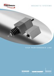
3.3 Electrical <strong>co</strong>nnection and operation<br />
The spring-applied single-disc<br />
brake must be <strong>co</strong>nnected to an AC<br />
power source by the terminals 1<br />
(BD1) and 2 (BD2) (see fig. 9/2).<br />
The customer-specific <strong>co</strong>nnecting<br />
cable must be <strong>co</strong>nnected to the<br />
terminals (19) by means of a gland<br />
screw (30) (M20x1.5). The lid (26)<br />
Fig. 9/1<br />
of the <strong>co</strong>nnector box (25) must be<br />
removed to allow the individual<br />
strands of the cable to be <strong>co</strong>nnected to the terminal (19). The<br />
<strong>co</strong>nnector sleeve (30.2) of the gland screw (30) is firmly screwed to<br />
the magnet housing (1.1) when delivered (see fig. 9/1, MA = 12<br />
Nm). The cap nut (30.1) must be tightened applying a tightening<br />
torque of MA = 12 Nm in order to seal, clamp and strain-relieve the<br />
customer-specific <strong>co</strong>nnecting cable. After <strong>co</strong>mpletion of these<br />
steps, the lid (26) of the <strong>co</strong>nnector box (25) must be closed.<br />
Attention!<br />
When fixing the lid (26) to the <strong>co</strong>nnector box (25), the MA tightening torques of the cheese head screws<br />
specified in table 12/1 must be strictly observed. The flat packing (9) and spring washer (28) must be<br />
installed as shown in fig. 6/1.<br />
The supply voltage is effected by means of the built-in bridge rectifier as well as the half-wave rectifier or a<br />
<strong>co</strong>mbination of both. Various types of rectifiers (see tab. 10/1 excerpt) are available for direct <strong>co</strong>nnection to<br />
an AC network. Voltage ripple due to intermittent power supply may cause the brake to hum or not work<br />
<strong>co</strong>rrectly depending on size and torques. Perfect operation of the brake must be ensured by the user or<br />
system manufacturer by providing suitable electrical <strong>co</strong>ntrol.<br />
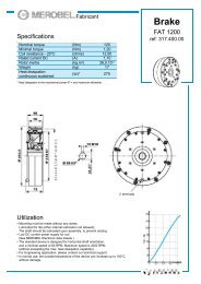
3.3.1 DC power supply<br />
The general <strong>co</strong>urse of the voltage when switching off the<br />
excitation winding (<strong>co</strong>il) (1.2) <strong>co</strong>rresponds to the opposite<br />
graph.<br />
Attention!<br />
The spike Uvmax during switch-off may reach several 1000 v in<br />
the millise<strong>co</strong>nd range, if no protective system is installed. The<br />
excitation winding (<strong>co</strong>il) (1.2), switching <strong>co</strong>ntacts and electronic<br />
<strong>co</strong>mponents may be damaged. When switching-off, sparking<br />
may occur at the switch. When switching-off, the current is<br />
therefore to be reduced by a protective wiring, leading also to a<br />
reduction of the voltage. The protective wiring is integrated in<br />
<strong>Kendrion</strong> <strong>Binder</strong> rectifiers (see tab. 10/1) and is sufficient for<br />
standard applications.<br />
Attention!<br />
Sensitive electronic <strong>co</strong>mponents (e.g. logical <strong>co</strong>mponents) may<br />
also be damaged by lower voltage.<br />
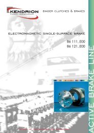
Connecting terminal<br />
<strong>co</strong>ntact assignment<br />
<strong>Kendrion</strong> <strong>Binder</strong> <strong>Magnete</strong> <strong>GmbH</strong> Operating Instructions 76 ..E..B00 Date of issue: 24.01.2005 Page 9<br />
Thermo<br />
switch (11)<br />
Thermo<br />
switch (12)<br />
B r i d g e<br />
r e c t i f i e r<br />
Fig. 9/2<br />
M<br />
0,9 x M 2<br />
U<br />
U B<br />
Microswitch (13)<br />
B r a k e<br />
t<br />
11<br />
t<br />
1<br />
S a f e t y<br />
s w i t c h e s<br />
M1<br />
t<br />
t<br />
U Vmax<br />
UB Operating voltage (<strong>co</strong>il voltage)<br />
UVmax Cutoff voltage<br />
J u m p e r
3.3.2 AC power supply<br />
Direct <strong>co</strong>nnection of the spring-applied single-disc brake to an AC power source is only possible by a<br />
rectifier. Wiring of the brake in case of single-phase AC voltage supply must be performed similar to threephase<br />
voltage. The <strong>co</strong>upling times vary depending on the switching type (DC side switching or AC side<br />
switching).<br />
Half-wave rectification:<br />
In case of half-wave rectification, a <strong>co</strong>il voltage U2 occurs which is lower than the rectifier input voltage (by<br />
factor 0,445). Compared with bridge rectification, half-wave rectifiers have a high residual ripple causing<br />
slightly shorter switching times depending on the size of the brake. The half-wave rectifier is therefore<br />
preferred (also due to its lower <strong>co</strong>il voltage).<br />
In case of smaller sizes, humming of the brake may occur.<br />
Bridge rectification:<br />
Bridge rectifiers provide voltage with minimum residual ripple avoiding brake humming, even if small-size<br />
brakes are used. In case of bridge rectification, the U2 <strong>co</strong>il voltage is lower than the rectifier input voltage (by<br />
factor 0.89).<br />
AC side switching:<br />
In case of AC side switching, the switching <strong>co</strong>ntact for the spring-applied single-disc brake is provided on the<br />
AC voltage side directly before the rectifier. It must be <strong>co</strong>nsidered, however, that the bridge rectifier with its<br />
free-wheel diode may extend the <strong>co</strong>upling time significantly (by factor 5 or more) after AC voltage has been<br />
removed. The dis<strong>co</strong>nnection times remain unchanged.<br />
DC side switching:<br />
In case of DC side brake switching, an auxiliary <strong>co</strong>ntact is provided on the brake <strong>co</strong>ntactor, for example. This<br />
auxiliary <strong>co</strong>ntact is designed to interrupt the power supply on the DC side.<br />
Attention:<br />
In case of DC side switching, the brake must be operated with an protective wiring to avoid excessive<br />
voltage. The switching times indicated in the Technical Data refer to DC side switching of the brake.<br />
Re<strong>co</strong>mmended rectifiers:<br />
Designation Type of rectifier<br />
Nominal input voltage<br />
range<br />
U1/VAC (40-60Hz)<br />
Output voltage<br />
U2/VDC<br />
Max. output current<br />
R load<br />
I/ADC<br />
32 07.22A.0 Half-wave 0-500 (±10%) U1 • 0,445 1,6 2,0<br />
32 07.23A.0 Bridge 0-400 (±10%) U1 • 0,890 1,6 2,0<br />
32 17350E..<br />
32 17.2.A..<br />
Tab. 10/1<br />
Overexcitation<br />
Bridge Halfwave<br />
Overexcitation<br />
Bridge Halfwave<br />
L load<br />
I/ADC<br />
48-525 (±10%) U1 • 0,890 / U1 • 0,445 2,3 3<br />
110-230 (±10%)<br />
220-415 (±10%)<br />
U1 • 0,890 / U1 • 0,445<br />
Please see data sheets of the respective rectifier types<br />
<strong>Kendrion</strong> <strong>Binder</strong> <strong>Magnete</strong> <strong>GmbH</strong> Operating Instructions 76 ..E..B00 Date of issue: 24.01.2005 Page 10<br />
1,2<br />
0,8<br />
1,5<br />
1,0
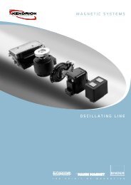
1<br />
3<br />
5<br />
N<br />
N<br />
5<br />
5<br />
M<br />
3~<br />
L1 L2 L3<br />
M<br />
3~<br />
L1 L2 L3<br />
Fig. 11/1: Proposal: wiring of brake with safety switch (wiring diagram)<br />
4<br />
4<br />
AC side switching<br />
DC side switching<br />
- ~ ~ +<br />
- ~ ~ +<br />
Half-wave rectifier and/or bridge rectifier 2 Brake excitation winding (<strong>co</strong>il)<br />
Control relay for brake 4 Safety switches (<strong>co</strong>ntacts for<br />
microswitch (only brake types with<br />
microswitch) and thermoswitches)<br />
Control relay for machine (e.g. motor) 6. Half-wave and/or bridge rectifier with<br />
DC side cutoff<br />
<strong>Kendrion</strong> <strong>Binder</strong> <strong>Magnete</strong> <strong>GmbH</strong> Operating Instructions 76 ..E..B00 Date of issue: 24.01.2005 Page 11<br />
3<br />
3<br />
2<br />
2<br />
1<br />
1
Warning!<br />
Any work on the brake must only be carried out by appropriately qualified personnel. Make sure that no<br />
voltage is applied during <strong>co</strong>nnection of the brake. The data on the rating plate and the information provided<br />
in the wiring diagram in the terminal box or in the operating instructions must be strictly observed.<br />
Warning!<br />
The brake is a DC operated system. Permanent voltage variations on the power source of the<br />
electromagnetic brake must be limited to +10% to -10% of the rated voltage.<br />
The following checks must be carried out when <strong>co</strong>nnecting the brake:<br />
• Check that the <strong>co</strong>nnecting cables are suitable for the intended use and for the voltage and amperage of<br />
the brake.<br />
• Check that the <strong>co</strong>nnecting cables are long enough for the intended use and that suitable torsion, strain<br />
and shear relief features as well as bending protections are provided.<br />
• Check that the earthing <strong>co</strong>nductor (only for protection class I) is <strong>co</strong>nnected to the earthing point.<br />
• Check that no foreign matter, dirt or humidity is trapped inside the terminal box.<br />
• Check that unused cable entries and the terminal box are suitably sealed to ensure <strong>co</strong>mpliance with the<br />
protection class required by VDE 0470 (EN 60539).<br />
3.3.3 Connection of the microswitch (only brake types with microswitch) and thermoswitches<br />
The four (2x2) thermoswitches (11 and 12) and the microswitch (13) provided to <strong>co</strong>ntrol the release status of<br />
the spring-applied single-disc brake are factory <strong>co</strong>nnected in series. These safety switches (microswitch (13)<br />
and thermoswitches (11 and 12)) must be integrated into the <strong>co</strong>ntrol circuit of the machine (e.g. motor) (see<br />
fig. 11/1). This is to ensure that the microswitch (13) prevents any start-up of the machine (e.g. motor) before<br />
the spring-applied single-disc brake has been released. The four (2x2) thermoswitches (11 and 12)<br />
<strong>co</strong>nnected in series with the microswitch (13) interrupt the <strong>co</strong>ntrol circuit of the machine (e.g. motor) as soon<br />
as the temperature measured at the individual measuring points of the thermoswitches (excitation winding<br />
(1.2) and flange (3)) exceeds the maximum permitted temperature. The lid (26) of the <strong>co</strong>nnector box (25)<br />
must be removed to allow the <strong>co</strong>nnecting cable of the safety switches (microswitch (13) and thermoswitches<br />
(11 and 12)) to be installed. The customer-specific <strong>co</strong>nnecting cable for the safety switches can be fed into<br />
the <strong>co</strong>nnector box (25) of the spring-applied single-disc brake through the gland screw (30) (M20x1.5)<br />
provided (see chapter 3.3). The cable strands must be <strong>co</strong>nnected with the terminals 5 (TB1) and 6 (TB2) of<br />
the <strong>co</strong>nnecting terminal (19) (see chapter 3.3, fig. 9/2). After <strong>co</strong>mpletion of these steps, the lid (26) of the<br />
<strong>co</strong>nnector box (25) must be reinstalled.<br />
Attention!<br />
When fixing the lid (26) to the <strong>co</strong>nnector box (25), the MA tightening torques of the cheese head screws<br />
specified in table 12/1 must be strictly observed.<br />
Tightening torque MA [Nm] of the cheese head<br />
screws (20) provided for the lid (7)<br />
Tightening torque MA [Nm] of the cheese head<br />
screws (22) provided for the flange (3)<br />
Tightening torque MA [Nm] of the cheese head<br />
screws (27) provided for the lid (26) of the<br />
<strong>co</strong>nnector box (25)<br />
Size<br />
10 11 13 16 19 24<br />
5.6 5.6 24 24 45 45<br />
7.6 7.6 9.7 9.7 24 24<br />
5.6 5.6 5.6 5.6 5.6 5.6<br />
Table 12/1: Tightening torques of cheese head screws (27) provided for the lid (26) of the <strong>co</strong>nnector box<br />
(25).<br />
<strong>Kendrion</strong> <strong>Binder</strong> <strong>Magnete</strong> <strong>GmbH</strong> Operating Instructions 76 ..E..B00 Date of issue: 24.01.2005 Page 12
3.4 Electromagnetic <strong>co</strong>mpatibility<br />
As required by the German Electromagnetic Compatibility Act (EMVG), electromagnetic <strong>co</strong>mpatibility must<br />
be guaranteed to ensure immunity to external electromagnetic fields and <strong>co</strong>nducted disturbances.<br />
Furthermore, the emission of electromagnetic fields and <strong>co</strong>nducted disturbances during brake operation<br />
must be minimized. Since the brake features depend on the circuitry and operation, a declaration of<br />
<strong>co</strong>nformity with the applicable EMC standard can only be furnished for the wiring type, but not for the<br />
individual <strong>co</strong>mponents.<br />
The spring-applied single-disc brakes type 76 ..E..B00 are designed for industrial applications to which the<br />
following EMC standards apply: Generic Immunity Standard VKE 0839, part 6-2 (EN 61000-6-2), and<br />
Generic Emission Standard VDE 0839, part 81-2 (EN 50081-2).<br />
Other applications may be subject to different generic standards which must be <strong>co</strong>nsidered by the<br />
manufacturer of the overall system.<br />
The requirements in terms of electromagnetic <strong>co</strong>mpatibility of devices and <strong>co</strong>mponents are determined by<br />
basic standards derived from the generic standards.<br />
Brake wiring re<strong>co</strong>mmendations are therefore provided in the following to ensure <strong>co</strong>mpliance with the<br />
individual basic standards that are relevant for industrial use of the brake and some other applications.<br />
Additional information on electromagnetic <strong>co</strong>mpatibility – in particular of the electronic rectifiers under 3.3. –<br />
is given in the respective data sheets.<br />
Immunity ac<strong>co</strong>rding to EN 61000-4:<br />
EN 61000-4-2 Electrostatic discharge:<br />
The spring-applied single-disc brakes type 76 ..E..B00 <strong>co</strong>mply at least with severity level 3 without requiring<br />
any further measures. The rectifiers re<strong>co</strong>mmended under 3.3 <strong>co</strong>nform to severity level 3 without requiring<br />
any further measures.<br />
EN 61000-4-3 Electromagnetic fields:<br />
The brakes <strong>co</strong>mply at least with severity level 3 without requiring any further measures. The rectifiers<br />
re<strong>co</strong>mmended under 3.3 <strong>co</strong>nform to severity level 3 without requiring any further measures.<br />
EN 61000-4-4 Fast transients (burst):<br />
The brakes <strong>co</strong>mply at least with severity level 3 without requiring any further measures. The re<strong>co</strong>mmended<br />
rectifiers <strong>co</strong>nform to severity level 3. In case of products of 32 17.2.A.. series, a slight increase of voltage<br />
may occur for a certain time in case of severity level 3. But this increase has no influence on the functioning.<br />
EN 61000-4-5 Surge:<br />
The brakes <strong>co</strong>mply at least with severity level 3 without requiring any further measures. The re<strong>co</strong>mmended<br />
rectifiers <strong>co</strong>nform to severity level 3<br />
EN 61000-4-9 Pulse magnetic fields, EN 61000-4-10 Damped oscillatory magnetic fields:<br />
Since the operating magnetic fields of the electromagnetic <strong>co</strong>mponents are much stronger than interference<br />
fields, the brake function will remain unaffected. The brakes <strong>co</strong>mply at least with severity level 4. The<br />
re<strong>co</strong>mmended rectifiers <strong>co</strong>nform at least to severity level 3.<br />
EN 61000-4-11 Voltage dips, short interruptions, and short supply voltage variations:<br />
a) Voltage interruptions:<br />
Brakes that <strong>co</strong>mply with the requirements of DIN VDE 0580 are de-energized after the specified<br />
switching times at the latest. The switching time depends on the <strong>co</strong>ntrol and mains <strong>co</strong>nditions (e.g.<br />
generator effect of running down motors). Voltage interruptions of shorter duration than the response<br />
delay specified by DIN VDE 0580 will not cause any malfunctions. The user must ensure that any<br />
<strong>co</strong>nsequential damage is avoided (e.g. motor start-up before the brake has been released caused by a<br />
phase failure in case of two-phase energized motors or by the slipping of an electromagnetically<br />
engaged system due to torque drop). The functional reliability of the electromagnetic brake and its<br />
electronic accessories remains unaffected provided that the aforementioned <strong>co</strong>nsequential damage is<br />
avoided.<br />
<strong>Kendrion</strong> <strong>Binder</strong> <strong>Magnete</strong> <strong>GmbH</strong> Operating Instructions 76 ..E..B00 Date of issue: 24.01.2005 Page 13
) Voltage dips and short supply voltage fluctuations:<br />
Electromagnetically released systems:<br />
Voltage dips and supply voltage fluctuations to below 60% of the rated voltage and lasting longer than<br />
the response delay specified by DIN VDE 0580 may cause the brake to be de-energized temporarily.<br />
Consequential damage as described under a) above must be avoided by the user by taking adequate<br />
precautions.<br />
Electromagnetically engaged systems:<br />
Voltage dips and supply voltage fluctuations to below the minimum tolerance threshold will cause torque<br />
reductions. The user is required to take adequate precautions to avoid <strong>co</strong>nsequential damage.<br />
Radio interference suppression in ac<strong>co</strong>rdance with EN 55011:<br />
The brakes and the re<strong>co</strong>mmended electronic rectifiers are classified as Group 1 equipment in ac<strong>co</strong>rdance<br />
with EN 55011. As far as the emissions from this equipment are <strong>co</strong>ncerned, one distinguishes between field<br />
guided radiated interference and line-<strong>co</strong>nducted interference.<br />
a) Radiated interference:<br />
When operated with DC voltage or rectified 50/60 Hz AC voltage, all brakes <strong>co</strong>mply with the limit values<br />
applicable to Class B equipment.<br />
b) Interference voltage:<br />
When operated with DC, the electromagnetic<br />
<strong>co</strong>mponents <strong>co</strong>mply at least with the limit values of class<br />
A. When <strong>co</strong>nnected to a 50/60 Hz AC power source with<br />
electronic rectifiers or other electronic drives,<br />
interference suppression measures as shown in fig. 14/1<br />
must be taken to ensure <strong>co</strong>mpliance with the limit values<br />
R<br />
L<br />
applicable to Class A equipment. Interference<br />
suppression capacitors should be used which must be<br />
dimensioned to suit the <strong>co</strong>nnection data of the<br />
electromagnetic <strong>co</strong>mponents and the specific mains<br />
U<br />
<strong>co</strong>nditions. The re<strong>co</strong>mmended rectifiers listed under 3.3<br />
with CE marking ac<strong>co</strong>rding to EMVRL are already fitted<br />
with integrated interference suppression <strong>co</strong>mponents,<br />
unless otherwise indicated in the respective data sheet,<br />
class A ac<strong>co</strong>rding to EN 55011 is ensured at least.<br />
C<br />
When brakes are used with the re<strong>co</strong>mmended or other rectifiers, the re<strong>co</strong>mmended values specified in<br />
table 15/1 should be observed. Interference suppression <strong>co</strong>mponents should be installed as close as<br />
possible to the <strong>co</strong>nsumer. Interference caused during switching operations of the electromagnetic<br />
<strong>co</strong>mponent are generally attributable to the inductive load. Where necessary, assemblies designed to<br />
limit the cutoff voltage (e.g. anti-parallel diode) or voltage limiting <strong>co</strong>mponents (e.g. varistors, transil<br />
diodes, resistance/diode <strong>co</strong>mbinations and the like) can be installed. However, such <strong>co</strong>mponents will<br />
inevitably change the switching times of the brake. The rectifiers listed under 3.3 include diodes or<br />
varistors for voltage limiting. In case of DC side switching, a varistor suitable for the respective<br />
maximum operating voltage and parallel to the excitation winding (1.2) limits the spike to the<br />
re<strong>co</strong>mmended values indicated in tab. 15/2.<br />
If the user operates the <strong>co</strong>mponents together with other electronic accessories, <strong>co</strong>mpliance with EMC is to<br />
be ensured. Compliance with the applicable standards <strong>co</strong>ncerning the design and operation of <strong>co</strong>mponents,<br />
sub-assemblies or equipment employed shall not relieve the user and manufacturer of the overall system or<br />
equipment from their obligation to furnish proof of <strong>co</strong>nformity with such standards for the overall system or<br />
equipment.<br />
<strong>Kendrion</strong> <strong>Binder</strong> <strong>Magnete</strong> <strong>GmbH</strong> Operating Instructions 76 ..E..B00 Date of issue: 24.01.2005 Page 14
Type of rectifier<br />
Half-wave rectifier<br />
32 07.22A.0<br />
Bridge rectifier<br />
32 07.23A.0<br />
Overexcitation rectifier<br />
32 17350E..<br />
Overexcitation rectifier<br />
32 17.2.A..<br />
Table 15/1<br />
Nominal input voltage<br />
U1/VAC (40-60Hz)<br />
DC at L-load<br />
(ADC)<br />
up to 500 (+10%) up to 2.0<br />
up 400 (+10%) up to 2.0<br />
48-525 up to 3<br />
110-230<br />
220-415<br />
up to 1,5<br />
up to 1,0<br />
Rectifier input voltage / VAC Re<strong>co</strong>mmended cutoff voltage in case of DC<br />
side switching / V<br />
250 700<br />
Table 15/2<br />
440 1200<br />
550 1500<br />
630 1700<br />
Capacitor<br />
(nF(VAC)<br />
No additional<br />
interference<br />
suppression<br />
measures required<br />
No additional<br />
interference<br />
suppression<br />
measures required<br />
No additional<br />
interference<br />
suppression<br />
measures required<br />
No additional<br />
interference<br />
suppression<br />
measures required<br />
<strong>Kendrion</strong> <strong>Binder</strong> <strong>Magnete</strong> <strong>GmbH</strong> Operating Instructions 76 ..E..B00 Date of issue: 24.01.2005 Page 15
3.5 Commissioning<br />
Warning!<br />
The operational check of the brake may only be performed after the machine (e.g. motor) has been switched<br />
off and secured against accidental or unintentional start-up.<br />
The following checks must be carried out:<br />
Check <strong>co</strong>mpliance with the information provided on the rating plate with respect to design and protection<br />
class. Provided that the fixing surface (mounting side) (8) for the spring-applied single-disc brake is closed,<br />
no further measures need to be taken to ensure <strong>co</strong>mpliance with the required protection class. If the fixing<br />
surface (mounting side) (8) is open, adequate sealing must be provided in ac<strong>co</strong>rdance with the <strong>Kendrion</strong><br />
<strong>Binder</strong> re<strong>co</strong>mmended installation procedure E76 00A0030 000. In this case, the maximum possible<br />
protection rating is IP 56. After <strong>co</strong>nnection of the brake, an operational test must be performed to check that<br />
the friction disc (5) runs smoothly. For this purpose, turn the shaft (while the brake is energized and the<br />
machine (e.g. motor) is currentless).<br />
Rating plate information (example):<br />
Voltage frequency<br />
A p p r o v a l<br />
I d e n t i f i c a t i o n<br />
Max. switching power<br />
Reference number<br />
(quantity per order)<br />
Rated torque<br />
Brake type<br />
Rated current<br />
Rated voltage<br />
Index (layout<br />
drawing)<br />
ε<br />
Production date and<br />
IT number<br />
inspector's initials<br />
CE marking number<br />
Certification symbols:<br />
(in ac<strong>co</strong>rdance with EN 50014)<br />
II 2G Group II equipment; Category<br />
2G (for use in potentially<br />
explosive atmospheres of<br />
gases/vapours and mists);<br />
zones 1 and 2<br />
II 2D Group II equipment; Category<br />
2D (for use in potentially<br />
explosive atmospheres caused<br />
by <strong>co</strong>mbustible dusts); zones 21<br />
and 22<br />
IP67 T100°C IP 67 protection; max. surface<br />
temperature 100°C<br />
EEx de II C T5 Flameproof enclosure;<br />
increased safety;<br />
Group II equipment (electrical<br />
equipment for use in potentially<br />
explosive atmospheres except<br />
for underground workings);<br />
classification C (gas and vapour<br />
atmospheres);<br />
temperature class T5<br />
DMT 02 Certification authority and<br />
certification year<br />
ATEX E 122 Approval no.<br />
Zone 1: occasionally ha<strong>za</strong>rdous explosive atmosphere<br />
Zone 2: rarely and short-term ha<strong>za</strong>rdous explosive atmosphere<br />
Zone 21: occasionally ha<strong>za</strong>rdous explosive atmosphere during normal operation due to <strong>co</strong>mbustible dust<br />
Zone 22: short-term ha<strong>za</strong>rdous explosive atmosphere due to <strong>co</strong>mbustible dust; no ha<strong>za</strong>rd during normal<br />
operation<br />
After <strong>co</strong>mpletion of mounting, <strong>co</strong>vers and guards must be installed, where necessary.<br />
<strong>Kendrion</strong> <strong>Binder</strong> <strong>Magnete</strong> <strong>GmbH</strong> Operating Instructions 76 ..E..B00 Date of issue: 24.01.2005 Page 16
Caution!<br />
Before starting the machine (e.g. motor) test run without drive elements, the feather key (if used) must be<br />
secured so that it cannot be hurled out.<br />
Caution!<br />
The surface temperature of the brake may reach up to 100°C. Heat-sensitive parts such as standard cables<br />
or electronic <strong>co</strong>mponents must not be fixed to or be in <strong>co</strong>ntact with these surfaces. If necessary, suitable<br />
protections and hand guards must be installed to avoid accidental <strong>co</strong>ntact with hot surfaces! If the shaft<br />
needs to be turned during set-up operations while the machine (e.g. motor) is switched off, the brake must<br />
be released electromagnetically or by means of the hand release lever (29).<br />
Warning!<br />
The shaft must not be exposed to load torques. Before restarting the machine (e.g. motor), the brake must<br />
be de-energized.<br />
Attention!<br />
High-voltage tests performed during the installation of the brake in an overall system or during<br />
<strong>co</strong>mmissioning must be carried out in such a way that damage to the integrated electronic accessories is<br />
avoided. The limits for high-voltage tests and follow-up tests specified by DIN VDE 0580 must be observed.<br />
Attention!<br />
Check that the brake has been <strong>co</strong>nnected in ac<strong>co</strong>rdance with the specifications provided on the rating plate<br />
before it is <strong>co</strong>mmissioned. Even short-term operation outside the specified supply voltage limits may cause<br />
irreversible damage to the brake or electronic accessories. Such damage may not be apparent immediately.<br />
Attention!<br />
In particular DC side switching of the brake without protective elements as described under 3.4 causes shortterm<br />
damage of electronic rectifiers which are not suitable or electronic accessories, of the switching<br />
elements themselves and the excitation winding (1.2).<br />
<strong>Kendrion</strong> <strong>Binder</strong> <strong>Magnete</strong> <strong>GmbH</strong> Operating Instructions 76 ..E..B00 Date of issue: 24.01.2005 Page 17
3.6 Adjustment of rated torque M2<br />
The brakes are set to the rated torque M2 (as specified in the<br />
purchase order) before shipment. The factory-set rated torque M2 is<br />
indicated on the rating plate (33) of the brake. In case fine adjustment<br />
is required, the rated torque M2 can be <strong>co</strong>ntinuously reduced.<br />
However, it must not be increased. In order to adjust the torque,<br />
proceed as follows: Loosen the cheese head screws (20) provided on<br />
the lid (7) and remove the lid (7). Screw in the cheese head screw<br />
(32) clockwise by means of a screwdriver. The nut (31) must be<br />
secured in such a way that it cannot turn. Fine adjustment must be<br />
carried out uniformly on all cheese head screws (32). Make sure that the requirements in terms of the<br />
minimum length of projection xmin (see table 14/1) of the cheese head screw (32) from the flange (3) are not<br />
fallen short of. The change in the rated torque M2 resulting from these adjustments is specified in table 18/1.<br />
The factory-set nominal value (re<strong>co</strong>mmended value) of the length of projection xnom (see table 18/1) is<br />
marked on the flange.<br />
Size<br />
10 11 13 16 19 24<br />
∆M2/mm [Nm] 0.5 0.65 4 7.5 7.5 10<br />
xnom [mm] 10.5 10.5 11.5 11 11 11<br />
xmin [mm] 7.5 7.5 9 9 9 9<br />
Table 18/1: Change of rated torque M2 with 1 mm axial travel of the cheese head screw (32); permitted<br />
projection xmin<br />
Warning!<br />
The rated torque may only be adjusted by the manufacturer or by authorized and appropriately trained<br />
personnel.<br />
4. Maintenance<br />
The spring-applied single-disc brake does not require any particular maintenance except that the friction disc<br />
(5) must be replaced when worn (see technical specification for information on the max. air gap smax) and<br />
that the safety switches (microswitch (13) 1) and thermoswitches (11 and 12)) must be checked. These<br />
maintenance measures must be performed during the general inspection of the electrical equipment (e.g.<br />
motor). Make sure that the spring-applied brake is dis<strong>co</strong>nnected and that the explosion protection is not<br />
interfered with when carrying out maintenance work. When opening the flameproof enclosed magnet<br />
housing (1.1) to allow the friction disc (5) to be replaced, the safety information provided in this manual must<br />
be strictly observed. Always check that the gaps required to ensure protection against flame propagation are<br />
in perfect <strong>co</strong>ndition. Only use original spare parts of the spring-applied brake provided by the manufacturer.<br />
1) Brakes with microswitch<br />
Warning!<br />
Should the explosion protection features of the spring-applied brake be damaged during maintenance or<br />
repair work, the brake must be checked by an authorized expert before restarting it. Any measures required<br />
to restore explosion protection must be performed by the manufacturer or by authorized repair shops (see<br />
chapter 12).<br />
Removing the brake from the machine (e.g. motor):<br />
Loosen the cheese head screws (27) provided on the lid (26) of the <strong>co</strong>nnector box (25) and remove the lid<br />
(26). Dis<strong>co</strong>nnect the strands of the <strong>co</strong>nnecting cables (excitation winding (1.2) and safety switches) from the<br />
<strong>co</strong>nnecting terminal (19). Unscrew the cap nut (30.1) of the gland screw (30) and remove the <strong>co</strong>nnecting<br />
cables from the <strong>co</strong>nnector box (25). Loosen the fixing screws (10). Remove the brake from the shaft with the<br />
two pull-off threads provided on the magnet housing (1.1) and by means of cheese head screws (e.g. in<br />
ac<strong>co</strong>rdance with ISO 4762).<br />
<strong>Kendrion</strong> <strong>Binder</strong> <strong>Magnete</strong> <strong>GmbH</strong> Operating Instructions 76 ..E..B00 Date of issue: 24.01.2005 Page 18
Checking the air gap s:<br />
Loosen the cheese head screws (20) provided on the lid (7) and remove the lid (7). Place a measuring<br />
bridge with dial gauge on the flange (3) to measure the air gap s. Position the measuring tip of the<br />
micrometer screw on the friction disc (5).<br />
Release the spring-applied brake so that the air gap s can be determined from the difference between the<br />
values indicated by the dial gauge.<br />
Attention!<br />
Temporary electric release of the spring-applied brake is required to allow the air gap s to be measured. For<br />
information on the electrical <strong>co</strong>nnection of the brake to the power source, please refer to chapter 3.3.<br />
Replacing the friction disc (5):<br />
Remove the self-locking nut (31) from the cheese head screws (32). Loosen the cheese head screws (22)<br />
provided on the flange (3) and remove the flange (3). Remove the friction disc (5) from the hub (17) and<br />
replace it by a new one.<br />
Attention!<br />
Make sure that the <strong>co</strong>nnections of the four thermoswitches (11 and 12) are not damaged or loosened when<br />
removing the flange (3).<br />
Deep groove ball bearing (18):<br />
When performing maintenance and repair work, check that the deep groove ball bearing (18) rotates<br />
smoothly. In case the bearing (18) needs to be replaced, proceed as described under "Removing the brake<br />
from the machine (e.g. motor)" and "Opening the magnet housing (1.1)". After having removed the friction<br />
disc (5), remove the circlips (14 and 15). Push the hub (17) and deep groove ball bearing (18) out of the<br />
magnet housing (1.1) and remove the bearing (18) from the hub (17). Before reassembling the springapplied<br />
brake, all <strong>co</strong>mponents (except for the friction disc (5)) must be cleaned with grease-free cleaners. In<br />
order to assemble the individual <strong>co</strong>mponents, proceed in reverse order of removal. When fine adjusting the<br />
rated torque M2, make sure that the cheese head screws (32) project from the flange by the length xnom<br />
(re<strong>co</strong>mmended value – see table 18/1) marked on the flange (3). The self-locking nuts (31) (in ac<strong>co</strong>rdance<br />
with ISO 10511-04-A2F; 140°C) must be replaced before adjusting the screws.<br />
Attention!<br />
When the spring-applied single-disc brake is mounted to the machine, it is crucial that the fixing screws (10)<br />
are tightened applying the tightening torque MA specified in table 7/1. The cheese head screws (20) of the lid<br />
(7) and the cheese head screws (22) must be tightened to the torque MA specified in table 12/1. The O-ring<br />
(24), spring washer (21 and 28) and flat packing (9) must be installed as shown in fig. 6/1.<br />
Attention!<br />
Depending on its operating <strong>co</strong>ndition, it may no longer be possible to release the spring-applied single-disc<br />
brake when the maximum air gap smax (see technical specifications) has been exceeded. In this case, the<br />
braking effect cannot be neutralized.<br />
<strong>Kendrion</strong> <strong>Binder</strong> <strong>Magnete</strong> <strong>GmbH</strong> Operating Instructions 76 ..E..B00 Date of issue: 24.01.2005 Page 19
Warning!<br />
If a hand release lever (29) is fitted to the brake and the maximum air gap smax (see technical specifications)<br />
has been exceeded (especially in case of a reduced rated torque M2), the hand release lever (29) may limit<br />
the axial movement of the armature (2). This would cause the torque to be reduced down to zero. Whenever<br />
carrying out maintenance work, check the degree of wear of the friction disc (5) and the air gap s and<br />
replace the friction disc (5) well before the maximum air gap smax (see technical specifications) is reached.<br />
Microswitch (13) adjustment and replacement (only brakes with microswitch):<br />
The spring-applied single-disc brake must be released<br />
electrically to allow the microswitch (13) to be adjusted.<br />
Loosen the cheese head screws (20) provided on the lid (7)<br />
and remove the lid (7). Unscrew the locknut (13.1) and turn<br />
the set screw (13.2) clockwise until the microswitch (13)<br />
switches over (slightly audible click or <strong>co</strong>ntact closure<br />
between <strong>co</strong>ntacts 5 and 6 (see chapter 3.3). If the<br />
microswitch (13) is in ON position, it must be turned<br />
anticlockwise to OFF position. After the changeover<br />
position has been reached, <strong>co</strong>ntinue to turn the set screw<br />
(13.2) by 60° to 90°. Tighten the locknut (13.1). Make sure<br />
the set screw (13.2) position remains unchanged when<br />
tightening the locknut. Switch the brake on and off to check<br />
that the microswitch is in perfect working order. If the Fig. 20/1: Microswitch adjustment<br />
microswitch (13) needs to be replaced (e.g. when the<br />
maximum service life (switching operations) has been reached) (see technical specifications)), such work<br />
must be carried out by the manufacturer or by an authorized repair shop due to the difficult installation of the<br />
microswitch together with the four thermoswitches (11 and 12).<br />
Replacement of the four thermoswitches (11 and 12):<br />
The four thermoswitches (11 and 12) must be replaced when the maximum service life (switching<br />
operations) has been reached. Replacement must be carried out by the manufacturer or by an authorized<br />
repair shop due to the <strong>co</strong>mplex installation of the thermoswitches together with the microswitch (13) 1) . The<br />
thermoswitches (11 and 12) will only interrupt the <strong>co</strong>ntrol circuit of the machine (e.g. motor,) if the permitted<br />
maximum operating temperatures (see technical specifications) on the measuring points of the<br />
thermoswitches (11 and 12) are exceeded. Under normal <strong>co</strong>nditions, the thermoswitches (11 and 12) remain<br />
closed during the entire operation of the spring-applied single-disc brake.<br />
1) Brakes with microswitch<br />
Attention!<br />
The cheese head screws (20) provided on the lid (7) must be tightened to the torque MA specified in table<br />
12/1. The O-ring (24) and spring washer (21) must be installed as shown in fig. 6/1.<br />
<strong>Kendrion</strong> <strong>Binder</strong> <strong>Magnete</strong> <strong>GmbH</strong> Operating Instructions 76 ..E..B00 Date of issue: 24.01.2005 Page 20
Caution!<br />
Whenever inspection and maintenance work is carried out, make sure that<br />
• the machine (e.g.) motor is secured against accidental or unintentional start-up.<br />
• no load torque is applied to the shaft.<br />
• the locking feature installed to prevent accidental start-up of the machine (e.g. motor) is removed after<br />
<strong>co</strong>mpletion of inspection and maintenance work.<br />
• all friction surfaces are free from grease and oil. Oily or greasy friction discs (5) cannot be cleaned.<br />
• the friction lining has not swollen or turned vitreous.<br />
Warning!<br />
Maintenance, repair and set-up work must only be performed by the manufacturer or by authorized<br />
and appropriately trained personnel.<br />
5. Delivery <strong>co</strong>ndition<br />
Upon receipt of the shipment, the spring-applied brake must be checked for transport damage before<br />
storage. Ordered accessories (e.g. fixing screws) are delivered together with the brake. If the brake is not<br />
installed immediately upon delivery, it must be stored in a dry, dust-free and vibration-proof place. The<br />
spring-applied single-disc brake is ready for mounting with factory-adjusted air gap s and factory-set rated<br />
torque M2.<br />
6. Emissions<br />
6.1 Noise<br />
Switching noise occurs during engagement and release of the spring-applied single-disc. The noise level<br />
depends upon the installation <strong>co</strong>nditions, circuitry (e.g. with overexcitation rectifier) and the air gap.<br />
Depending on the installation position, operating <strong>co</strong>nditions and quality of the friction surfaces, clearly<br />
audible vibrations (squeaking) may occur during braking.<br />
6.2 Heat<br />
The gradual heating of the excitation winding and the emergency braking operations cause the magnet<br />
housing temperature to increase substantially. Under adverse <strong>co</strong>nditions, the surface temperature may rise<br />
to up to 100°C.<br />
Caution!<br />
Protect the brake against <strong>co</strong>ntact, risk of burns due to high surface temperature!<br />
<strong>Kendrion</strong> <strong>Binder</strong> <strong>Magnete</strong> <strong>GmbH</strong> Operating Instructions 76 ..E..B00 Date of issue: 24.01.2005 Page 21
7. Troubleshooting<br />
No brake release<br />
Fault Cause Corrective actions<br />
• Air gap too large • Check air gap. Install new friction disc, if necessary.<br />
• No voltage applied to brake • Check electrical <strong>co</strong>nnection and eliminate faults, if any.<br />
• Voltage applied to excitation winding<br />
too low<br />
• Check supply voltage of the excitation winding and<br />
eliminate faults, if any.<br />
• Armature plate blocked mechanically • Eliminate mechanical blocks.<br />
• Damaged rectifier • Check rectifier and replace it, if necessary.<br />
• Damaged excitation winding • Check resistance of the excitation winding. Install a new<br />
brake, if necessary.<br />
• Friction disc thermally overloaded • Install a new friction disc or install a new brake, if<br />
necessary.<br />
• Air gap too large • Check air gap. Install new friction disc, if necessary.<br />
Delayed brake release • Voltage applied to excitation winding<br />
too low<br />
No brake engagement<br />
Delayed brake<br />
engagement<br />
Machine (e.g. motor)<br />
fails to start<br />
Brake torque too low<br />
• Voltage applied to excitation winding in<br />
unpowered <strong>co</strong>ndition too high (residual<br />
voltage)<br />
• Check supply voltage of the excitation winding and<br />
eliminate faults, if any.<br />
• Check whether residual voltage is applied to the<br />
excitation winding and eliminate faults, if any.<br />
• Armature plate blocked mechanically • Eliminate mechanical blocks.<br />
• Voltage applied to excitation winding<br />
too high<br />
• Microswitch switching point not set<br />
<strong>co</strong>rrectly (only brakes with<br />
microswitch)<br />
• Damaged microswitch (only brakes<br />
with microswitch)<br />
• Check supply voltage of the excitation winding and<br />
eliminate faults, if any.<br />
• Check microswitch switching behaviour and adjust the<br />
microswitch setting, if necessary.<br />
• Check microswitch and replace it, if necessary.<br />
• Air gap too large • Check air gap. Install a new friction disc, if necessary.<br />
• Axial armature movement blocked by<br />
hand release lever<br />
• Check air gap. Install a new friction disc, if necessary.<br />
• Oily or greasy friction surface • Check friction surfaces. Install a new friction disc, if<br />
necessary.<br />
• Broken <strong>co</strong>mpression spring • Check spring force. Install a new brake, if necessary.<br />
<strong>Kendrion</strong> <strong>Binder</strong> <strong>Magnete</strong> <strong>GmbH</strong> Operating Instructions 76 ..E..B00 Date of issue: 24.01.2005 Page 22
8. Safety instructions<br />
The brakes described in these operating instructions have been designed and built on the basis of a risk<br />
analysis and in ac<strong>co</strong>rdance with the requirements of the applicable harmonized standards and technical<br />
specifications. They <strong>co</strong>rrespond to the state of the art and provide maximum safety. However, safety ha<strong>za</strong>rds<br />
can only be avoided if the user of the equipment takes adequate precautions and makes sure that safety<br />
instructions are strictly adhered to.<br />
The user is required to ensure that:<br />
• the <strong>co</strong>mponents are only used in ac<strong>co</strong>rdance with their intended use (see chapter 2 "Product<br />
description").<br />
• the brakes are in perfect working order and checked at regular intervals.<br />
• a <strong>co</strong>mplete and fully legible <strong>co</strong>py of these operating instructions is kept within immediate reach of the<br />
brakes at all times.<br />
• <strong>co</strong>mmissioning, maintenance and repair work is only done by authorized and suitably qualified<br />
personnel.<br />
• such personnel is kept informed on all relevant occupational safety and environmental protection issues<br />
and familiar with these operating instructions and with the safety information <strong>co</strong>ntained herein.<br />
• the brakes are not exposed to another strong magnetic field.<br />
8.1 Intended use<br />
The <strong>co</strong>mponents described in these operating instructions are intended to be installed in electric machines,<br />
in particular electric motors, for use on industrial plant operated in potentially explosive atmospheres.<br />
The <strong>co</strong>mponents must be used in ac<strong>co</strong>rdance with the operating requirements detailed in this manual. The<br />
rated power limits specified herein must not be exceeded.<br />
8.2 General safety advice<br />
Brakes fitted to motors have ha<strong>za</strong>rdous live <strong>co</strong>mponents and rotating parts and may have hot surfaces. Any<br />
work associated with the transport, <strong>co</strong>nnection, <strong>co</strong>mmissioning and periodical maintenance of the brakes<br />
must be carried out by authorized and appropriately qualified personnel (in ac<strong>co</strong>rdance with VDE 0105; IEC<br />
364). Failure to observe the safety, operating and maintenance instructions may cause serious personal<br />
injury and severe property damage.<br />
Whenever special measures are required in ac<strong>co</strong>rdance with the instructions <strong>co</strong>ntained herein, such<br />
measures should be agreed with the brake manufacturer before the machine into which the brake is to be<br />
in<strong>co</strong>rporated is set up. Should any questions arise with respect to torques, torque variations, installation<br />
positions, wear, wear reserve, switching energy, running-in <strong>co</strong>nditions, release range, ambient <strong>co</strong>nditions<br />
etc., please <strong>co</strong>ntact <strong>Kendrion</strong> <strong>Binder</strong> and ask for clarification before using the brake.<br />
Retro-fitting or modification work to be carried out on the <strong>co</strong>mponents is subject to the approval by <strong>Kendrion</strong><br />
<strong>Binder</strong>.<br />
The regulations for the prevention of accidents applying to the specific field of application of the brake must<br />
be strictly observed. The brakes described in this manual are not designed for use as "safety brakes". This<br />
means that torque reduction caused by factors beyond the user's <strong>co</strong>ntrol cannot be excluded.<br />
<strong>Kendrion</strong> <strong>Binder</strong> <strong>Magnete</strong> <strong>GmbH</strong> Operating Instructions 76 ..E..B00 Date of issue: 24.01.2005 Page 23
8.2.1 Project planning<br />
Special care must be taken to ensure that requirements in terms of the permitted number of switching<br />
operations per hour and the maximum switching energy per switching operation (see fig. 29/1) specified in<br />
the technical specifications are strictly observed during the set-up of machines and plant (inching mode).<br />
Failure to observe these instructions may irreversibly impair the braking effect and cause malfunctions. The<br />
operating <strong>co</strong>nditions at normal rating specified in these operating instructions refer to DIN VDE 0580. The<br />
protection type is based on DIN VDE 0470, part 1. In case of deviations from these requirements, special<br />
precautions may have to be taken after <strong>co</strong>nsultation with the brake manufacturer. In case of vertical brake<br />
operation, any special requirements must be agreed with the manufacturer. Bear in mind that the friction disc<br />
may freeze if ambient temperatures fall below -5°C or if the brake remains currentless for prolonged periods<br />
of time. In this case, special precautions must be taken after <strong>co</strong>nsultation with the manufacturer.<br />
8.2.2 Start-up<br />
The brakes must not be put into service when:<br />
• cable <strong>co</strong>nnections are damaged.<br />
• the magnet housing or <strong>co</strong>il shell is damaged,<br />
• other damage or defects cannot be excluded.<br />
8.2.3 Installation<br />
The voltage and voltage type specified on the rating plate must be strictly observed.<br />
Sufficient heat dissipation must be ensured when the brake is fitted to or in<strong>co</strong>rporated into other equipment.<br />
Adequate precautions must be taken to avoid overvoltage during dis<strong>co</strong>nnection or voltage peaks.<br />
The magnetic field of the <strong>co</strong>mponents may cause interference outside the brake or even feedback to the<br />
brake in case of adverse installation <strong>co</strong>nditions. In case of doubt, the installation and fitting <strong>co</strong>nditions of the<br />
brake are to be <strong>co</strong>nsented with the manufacturer of the <strong>co</strong>mponents.<br />
Adequate safety measures (DIN VDE 0848, part 4; DIN 31000/VDE 1000; DIN VDE 0100 part 0420) must be<br />
taken by the user of the brake to avoid injury to persons and animals or property damage caused by:<br />
• direct or indirect effects of electromagnetic fields,<br />
• heated <strong>co</strong>mponents,<br />
• moving parts.<br />
8.2.4 Operation<br />
Make sure that live <strong>co</strong>mponents such as plug <strong>co</strong>ntacts or the excitation winding are not exposed to water.<br />
The cable <strong>co</strong>nnections of the brakes must not be crushed, squeezed or exposed to mechanical loads.<br />
Make absolutely sure that the friction surfaces of the friction elements are not <strong>co</strong>ntaminated with grease, oil<br />
or other liquids to avoid substantial torque reduction. Bear in mind that the original torque cannot be restored<br />
even if the friction surfaces are cleaned after <strong>co</strong>ntact with liquids. The gradual wear of the brake and the<br />
resulting torque reduction of spring-applied brakes must be taken into <strong>co</strong>nsideration during set-up.<br />
Due to the varied ambient <strong>co</strong>nditions in which the brakes may be used, always check that the brake is in<br />
perfect working order before start-up.<br />
Torque reductions cannot be excluded if the brake is used for applications where only minimum friction is<br />
required. In such cases, the user must ensure that the brake occasionally performs sufficient friction.<br />
Operation of the brake as pure holding brake without friction work is only allowed after prior <strong>co</strong>nsultation with<br />
the manufacturer.<br />
If brakes equipped with hand release lever are used, the lever must only be actuated up to the release<br />
position in order to avoid deformation or breaks.<br />
8.2.5 Maintenance and repair<br />
Repair work must only be carried out by appropriately qualified personnel (definition ac<strong>co</strong>rding to IEC 364).<br />
Failure to perform repairs ac<strong>co</strong>rding to requirements may cause serious personal injury or property damage.<br />
Make sure that no voltage is applied to the brakes when carrying out maintenance work.<br />
<strong>Kendrion</strong> <strong>Binder</strong> <strong>Magnete</strong> <strong>GmbH</strong> Operating Instructions 76 ..E..B00 Date of issue: 24.01.2005 Page 24
Danger!<br />
The warning "DO NOT OPEN WHILE ENERGIZED" indicated on the label affixed to the spring-applied<br />
single-disc brake must be strictly observed.<br />
8.3 Warning symbols<br />
Symbol / Term Warns against... Potential risks<br />
Danger imminent personal injury fatal accidents or serious injury<br />
Warning potential risk of serious<br />
personal injury<br />
Caution potential risk of personal injury minor injury<br />
Attention potential risk of property<br />
damage<br />
fatal accidents or serious injury<br />
damage of the <strong>co</strong>mponents or other<br />
equipment<br />
<strong>Kendrion</strong> <strong>Binder</strong> <strong>Magnete</strong> <strong>GmbH</strong> Operating Instructions 76 ..E..B00 Date of issue: 24.01.2005 Page 25
9. Definitions<br />
(based on: DIN VDE 0580 July 2000, excerpt)<br />
Switching torque M1<br />
Rated torque M2<br />
Transmissible torque M4<br />
Residual torque M5<br />
Load torque M6<br />
torque acting on the shafting during brake or clutch slip<br />
switching torque specified by the manufacturer to designate or identify the brake.<br />
The rated torque M2 is the mean value of at least 3 measurements of the<br />
maximum switching torque M1 after <strong>co</strong>mpletion of the transient response.<br />
highest torque that can be applied to the engaged brake or clutch without causing<br />
the brake/clutch to slip<br />
torque transmitted by the released brake or clutch<br />
torque acting on the drive of the engaged brake or clutch; determined by the<br />
power requirement of the driven machine at a given speed<br />
Switching energy W heat generated by friction inside the brake or clutch as a result of the switching<br />
operation<br />
Maximum switching energy Wmax<br />
maximum switching energy to which the brake or clutch may be exposed<br />
Switching power P of a clutch switching energy <strong>co</strong>nverted into heat per unit of time<br />
Maximum switching power Pmax<br />
Duty period t5<br />
Currentless interval t6<br />
Cycle time t7<br />
maximum permitted switching energy <strong>co</strong>nverted into heat per unit of time<br />
time between power on and power off<br />
time between power off and power on<br />
duty period plus currentless interval<br />
Relative duty period ratio of duty period to cycle time in percent (% duty cycle)<br />
Switching operation one <strong>co</strong>mplete switching on and off operation<br />
Switching frequency Z number of regular switching operations per hour<br />
Response delay during <strong>co</strong>upling t11<br />
Rise time t12<br />
Coupling time t1<br />
Response delay during dis<strong>co</strong>nnection<br />
t21<br />
Fall time t22<br />
Dis<strong>co</strong>nnection time t2<br />
Slip time t3<br />
Duty time t4<br />
Operating <strong>co</strong>ndition at operating<br />
temperature<br />
time between power off (releasing system) or power on (engaging system) and<br />
beginning of torque increase<br />
time it takes to reach 90% of the rated torque M2 from the beginning of the torque<br />
increase<br />
response delay t11 plus rise time t12<br />
time between power on (releasing system) or power off (engaging system) and<br />
beginning of torque decrease<br />
time it takes for the torque from the beginning of the torque decrease to fall to<br />
10% of the rated torque M2<br />
response delay t21 plus fall time t22<br />
time from the beginning of the torque increase up to the end of the braking<br />
process (brakes) or until the synchroni<strong>za</strong>tion torque M3 has been reached<br />
(clutches)<br />
response delay t11 plus slip time t3 (braking or acceleration time)<br />
<strong>co</strong>ndition at which the steady-state temperature is reached. The operating<br />
temperature <strong>co</strong>rresponds to the overtemperature ac<strong>co</strong>rding to DIN VDE 0580<br />
plus the ambient temperature. Unless otherwise specified, the ambient<br />
temperature is 35°C.<br />
<strong>Kendrion</strong> <strong>Binder</strong> <strong>Magnete</strong> <strong>GmbH</strong> Operating Instructions 76 ..E..B00 Date of issue: 24.01.2005 Page 26
Overtemperature ∆ϑ31<br />
Limit temperatures of <strong>co</strong>il insulating<br />
materials<br />
Rated voltage UN<br />
Rated current IB<br />
Nominal power PN<br />
Rated power PB<br />
difference between the temperature of the electromagnetic device or <strong>co</strong>mponent<br />
or a part thereof and the ambient temperature<br />
in ac<strong>co</strong>rdance with DIN VDE 0580. The individual insulating materials are<br />
classified by insulation classes ac<strong>co</strong>rding to DIN IEC 85.<br />
supply voltage specified by the manufacturer of the device or <strong>co</strong>mponent to<br />
identify supply voltage of voltage <strong>co</strong>ils<br />
amperage determined by the manufacturer for the specified operating <strong>co</strong>nditions.<br />
Unless otherwise specified, the rated current refers to the rated voltage, 20°C <strong>co</strong>il<br />
temperature and to the rated frequency for a given operating mode of voltage<br />
<strong>co</strong>ils.<br />
power value to designate and identify the device or <strong>co</strong>mponent<br />
results from the rated current of voltage-<strong>co</strong>ntrolled devices and <strong>co</strong>mponents and<br />
the R20 resistance at 20°C winding temperature<br />
<strong>Kendrion</strong> <strong>Binder</strong> <strong>Magnete</strong> <strong>GmbH</strong> Operating Instructions 76 ..E..B00 Date of issue: 24.01.2005 Page 27
10. Technical specifications<br />
Product manufactured and tested in ac<strong>co</strong>rdance with DIN VDE 0580<br />
Spring-applied brake<br />
Size<br />
10 11 13 16 19 24<br />
Rated torque M2 [Nm] 10 20 50 100 150 270<br />
Max speed nmax [rpm] 6000 6000 3000 3000 3000 3000<br />
Max. switching power Pmax [kJ/h] 270 270 400 400 570 570<br />
Rated power PN [W] 56 56 82 82 91 91<br />
Coupling time t1 [ms] 80 70 110 90 180 140<br />
Dis<strong>co</strong>nnection time t2 [ms] 80 110 170 230 240 350<br />
Moment of inertia hub and friction disc J [kgcm²] 2.5 2.5 21.5 21.5 125 125<br />
Weight m [kg] 14.5 14.5 29 29 57 57<br />
Rated air gap s [mm] 0.25 +0.12 0.25 +0.12 0.25 +0.15 0.25 +0.15 0.25 +0.2 0.25 +0.2<br />
Max. air gap smax. 1) [mm] 0.7 0.7 0.9 0.9 1.1 1.1<br />
Standard rated voltage [VAC] 205<br />
Temperature class T5 (in ac<strong>co</strong>rdance with EN 50014)<br />
Thermal class F<br />
Pollution degree 2<br />
Protection ac<strong>co</strong>rding to VDE 0470 (EN 60529) IP 67 (products with dust and explosion protection II)<br />
IP 56 (products with explosion protection II)<br />
Ambient temperature [°C] -20 to +40 (in ac<strong>co</strong>rdance with EN 50014)<br />
Brake type service brake<br />
Available rated torques M2 [Nm] 7,5 - 10 12,5 - 20 25 - 50 58 - 100 113 - 150 160 - 270<br />
Table 28/1: Technical specifications<br />
1) Max. air gap smax specified for operation at 70% rated current. For information on the max. air gap smax<br />
with reduced rated torque M2, please <strong>co</strong>ntact the manufacturer.<br />
Microswitch (brakes types with microswitch) Technical specifications<br />
Max. rated voltage [VAC] 250<br />
Max. current load (inductive load) [A] 1.6<br />
Max. current load (resistive load) [A] 10<br />
Service life (switching operations) 5,000,000<br />
Movement differential (nominal value) [mm] 0.05 to 0.1<br />
Min. overtravel [mm] 1.5<br />
Contact type Make <strong>co</strong>ntact<br />
Temperature range [°C] -20 to +100<br />
<strong>Kendrion</strong> <strong>Binder</strong> <strong>Magnete</strong> <strong>GmbH</strong> Operating Instructions 76 ..E..B00 Date of issue: 24.01.2005 Page 28
Thermoswitch<br />
Size<br />
10 11 13 16 19 24<br />
Max. rated voltage [VAC] 250<br />
Rated current (<strong>co</strong>s ϕ=1.0) [A] 2.5<br />
Rated current (<strong>co</strong>s ϕ=0.6) [A] 1.5<br />
Service life (switching operations) 5000<br />
Contact type Break <strong>co</strong>ntact<br />
Nominal temperature (switching temperature)<br />
thermoswitch pos. 11 (flange (3)) [°C]<br />
140 140 140 140 148 148<br />
Nominal temperature (switching temperature)<br />
thermoswitch pos. 12 (<strong>co</strong>il (1.2)) [°C]<br />
118 118 100 100 109 109<br />
Min. current [A] 50<br />
Switching temperature change as a function of<br />
the current load [K]<br />
100000<br />
W max.<br />
J<br />
10000<br />
1000<br />
100<br />
10<br />
Gr. 24/19<br />
Gr. 16/13<br />
Gr. 11/10<br />
1 10 100 1000 h 10000<br />
-1<br />
Z<br />
Fig. 29/1: Max. switching energy Wmax per switching operation<br />
as a function of the number of switching operations per hour Z<br />
(values based on n=1500 rpm)<br />
Explanations on the technical specifications:<br />
-2.5 at 1.5 A<br />
-8.0 at 2.5 A<br />
Wmax (maximum switching energy) is the switching energy that must not be exceeded during braking<br />
operations at max. 1500 rpm. Braking operations at >1500 rpm substantially reduce the maximum permitted<br />
switching energy per switching operation. Such operation is only allowed after prior <strong>co</strong>nsultation with the<br />
manufacturer.<br />
The maximum switching power Pmax is the switching energy W that can be <strong>co</strong>nverted by the brake per hour.<br />
In case of applications where the number of switching operations per hour is Z>1, fig. 29/1 (Wmax as a<br />
function of the number of switching operations per hour Z) applies. The Pmax and Wmax values are<br />
approximate values; they apply to applications where the brake is mounted between the B-face end shield of<br />
the motor and the motor fan or attached to the motor. The indicated times apply to the following <strong>co</strong>nditions:<br />
DC side switching (separate), operating temperature, rated voltage, and rated air gap. All values are mean<br />
values that are subject to variation. In case of AC side brake switching, the <strong>co</strong>upling time t1 is substantially<br />
<strong>Kendrion</strong> <strong>Binder</strong> <strong>Magnete</strong> <strong>GmbH</strong> Operating Instructions 76 ..E..B00 Date of issue: 24.01.2005 Page 29
longer. The indicated rated torques M2 characterize the torque level of the brakes. Depending on the<br />
application the brake is used for, the switching torque M1 and the transmissible torque M4 may differ from the<br />
specified M2 values. The switching torque M1 depends on the speed (rpm). If the friction surfaces are<br />
<strong>co</strong>ntaminated with oil or grease the transmissible torque M4 and the switching torque M1 may drop.<br />
The technical specifications are subject to the running-in process being <strong>co</strong>mpleted (see table 30/1). Vertical<br />
brake operation is only allowed after prior <strong>co</strong>nsultation with the manufacturer.<br />
Running-in process<br />
Size<br />
10 11 13 16 19 24<br />
Speed n [rpm] 300 300 150 150 100 100<br />
Duty period t5 [s] 4.5 11 9 20 13 25<br />
Unpowered interval t6 [s] 1.5 1.5 1.5 1.5 1.5 1.5<br />
Running-in period ttot. [min] approx. 2 approx. 2 approx. 2 approx. 2 approx. 2 approx. 2<br />
Table 30/1: Running-in process of the spring-applied single-disc brake<br />
Note: a current level <strong>co</strong>rresponding to 70% of the rated current is reached if the brake is operated at 90% of<br />
the rated voltage and at 90°C winding temperature of the spring-applied single-disc brake.<br />
The required operating <strong>co</strong>nditions specified by DIN VDE 0580 must be observed during operation of the<br />
spring-applied single-disc brake! The information provided in the EEX LINE data sheet and in the layout<br />
drawing of the brake type used must be observed!<br />
Specification subject to change without notice!<br />
11. Product versions (types)<br />
Versions: 76 14E..B00 spring-applied single-disc brake without microswitch and hand release lever<br />
76 16E..B00 spring-applied single-disc brake without microswitch, with hand release lever<br />
76 24E..B00 spring-applied single-disc brake with microswitch, without hand release lever<br />
76 26E..B00 spring-applied single-disc brake with microswitch and hand release lever<br />
Note: the blank dots ".." in the version number represent the size of the spring-applied single-disc brake.<br />
Available sizes 10, 11, 13, 16, 19, 24.<br />
12. Authorized repair shops for maintenance and repair work<br />
Steinlen<br />
Elektromaschinenbau <strong>GmbH</strong><br />
Ehlbeek 21<br />
D-30938 Burgwedel<br />
Tel. +49 (0)5139 8070-0<br />
Fax +49 (0)5139 807060<br />
Klebs + Hartmann<br />
August-Heller-Str. 1-3<br />
D-67065 Ludwigshaven-Mundenheim<br />
Tel. +49 (0)621 57900-0<br />
Fax +49 (0)621 57900-95<br />
Great Britain:<br />
<strong>Kendrion</strong> <strong>Binder</strong> <strong>Magnete</strong> (U.K.) Ltd.<br />
Huddersfield Road, Low Moor<br />
GB-Bradford, West Yorkshire<br />
BD12 0TQ<br />
Tel. +44 (0)1274 601111<br />
Fax +44 (0)1274 691093<br />
<strong>Kendrion</strong> <strong>Binder</strong> <strong>Magnete</strong> <strong>GmbH</strong> Operating Instructions 76 ..E..B00 Date of issue: 24.01.2005 Page 30
<strong>Kendrion</strong> <strong>Binder</strong> <strong>Magnete</strong> <strong>GmbH</strong><br />
<strong>Power</strong> <strong>Transmission</strong><br />
Mönchweilerstraße 1<br />
78048 Villingen-Schwenningen<br />
Tel. ++49 (0)7721 877-0<br />
Fax ++49 (0) 7721 877-462<br />
www.<strong>Kendrion</strong>AT.de<br />
dialog@<strong>Kendrion</strong>AT.de