Booklet Forschung und Entwicklung EN

You also want an ePaper? Increase the reach of your titles
YUMPU automatically turns print PDFs into web optimized ePapers that Google loves.
Chapter 4<br />
Transmission %<br />
1<br />
0.9<br />
0.8<br />
0.7<br />
0.6<br />
0.5<br />
0.4<br />
0.3<br />
0.2<br />
0.1<br />
0<br />
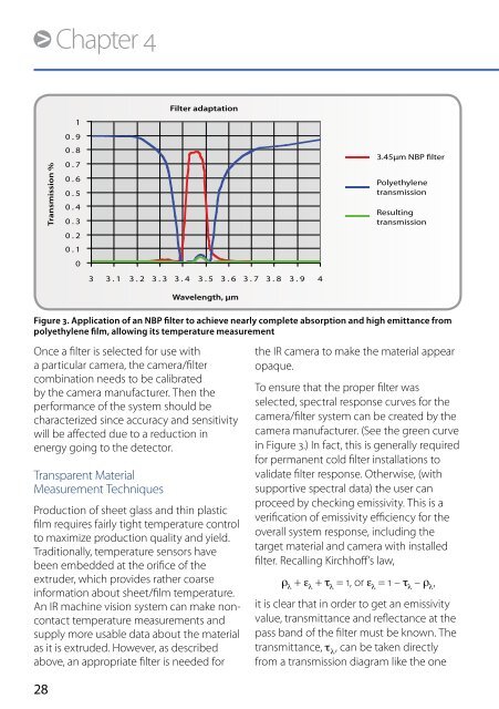
Filter adaptation<br />
3 3.1 3.2 3.3 3.4 3.5 3.6 3.7 3.8 3.9 4<br />
Wavelength, µm<br />
3.45µm NBP filter<br />
Polyethylene<br />
transmission<br />
Resulting<br />
transmission<br />
Figure 3. Application of an NBP filter to achieve nearly complete absorption and high emittance from<br />
polyethylene film, allowing its temperature measurement<br />
Once a filter is selected for use with<br />
a particular camera, the camera/filter<br />
combination needs to be calibrated<br />
by the camera manufacturer. Then the<br />
performance of the system should be<br />
characterized since accuracy and sensitivity<br />
will be affected due to a reduction in<br />
energy going to the detector.<br />
Transparent Material<br />
Measurement Techniques<br />
Production of sheet glass and thin plastic<br />
film requires fairly tight temperature control<br />
to maximize production quality and yield.<br />
Traditionally, temperature sensors have<br />
been embedded at the orifice of the<br />
extruder, which provides rather coarse<br />
information about sheet/film temperature.<br />
An IR machine vision system can make noncontact<br />
temperature measurements and<br />
supply more usable data about the material<br />
as it is extruded. However, as described<br />
above, an appropriate filter is needed for<br />
28<br />
the IR camera to make the material appear<br />
opaque.<br />
To ensure that the proper filter was<br />
selected, spectral response curves for the<br />
camera/filter system can be created by the<br />
camera manufacturer. (See the green curve<br />
in Figure 3.) In fact, this is generally required<br />
for permanent cold filter installations to<br />
validate filter response. Otherwise, (with<br />
supportive spectral data) the user can<br />
proceed by checking emissivity. This is a<br />
verification of emissivity efficiency for the<br />
overall system response, including the<br />
target material and camera with installed<br />
filter. Recalling Kirchhoff’s law,<br />
r l<br />
+ e l<br />
+ t l<br />
= 1, or e l<br />
= 1 – t l<br />
– r l<br />
,<br />
it is clear that in order to get an emissivity<br />
value, transmittance and reflectance at the<br />
pass band of the filter must be known. The<br />
transmittance, t l<br />
, can be taken directly<br />
from a transmission diagram like the one