

Understanding NRT- Reading 1- 2 of 2- Radiogaphic Testing A
Understanding nrt reading 1- 2 of 2- radiogaphic testing a
Understanding nrt reading 1- 2 of 2- radiogaphic testing a

You also want an ePaper? Increase the reach of your titles
YUMPU automatically turns print PDFs into web optimized ePapers that Google loves.
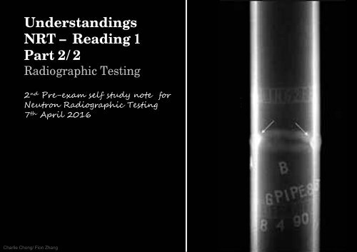
<strong>Understanding</strong>s<br />
<strong>NRT</strong> – <strong>Reading</strong> 1<br />
Part 2/2<br />
Radiographic <strong>Testing</strong><br />
2 nd Pre-exam self study note for<br />
Neutron Radiographic <strong>Testing</strong><br />
7 th April 2016<br />
Charlie Chong/ Fion Zhang
NDT for Upstream<br />
Charlie Chong/ Fion Zhang
NDT for Upstream<br />
Charlie Chong/ Fion Zhang
NDT for Upstream<br />
Charlie Chong/ Fion Zhang
NDT for Upstream<br />
Charlie Chong/ Fion Zhang
Charlie Chong/ Fion Zhang
Charlie Chong/ Fion Zhang<br />
Fion Zhang at Xitang<br />
1 st April 2016
Charlie Chong/ Fion Zhang<br />
SME- Subject Matter Expert<br />
我 们 的 大 学 , 其 实 应 该 聘 请 这 些 能 干 的 退 休 教 授 .<br />
或 许 在 职 的 砖 头 怕 被 排 斥 .<br />
http://cn.bing.com/videos/search?q=Walter+Lewin&FORM=HDRSC3<br />
https://www.youtube.com/channel/UCiEHVhv0SBMpP75JbzJShqw
BOK<br />
NR- Neutron Radiographic <strong>Testing</strong><br />
Length: 4 hours Questions: 135<br />
1. Principles/ Theory<br />
• Nature <strong>of</strong> penetrating radiation<br />
• Interaction between penetrating radiation and matter<br />
• Neutron radiography imaging<br />
• Radiometry<br />
2. Equipment/Materials<br />
• Sources <strong>of</strong> neutrons<br />
• Radiation detectors<br />
• Nonimaging devices<br />
Charlie Chong/ Fion Zhang
3. Techniques/Calibrations<br />
• Blocking and filtering<br />
• Multifilm technique<br />
• Enlargement and projection<br />
• Stereoradiography<br />
• Triangulation methods<br />
• Autoradiography<br />
• Flash Radiography<br />
• In-motion radiography<br />
• Fluoroscopy<br />
• Electron emission radiography<br />
• Microradiography<br />
• Laminography (tomography)<br />
• Control <strong>of</strong> diffraction effects<br />
• Panoramic exposures<br />
•Gaging<br />
• Real time imaging<br />
• Image analysis techniques<br />
Charlie Chong/ Fion Zhang
4. Interpretation/Evaluation<br />
• Image-object relationships<br />
• Material considerations<br />
• Codes, standards, and specifications<br />
5. Procedures<br />
• Imaging considerations<br />
• Film processing<br />
• Viewing <strong>of</strong> radiographs<br />
• Judging radiographic quality<br />
6. Safety and Health<br />
• Exposure hazards<br />
• Methods <strong>of</strong> controlling radiation exposure<br />
• Operation and emergency procedures<br />
Charlie Chong/ Fion Zhang
http://www.yumpu.com/zh/browse/user/charliechong<br />
http://issuu.com/charlieccchong<br />
Charlie Chong/ Fion Zhang
Charlie Chong/ Fion Zhang<br />
http://greekhouse<strong>of</strong>fonts.com/
The Magical Book <strong>of</strong> Tank Inspection ICP<br />
Charlie Chong/ Fion Zhang
Charlie Chong/ Fion Zhang
闭 门 练 功<br />
Charlie Chong/ Fion Zhang
Charlie Chong/ Fion Zhang
Industrial Radiography<br />
Charlie Chong/ Fion Zhang<br />
http://gafoorxspeed.com/industrial-radiography.html
Chapter 6: Radio Isotope (Gamma) Sources<br />
Emitted gamma radiation is one <strong>of</strong> the three types <strong>of</strong> natural radioactivity. It is<br />
the most energetic form <strong>of</strong> electromagnetic radiation, with a very short<br />
wavelength <strong>of</strong> less than one-tenth <strong>of</strong> a nano-meter. Gamma rays are<br />
essentially very energetic x-rays emitted by excited nuclei. They <strong>of</strong>ten<br />
accompany alpha or beta particles, because a nucleus emitting those<br />
particles may be left in an excited (higher-energy) state.<br />
In medicine gamma-ray sources are used to treat cancer, for diagnostic<br />
purposes, and to sterilize equipment and supplies. In industry they are used<br />
in the inspection <strong>of</strong> castings and welds and in food processing to kill<br />
microorganisms and retard spoilage.<br />
Charlie Chong/ Fion Zhang
Man made sources are produced by introducing an extra neutron to atoms <strong>of</strong><br />
the source material. As the material rids itself <strong>of</strong> the neutron, energy is<br />
released in the form <strong>of</strong> gamma rays.<br />
Two <strong>of</strong> the more common industrial Gamma-ray sources are iridium-192 and<br />
cobalt-60. These isotopes emit radiation in two or three discreet wavelengths.<br />
■ Cobalt-60 will emit a 1.33 and a 1.17 MeV gamma ray, and<br />
■ iridium-192 will emit 0.31, 0.47, and 0.60 MeV gamma rays.<br />
Physical size <strong>of</strong> isotope materials will very from manufacturer, but generally<br />
an isotope is a pellet 1.5 mm x 1.5 mm. Depending on the activity (curies)<br />
desired a pellet or pellets are loaded into a stainless steel capsule and sealed<br />
by welding. New sources <strong>of</strong> cobalt will have an activity <strong>of</strong> 20 curies, and new<br />
sources <strong>of</strong> iridium will have an activity <strong>of</strong> 100 curies.<br />
Charlie Chong/ Fion Zhang
Cobalt-60<br />
Charlie Chong/ Fion Zhang
Charlie Chong/ Fion Zhang<br />
https://en.wikipedia.org/wiki/Cobalt-60
Cobalt-60, 60 Co, is a synthetic radioactive isotope <strong>of</strong> cobalt with a half-life<br />
<strong>of</strong> 5.2714 years. It is produced artificially in nuclear reactors. Deliberate<br />
industrial production depends on neutron activation <strong>of</strong> bulk samples <strong>of</strong> the<br />
monoisotopic and mononuclidic cobalt isotope 59 Co.<br />
Measurable quantities are also produced as a by-product <strong>of</strong> typical nuclear<br />
power plant operation and may be detected externally when leaks occur. In<br />
the latter case (in the absence <strong>of</strong> added cobalt) the incidentally produced<br />
60<br />
Co is largely the result <strong>of</strong> multiple stages <strong>of</strong> neutron activation <strong>of</strong> iron<br />
isotopes in the reactor's steel structures via the creation <strong>of</strong> 59 Co precursor.<br />
The simplest case <strong>of</strong> the latter would result from the activation <strong>of</strong> 58 26 Fe.<br />
60<br />
27 Co decays by beta decay to the stable isotope nickel-60 ( 60 28Ni). The<br />
activated nickel nucleus emits two gamma rays with energies <strong>of</strong> 1.17 and<br />
1.33 MeV, hence the overall nuclear equation <strong>of</strong> the reaction is<br />
59<br />
27 Co + n → 60 27 Co → 60 28 Ni + e− + ṽ e + ɣ rays.<br />
Charlie Chong/ Fion Zhang
Activity <strong>of</strong> Co-60<br />
Corresponding to its half-life the radioactive activity <strong>of</strong> one gram <strong>of</strong> 60 Co is 44<br />
TBq (about 1100 curies). The absorbed dose constant is related to the decay<br />
energy and time. For 60 Co it is equal to 0.35 mSv/(GBq h) at one meter from<br />
the source. This allows calculation <strong>of</strong> the equivalent dose, which depends on<br />
distance and activity.<br />
Example: a 60 Co source with an activity <strong>of</strong> 2.8 GBq, which is equivalent to 60<br />
µg <strong>of</strong> pure 60 Co, generates a dose <strong>of</strong> 1 mSv at one meter distance within one<br />
hour. The swallowing <strong>of</strong> 60 Co reduces the distance to a few millimeters, and<br />
the same dose is achieved within seconds.<br />
Test sources, such as those used for school experiments, have an activity <strong>of</strong><br />
Decay <strong>of</strong> Co-60<br />
The decay scheme <strong>of</strong> 60 Co and 60m Co.<br />
The diagram shows a (simplified) decay scheme <strong>of</strong> 60 Co and 60m Co. The main<br />
β-decay transitions are shown. The probability for population <strong>of</strong> the middle<br />
energy level <strong>of</strong> 2.1 MeV by β-decay is 0.0022%, with a maximum energy <strong>of</strong><br />
665.26 keV. Energy transfers between the three levels generate six different<br />
gamma-ray frequencies.<br />
In the diagram the two important ones are marked. Internal conversion<br />
energies are well below the main energy levels.<br />
60m<br />
Co is a nuclear isomer <strong>of</strong> 60Co with a half-life <strong>of</strong> 10.467 minutes. It decays<br />
by internal transition to 60 Co, emitting 58.6 keV gamma rays, or with a low<br />
probability (0.22%) by β-decay into 60 Ni.<br />
Charlie Chong/ Fion Zhang
In the diagram the two important ones are marked. Internal conversion<br />
energies are well below the main energy levels.<br />
Charlie Chong/ Fion Zhang
γ-Ray Spectrum <strong>of</strong> Cobalt-60<br />
Charlie Chong/ Fion Zhang
A nuclear isomer is a metastable state <strong>of</strong> an atomic nucleus caused by<br />
the excitation <strong>of</strong> one or more <strong>of</strong> its nucleons (protons or neutrons).<br />
"Metastable" refers to the fact that these excited states have half-lives more<br />
than 100 to 1000 times the half-lives <strong>of</strong> the excited nuclear states that decay<br />
with a "prompt" half life (ordinarily on the order <strong>of</strong> 10−12 seconds). As a result,<br />
the term "metastable" is usually restricted to refer to isomers with half-lives <strong>of</strong><br />
10−9 seconds or longer. Some sources recommend 5 × 10⁻⁹ s to<br />
distinguish the metastable half life from the normal "prompt" gamma emission<br />
half life<br />
Charlie Chong/ Fion Zhang<br />
https://en.wikipedia.org/wiki/Nuclear_isomer
Isomers<br />
Nuclei can have the same neutron-proton composition but not be identical;<br />
one nucleus can contain more energy than the other. Two nuclei that have<br />
the same composition but varying energy are known as isomers. An example<br />
<strong>of</strong> a pair <strong>of</strong> isomers is shown below. Technetium-99 can exist in two energy<br />
states; the higher <strong>of</strong> the two is a temporary state generally referred to as a<br />
metastable state. The symbol for a nuclide in the metastable state is obtained<br />
by adding the letter m to the mass number (Tc-99m). A nucleus in the<br />
metastable state will eventually give <strong>of</strong>f its excess energy and change to the<br />
other isomer. Such isomeric transitions have an important role in nuclear<br />
medicine and are discussed in detail later.<br />
Charlie Chong/ Fion Zhang<br />
http://www.sprawls.org/ppmi2/MATTER/
Charlie Chong/ Fion Zhang<br />
http://www.sprawls.org/ppmi2/MATTER/
Half-lives (example: Gd)<br />
Charlie Chong/ Fion Zhang
Charlie Chong/ Fion Zhang<br />
Isotope half-lives. Note that the darker more stable<br />
isotope region departs from the line <strong>of</strong> protons (Z) =<br />
neutrons (N), as the element number Z becomes<br />
larger
Advantages <strong>of</strong> gamma ray sources include portability and the ability to<br />
penetrate thick materials in a relativity short time. As can be noted above<br />
cobalt will produce energies comparable to a 1.25 MeV x-ray system. Iridium<br />
will produce energies comparable to a 460 kV x-ray system. Not requiring<br />
electrical sources the gamma radiography is well adapted for use in remote<br />
locations.<br />
■ Co-60 comparable to a 1.25 MeV x-ray system<br />
■ Ir-192 comparable to a 0.46 MeV x-ray system<br />
Disadvantages include shielding requirements and safety considerations.<br />
Depleted uranium is used as a shielding material for sources. The storage<br />
container (camera) for iridium sources will contain 45 pounds <strong>of</strong> shielding<br />
materials. Cobalt will require 500 pounds <strong>of</strong> shielding. Cobalt cameras are<br />
<strong>of</strong>ten fixed to a trailer and transported to and from inspection sites. Iridium is<br />
used whenever possible, and not all companies using source material will<br />
have a cobalt source. Source materials are constantly generating very<br />
penetrating radiation and in a short time considerable damage can be done to<br />
living tissue. Technicians must be trained in potential hazards to themselves<br />
and the public associated with use <strong>of</strong> gamma radiography.<br />
Charlie Chong/ Fion Zhang
Because <strong>of</strong> safety issues source materials are regulated by Federal or State<br />
jurisdictions. The Nuclear Regulation Commission (NRC) has developed and<br />
enforces regulations for source material. The commission allows states to<br />
regulate materials if they follow guidelines <strong>of</strong> the commission. These states<br />
are identified as "Agreement States". In either case, obtaining and<br />
maintaining a license is a costly and well regulated process that protects<br />
workers and the public from the hazards <strong>of</strong> gamma radiation.<br />
Typically gamma radiography is used for inspection <strong>of</strong> castings and<br />
weldments. However, other techniques and applications are being developed.<br />
Pr<strong>of</strong>ile radiography is one example. Pr<strong>of</strong>ile radiography is used for corrosion<br />
under insulation. Exposures are made <strong>of</strong> a small section <strong>of</strong> the pipe wall. A<br />
cooperator block such as a Ricki T is used to calculate the blowout factor for<br />
the exposure in order to calculate the remaining wall thickness <strong>of</strong> the pipe.<br />
The exposure source is usually iridium-192, with cobalt-60 used for the pipes<br />
<strong>of</strong> heavier wall.<br />
Charlie Chong/ Fion Zhang
Radio Isotope - Th232 Half life: 1.405E 10 Years<br />
Radio Isotope - Ir192 Half life: 73.830 Days<br />
Charlie Chong/ Fion Zhang
Radio Isotope - Tm170 Half life: 128.6 Days<br />
Radio Isotope - Yb169 Half life: 32.026 Days<br />
Radio Isotope - Cs137 Half life: 30.07 Years<br />
Charlie Chong/ Fion Zhang
Radio Isotope - Co60 Half life: 1925.1 Days<br />
Charlie Chong/ Fion Zhang
Chapter 7: Radiographic Film<br />
X-ray films for general radiography consist <strong>of</strong> an emulsion-gelatin containing<br />
a radiation sensitive silver halide and a flexible, transparent, blue-tinted base.<br />
The emulsion is different from those used in other types <strong>of</strong> photography films<br />
to account for the distinct characteristics <strong>of</strong> gamma rays and x-rays, but X-ray<br />
films are sensitive to light.<br />
Usually, the emulsion is coated on both sides <strong>of</strong> the base in layers about<br />
0.0005 inch thick (0.0127mm, 12.7μm) . Putting emulsion on both sides <strong>of</strong> the<br />
base doubles the amount <strong>of</strong> radiation-sensitive silver halide, and thus<br />
increases the film speed. The emulsion layers are thin enough so developing,<br />
fixing, and drying can be accomplished in a reasonable time.<br />
A few <strong>of</strong> the films used for radiography only have emulsion on one side which<br />
produces the greatest detail in the image.<br />
Charlie Chong/ Fion Zhang
12.7μm sensitive silver halide<br />
blue-tinted base<br />
When x-rays, gamma rays, or light strike the grains <strong>of</strong> the sensitive silver<br />
halide in the emulsion, a change takes place in the physical structure <strong>of</strong> the<br />
grains. This change is <strong>of</strong> such a nature that it cannot be detected by ordinary<br />
physical methods (latent image) . However, when the exposed film is treated<br />
with a chemical solution (developer), a reaction takes place, causing<br />
formation <strong>of</strong> black, metallic silver. It is this silver, suspended in the gelatin on<br />
both sides <strong>of</strong> the base, that creates an image<br />
Charlie Chong/ Fion Zhang
Film Selection<br />
The selection <strong>of</strong> a film when radiographing any particular component depends<br />
on a number <strong>of</strong> different factors. Listed below are some <strong>of</strong> the factors that<br />
must be considered when selected a film and developing a radiographic<br />
technique.<br />
1. the composition, shape, and size <strong>of</strong> the part being examined and, in some<br />
cases, its weight and location.<br />
2. the type <strong>of</strong> radiation used, whether x-rays from an x-ray generator or<br />
gamma rays from a radioactive source.<br />
3. the kilovoltages available with the x-ray equipment or the intensity <strong>of</strong> the<br />
gamma radiation.<br />
4. the relative importance <strong>of</strong> high radiographic detail or quick and economical<br />
results.<br />
Charlie Chong/ Fion Zhang
Charlie Chong/ Fion Zhang
Charlie Chong/ Fion Zhang
Charlie Chong/ Fion Zhang
Selecting the proper film and developing the optimal radiographic technique<br />
usually involves arriving at a balance between a number <strong>of</strong> opposing factors.<br />
For example, if high resolution and contrast sensitivity is <strong>of</strong> overall importance,<br />
a slower and hence finer grained film should be used in place <strong>of</strong> a faster film.<br />
Charlie Chong/ Fion Zhang
Arithmetic <strong>of</strong> Exposure<br />
RELATIONS OF MILLIAMPERAGE (SOURCE STRENGTH), DISTANCE,<br />
AND TIME<br />
With a given kilovoltage <strong>of</strong> x-radiation or with the gamma radiation from a<br />
particular isotope, the three factors governing the exposure are the<br />
milliamperage (for x-rays) or source strength (for gamma rays), time, and<br />
source-film distance. The numerical relations among these three quantities<br />
are demonstrated below, using x-rays as an example. The same relations<br />
apply for gamma rays, provided the number <strong>of</strong> curies in the source is<br />
substituted wherever milliamperage appears in an equation.<br />
The necessary calculations for any changes in focus-film distance (D),<br />
milliamperage (M), or time (T) are matters <strong>of</strong> simple arithmetic and are<br />
illustrated in the following example. As noted earlier, kilovoltage changes<br />
cannot be calculated directly but must be obtained from the exposure chart <strong>of</strong><br />
the equipment or the operator's logbook.<br />
All <strong>of</strong> the equations shown on these pages can be solved easily for any <strong>of</strong> the<br />
variables (mA, T, D), using one basic rule <strong>of</strong> mathematics: If one factor is<br />
moved across the equals sign (=), it moves from the numerator to the<br />
denominator or vice versa.<br />
Charlie Chong/ Fion Zhang
We can now solve for any unknown by:<br />
1. Eliminating any factor that remains constant (has the same value and is in<br />
the same location on both sides <strong>of</strong> the equation).<br />
2. Simplifying the equation by moving the unknown value so that it is alone<br />
on one side <strong>of</strong> the equation in the numerator.<br />
3. Substituting the known values and solving the equation.<br />
Charlie Chong/ Fion Zhang
Milliamperage-Distance Relation<br />
The milliamperage employed in any exposure technique should be in<br />
conformity with the manufacturer's rating <strong>of</strong> the x-ray tube. In most<br />
laboratories, however, a constant value <strong>of</strong> milliamperage is usually adopted<br />
for convenience.<br />
Rule: The milliamperage (M) required for a given exposure is directly<br />
proportional to the square <strong>of</strong> the focus-film distance (D). The equation is<br />
expressed as follows:<br />
Charlie Chong/ Fion Zhang
Example: Suppose that with a given exposure time and kilovoltage, a<br />
properly exposed radiograph is obtained with 5mA (M1) at a distance <strong>of</strong><br />
12 inches (D1), and that it is desired to increase the sharpness <strong>of</strong> detail in the<br />
image by increasing the focus-film distance to 24 inches (D2). The correct<br />
milliamperage (M2) to obtain the desired radiographic density at the<br />
increased distance (D2) may be computed from the proportion:<br />
Charlie Chong/ Fion Zhang
When very low kilovoltages, say 20 kV or less, are used, the x-ray intensity<br />
decreases with distance more rapidly than calculations based on the inverse<br />
square law would indicate because <strong>of</strong> absorption <strong>of</strong> the x-rays by the air. Most<br />
industrial radiography, however, is done with radiation so penetrating that the<br />
air absorption need not be considered. These comments also apply to the<br />
time-distance relations discussed below.<br />
Charlie Chong/ Fion Zhang
Time-Distance Relation<br />
Rule: The exposure time (T) required for a given exposure is directly<br />
proportional to the square <strong>of</strong> the focus-film distance (D). Thus:<br />
To solve for either a new Time (T2) Or a new Distance (D2), simply follow the<br />
steps shown in the example above.<br />
Charlie Chong/ Fion Zhang
Tabular Solution <strong>of</strong> Milliamperage-Time and Distance Problems<br />
Problems <strong>of</strong> the types discussed above may also be solved by the use <strong>of</strong> a<br />
table similar to the one below. The factor between the new and the old<br />
exposure time, milliamperage, or milliamperage-minute (mA-min) value<br />
appears in the box at the intersection <strong>of</strong> the column for the new source-film<br />
distance and the row for the old source-film distance.<br />
Suppose, for example, a properly exposed radiograph has an exposure <strong>of</strong> 20<br />
mA-min with a source-film distance <strong>of</strong> 30 inches and you want to increase the<br />
source-film distance to 45 inches in order to decrease the geometric<br />
unsharpness in the radiograph. The factor appearing in the box at the<br />
intersection <strong>of</strong> the column for 45 inches (new source-film distance) and the<br />
row for 30 inches (old source-film distance) is 2.3. Multiply the old<br />
milliampere-minute value (20) by 2.3 to give the new value--46 mA-min.<br />
Charlie Chong/ Fion Zhang
Note that some approximation is involved in the use <strong>of</strong> such a table, since the<br />
values in the boxes are rounded <strong>of</strong>f to two significant figures. However, the<br />
errors involved are always less than 5 percent and, in general, are<br />
insignificant in actual practice.<br />
Further, a table like the one below obviously cannot include all source-film<br />
distances, because <strong>of</strong> limitations <strong>of</strong> space. However, in any one radiographic<br />
department, only a few source-film distances are used in the great bulk <strong>of</strong> the<br />
work, and a table <strong>of</strong> reasonable size can be constructed involving only these<br />
few distances.<br />
Charlie Chong/ Fion Zhang
Milliamperage-Time and Distance Relations<br />
Charlie Chong/ Fion Zhang
Milliamperage-Time Relation<br />
Rule: The milliamperage (M) required for a given exposure is inversely<br />
proportional to the time (T):<br />
Another way <strong>of</strong> expressing this is to say that for a given set <strong>of</strong> conditions<br />
(voltage, distance, etc), the product <strong>of</strong> milliamperage and time is constant for<br />
the same photographic effect.<br />
Thus, M1T1 = M2T2 = M3T3 = C, a constant.<br />
This is commonly referred to as the reciprocity law. (Important exceptions are<br />
discussed below.)<br />
To solve for either a new time (T2) or a new milliamperage (M2), simply follow<br />
the steps shown in the example in "Milliamperage-Distance Relation".<br />
Charlie Chong/ Fion Zhang
THE RECIPROCITY LAW<br />
In the sections immediately preceding, it has been assumed that exact<br />
compensation for a decrease in the time <strong>of</strong> exposure can be made by<br />
increasing the milliamperage according to the relation M1T1 = M2T2. This<br />
may be written MT = C and is an example <strong>of</strong> the general photochemical law<br />
that the same effect is produced for IT = constant, where I is intensity <strong>of</strong> the<br />
radiation and T is the time <strong>of</strong> exposure. It is called the reciprocity law and is<br />
true for direct x-ray and lead screen exposures. For exposures to light, it is<br />
not quite accurate and, since some radiographic exposures are made with the<br />
light from fluorescent intensifying screens, the law cannot be strictly applied.<br />
Errors as the result <strong>of</strong> assuming the validity <strong>of</strong> the reciprocity law are usually<br />
so small that they are not noticeable in examples <strong>of</strong> the types given in the<br />
preceding sections. Departures may be apparent, however, if the intensity is<br />
changed by a factor <strong>of</strong> 4 or more. Since intensity may be changed by<br />
changing the source-film distance, failure <strong>of</strong> the reciprocity law may appear to<br />
be a violation <strong>of</strong> the inverse square law.<br />
Charlie Chong/ Fion Zhang
Applications <strong>of</strong> the reciprocity law over a wide intensity range sometimes<br />
arise, and the relation between results and calculations may be misleading<br />
unless the possibility <strong>of</strong> failure <strong>of</strong> the reciprocity law is kept in mind. Failure <strong>of</strong><br />
the reciprocity law means that the efficiency <strong>of</strong> a light-sensitive emulsion in<br />
utilizing the light energy depends on the light intensity. Under the usual<br />
conditions <strong>of</strong> industrial radiography, the number <strong>of</strong> milliampere-minutes<br />
required for a properly exposed radiograph made with fluorescent intensifying<br />
screens increases as the x-ray intensity decreases, because <strong>of</strong> reciprocity<br />
failure.<br />
If the milliamperage remains constant and the x-ray intensity is varied by<br />
changing the focus-film distance, the compensating changes shown in the<br />
table below should be made in the exposure time.<br />
Charlie Chong/ Fion Zhang
Approximate Corrections for Reciprocity Law Failure<br />
1<br />
Column 2 shows the changes necessitated by the inverse square law only.<br />
Column 3 shows the combined effects <strong>of</strong> the inverse square law and failure <strong>of</strong><br />
the reciprocity law.<br />
Charlie Chong/ Fion Zhang
The table gives a rough estimate <strong>of</strong> the deviations from the rules given in the<br />
foregoing section that are necessitated by failure <strong>of</strong> the reciprocity law for<br />
exposures with fluorescent intensifying screens. It must be emphasized that<br />
the figures in column 3 are only approximate. The exact values <strong>of</strong> the factors<br />
vary widely with the intensity <strong>of</strong> the fluorescent light and with the density <strong>of</strong><br />
the radiograph.<br />
When distance is held constant, the milliamperage may be increased or<br />
decreased by a factor <strong>of</strong> 2, and the new exposure time may be calculated by<br />
the method shown in "Time-Distance Relation", without introducing errors<br />
caused by failure <strong>of</strong> the reciprocity law, which are serious in practice.<br />
Charlie Chong/ Fion Zhang<br />
http://webstag.kodak.cz/US/en/business/aim/industrial/ndt/literature/radiography/07.shtml#ccurves
Film Packaging<br />
Radiographic film can be purchased in a number <strong>of</strong> different packaging<br />
options. The most basic form is as individual sheets in a box. In preparation<br />
for use, each sheet must be loaded into a cassette or film holder in the<br />
darkroom to protect it from exposure to light. The sheet are available in a<br />
variety <strong>of</strong> sizes and can be purchased with or without interleaving paper.<br />
Interleaved packages have a layer <strong>of</strong> paper that separates each piece <strong>of</strong> film.<br />
The interleaving paper is removed before the film is loaded into the film<br />
holder. Many users find the interleaving paper useful in separating the sheets<br />
<strong>of</strong> film and <strong>of</strong>fer some protection against scratches and dirt during handling.<br />
Industrial x-ray films are also available in a form in which each sheet is<br />
enclosed in a light-tight envelope. The film can be exposed from either side<br />
without removing it from the protective packaging. A rip strip makes it easy to<br />
remove the film in the darkroom for processing. This form <strong>of</strong> packaging has<br />
the advantage <strong>of</strong> eliminating the process <strong>of</strong> loading the film holders in the<br />
darkroom. The film is completely protected from finger marks and dirt until the<br />
time the film is removed from the envelope for processing.<br />
Charlie Chong/ Fion Zhang
Packaged film is also available in rolls, which allows the radiographer to cut<br />
the film to any length. The ends <strong>of</strong> the packaging are sealed with electrical<br />
tape in the darkroom. In applications such as the radiography <strong>of</strong><br />
circumferential welds and the examination <strong>of</strong> long joints on an aircraft<br />
fuselage, long lengths <strong>of</strong> film <strong>of</strong>fer great economic advantage. The film is<br />
wrapped around the outside <strong>of</strong> a structure and the radiation source is<br />
positioned on axis inside allowing for examination <strong>of</strong> a large area with a single<br />
exposure.<br />
Envelope packaged film can be purchased with the film sandwiched between<br />
two lead oxide screens. The screens function to reduce scatter radiation at<br />
energy levels below 150kV and as intensification screens above 150 kV.<br />
Charlie Chong/ Fion Zhang
Film Handling<br />
X-ray film should always be handled carefully to avoid physical strains, such<br />
as pressure, creasing, buckling, friction, etc. Whenever films are loaded in<br />
semiflexible holders and external clamping devices are used, care should be<br />
taken to be sure pressure is uniform. If a film holder bears against a few high<br />
spots, such as on an un-ground weld, the pressure may be great enough to<br />
produce desensitized areas in the radiograph. This precaution is particularly<br />
important when using envelope-packed films.<br />
Marks resulting from contact with fingers that are moist or contaminated with<br />
processing chemicals, as well as crimp marks, are avoided if large films are<br />
always grasped by the edges and allowed to hang free. A supply <strong>of</strong> clean<br />
towels should be kept close at hand as an incentive to dry the hands <strong>of</strong>ten<br />
and well. Use <strong>of</strong> envelope-packed films avoids many <strong>of</strong> these problems until<br />
the envelope is opened for processing.<br />
Another important precaution is to avoid drawing film rapidly from cartons,<br />
exposure holders, or cassettes. Such care will help to eliminate circular or<br />
treelike black markings in the radiograph that sometimes result due to static<br />
electric discharges.<br />
Charlie Chong/ Fion Zhang
Chapter 8: Image Considerations<br />
The most common detector used in industrial radiography is film. The high<br />
sensitivity to ionizing radiation provides excellent detail and sensitivity to<br />
density changes when producing images <strong>of</strong> industrial materials. Image quality<br />
is determined by a combination <strong>of</strong> variables: radiographic contrast and<br />
definition. Many variables affecting radiographic contrast and definition are<br />
summarized below and addressed in following sections.<br />
Radiographic Contrast<br />
Radiographic contrast describes the differences in photographic density in a<br />
radiograph. The contrast between different parts <strong>of</strong> the image is what forms<br />
the image and the greater the contrast, the more visible features become.<br />
Radiographic contrast has two main contributors: subject contrast and<br />
detector or film contrast.<br />
Charlie Chong/ Fion Zhang
Subject contrast is determined by the following variables:<br />
- Absorption differences in the specimen<br />
- Wavelength <strong>of</strong> the primary radiation<br />
-Scatter or secondary radiation<br />
Film contrast is determined by the following:<br />
- Grain size or type <strong>of</strong> film<br />
- Chemistry <strong>of</strong> film processing chemicals<br />
- Concentrations <strong>of</strong> film processing chemicals<br />
- Time <strong>of</strong> development<br />
- Temperature <strong>of</strong> development<br />
- Degree <strong>of</strong> mechanical agitation (physical motion)<br />
Charlie Chong/ Fion Zhang
Exposing the film to produce higher film densities will generally increase<br />
contrast. In other words, darker areas will increase in density faster than<br />
lighter areas because in any given period <strong>of</strong> time more x-rays are reaching<br />
the darker areas. Lead screens in the thickness range <strong>of</strong> 0.004 to 0.015 inch<br />
typically reduce scatter radiation at energy levels below 150, 000 volts. Above<br />
this point they will emit electrons to provide more exposure <strong>of</strong> the film to<br />
ionizing radiation thus increasing the density <strong>of</strong> the radiograph. Fluorescent<br />
screens produce visible light when exposed to radiation and this light further<br />
exposes the film.<br />
Charlie Chong/ Fion Zhang
Definition<br />
Radiographic definition is the abruptness <strong>of</strong> change in going from one density<br />
to another. There are a number <strong>of</strong> geometric factors <strong>of</strong> the X-ray equipment<br />
and the radiographic setup that have an effect on definition. These geometric<br />
factors include:<br />
1. Focal spot size, which is the area <strong>of</strong> origin <strong>of</strong> the radiation. The focal spot size<br />
should be as close to a point source as possible to produce the most definition.<br />
2. Source to film distance, which is the distance from the source to the part. Definition<br />
increases as the source to film distance increase.<br />
3. Specimen to detector (film) distance, which is the distance between the specimen<br />
and the detector. For optimal definition, the specimen and detector should be as<br />
close together as possible. .<br />
4. Abrupt changes in specimen thickness may cause distortion on the radiograph.<br />
5. Movement <strong>of</strong> the specimen during the exposure will produce distortion on the<br />
radiograph.<br />
6. Film graininess, and screen mottling will decrease definition. The grain size <strong>of</strong> the<br />
film will affect the definition <strong>of</strong> the radiograph. Wavelength <strong>of</strong> the radiation will<br />
influence apparent graininess. As the wavelength shortens and penetration<br />
increases, the apparent graininess <strong>of</strong> the film will increase. Also, increased<br />
development <strong>of</strong> the film will increase the apparent graininess <strong>of</strong> the radiograph.<br />
Charlie Chong/ Fion Zhang
Chapter 9: Film Processing<br />
Processing film is a strict science governed by rigid rules <strong>of</strong> chemical<br />
concentration, temperature, time, and physical movement. Whether<br />
processing is done by hand or automatically by machine, excellent<br />
radiographs require the highest possible degree <strong>of</strong> consistency and quality<br />
control.<br />
Manual Processing & Darkrooms<br />
Manual processing begins with the darkroom. The darkroom should be<br />
located in a central location, adjacent to the reading room and a reasonable<br />
distance from the exposure area. For portability darkrooms are <strong>of</strong>ten mounted<br />
on pickups or trailers.<br />
Charlie Chong/ Fion Zhang
Film should be located in a light, tight compartment, which is most <strong>of</strong>ten a<br />
metal bin that is used to store and protect the film. An area next to the film bin<br />
that is dry and free <strong>of</strong> dust and dirt should be used to load and unload the film.<br />
While another area, the wet side, will be used to process the film. Thus<br />
protecting the film from any water or chemicals that may be located on the<br />
surface <strong>of</strong> the wet side.<br />
Each <strong>of</strong> step in film processing must be excited properly to develop the image,<br />
wash out residual processing chemicals, and to provide adequate shelf life <strong>of</strong><br />
the radiograph. The objective <strong>of</strong> processing is two fold. First to produce a<br />
radiograph adequate for viewing, and secondly to prepare the radiograph for<br />
archival storage. A radiograph may be retrieved after 5 or even 20 years in<br />
storage.<br />
Charlie Chong/ Fion Zhang
Automatic Processor Evaluation<br />
The automatic processor is the essential piece <strong>of</strong> equipment in every x-ray<br />
department. The automatic processor will reduce film processing time when<br />
compared to manual development by a factor <strong>of</strong> four. To monitor the<br />
performance <strong>of</strong> a processor, apart from optimum temperature and mechanical<br />
checks, chemical and sensitometric checks should be performed for<br />
developer and fixer. Chemical checks involve measurement <strong>of</strong> pH values for<br />
developer and replenisher, fixer and replenisher, measurement <strong>of</strong> specific<br />
gravity and fixer silver levels. Ideally pH should be measured daily and it is<br />
important to record these measurements, as regular logging provides very<br />
useful information. The daily measurements <strong>of</strong> pH values for developer and<br />
fixer can then be plotted to observe the trend <strong>of</strong> variations in these values<br />
compared to normal pH operating levels to identify problems.<br />
Charlie Chong/ Fion Zhang
Sensitometric checks may be carried out to evaluate if the performance <strong>of</strong><br />
films in the automatic processors is being maximized. These checks involve<br />
measurement <strong>of</strong> basic fog level, speed and average gradient made at 1° C<br />
intervals <strong>of</strong> temperature. The range <strong>of</strong> temperature measurement depends on<br />
the type <strong>of</strong> chemistry in use, whether cold or hot developer. These three<br />
measurements: fog level, speed, and average gradient, should then be<br />
plotted against temperature and compared with the manufacturer's supplied<br />
figures.<br />
Charlie Chong/ Fion Zhang
Chapter 10: Viewing Radiographs<br />
Radiographs (developed film exposed to x-ray or gamma radiation) are<br />
generally viewed on a light-box. However, it is becoming increasingly<br />
common to digitize radiographs and view them on a high resolution monitor.<br />
Proper viewing conditions are very important when interpreting a radiograph.<br />
The viewing conditions can enhance or degrade the subtle details <strong>of</strong><br />
radiographs.<br />
Viewing Radiographs<br />
Before beginning the evaluation <strong>of</strong> a radiograph, the viewing equipment and<br />
area should be considered. The area should be clean and free <strong>of</strong> distracting<br />
materials. Magnifying aids, masking aids, and film markers should be close at<br />
hand. Thin cotton gloves should be available and worn to prevent fingerprints<br />
on the radiograph. Ambient light levels should be low. Ambient light levels <strong>of</strong><br />
less than 2 fc are <strong>of</strong>ten recommended, but subdued lighting, rather than total<br />
darkness, is preferable in the viewing room. The brightness <strong>of</strong> the<br />
surroundings should be about the same as the area <strong>of</strong> interest in the<br />
radiograph. Room illumination must be arranged so that there are no<br />
reflections from the surface <strong>of</strong> the film under examination.<br />
Charlie Chong/ Fion Zhang
Film viewers should be clean and in good working condition. There are four<br />
groups <strong>of</strong> film viewers. These include: strip viewers, area viewers, spot<br />
viewers, and a combination <strong>of</strong> spot and area viewers. Film viewers should<br />
provide a source <strong>of</strong> defused, adjustable, and relativity cool light as heat from<br />
viewers can cause distortion <strong>of</strong> the radiograph. A film having a measured<br />
density <strong>of</strong> 2.0 will allow only 1.0 percent <strong>of</strong> the incident light to pass. A film<br />
containing a density <strong>of</strong> 4.0 will allow only 0.01 percent <strong>of</strong> the incident light to<br />
pass. With such low levels <strong>of</strong> light passing through the radiograph the delivery<br />
<strong>of</strong> a good light source is important.<br />
The radiographic process should be performed in accordance with a written<br />
procedure or code, or as required by contractual documents. The required<br />
documents should be available in the viewing area and referenced as<br />
necessary when evaluating components. Radiographic film quality and<br />
acceptability, as required by the procedure, should first be determined.<br />
Charlie Chong/ Fion Zhang
It should be verified that the radiograph was produced to the correct density<br />
on the required film type, and that it contains the correct identification<br />
information. It should also be verified that the proper image quality indicator<br />
was used and that the required sensitivity level was met. Next, the radiograph<br />
should be checked to ensure that it does not contain processing and handling<br />
artifacts that could mask discontinuities or other details <strong>of</strong> interest. The<br />
technician should develop a standard process for evaluating the radiographs<br />
so that details are not overlooked.<br />
Once a radiograph passes these initial checks it is ready for interpretation.<br />
Radiographic film interpretation is an acquired skill combining, visual acuity<br />
with knowledge <strong>of</strong> materials, manufacturing processes, and their associated<br />
discontinues. If the component is inspected while in service, an<br />
understanding <strong>of</strong> applied loads and history <strong>of</strong> the component is helpful. A<br />
process for viewing radiographs, left to right top to bottom etc., is helpful and<br />
will prevent overlooking an area on the radiograph. This process is <strong>of</strong>ten<br />
developed over time and individualized. One part <strong>of</strong> the interpretation process,<br />
sometimes overlooked, is rest. The mind as well as the eyes need to<br />
occasionally rest when interpreting radiographs.<br />
Charlie Chong/ Fion Zhang
When viewing a particular region <strong>of</strong> interest, techniques such as using a small<br />
light source and moving the radiograph over the small light source, or<br />
changing the intensity <strong>of</strong> the light source will help the radiographer identify<br />
relevant indications. Magnifying tools should also be used when appropriate<br />
to help identify and evaluate indications. Viewing the actual component being<br />
inspected is very <strong>of</strong>ten helpful in developing an understanding <strong>of</strong> the details<br />
seen in a radiograph.<br />
Interpretation <strong>of</strong> radiographs is an acquired skill that is perfected over time.<br />
By using the proper equipment and developing consistent evaluation<br />
processes, the interpreter will increase his or her probability <strong>of</strong> detecting<br />
defects.<br />
Charlie Chong/ Fion Zhang
Chapter 11: Contrast and Definition<br />
The first subjective criteria for determining radiographic quality is radiographic<br />
contrast. Essentially, radiographic contrast is the degree <strong>of</strong> density difference<br />
between adjacent areas on a radiograph.<br />
It is entirely possible to radiograph a particular subject and, by varying factors,<br />
produce two radiographs possessing entirely different contrast levels. With an<br />
x-ray source <strong>of</strong> low kilovoltage, we see an illustration <strong>of</strong> extremely high<br />
radiographic contrast, that is, density difference between the two adjacent<br />
areas (A and B) is high. It is essential that sufficient contrast exist between<br />
the defect <strong>of</strong> interest and the surrounding area. There is no viewing technique<br />
that can extract information that does not already exist in the original<br />
radiograph.<br />
With an x-ray source <strong>of</strong> high kilovoltage, we see a sample <strong>of</strong> relatively low<br />
radiographic contrast, that is, the density difference between the two adjacent<br />
areas (A and B) is low.<br />
Charlie Chong/ Fion Zhang
Radiographic Contrast<br />
Charlie Chong/ Fion Zhang
Definition<br />
Besides radiographic contrast as a subjective criteria for determining<br />
radiographic quality, there exists one other, radiographic detail. Essentially,<br />
radiographic definition is the abruptness <strong>of</strong> change in going from one density<br />
to another. For example, it is possible to radiograph a particular subject and,<br />
by varying certain factors, produce two radiographs which possess different<br />
degrees <strong>of</strong> definition.<br />
In the example to the left, a two-step step tablet with the transition from step<br />
to step represented by Line BC is quite sharp or abrupt. Translated into a<br />
radiograph, we see that the transition from the high density to the low density<br />
is abrupt. The Edge Line BC is still a vertical line quite similar to the step<br />
tablet itself. We can say that the detail portrayed in the radiograph is<br />
equivalent to physical change present in the step tablet. Hence, we can say<br />
that the imaging system produced a faithful visual reproduction <strong>of</strong> the step<br />
table. It produced essentially all <strong>of</strong> the information present in the step tablet<br />
on the radiograph.<br />
Charlie Chong/ Fion Zhang
In the example on the right, the same two-step step tablet has been<br />
radiographed. However, here we note that, for some reason, the imaging<br />
system did not produce a faithful visual reproduction. The Edge Line BC on<br />
the step tablet is not vertical. This is evidenced by the gradual transition<br />
between the high and low density<br />
Charlie Chong/ Fion Zhang
areas on the radiograph. The edge definition or detail is not present because<br />
<strong>of</strong> certain factors or conditions which exist in the imaging system.<br />
In review, it is entirely possible to have radiographs with the following<br />
qualities:<br />
■ Low contrast and poor detail<br />
■ High contrast and poor definition<br />
■ Low contrast and good definition<br />
■ High contrast and good definition<br />
One must bear in mind that radiographic contrast and definition are not<br />
dependent upon the same set <strong>of</strong> factors. If detail in a radiograph is originally<br />
lacking, then attempts to manipulate radiographic contrast will have no effect<br />
on the amount <strong>of</strong> detail present in that radiograph<br />
Charlie Chong/ Fion Zhang
Chapter 12: Radiographic Density<br />
Film speed, gradient, and graininess are all responsible for the performance<br />
<strong>of</strong> the film during exposure and processing. As these combine with<br />
processing variables a final product or the radiograph is produced. In viewing<br />
the radiograph, requirements have been established for acceptable<br />
radiographs in industry. The density <strong>of</strong> a radiograph in industry will determine<br />
if further viewing is possible.<br />
Density considerations date back to early day radiography. Hurder and<br />
Drifield have been credited with developing much <strong>of</strong> the early information on<br />
the characteristic curve and density <strong>of</strong> a radiograph. Codes and standards will<br />
typically require densities <strong>of</strong> a radiograph to be maintained between 1.8 to 4.0<br />
H&D (Hurder and Drifield) for acceptable viewing. As density increases,<br />
contrast will also increase.<br />
Charlie Chong/ Fion Zhang
This is true above 4.0 H&D, however as density reaches 4.0 H&D an<br />
extremely bright viewing light is necessary for evaluation.<br />
Density, technically should be stated "Transmitted Density" when associated<br />
with transparent-base film. This density is the log <strong>of</strong> the intensity <strong>of</strong> light<br />
incident on the film to the intensity <strong>of</strong> light transmitted through the film. A<br />
density reading <strong>of</strong> 2.0 H&D is the result <strong>of</strong> only 1 percent <strong>of</strong> the transmitted<br />
light reaching the sensor. At 4.0 H&D only 0.01% <strong>of</strong> transmitted light reaches<br />
the far side <strong>of</strong> the film.<br />
Charlie Chong/ Fion Zhang
Chapter 13: Controlling Radiographic Quality<br />
One <strong>of</strong> the methods <strong>of</strong> controlling the quality <strong>of</strong> a radiograph is through the<br />
use <strong>of</strong> image quality indicators (IQI). IQIs provide a means <strong>of</strong> visually<br />
informing the film interpreter <strong>of</strong> the contrast sensitivity and definition <strong>of</strong> the<br />
radiograph. The IQI indicates that a specified amount <strong>of</strong> material thickness<br />
change will be detectable in the radiograph, and that the radiograph has a<br />
certain level <strong>of</strong> definition so that the density changes are not lost due to<br />
unsharpness. Without such a reference point, consistency and quality could<br />
not be maintained and defects could go undetected.<br />
Image quality indicators take many shapes and forms due to the various<br />
codes or standards that invoke their use. In the United States two IQI styles<br />
are prevalent; the placard, or hole-type and the wire IQI. IQIs comes in a<br />
variety <strong>of</strong> material types so that one with radiation absorption characteristics<br />
similar to the material being radiographed can be used.<br />
Charlie Chong/ Fion Zhang
Charlie Chong/ Fion Zhang
Hole-Type IQIs<br />
ASTM Standard E1025 gives detailed requirements for the design and<br />
material group classification <strong>of</strong> hole-type image quality indicators. E1025<br />
designates eight groups <strong>of</strong> shims based on their radiation absorption<br />
characteristics. A notching system is incorporated into the requirements<br />
allowing the radiographer to easily determine if the penetrameter is the<br />
correct material type for the product. The thickness in thousands <strong>of</strong> an inch is<br />
noted on each pentameter by a lead number 0.250 to 0.375 inch wide<br />
depending on the thickness <strong>of</strong> the shim. Military or Government standards<br />
require a similar penetrameter but use lead letters to indicate the material<br />
type rather than notching system as shown on the left in the image above.<br />
Image quality levels are typically designated using a two part expression such<br />
as 2-2T. The first term refers to the IQI thickness expressed as a percentage<br />
<strong>of</strong> the region <strong>of</strong> interest <strong>of</strong> the part being inspected. The second term in the<br />
expression refers to the diameter <strong>of</strong> the hole that must be revealed and it is<br />
expressed as a multiple <strong>of</strong> the IQI thickness. Therefore, a 2-2T call-out would<br />
mean that the shim thickness should be two percent <strong>of</strong> material thickness and<br />
that a hole that is twice the IQI thickness must be detectable on the<br />
radiograph. This presentation <strong>of</strong> a 2-2T IQI in the radiograph verifies<br />
Charlie Chong/ Fion Zhang
that the radiographic technique is capable <strong>of</strong> showing a material loss <strong>of</strong> 2% in<br />
the area <strong>of</strong> interest.It should be noted that even if 2-2T sensitivity is indicated<br />
on a radiograph, a defect <strong>of</strong> the same diameter and material loss may not be<br />
visible. The holes in the penetrameter represent sharp boundaries, and a<br />
small thickness change. Discontinues within the part may contain gradual<br />
changes, and are <strong>of</strong>ten less visible. The penetrameter is used to indicate<br />
quality <strong>of</strong> the radiographic technique and not intended to be used as a<br />
measure <strong>of</strong> size <strong>of</strong> cavity that can be located on the radiograph.<br />
Charlie Chong/ Fion Zhang
Wire Penetrameters<br />
ASTM Standard E747 covers the radiographic examination <strong>of</strong> materials using<br />
wire penetrameters (IQIs) to control image quality. Wire IQIs consist <strong>of</strong> a set<br />
<strong>of</strong> six wires arranged in order <strong>of</strong> increasing diameter and encapsulated<br />
between two sheets <strong>of</strong> clear plastic. E747 specifies four wire IQIs sets, which<br />
control the wire diameters. The set letter (A, B, C or D) is shown in the lower<br />
right corner <strong>of</strong> the IQI. The number in the lower left corner indicates the<br />
material group. The same image quality levels and expressions (i.e. 2-2T)<br />
used for hole-type IQIs are typically also used for wire IQIs. The wire sizes<br />
that correspond to various hole-type quality levels can be found in a table in<br />
E747 or can be calculated using the following formula.<br />
Where:<br />
F = 0.79 (constant form factor for wire)<br />
D = wire diameter (mm or inch)<br />
L = 7.6 mm or 0.3 inch (effective length <strong>of</strong> wire)<br />
T = Hole-type IQI thickness (mm or inch)<br />
H = Hole-type IQI hole diameter (mm or inch)<br />
Charlie Chong/ Fion Zhang
Placement <strong>of</strong> IQIs<br />
IQIs should be placed on the source side <strong>of</strong> the part over a section with a<br />
material thickness equivalent to the region <strong>of</strong> interest. If this is not possible,<br />
the IQI may be placed on a block <strong>of</strong> similar material and thickness to the<br />
region <strong>of</strong> interest. When a block is used, the IQI should the same distance<br />
from the film as it would be if placed directly on the part in the region <strong>of</strong><br />
interest. The IQI should also be placed slightly away from the edge <strong>of</strong> the part<br />
so that atleast three <strong>of</strong> its edges are visible in the radiograph.<br />
Charlie Chong/ Fion Zhang
Chapter 14: Exposure Calculations<br />
Properly exposing a radiograph is <strong>of</strong>ten a trial and error process, as there are<br />
many variables that affect the final radiograph. In this section we make the<br />
assumptions <strong>of</strong> a generic (and fixed characteristic) x-ray source, fixed film<br />
type, and fixed quality <strong>of</strong> development.<br />
The applet below estimates the density <strong>of</strong> the radiograph based on material,<br />
thickness, geometry, energy (voltage), current, and, <strong>of</strong> course, time. The<br />
effect <strong>of</strong> the energy and the physical setup are shown by looking at the film<br />
density after exposure. It should be noted that the applet will differ<br />
considerably from industrial x-ray configurations, and is designed for<br />
demonstration <strong>of</strong> variables in an x-ray system.<br />
Charlie Chong/ Fion Zhang
Chapter 15: Radiograph Interpretation - Welds<br />
In addition to producing high quality radiographs, the radiographer must also<br />
be skilled in radiographic interpretation. Interpretation <strong>of</strong> radiographs takes<br />
place in three basic steps which are (1) detection, (2) interpretation, and (3)<br />
evaluation. All <strong>of</strong> these steps make use <strong>of</strong> the radiographer's visual acuity.<br />
Visual acuity is the ability to resolve a spatial pattern in an image. The ability<br />
<strong>of</strong> an individual to detect discontinuities in radiography is also affected by the<br />
lighting condition in the place <strong>of</strong> viewing, and the experience level for<br />
recognizing various features in the image. The following material was<br />
developed to help students develop an understanding <strong>of</strong> the types <strong>of</strong> defects<br />
found in weldments and how they appear in a radiograph.<br />
Discontinuities<br />
Discontinuities are interruptions in the typical structure <strong>of</strong> a material. These<br />
interruptions may occur in the base metal, weld material or "heat affected"<br />
zones. Discontinuities, which do not meet the requirements <strong>of</strong> the codes or<br />
specification used to invoke and control an inspection, are referred to as<br />
defects.<br />
Charlie Chong/ Fion Zhang
General Welding Discontinuities<br />
The following discontinuities are typical <strong>of</strong> all types <strong>of</strong> welding.<br />
Cold lap is a condition where the weld filler metal does not properly fuse with<br />
the base metal or the previous weld pass material (interpass cold lap). The<br />
arc does not melt the base metal sufficiently and causes the slightly molten<br />
puddle to flow into base material without bonding.<br />
Charlie Chong/ Fion Zhang
Porosity is the result <strong>of</strong> gas entrapment in the solidifying metal. Porosity can<br />
take many shapes on a radiograph but <strong>of</strong>ten appears as dark round or<br />
irregular spots or specks appearing singularly, in clusters or rows. Sometimes<br />
porosity is elongated and may have the appearance <strong>of</strong> having a tail This is<br />
the result <strong>of</strong> gas attempting to escape while the metal is still in a liquid state<br />
and is called wormhole porosity. All porosity is a void in the material it will<br />
have a radiographic density more than the surrounding area.<br />
Charlie Chong/ Fion Zhang
Cluster porosity is caused when flux coated electrodes are contaminated<br />
with moisture. The moisture turns into gases when heated and becomes<br />
trapped in the weld during the welding process. Cluster porosity appear just<br />
like regular porosity in the radiograph but the indications will be grouped close<br />
together.<br />
Charlie Chong/ Fion Zhang
Slag inclusions are nonmetallic solid material entrapped in weld metal or<br />
between weld and base metal. In a radiograph, dark, jagged asymmetrical<br />
shapes within the weld or along the weld joint areas are indicative <strong>of</strong> slag<br />
inclusions.<br />
Charlie Chong/ Fion Zhang
Incomplete penetration (IP) or lack <strong>of</strong> penetration (LOP) occurs when the<br />
weld metal fails to penetrate the joint. It is one <strong>of</strong> the most objectionable weld<br />
discontinuities. Lack <strong>of</strong> penetration allows a natural stress riser from which a<br />
crack may propagate. The appearance on a radiograph is a dark area with<br />
well-defined, straight edges that follows the land or root face down the center<br />
<strong>of</strong> the weldment.<br />
Charlie Chong/ Fion Zhang
Incomplete fusion is a condition where the weld filler metal does not<br />
properly fuse with the base metal. Appearance on radiograph: usually<br />
appears as a dark line or lines oriented in the direction <strong>of</strong> the weld seam<br />
along the weld preparation or joining area.<br />
Charlie Chong/ Fion Zhang
Internal concavity or suck back is condition where the weld metal has<br />
contracted as it cools and has been drawn up into the root <strong>of</strong> the weld. On a<br />
radiograph it looks similar to lack <strong>of</strong> penetration but the line has irregular<br />
edges and it is <strong>of</strong>ten quite wide in the center <strong>of</strong> the weld image.<br />
Charlie Chong/ Fion Zhang
Internal or root undercut is an erosion <strong>of</strong> the base metal next to the root <strong>of</strong><br />
the weld. In the radiographic image it appears as a dark irregular line <strong>of</strong>fset<br />
from the centerline <strong>of</strong> the weldment. Undercutting is not as straight edged as<br />
LOP because it does not follow a ground edge.<br />
Charlie Chong/ Fion Zhang
External or crown undercut is an erosion <strong>of</strong> the base metal next to the<br />
crown <strong>of</strong> the weld. In the radiograph, it appears as a dark irregular line along<br />
the outside edge <strong>of</strong> the weld area.<br />
Charlie Chong/ Fion Zhang
Offset or mismatch are terms associated with a condition where two pieces<br />
being welded together are not properly aligned. The radiographic image is a<br />
noticeable difference in density between the two pieces. The difference in<br />
density is caused by the difference in material thickness. The dark, straight<br />
line is caused by failure <strong>of</strong> the weld metal to fuse with the land area.<br />
Charlie Chong/ Fion Zhang
Inadequate weld reinforcement is an area <strong>of</strong> a weld where the thickness <strong>of</strong><br />
weld metal deposited is less than the thickness <strong>of</strong> the base material. It is very<br />
easy to determine by radiograph if the weld has inadequate reinforcement,<br />
because the image density in the area <strong>of</strong> suspected inadequacy will be more<br />
(darker) than the image density <strong>of</strong> the surrounding base material.<br />
Charlie Chong/ Fion Zhang
Excess weld reinforcement is an area <strong>of</strong> a weld that has weld metal added<br />
in excess <strong>of</strong> that specified by engineering drawings and codes. The<br />
appearance on a radiograph is a localized, lighter area in the weld. A visual<br />
inspection will easily determine if the weld reinforcement is in excess <strong>of</strong> that<br />
specified by the engineering requirements.<br />
Charlie Chong/ Fion Zhang
Cracks can be detected in a radiograph only when they are propagating in a<br />
direction that produces a change in thickness that is parallel to the x-ray<br />
beam. Cracks will appear as jagged and <strong>of</strong>ten very faint irregular lines.<br />
Cracks can sometimes appear as "tails" on inclusions or porosity.<br />
Charlie Chong/ Fion Zhang
Discontinuities in TIG welds<br />
The following discontinuities are peculiar to the TIG welding process. These<br />
discontinuities occur in most metals welded by the process including<br />
aluminum and stainless steels. The TIG method <strong>of</strong> welding produces a clean<br />
homogeneous weld which when radiographed is easily interpreted.<br />
Tungsten inclusions. Tungsten is a brittle and inherently dense material<br />
used in the electrode in tungsten inert gas welding. If improper welding<br />
procedures are used, tungsten may be entrapped in the weld.<br />
Radiographically, tungsten is more dense than aluminum or steel; therefore, it<br />
shows as a lighter area with a distinct outline on the radiograph.<br />
Charlie Chong/ Fion Zhang
Oxide inclusions are usually visible on the surface <strong>of</strong> material being welded<br />
(especially aluminum). Oxide inclusions are less dense than the surrounding<br />
materials and, therefore, appear as dark irregularly shaped discontinuities in<br />
the radiograph.<br />
Charlie Chong/ Fion Zhang
Discontinuities in Gas Metal Arc Welds (GMAW)<br />
The following discontinuities are most commonly found in GMAW welds.<br />
Whiskers are short lengths <strong>of</strong> weld electrode wire, visible on the top or<br />
bottom surface <strong>of</strong> the weld or contained within the weld. On a radiograph they<br />
appear as light, "wire like" indications.<br />
Burn-Through results when too much heat causes excessive weld metal to<br />
penetrate the weld zone. Often lumps <strong>of</strong> metal sag through the weld creating<br />
a thick globular condition on the back <strong>of</strong> the weld. These globs <strong>of</strong> metal are<br />
referred to as icicles. On a radiograph, burn through appears as dark spots,<br />
which are <strong>of</strong>ten surrounded by light globular areas (icicles).<br />
Charlie Chong/ Fion Zhang
Chapter 16: Radiograph Interpretation -<br />
Castings<br />
The major objective <strong>of</strong> radiographic testing <strong>of</strong> castings is the disclosure <strong>of</strong><br />
defects that adversely affect the strength <strong>of</strong> the product. Casting are a<br />
product form that <strong>of</strong>ten receive radiographic inspection since many <strong>of</strong> the<br />
defects produced by the casting process are volumetric in nature and, thus,<br />
relatively easy to detect with this method. These discontinuities <strong>of</strong> course, are<br />
related to casting process deficiencies, which, if properly understood, can<br />
lead to accurate accept-reject decisions as well as to suitable corrective<br />
measures. Since different types and sizes <strong>of</strong> defects have different effects <strong>of</strong><br />
the performance <strong>of</strong> the casting, it is important that the radiographer is able to<br />
identify the type and size <strong>of</strong> the defects. ASTM E155, Standard for<br />
Radiographs <strong>of</strong> castings has been produced to help the radiographer make a<br />
better assessment <strong>of</strong> the defects found components. The castings used to<br />
produce the standard radiographs have been destructively analyzed to<br />
confirm the size and type <strong>of</strong> discontinuities present. The following is a brief<br />
description <strong>of</strong> the most common discontinuity types included in existing<br />
reference radiograph documents (in graded types or as single illustrations).<br />
Charlie Chong/ Fion Zhang
RADIOGRAPHIC INDICATIONS FOR CASTINGS<br />
Gas porosity or blow holes are caused by accumulated gas or air which is<br />
trapped by the metal. These discontinuities are usually smooth-walled<br />
rounded cavities <strong>of</strong> a spherical, elongated or flattened shape. If the sprue is<br />
not high enough to provide the necessary heat transfer needed to force the<br />
gas or air out <strong>of</strong> the mold, the gas or air will be trapped as the molten metal<br />
begins to solidify. Blows can also be caused by sand that is too fine, too wet,<br />
or by sand that has a low permeability so that gas can't escape. Too high a<br />
moisture content in the sand makes it difficult to carry the excessive volumes<br />
<strong>of</strong> water vapor away from the casting. Another cause <strong>of</strong> blows can be<br />
attributed to using green ladles, rusty or damp chills and chaplets.<br />
Charlie Chong/ Fion Zhang
Charlie Chong/ Fion Zhang
Sand inclusions and dross are nonmetallic oxides, appearing on the<br />
radiograph as irregular, dark blotches. These come from disintegrated<br />
portions <strong>of</strong> mold or core walls and/or from oxides (formed in the melt) which<br />
have not been skimmed <strong>of</strong>f prior to introduction <strong>of</strong> the metal into the mold<br />
gates. Careful control <strong>of</strong> the melt, proper holding time in the ladle and<br />
skimming <strong>of</strong> the melt during pouring will minimize or obviate this source <strong>of</strong><br />
trouble.<br />
Charlie Chong/ Fion Zhang
Shrinkage is a form <strong>of</strong> discontinuity that appears as dark spots on the<br />
radiograph. Shrinkage assumes various forms but in all cases it occurs<br />
because molten metal shrinks as it solidifies, in all portions <strong>of</strong> the final casting.<br />
Shrinkage is avoided by making sure that the volume <strong>of</strong> the casting is<br />
adequately fed by risers which sacrificially retain the shrinkage. Shrinkage<br />
can be recognized in a number <strong>of</strong> characteristic by varying appearances on<br />
radiographs. There are at least four types: (1) cavity; (2) dendritic; (3)<br />
filamentary; and (4) sponge types. Some documents designate these types<br />
by numbers, without actual names, to avoid possible misunderstanding.<br />
Cavity shrinkage appears as areas with distinct jagged boundaries. It may<br />
be produced when metal solidifies between two original streams <strong>of</strong> melt,<br />
coming from opposite directions to join a common front; cavity shrinkage<br />
usually occurs at a time when the melt has almost reached solidification<br />
temperature and there is no source <strong>of</strong> supplementary liquid to feed possible<br />
cavities.<br />
Charlie Chong/ Fion Zhang
Charlie Chong/ Fion Zhang
Dendritic shrinkage is a distribution <strong>of</strong> very fine lines or small elongated<br />
cavities that may vary in density and are usually unconnected.<br />
Filamentary shrinkage usually occurs as a continuous structure <strong>of</strong><br />
connected lines or branches <strong>of</strong> variable length, width and density, or<br />
occasionally as a network.<br />
Charlie Chong/ Fion Zhang
Sponge shrinkage shows itself as areas <strong>of</strong> lacy texture with diffuse outlines,<br />
generally toward the mid-thickness <strong>of</strong> heavier casting sections. Sponge<br />
shrinkage may be dendritic or filamentary shrinkage; filamentary sponge<br />
shrinkage appears more blurred because it is projected through the relatively<br />
thick coating between the discontinuities and the film surface.<br />
Charlie Chong/ Fion Zhang
Cracks are thin (straight or jagged) linearly disposed discontinuities that<br />
occur after the melt has solidified. They generally appear singly and originate<br />
at casting surfaces.<br />
Cold shuts generally appear on or near a surface <strong>of</strong> cast metal as a result <strong>of</strong><br />
two streams <strong>of</strong> liquid meeting and failing to unite. They may appear on a<br />
radiograph as cracks or seams with smooth or rounded edges.<br />
Charlie Chong/ Fion Zhang
Inclusions are nonmetallic materials in a supposedly solid metallic matrix.<br />
They may be less or more dense than the matrix alloy and will appear on the<br />
radiograph, respectively, as darker or lighter indications. The latter type is<br />
more common in light metal castings.<br />
Charlie Chong/ Fion Zhang
Core shift shows itself as a variation in section thickness, usually on<br />
radiographic views representing diametrically opposite portions <strong>of</strong> cylindrical<br />
casting portions.<br />
Charlie Chong/ Fion Zhang
Hot tears are linearly disposed indications that represent fractures formed in<br />
a metal during solidification because <strong>of</strong> hindered contraction. The latter may<br />
occur due to overly hard (completely unyielding) mold or core walls. The<br />
effect <strong>of</strong> hot tears, as a stress concentration, is similar to that <strong>of</strong> an ordinary<br />
crack; how tears are usually systematic flaws. If flaws are identified as hot<br />
tears in larger runs <strong>of</strong> a casting type, they may call for explicit improvements<br />
in technique.<br />
Misruns appear on the radiograph as prominent dense areas <strong>of</strong> variable<br />
dimensions with a definite smooth outline. They are mostly random in<br />
occurrence and not readily eliminated by specific remedial actions in the<br />
process.<br />
Charlie Chong/ Fion Zhang
Mottling is a radiographic indication that appears as an indistinct area <strong>of</strong><br />
more or less dense images. The condition is a diffraction effect that occurs on<br />
relatively vague, thin-section radiographs, most <strong>of</strong>ten with austenitic stainless<br />
steel. Mottling is caused by interaction <strong>of</strong> the object's grain boundary material<br />
with low-energy X-rays (300 kV or lower). Inexperienced interpreters may<br />
incorrectly consider mottling as indications <strong>of</strong> unacceptable casting flaws.<br />
Even experienced interpreters <strong>of</strong>ten have to check the condition by reradiography<br />
from slightly different source-film angles. Shifts in mottling are<br />
then very pronounced, while true casting discontinuities change only slightly<br />
in appearance.<br />
Charlie Chong/ Fion Zhang
Radiographic Indications for Casting Repair Welds<br />
Most common alloy castings require welding either in upgrading from<br />
defective conditions or in joining to other system parts. It is mainly for reasons<br />
<strong>of</strong> casting repair that these descriptions <strong>of</strong> the more common weld defects are<br />
provided here. The terms appear as indication types in ASTM E390. For<br />
additional information, see the Nondestructive <strong>Testing</strong> Handbook, Volume 3,<br />
Section 9 on the "Radiographic Control <strong>of</strong> Welds."<br />
Slag is nonmetallic solid material entrapped in weld metal or between weld<br />
material and base metal. Radiographically, slag may appear in various<br />
shapes, from long narrow indications to short wide indications, and in various<br />
densities, from gray to very dark.<br />
Porosity is a series <strong>of</strong> rounded gas pockets or voids in the weld metal, and is<br />
generally cylindrical or elliptical in shape.<br />
Undercut is a groove melted in the base metal at the edge <strong>of</strong> a weld and left<br />
unfilled by weld metal. It represents a stress concentration that <strong>of</strong>ten must be<br />
corrected, and appears as a dark indication at the toe <strong>of</strong> a weld.<br />
Charlie Chong/ Fion Zhang
Incomplete penetration, as the name implies, is a lack <strong>of</strong> weld penetration<br />
through the thickness <strong>of</strong> the joint (or penetration which is less than specified).<br />
It is located at the center <strong>of</strong> a weld and is a wide, linear indication.<br />
Incomplete fusion is lack <strong>of</strong> complete fusion <strong>of</strong> some portions <strong>of</strong> the metal in<br />
a weld joint with adjacent metal; either base or previously deposited weld<br />
metal. On a radiograph, this appears as a long, sharp linear indication,<br />
occurring at the centerline <strong>of</strong> the weld joint or at the fusion line.<br />
Melt-through is a convex or concave irregularity (on the surface <strong>of</strong> backing<br />
ring, strip, fused root or adjacent base metal) resulting from complete melting<br />
<strong>of</strong> a localized region but without development <strong>of</strong> a void or open hole. On a<br />
radiograph, melt-through generally appears as a round or elliptical indication.<br />
Burn-through is a void or open hole into a backing ring, strip, fused root or<br />
adjacent base metal.<br />
Charlie Chong/ Fion Zhang
Arc strike is an indication from a localized heat-affected zone or a change in<br />
surface contour <strong>of</strong> a finished weld or adjacent base metal. Arc strikes are<br />
caused by the heat generated when electrical energy passes between<br />
surfaces <strong>of</strong> the finished weld or base metal and the current source.<br />
Weld spatter occurs in arc or gas welding as metal particles which are<br />
expelled during welding and which do not form part <strong>of</strong> the actual weld: weld<br />
spatter appears as many small, light cylindrical indications on a radiograph.<br />
Tungsten inclusion is usually denser than base-metal particles. Tungsten<br />
inclusions appear most linear, very light radiographic images; accept/reject<br />
decisions for this defect are generally based on the slag criteria.<br />
Oxidation is the condition <strong>of</strong> a surface which is heated during welding,<br />
resulting in oxide formation on the surface, due to partial or complete lack <strong>of</strong><br />
purge <strong>of</strong> the weld atmosphere. Also called sugaring.<br />
Charlie Chong/ Fion Zhang
Root edge condition shows the penetration <strong>of</strong> weld metal into the backing<br />
ring or into the clearance between backing ring or strip and the base metal. It<br />
appears in radiographs as a sharply defined film density transition.<br />
Root undercut appears as an intermittent or continuous groove in the<br />
internal surface <strong>of</strong> the base metal, backing ring or strip along the edge <strong>of</strong> the<br />
weld root.<br />
Charlie Chong/ Fion Zhang
Real-time Radiography<br />
Real-time radiography (RTR), or real-time radioscopy, is a nondestructive test<br />
(NDT) method whereby an image is produced electronically rather than on<br />
film so that very little lag time occurs between the item being exposed to<br />
radiation and the resulting image. In most instances, the electronic image that<br />
is viewed, results from the radiation passing through the object being<br />
inspected and interacting with a screen <strong>of</strong> material that fluoresces or gives <strong>of</strong>f<br />
light when the interaction occurs. The fluorescent elements <strong>of</strong> the screen form<br />
the image much as the grains <strong>of</strong> silver form the image in film radiography.<br />
The image formed is a "positive image" since brighter areas on the image<br />
indicate where higher levels <strong>of</strong> transmitted radiation reached the screen. This<br />
image is the opposite <strong>of</strong> the negative image produced in film radiography. In<br />
other words, with RTR, the lighter, brighter areas represent thinner sections<br />
or less dense sections <strong>of</strong> the test object.<br />
Charlie Chong/ Fion Zhang
Real-time radiography is a well-established method <strong>of</strong> NDT having<br />
applications in automotive, aerospace, pressure vessel, electronic, and<br />
munition industries, among others. The use <strong>of</strong> RTR is increasing due to a<br />
reduction in the cost <strong>of</strong> the equipment and resolution <strong>of</strong> issues such as the<br />
protecting and storing digital images. Since RTR is being used increasingly<br />
more, these educational materials were developed by the North Central<br />
Collaboration for NDT Education (NCCE) to introduce RTR to NDT technician<br />
students.<br />
Charlie Chong/ Fion Zhang
Charlie Chong/ Fion Zhang
Charlie Chong/ Fion Zhang
Charlie Chong/ Fion Zhang
Read More:<br />
https://www.nde-ed.org/TeachingResources/teachingresources.htm<br />
Charlie Chong/ Fion Zhang
Charlie Chong/ Fion Zhang
Good Luck!<br />
Charlie Chong/ Fion Zhang


