

Rail conquers the Alps
1spJ1Ka
1spJ1Ka

You also want an ePaper? Increase the reach of your titles
YUMPU automatically turns print PDFs into web optimized ePapers that Google loves.
42 January 2015 | <strong>Rail</strong>way Gazette International<br />
TRACK Low-vibration<br />
main requirements were durability and<br />
a long service life, given <strong>the</strong> anticipated<br />
loading of 0·5 million tonnes per day<br />
with a maximum axleload of 25 tonnes.<br />
The sleeper blocks for <strong>the</strong> GBT project<br />
were manufactured by European LVT<br />
licensee Vigier <strong>Rail</strong> Ltd using a new production<br />
process based on <strong>the</strong> use of selfcompacting<br />
concrete. An increased level<br />
of automation offered a consistently high<br />
quality, along with guaranteed traceability<br />
of all <strong>the</strong> components and materials<br />
used. It was also possible to increase <strong>the</strong><br />
geometric accuracy, thanks to <strong>the</strong> use of<br />
high-precision moulds. As each support<br />
can be ‘cloned’, a one-for-one replacement<br />
becomes more feasible, which may<br />
prove necessary to rectify any damage<br />
from a derailment or objects falling onto<br />
<strong>the</strong> track, for example.<br />
An essential part of <strong>the</strong> test programme<br />
was <strong>the</strong> cyclic load tests, which<br />
were carried out at <strong>the</strong> Institute of<br />
Road, <strong>Rail</strong>way & Airfield Construction<br />
in München. Sample track components<br />
were subjected to more than<br />
10 million load cycles, under conditions<br />
which simulated <strong>the</strong> ambient tunnel<br />
temperature.<br />
The static and dynamic (1 to 15 Hz)<br />
system modulus of rigidity was first<br />
determined, using ‘new’ specimens installed<br />
at inclinations of 0° and 22°. The<br />
dynamic fatigue test was <strong>the</strong>n carried<br />
out to 10 million cycles, with a load application<br />
angle of 22° and a temperature<br />
of 40°C to simulate <strong>the</strong> worst-case conditions.<br />
The system rigidity moduli were<br />
determined again, so that <strong>the</strong> ‘before’<br />
and ‘after’ values could be compared.<br />
The test specimens exhibited support<br />
point spring rates between 28·4 kN/mm<br />
(vertical load, static) and 50·0 kN/mm<br />
(-22° load, dynamic). As regards <strong>the</strong> dynamic<br />
demands, both specimens demonstrated<br />
a stiffening of approximately<br />
30%, which did not increase much fur<strong>the</strong>r<br />
at a loading frequency greater than<br />
5 Hz. This met <strong>the</strong> requirements of<br />
The LVT HA<br />
trackform was<br />
used for <strong>the</strong> Zürich<br />
Durchmesserlinie<br />
to minimise ground<br />
vibration in an urban<br />
area.<br />
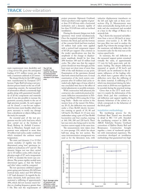
Fig 4. Average value<br />
of maximum rail<br />
deflection under<br />
locomotive axles at<br />
different speeds.<br />
project promoter Alptransit Gotthard,<br />
which specified a static rigidity of greater<br />
than 25·0 kN/mm with a horizontal<br />
inclination and a dynamic rigidity of<br />
less than 55·0 kN/mm with an inclined<br />
installation.<br />
During <strong>the</strong> dynamic fatigue test, both<br />
specimens were tested simultaneously.<br />
Once <strong>the</strong> required temperature of 40°C<br />
between <strong>the</strong> block pad and <strong>the</strong> bottom<br />
of <strong>the</strong> concrete block had been reached,<br />
10 million load cycles were applied<br />
with a vertical load component impact<br />
of 60 kN per support. One criterion in<br />
<strong>the</strong> tender specifications was that <strong>the</strong><br />
amplitude or <strong>the</strong> change in displacement<br />
amplitude should be less than<br />
20% between 100 and 10 million load<br />
cycles. The o<strong>the</strong>r was that <strong>the</strong> support<br />
points should not wear through, and <strong>the</strong><br />
boot must not show wear of more than<br />
50% of <strong>the</strong> wall thickness at any point.<br />
Examination of <strong>the</strong> specimens showed<br />
that both criteria had been met. A visual<br />
examination of <strong>the</strong> track system components<br />
after 10 million load cycles revealed<br />
only slight signs of wear, which it<br />
was concluded were due to <strong>the</strong> effect of<br />
initial adjustments or possible restraints.<br />
With construction well advanced, <strong>the</strong><br />
contractors also undertook practical dynamic<br />
deflection measurements in February<br />
and March 2014, using <strong>the</strong> 13 km<br />
long Faido – Bodio test section in <strong>the</strong><br />
western bore of <strong>the</strong> tunnel. On February<br />
20-21, <strong>the</strong> deflection was measured<br />
under a Class Re420 electric locomotive<br />
running at speeds of 10, 80 and<br />
120 km/h. On March 11-13 tests were<br />
undertaken using a pair of Class Re460<br />
locomotives and four coaches, running<br />
at 160, 180, 200 and 220 km/h. These<br />
last runs were also being used to test <strong>the</strong><br />
traction current supply at <strong>the</strong> same time.<br />
The measurements were taken close<br />
to cross-passage 150, which lies about<br />
half-way along <strong>the</strong> test section. The<br />
same instrumentation arrangement was<br />
used as for <strong>the</strong> laboratory tests, with<br />
Maximum rail deflection mm<br />
1∙6<br />
1∙4<br />
1∙2<br />
1∙0<br />
0∙8<br />
0∙6<br />
0∙4<br />
0∙2<br />
inductive displacement transducers on<br />
<strong>the</strong> left and right rails at three crosssections<br />
(Fig 2). Measurements were<br />
taken automatically during both sets of<br />
trials and also monitored and recorded<br />
at a base in <strong>the</strong> village of Biasca via a<br />
network link.<br />
Fig 3 shows <strong>the</strong> measured rail deflections<br />
from a test at 220 km/h at measurement<br />
cross-section 2. A 100 Hz<br />
low-pass filter was used to analyse <strong>the</strong><br />
signals. Fig 4 shows <strong>the</strong> average value of<br />
<strong>the</strong> maximum rail deflection under <strong>the</strong><br />
locomotive axles for <strong>the</strong> trial runs at <strong>the</strong><br />
various speed levels.<br />
In summary, <strong>the</strong> rail deflection at<br />
<strong>the</strong> measured support points remained<br />
virtually <strong>the</strong> same, at approximately<br />
1·3 mm for both quasi-static and dynamic<br />
loading. The deeper deflections<br />
measured at speeds of 80 km/h and<br />
120 km/h can be attributed to <strong>the</strong> dynamic<br />
influences of <strong>the</strong> loading vehicle,<br />
which have a greater effect on <strong>the</strong><br />
deflection curve than <strong>the</strong> stiffening of<br />
<strong>the</strong> elastic material. A stiffening of 1·3<br />
which was determined during <strong>the</strong> laboratory<br />
trials in 2010 was not significantly<br />
exceeded during <strong>the</strong> practical testing.<br />
Given that in <strong>the</strong> LVT track structure<br />
it is mainly <strong>the</strong> deformation of <strong>the</strong><br />
elastic block pad that contributes to<br />
rail deflection and support rigidity, <strong>the</strong><br />
dynamic behaviour of <strong>the</strong> system as a<br />
whole corresponds to <strong>the</strong> behaviour of<br />
<strong>the</strong> block pads 8 .<br />
Installation methodology<br />
The tracklaying process for <strong>the</strong><br />
Gotthard Base Tunnel was described<br />
in detail in RG 7.11 p44. Awarded<br />
<strong>the</strong> tracklaying contract in 2008, <strong>the</strong><br />
ARGE Fahrbahn Transtec Gotthard<br />
consortium of Balfour Beatty <strong>Rail</strong> and<br />
Renaissance Construction brought<br />
toge<strong>the</strong>r a team of trackwork specialists<br />
with international experience. The<br />
consortium developed an installation<br />
methodology that guaranteed very high<br />
0∙0<br />
0 50 100 150 200 250<br />
Speed km/h