


You also want an ePaper? Increase the reach of your titles
YUMPU automatically turns print PDFs into web optimized ePapers that Google loves.
Q<br />
Q7<br />
electrical connectors<br />
INFORMATION<br />
Inline Trailer Connectors<br />
12400, 12401, 12500, 12501<br />
Not supplied with wire, but the terminals are identified<br />
by numbers.<br />
7-Pole Connectors<br />
Accept wire up to 14AWG<br />
1. Left turn signal<br />
2. Accessory<br />
3. Ground<br />
4. Right turn signal<br />
5. Accessory<br />
6. Brake lights<br />
7. Rear, clearance and side marker lights<br />
12-Pole Connectors<br />
Pins 1-7 accept wire up to 14AWG, pins 8-12 up to 8AWG.<br />
1. Left turn signal<br />
2. Accessory<br />
3. Ground<br />
4. Right turn signal<br />
5. Accessory<br />
6. Brake lights<br />
7. Rear, clearance and side marker lights<br />
8. Accessory<br />
9. Accessory<br />
10. Ground<br />
11. Accessory<br />
12. Accessory<br />
13-Pole Connectors<br />
Pins 1-7 accept wire up to 14AWG, pins 8-13 up to 8AWG.<br />
Pins 1-7 as for 7-pole connector, pins 8-13 auxiliary.<br />
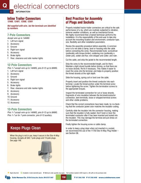
Keeps Plugs Clean<br />
When the plug is not in use, keep it secure in the Stor-A-Way<br />
housing. Accepts all SAE 7-pole plugs and 13-pole plugs.<br />
See page 148.<br />
Best Practice for Assembly<br />
of Plugs and Sockets<br />
Properly installed tractor-trailer connectors are critical to the safe<br />
performance of a rig, which are routinely subjected to vibration,<br />
extreme weather conditions, as well as mechanical forces.<br />
We highly recommend that a trained technician performs the<br />
installation. It is the responsibility of the end-user to take into<br />
account the mounting location and environment, conductor type,<br />
size, flexibility and other installation parameters.<br />
Review the assembly procedure before assembly. A common<br />
error is to not slide a clamp, boot or housing onto the cable<br />
before connecting the wires. Recommended tools: screwdriver<br />
(preferably with torque limiter); soldering iron (preferably a<br />
solder pot), solder and flux; wire stripper and cutter; and ruler.<br />
Cut the cable, and strip the jacket to the recommended length.<br />
Strip the wires to the recommended length, and tin them.<br />
Maintain a tight strand bundle before tinning, so that there are<br />
no loose strands. Re-tin if necessary. This makes it easier to<br />
insert the wires into the terminal, and helps to properly position<br />
the tinned strands at the right depth.<br />
Slide the housing, spring coil or boot over the cable.<br />
Properly insert and position the tinned conductor into each<br />
terminal. Locate the tinned portion under the terminal screw<br />
before tightening the screw. Tighten the termination screws to<br />
the appropriate torques.<br />
Inspect the terminated connection for cut or loose strands,<br />
fragments of wire insulation between the terminal/conductor<br />
connection, bent terminals, loose or stripped terminal screws<br />
and other visible problems.<br />
Check that the correct connections have been made, by re-checking<br />
that the conductor jacket color matches the insulator coding.<br />
Carefully slide the insulator into the connector housing, making<br />
sure that the insulator is fully seated. Don’t twist or lever the<br />
terminated conductor after it has been inserted and locked into<br />
the insulator. This may damage the terminal and put stress on<br />
the terminated connection.<br />
Finally tighten the housing screw or cable clamp.<br />
In order to keep a plug clean when not inserted in a socket,<br />
we recommend the use of the 11750 Stor-A-Way Plug Holder –<br />
see Section Q6.<br />
Rapid ship item. BP Available in retail clamshell pack. Minimum order quantity may apply. Part numbers needed in BOX require a -BX suffix on the purchase order.<br />
<strong>Cole</strong> <strong>Hersee</strong> Co. 20 Old Colony Ave, Boston, MA 02127-2467<br />
150<br />
T 617.268.2100 F 617.268.9490 www.colehersee.com


