


You also want an ePaper? Increase the reach of your titles
YUMPU automatically turns print PDFs into web optimized ePapers that Google loves.
<strong>Roller</strong> <strong>Bearings</strong><br />
l<br />
F <strong>Cylindrical</strong> <strong>Roller</strong> <strong>Bearings</strong><br />
7<br />
<strong>Cylindrical</strong> roller bearings with with opposed solid ribs on<br />
m<br />
h<br />
the inner <strong>and</strong> outer rings will support light to moderate<br />
F 3 c<br />
thrust loads.The maximum thrust load that a cylindrical<br />
B<br />
roller bearing will support is defined later in this section.<br />
F (F a ) 1<br />
5 b F2<br />
f<br />
d k F Field experience <strong>and</strong> laboratory tests have proven that<br />
6<br />
g F 4<br />
as long as as the the applied applied thrust thrust load load is less is than less the than applied the<br />
radial load <strong>and</strong> less than the limiting thrust rating, the<br />
A a<br />
(F a )<br />
applied radial load <strong>and</strong> less than the limiting thrust<br />
2<br />
rating,the fatigue life fatigue of the bearing life of the will bearing not be will adversely not be adversely affected.<br />
F 1 affected. Therefore, Therefore,the fatigue life fatigue of a cylindrical life of a cylindrical roller bearing roller<br />
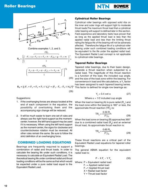
Combine examples 1, 2, <strong>and</strong> 3.<br />
bearing under such under combined such combined loading loading conditions conditions will will be<br />
V 6 4 4 4 4 4 4 4 44 V7<br />
AA<br />
be<br />
4 4 4 4 4 4 4 4 48<br />
equivalent equivalent to the to the life under life under the applied the applied radial radial load. load. The<br />
<br />
2<br />
The Equivalent Equivalent Radial Radial Load Load concept concept is not is not applicable applicable to<br />
2<br />
–F F1 – Fa g – F7<br />
m<br />
cylindrical roller bearings.<br />
1 a + F 3 c + F 5 h F a 2 g F<br />
2 7 m<br />
R<br />
<br />
<br />
<br />
l<br />
<br />
<br />
to cylindrical roller bearings.<br />
A =<br />
+<br />
l<br />
<br />
<strong>Tapered</strong> <strong>Roller</strong> <strong>Bearings</strong><br />
<br />
H<br />
H A<br />
1 2<br />
6 4 4 4 4 4 44 7 A<br />
4 4 4 4 4 4 48<br />
<strong>Tapered</strong> roller bearings, due to their basic design,<br />
2 ½<br />
F 2<br />
F2 2 b F<br />
b – F 4 d F<br />
4<br />
– F a <br />
a <br />
1 f + F<br />
f 6 k<br />
F6<br />
k<br />
generate a thrust reaction when subjected to a<br />
1<br />
<br />
<br />
<br />
radial load. The magnitude of this thrust reaction<br />
l<br />
(25)<br />
is a function of the load, the included cup angle,<br />
(25) <strong>and</strong> the size of the load zone within the bearing. For<br />
<br />
convenience in load <strong>and</strong> life calculations, a Y 2<br />
factor<br />
– F1 <br />
m 2<br />
has been assigned to each tapered bearing series.<br />
R <br />
B = [(-F 1 + F 3 + F 5 + F 7 V A ) 2 + (F 2 - F 4 - F 6 H A ) 2 ] ½<br />
This factor is defined for single row bearings as:<br />
2<br />
F2 – F4 – F6 m HA <br />
1 2<br />
(26)<br />
Y 2<br />
= 0.4 cot (27)<br />
Suggestions: SUGGESTIONS:<br />
Where = 1/2 included cup angle<br />
1. If the overhanging forces are always located at the<br />
end of each component in the equation, the<br />
possibility of overlooking them <strong>and</strong> the<br />
accompanying sign change will be reduced.<br />
2. It will be much easier to learn one set of rules <strong>and</strong><br />
always use the right h<strong>and</strong> support as the momentcenter;<br />
however, the left h<strong>and</strong> support may be used<br />
if it is necessary. When using the left h<strong>and</strong> support<br />
as the moment-center, the signs for clockwise <strong>and</strong><br />
counterclockwise rotation must be reversed. All<br />
other rules remain the same. Be sure to follow the<br />
strict definition of an overhanging force.<br />
COMBINED LOADING EQUATIONS<br />
<strong>Bearings</strong> are frequently required to support a<br />
combination of radial <strong>and</strong> thrust loads. In order to<br />
calculate the bearing life under such conditions, it is<br />
necessary to calculate an Equivalent Radial Load. The<br />
theoretical bearing life under combined radial <strong>and</strong> thrust<br />
loading conditions will be the same as that which would<br />
be expected under a pure radial load equal to the<br />
Equivalent Radial Load.<br />
When the load on bearing (A) is pure radial (R A<br />
) <strong>and</strong><br />
the load zone within the bearing is 180° or less, the<br />
approximate thrust reaction (TR A<br />
) is:<br />
TR A<br />
= 0.50 R A<br />
(Y 2<br />
) A<br />
(28)<br />
When the load zone on bearing (B) approaches 360°<br />
due to a combined radial load (R B<br />
) <strong>and</strong> an external<br />
thrust load, its approximate thrust reaction is:<br />
TR B<br />
= 0.60 R B<br />
(Y 2<br />
) B<br />
(29)<br />
These thrust reactions are a critical part of the<br />
Equivalent Radial Load equations for tapered roller<br />
bearings.<br />
The general ABMA equation for the equivalent<br />
radial load is:<br />
P = X F r<br />
+ Y F a<br />
(30)<br />
Where: P = Equivalent radial load<br />
F r = Applied radial load<br />
F a = Applied thrust load<br />
X = Radial load factor<br />
Y = Thrust load factor<br />
12


