

SKF - Spherical Plain Bearings and Rod Ends

Create successful ePaper yourself
Turn your PDF publications into a flip-book with our unique Google optimized e-Paper software.
Requisite bearing size<br />
To determine the requisite size of a spherical<br />
plain bearing or rod end, it is necessary to know<br />
the requisite rating life for the application. This<br />
depends on the type of machine, the operating<br />
conditions <strong>and</strong> the dem<strong>and</strong>s regarding operational<br />
reliability. The following steps can be<br />
used to determine requisite bearing size:<br />
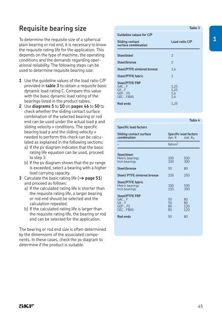
1 Use the guideline values of the load ratio C/P<br />
provided in table 3 to obtain a requisite basic<br />
dynamic load rating C. Compare this value<br />
with the basic dynamic load rating of the<br />
bearings listed in the product tables.<br />
2 Use diagrams 5 to 10 on pages 46 to 50 to<br />
check whether the sliding contact surface<br />
combination of the selected bearing or rod<br />
end can be used under the actual load p <strong>and</strong><br />
sliding velocity v conditions. The specific<br />
bearing load p <strong>and</strong> the sliding velocity v<br />
needed to perform this check can be calculated<br />
as explained in the following sections:<br />
a) If the pv diagram indicates that the basic<br />
rating life equation can be used, proceed<br />
to step 3.<br />
b) If the pv diagram shows that the pv range<br />
is exceeded, select a bearing with a higher<br />
load carrying capacity.<br />
3 Calculate the basic rating life († page 51)<br />
<strong>and</strong> proceed as follows:<br />
a) If the calculated rating life is shorter than<br />
the requisite rating life, a larger bearing<br />
or rod end should be selected <strong>and</strong> the<br />
calculation repeated.<br />
b) If the calculated rating life is larger than<br />
the requisite rating life, the bearing or rod<br />
end can be selected for the application.<br />
The bearing or rod end size is often determined<br />
by the dimensions of the associated components.<br />
In these cases, check the pv diagram to<br />
determine if the product is suitable.<br />
Guideline values for C/P<br />
Sliding contact<br />
surface combination<br />
Steel/steel 2<br />
Steel/bronze 2<br />
Steel/PTFE sintered bronze 1,6<br />
Steel/PTFE fabric 2<br />
Steel/PTFE FRP<br />
GAC .. F 1,25<br />
GX .. F 1,25<br />
GEP .. FS 1,6<br />
GEC .. FBAS 1,6<br />
<strong>Rod</strong> ends 1,25<br />
Load ratio C/P<br />
Table 3<br />
Table 4<br />
Specific load factors<br />
Sliding contact surface<br />
Specific load factors<br />
combination dyn. K stat. K 0<br />
– N/mm 2<br />
Steel/steel<br />
Metric bearings 100 500<br />
Inch bearings 100 300<br />
Steel/bronze 50 80<br />
Steel/ PTFE sintered bronze 100 250<br />
Steel/PTFE fabric<br />
Metric bearings 300 500<br />
Inch bearings 150 300<br />
Steel/PTFE FRP<br />
GAC .. F 50 80<br />
GX .. F 50 80<br />
GEP .. FS 80 120<br />
GEC .. FBAS 80 120<br />
<strong>Rod</strong> ends 50 80<br />
1<br />
45


