

SKF - Spherical Plain Bearings and Rod Ends

Create successful ePaper yourself
Turn your PDF publications into a flip-book with our unique Google optimized e-Paper software.
Design of bearing arrangements<br />
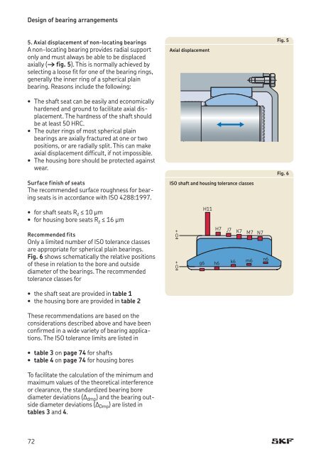
5. Axial displacement of non-locating bearings<br />
A non-locating bearing provides radial support<br />
only <strong>and</strong> must always be able to be displaced<br />
axially († fig. 5). This is normally achieved by<br />
selecting a loose fit for one of the bearing rings,<br />
generally the inner ring of a spherical plain<br />
bearing. Reasons include the following:<br />
• The shaft seat can be easily <strong>and</strong> economically<br />
hardened <strong>and</strong> ground to facilitate axial displacement.<br />
The hardness of the shaft should<br />
be at least 50 HRC.<br />
• The outer rings of most spherical plain<br />
bearings are axially fractured at one or two<br />
positions, or are radially split. This can make<br />
axial displacement difficult, if not impossible.<br />
• The housing bore should be protected against<br />
wear.<br />
Surface finish of seats<br />
The recommended surface roughness for bearing<br />
seats is in accordance with ISO 4288:1997.<br />
Axial displacement<br />
ISO shaft <strong>and</strong> housing tolerance classes<br />
Fig. 5<br />
Fig. 6<br />
• for shaft seats Rz ≤ 10 μm<br />
• for housing bore seats Rz ≤ 16 μm<br />
Recommended fits<br />
Only a limited number of ISO tolerance classes<br />
are appropriate for spherical plain bearings.<br />
Fig. 6 shows schematically the relative positions<br />
of these in relation to the bore <strong>and</strong> outside<br />
diameter of the bearings. The recommended<br />
tolerance classes for<br />
• the shaft seat are provided in table 1<br />
• the housing bore are provided in table 2<br />
These recommendations are based on the<br />
considerations described above <strong>and</strong> have been<br />
confirmed in a wide variety of bearing applications.<br />
The ISO tolerance limits are listed in<br />
• table 3 on page 74 for shafts<br />
• table 4 on page 74 for housing bores<br />
To facilitate the calculation of the minimum <strong>and</strong><br />
maximum values of the theoretical interference<br />
or clearance, the st<strong>and</strong>ardized bearing bore<br />
diameter deviations (Δ dmp ) <strong>and</strong> the bearing outside<br />
diameter deviations (Δ Dmp ) are listed in<br />
tables 3 <strong>and</strong> 4.<br />
+<br />
0<br />
+<br />
0<br />
H11<br />
H7 J7 K7 M7 N7<br />
g6 h6 k6 m6 n6<br />
72


