


Create successful ePaper yourself
Turn your PDF publications into a flip-book with our unique Google optimized e-Paper software.
<strong>SNT</strong> SPLIT PLUMMER BLOCKS<br />
Engineering • Mounting, Fitting, Setting and Installation<br />
EXAMPLE #1 –<br />
Calculating RIC Reduction Using a Spherical Roller Bearing with Tapered Bore<br />
Given bearing number 22328K C3 (140 mm bore with C3 clearance)<br />
is to be mounted on a tapered shaft. Using a set of feeler gages,<br />
RIC is measured at (see fig. E-3):<br />
RIC = 0.178 mm<br />
Suggested reduction of RIC due to installation =<br />
0.064 mm – 0.089 mm, found in table E-5 on page E-10.<br />
Calculate the clearance after mounting (see fig. E-4):<br />
0.178 mm – 0.076 mm = 0.102 mm<br />
For this example, the value of 0.076 mm was obtained by taking the mid-range value of<br />
the upper and lower limits found in the tables on page E-10.<br />
Therefore, the locknut should be tightened until ric reaches<br />
0.102 mm.<br />
It also should be noted that the value obtained by reading the<br />
suggested ric after installation directly from the table is 0.056 mm.<br />
Observations:<br />
• Bearing 22230EM, nominal 150 mm bore and 270 mm O.D.,<br />
standard class, operating at 1200 RPM.<br />
• Float bearing position so the stationary O.D. should be free<br />
to move in <strong>SNT</strong> housing, with the locating ring removed.<br />
• With shaft/inner ring rotation and the moderate loading<br />
0.09C, the bore should be tight fit.<br />
We can use the nominal fit charts in table E-6 on page E-15 (shaft<br />
fit) to help guide our ISO fit selection.<br />
Shaft Fit at 150 mm Bore: ISO p6<br />
From the shaft fit chart at 150 mm nominal bore at p6 (table E-8,<br />
page E-20), the shaft tolerance is nominal +0.043 to +0.068 mm.<br />
Therefore we have the following bore range:<br />
max. shaft = 150.068 mm<br />
min. shaft = 150.043 mm<br />
This yields a shaft fit:<br />
max. fit = max. shaft - min. bore<br />
= 150.068 - 149.075<br />
= 0.093 mm tight<br />
min. fit = min. shaft - max. bore<br />
= 150.043 - 150.000<br />
= 0.043 mm tight<br />
For the primary selection of RIC, the major parameters are the<br />
bearing speed and the fits. For our example, we know that the<br />
shaft fit is 0.043 mm tight to 0.093 mm tight. We know the housing<br />
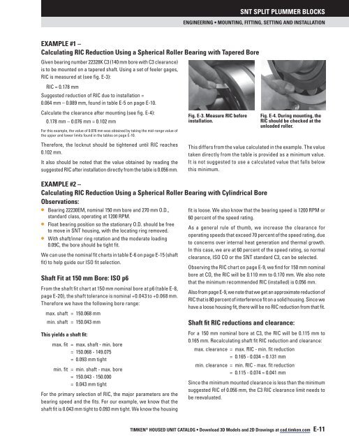
Fig. E-3. Measure RIC before<br />
installation.<br />
Fig. E-4. During mounting, the<br />
RIC should be checked at the<br />
unloaded roller.<br />
This differs from the value calculated in the example. The value<br />
taken directly from the table is provided as a minimum value.<br />
It is not suggested to use a calculated value that falls below<br />
this minimum.<br />
EXAMPLE #2 –<br />
Calculating RIC Reduction Using a Spherical Roller Bearing with Cylindrical Bore<br />
fit is loose. We also know that the bearing speed is 1200 RPM or<br />
60 percent of the speed rating.<br />
As a general rule of thumb, we increase the clearance for<br />
operating speeds that exceed 70 percent of the speed rating, due<br />
to concerns over internal heat generation and thermal growth.<br />
In this case, we are at 60 percent of the speed rating, so normal<br />
clearance, ISO CO or the <strong>SNT</strong> standard C3, can be selected.<br />
Observing the RIC chart on page E-9, we find for 150 mm nominal<br />
bore at CO, the RIC will be 0.110 mm to 0.170 mm. We also note<br />
that the minimum recommended RIC (installed) is 0.056 mm.<br />
Also from page E-9, we note that we get an approximate reduction of<br />
ric that is 80 percent of interference fit on a solid housing. Since we<br />
have a loose housing fit, there will be no ric reduction from that fit.<br />
Shaft fit RIC reductions and clearance:<br />
For a 150 mm nominal bore at C3, the RIC will be 0.115 mm to<br />
0.165 mm. Recalculating shaft fit RIC reduction and clearance:<br />
max. clearance = max. RIC - min. fit reduction<br />
= 0.165 - 0.034 = 0.131 mm<br />
min. clearance = min. RIC - max. fit reduction<br />
= 0.115 - 0.074 = 0.041 mm<br />
Since the minimum mounted clearance is less than the minimum<br />
suggested RIC of 0.056 mm, the C3 RIC clearance limit needs to<br />
be reevaluated.<br />
TIMKEN ® HOUSED UNIT CataloG • Download 3D Models and 2D Drawings at cad.timken.com E-11


