


You also want an ePaper? Increase the reach of your titles
YUMPU automatically turns print PDFs into web optimized ePapers that Google loves.
<strong>SNT</strong> SPLIT PLUMMER BLOCKS<br />
INSTALLATION GUIDES • MOUNTING HOUSINGS WITH LABYRINTH SEALS<br />
MOUNTING HOUSINGS WITH LABYRINTH SEALS<br />
Prior to starting installation, please read the following instructions.<br />
Contact a <strong>Timken</strong> engineer with any questions.<br />
1. Clean the work area. Check the dimensional and form<br />
accuracy of the shaft seat. Note: The shaft roundness<br />
specification should be half of the O.D. tolerance. Ensure<br />
the shaft is free from burrs, gouges or other imperfections.<br />
2. Ensure the surface roughness of the support surface<br />
Ra ≤ 12.5 μm. Ensure flatness is within 0.08 mm (base) and<br />
0.125 mm aggregate (housing base and mounting surface).<br />
3. For bearings on adapter sleeves, determine the position<br />
of the housing relative to the adapter sleeve on the shaft.<br />
For bearings that have to be relubricated from the side, the<br />
grease fitting in the housing cap should always face away<br />
from the locknut on the adapter sleeve. Grease should<br />
be supplied at the end cover side where housings are<br />
mounted on the end of a shaft. Be sure to position the base<br />
correctly since the cap only fits in one direction.<br />
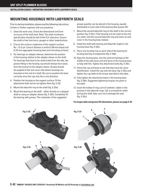
4. Position the housing on the support surface. Fit the<br />
attachment bolts but do not tighten them (fig. E-22).<br />
5. Mount the labyrinth ring on the shaft (fig. E-23a).<br />
6. Mount the bearing on the shaft – either directly on a stepped<br />
shaft or using an adapter sleeve (fig. E-23b). Completely fill<br />
the bearing with grease. The remainder of the suggested<br />
grease quantity can be placed in the housing, equally<br />
distributed on each side of the bearing (See grease fill).<br />
7. Mount the second labyrinth ring on the shaft in the correct<br />
position (fig. E-23c). If the housing is to be used on the end<br />
of a shaft, omit the second labyrinth ring and insert an end<br />
cover in the housing base instead.<br />
8. Install the shaft with bearing and labyrinth ring(s) in the<br />
housing base (fig. E-24a).<br />
9. Place one locating ring on each side of the bearing for<br />
locating bearing arrangements (fig. E-24b).<br />
10. Align the housing base. Use the vertical markings at the<br />
middle of the side faces and end faces of the housing base<br />
to help with this. Tighten the attachment bolts (fig. E-24c).<br />
11. Check the cap and base to see that they have the same<br />
identification. Install the cap onto the base (fig. E-25a) and<br />
tighten the cap bolts to the torque specified in the table.<br />
12. Fully tighten the attachment bolts in the housing base<br />
(fig. E-25b). Suggested tightening torques are given in<br />
the table.<br />
13. Insert the hollow O-ring cord of synthetic rubber in the<br />
grooves in the labyrinth rings. Use a screwdriver while<br />
turning the shaft, take care not to damage the seal<br />
(fig. E-25c).<br />
For torque table and grease fill information, please see page E-45.<br />
Fig. E-22 Fig. E-23<br />
b<br />
a<br />
c<br />
Fig. E-24<br />
b<br />
a<br />
Fig. E-25<br />
a<br />
c<br />
b<br />
c<br />
E-42 TIMKEN ® HOUSED UNIT CataloG • Download 3D Models and 2D Drawings at cad.timken.com


