SPLIT SYSTEM AIR CONDITIONER TECHNICAL & SERVICE ...
SPLIT SYSTEM AIR CONDITIONER TECHNICAL & SERVICE ...
SPLIT SYSTEM AIR CONDITIONER TECHNICAL & SERVICE ...

Create successful ePaper yourself
Turn your PDF publications into a flip-book with our unique Google optimized e-Paper software.
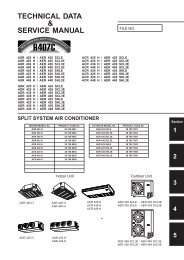
<strong>TECHNICAL</strong> & <strong>SERVICE</strong> MANUAL<br />
ADR518CW AE518SC<br />
AE518SC3 / AER518SCL3<br />
ADR518HW AE518SH<br />
AE518SH3 / AER518SH3<br />
INDOOR UNIT<br />
<strong>SPLIT</strong> <strong>SYSTEM</strong> <strong>AIR</strong> <strong>CONDITIONER</strong><br />
0.8180.224.0<br />
OUTDOOR UNIT<br />
®<br />
OCTOBER 01
A<br />
B<br />
C<br />
D<br />
E<br />
F<br />
G<br />
H<br />
I<br />
L<br />
M<br />
N<br />
O<br />
P<br />
Q<br />
R<br />
H<br />
TABLE OF CONTENTS<br />
SPECIFICATIONS...........................................................................................................PAGE...3<br />
MAJOR COMPONENT SPECIFICATION.....................................................................................9<br />
OTHERS COMPONENT SPECIFICATIONS................................................................................16<br />
OPERATING RANGE....................................................................................................................21<br />
DIMENSIONALE DATA.................................................................................................................22<br />
FUNCTION.....................................................................................................................................24<br />
REFRIGERANT FLOW DIAGRAM................................................................................................31<br />
ELECTRIC WIRING DIAGRAM.....................................................................................................32<br />
TROUBLESHOOTING COOLING MODEL...................................................................................36<br />
SAME PARTS OF <strong>AIR</strong> <strong>CONDITIONER</strong> DO NOT OPERATE........................................................43<br />
<strong>AIR</strong> <strong>CONDITIONER</strong> OPERATES,BUT ABNORMALITIES OCCUR.............................................44<br />
TROUBLESHOOTING HEATING MODEL....................................................................................45<br />
SAME PARTS OF <strong>AIR</strong> <strong>CONDITIONER</strong> DO NOT OPERATE.......................................................52<br />
<strong>AIR</strong> <strong>CONDITIONER</strong> OPERATES,BUT ABNORMALITIES OCCUR............................................55<br />
IS SENSOR IS DEFECTIVE..........................................................................................................56<br />
CHECKING ELECTRICAL ...........................................................................................................59
A SPECIFICATIONS<br />
1)UNIT SPECIFICATIONS<br />
UNIT MODEL<br />
Power source 220 / 230 / 240V - 1 - 50 Hz<br />
Shipping volume m 3 0,33 0,3<br />
Shipping weight (approx.) kg 44 57<br />
NOTA. Rating conditions:<br />
INDOOR UNIT<br />
OUTDOOR UNIT<br />
W (Kcal/h) 4.950 (4,250)<br />
Cooling: Outside air temp.: 35°C DB, indoor unit entering air temp.: 27°C DB / 19°C WB<br />
3<br />
ADR518CW<br />
AE518SC<br />
PERFORMANCES COOLING<br />
Capacity<br />
BTU/h 16,900<br />
Air circulation (high - med - low) m 3 /h 780<br />
External static pressure (high speed) mm w.g. (Pa) 5 (49) at shipment - 10 (98) using the Booster cable<br />
Moisture removal (high speed) l/h 2,8<br />
Umidità ELECTRICAL asportata RATINGS (alta velocità) l/h 0,9<br />
Voltage rating V 230<br />
Available voltage range V 198 ÷ 264<br />
Running ampere A 9.5<br />
Power input W 2,06<br />
Power factor % 94<br />
Compressor locked rotor amperes A 46<br />
C.O.P.<br />
FEATURES<br />
W/W 2.4<br />
Controls Microprocessor<br />
Control unit Remote control<br />
Temperature control I.C. thermostat<br />
Timer ON/OFF 12 hours<br />
Fan speed indoor / outdoor 3 + auto / 2 auto<br />
Air filter Washable, easy access (accessory)<br />
Compressor Rotary (hermetic)<br />
Refrigerant / ref. control / amount charged at ship g R22 / capillary tube / 1.710 g<br />
Operation sound<br />
Indoor Hi / Me / Lo (1 m) dB-A<br />
Outdoor Hi / Lo (3 m) dB-A<br />
42 / 37 / 32<br />
51 / 44<br />
Max. tubing length m (with factory R22 charge) 10<br />
Max. allowable tubing length m ....(with.R22.addition)....................20<br />
Required amount of additional refrigerant g/m 25<br />
Limit of elevation difference<br />
m<br />
between the two units 7<br />
Refrigerant tube<br />
diameter<br />
Narrow tube mm (in.)<br />
Wide tube mm (in.)<br />
6.35 (1/4”)<br />
12.7 (1/2”)<br />
Accessory Booster cable<br />
DIMENSIONS AND WEIGTH INDOOR UNIT OUTDOOR UNIT<br />
Higth mm 316 630<br />
Width mm 750 830<br />
Depth mm 665 305<br />
Net weigth kg 42 52<br />
Data subject to change without notice.
UNIT MODEL<br />
Power source 400V - 3N - 50 Hz (4 wires)<br />
Shipping volume m 3 0,33 0,3<br />
Shipping weight (approx.) kg 44 57<br />
NOTA. Rating conditions:<br />
INDOOR UNIT<br />
OUTDOOR UNIT<br />
W (Kcal/h) 4.950 (4250)<br />
Cooling: Outside air temp.: 35°C DB, indoor unit entering air temp.: 27°C DB / 19°C WB<br />
4<br />
ADR518CW<br />
AE518SC3<br />
PERFORMANCES COOLING<br />
Capacity<br />
BTU/h 16,900<br />
Air circulation (high - med - low) m 3 /h 780<br />
External static pressure (high speed) mm w.g. (Pa) 5 (49) at shipment - 10 (98) using the Booster cable<br />
Moisture removal (high speed) l/h 2,8<br />
Umidità ELECTRICAL asportata RATINGS (alta velocità) l/h 0,9<br />
Voltage rating V 400<br />
Available voltage range V 342 ÷ 440<br />
Running ampere A 4.0<br />
Power input W 1.96<br />
Power factor % 84<br />
Compressor locked rotor amperes A 21.5<br />
C.O.P.<br />
FEATURES<br />
W/W 2.5<br />
Controls Microprocessor<br />
Control unit Remote control<br />
Temperature control I.C. thermostat<br />
Timer ON/OFF 12 hours<br />
Fan speed indoor / outdoor 3 + auto / 2 auto<br />
Air filter Washable, easy access (accessory)<br />
Compressor Rotary (hermetic)<br />
Refrigerant / ref. control / amount charged at ship g R22 / capillary tube / 1.405 g<br />
Operation sound<br />
Indoor Hi / Me / Lo (1 m) dB-A<br />
Outdoor Hi / Lo (3 m) dB-A<br />
42 / 37 / 32<br />
51 / 44<br />
Max. tubing length m (with factory R22 charge) 10<br />
Max. allowable tubing length m ....(with.R22.addition).....................20<br />
Required amount of additional refrigerant g/m 25<br />
Limit of elevation difference<br />
between the two units<br />
Refrigerant tube<br />
diameter<br />
m<br />
Narrow tube mm (in.)<br />
Wide tube mm (in.)<br />
6,35 (1/4”)<br />
12,7 (1/2”)<br />
Accessory Booster cable<br />
DIMENSIONS AND WEIGTH INDOOR UNIT OUTDOOR UNIT<br />
Higth mm 316 630<br />
Width mm 750 830<br />
Depth mm 665 305<br />
Net weigth kg 42 52<br />
7<br />
Data subject to change without notice.
UNIT MODEL<br />
Power source 400V - 3N - 50 Hz (4 wires)<br />
Shipping volume m 3 0.33 0.3<br />
Shipping weight (approx.) kg 44 57<br />
NOTA. Rating conditions:<br />
INDOOR UNIT<br />
OUTDOOR UNIT<br />
W (Kcal/h) 5900 (5070)<br />
Cooling: Outside air temp.: 35°C DB, indoor unit entering air temp.: 27°C DB / 19°C WB<br />
5<br />
ADR518CW<br />
AER518SCL3<br />
PERFORMANCES COOLING<br />
Capacity<br />
BTU/h 17.400<br />
Air circulation (high - med - low) m 3 /h 780<br />
External static pressure (high speed) mm w.g. (Pa) 5 (49 at shipment - 10 (98) using the Booster cable<br />
Moisture removal (high speed) l/h 2.8<br />
Umidità ELECTRICAL asportata RATINGS (alta velocità) l/h 0,9<br />
Voltage rating V 400<br />
Available voltage range V 342 : 440<br />
Running ampere A 3.6<br />
Power input W 2.000<br />
Power factor % 80<br />
Compressor locked rotor amperes A 21.5<br />
C.O.P.<br />
FEATURES<br />
W/W 2,3<br />
Controls Microprocessor<br />
Control unit Remote control<br />
Temperature control I.C. thermostat<br />
Timer ON/OFF 12 hours<br />
Fan speed indoor / outdoor 3 + auto / 2 auto<br />
Air filter Washable, easy access (accessory)<br />
Compressor Rotary (hermetic)<br />
Refrigerant / ref. control / amount charged at ship g R407C / capillary tube / 1.710 g<br />
Operation sound<br />
Indoor Hi / Me / Lo (1 m) dB-A<br />
Outdoor Hi / Lo (3 m) dB-A<br />
42 / 37 / 32<br />
51/ 44<br />
Max. tubing length m (with factory R407C charge) 10<br />
Max. allowable tubing length m (with R407C addition) 30<br />
Required amount of additional refrigerant g/m 25<br />
Limit of elevation difference<br />
between the two units<br />
Refrigerant tube<br />
diameter<br />
m<br />
Narrow tube mm (in.)<br />
Wide tube mm (in.)<br />
6,35 (1/4”)<br />
12.7(1/2")<br />
Accessory Booster cable<br />
DIMENSIONS AND WEIGTH INDOOR UNIT OUTDOOR UNIT<br />
Higth mm 316 630<br />
Width mm 750 830<br />
Depth mm 665 305<br />
Net weigth kg 42 52<br />
7<br />
Data subject to change without notice.
UNIT MODEL<br />
Power source 220 / 230 / 240V - 1 - 50 Hz<br />
Shipping volume m 3 0,33 0.3<br />
Shipping weight (approx.) kg 44 57<br />
NOTA. Rating conditions:<br />
INDOOR UNIT<br />
OUTDOOR UNIT<br />
W (Kcal/h) 4.950 (4.257) 6000(5160)<br />
6<br />
ADR518HW<br />
AE518SH<br />
PERFORMANCES COOLING HEATING<br />
Capacity<br />
BTU/h 16.900 20500<br />
Air circulation (high - med - low) m 3 /h 750<br />
External static pressure (high speed) mm w.g. (Pa) 5 (49) at shipment - 10 (98) using the Booster cable<br />
Moisture removal (high speed) l/h 2.8 ---<br />
Umidità ELECTRICAL asportata RATINGS (alta velocità) l/h 0,9<br />
Voltage rating V 230<br />
Available voltage range V 198 ÷ 264<br />
Running ampere A 9.8 10.3<br />
Power input W 2.100 2.150<br />
Power factor % 93 90<br />
Compressor locked rotor amperes A 57<br />
C.O.P. W/W 2.35 2.8<br />
FEATURES<br />
Controls Microprocessor<br />
Control unit Remote control<br />
Temperature control I.C. thermostat<br />
Timer ON/OFF 12 hours<br />
Fan speed indoor / outdoor 3 + auto / 2 auto<br />
Air filter Washable, easy access (accessory)<br />
Compressor Rotary (hermetic)<br />
Refrigerant / ref. control / amount charged at ship g R22 / capillary tube / 1.87 g<br />
Operation sound<br />
Indoor Hi / Me / Lo (1 m) dB-A<br />
Outdoor Hi / Lo (3 m) dB-A<br />
42 / 37 / 32<br />
51 / 44<br />
Max. tubing length m (standard refrigerant charge) 10<br />
Max. allowable tubing length m ....(with.R22.addition).....................30<br />
Required amount of additional refrigerant g/m 25<br />
Limit of elevation difference<br />
between the two units<br />
Refrigerant tube<br />
diameter<br />
m<br />
Narrow tube mm (in.)<br />
Wide tube mm (in.)<br />
6,35 (1/4”)<br />
12.7 (1/2”)<br />
Accessory Booster cable<br />
DIMENSIONS AND WEIGTH INDOOR UNIT OUTDOOR UNIT<br />
Higth mm 316 630<br />
Width mm 750 830<br />
Depth mm 665 305<br />
Net weigth kg 42 52<br />
Data subject to change without notice.<br />
Cooling: Outside air temp.: 35°C DB, indoor unit entering air temp.: 27°C DB / 19°C WB<br />
7
UNIT MODEL<br />
Power source 400V - 3N - 50 Hz (4 wires)<br />
Shipping volume m 3 0,33 0.3<br />
Shipping weight (approx.) kg 44 57<br />
NOTA. Rating conditions:<br />
INDOOR UNIT<br />
OUTDOOR UNIT<br />
W (Kcal/h) 4.700 (4.042) 5.800(6.744)<br />
7<br />
ADR518HW<br />
AE518SH3<br />
PERFORMANCES COOLING HEATING<br />
Capacity<br />
BTU/h 16.100 19.800<br />
Air circulation (high - med - low) m 3 /h 750<br />
External static pressure (high speed) mm w.g. (Pa) 5 (49) at shipment - 10 (98) using the Booster cable<br />
Moisture removal (high speed) l/h 2.8 ---<br />
Umidità ELECTRICAL asportata RATINGS (alta velocità) l/h 0,9<br />
Voltage rating V 400<br />
Available voltage range V 342 ÷ 440<br />
Running ampere A 3.8 4.0<br />
Power input W 2.000 2.100<br />
Power factor % 93 90<br />
Compressor locked rotor amperes A 22<br />
C.O.P. W/W 2.35 2.76<br />
FEATURES<br />
Controls Microprocessor<br />
Control unit Remote control<br />
Temperature control I.C. thermostat<br />
Timer ON/OFF 12 hours<br />
Fan speed indoor / outdoor 3 + auto / 2 auto<br />
Air filter Washable, easy access (accessory)<br />
Compressor Rotary (hermetic)<br />
Refrigerant / ref. control / amount charged at ship g R22 / capillary tube / 2.450g<br />
Operation sound<br />
Indoor Hi / Me / Lo (1 m) dB-A<br />
Outdoor Hi / Lo (3 m) dB-A<br />
42 / 37 / 32<br />
51 / 44<br />
Max. tubing length m (standard refrigerant charge) 10<br />
Max. allowable tubing length m ....(with.R22.addition).....................30<br />
Required amount of additional refrigerant g/m 25<br />
Limit of elevation difference<br />
between the two units<br />
Refrigerant tube<br />
diameter<br />
m<br />
Narrow tube mm (in.)<br />
Wide tube mm (in.)<br />
6,35 (1/4”)<br />
12.7 (1/2”)<br />
Accessory Booster cable<br />
DIMENSIONS AND WEIGTH INDOOR UNIT OUTDOOR UNIT<br />
Higth mm 316 630<br />
Width mm 750 830<br />
Depth mm 665 305<br />
Net weigth kg 42 52<br />
Data subject to change without notice.<br />
Cooling: Outside air temp.: 35°C DB, indoor unit entering air temp.: 27°C DB / 19°C WB<br />
7
UNIT MODEL<br />
Power source 400V - 3N - 50 Hz (4 wires)<br />
Shipping volume m 3 0,33 0.3<br />
Shipping weight (approx.) kg 44 57<br />
NOTA. Rating conditions:<br />
INDOOR UNIT<br />
OUTDOOR UNIT<br />
W (Kcal/h) 4.800 (4.128) 6300(5418)<br />
8<br />
ADR518HW<br />
AER518SH3<br />
PERFORMANCES COOLING HEATING<br />
Capacity<br />
BTU/h 16.400 21.500<br />
Air circulation (high - med - low) m 3 /h 750<br />
External static pressure (high speed) mm w.g. (Pa) 5 (49) at shipment - 10 (98) using the Booster cable<br />
Moisture removal (high speed) l/h 2.8 ---<br />
Umidità ELECTRICAL asportata RATINGS (alta velocità) l/h 0,9<br />
Voltage rating V 400<br />
Available voltage range V 342 ÷ 440<br />
Running ampere A 4.0 4.2<br />
Power input W 2.150 2.250<br />
Power factor % 93 90<br />
Compressor locked rotor amperes A 22<br />
C.O.P. W/W 2.23 2.8<br />
FEATURES<br />
Controls Microprocessor<br />
Control unit Remote control<br />
Temperature control I.C. thermostat<br />
Timer ON/OFF 12 hours<br />
Fan speed indoor / outdoor 3 + auto / 2 auto<br />
Air filter Washable, easy access (accessory)<br />
Compressor Rotary (hermetic)<br />
Refrigerant / ref. control / amount charged at ship g R407C / capillary tube / 1.600 g<br />
Operation sound<br />
Indoor Hi / Me / Lo (1 m) dB-A<br />
Outdoor Hi / Lo (3 m) dB-A<br />
42 / 37 / 32<br />
51 / 44<br />
Max. tubing length m (standard refrigerant charge) 10<br />
Max. allowable tubing length m ....(with.R407C.addition)................30<br />
Required amount of additional refrigerant g/m 25<br />
Limit of elevation difference<br />
between the two units<br />
Refrigerant tube<br />
diameter<br />
m<br />
Narrow tube mm (in.)<br />
Wide tube mm (in.)<br />
6,35 (1/4”)<br />
12.7 (1/2”)<br />
Accessory Booster cable<br />
DIMENSIONS AND WEIGTH INDOOR UNIT OUTDOOR UNIT<br />
Higth mm 316 630<br />
Width mm 750 830<br />
Depth mm 665 305<br />
Net weigth kg 42 52<br />
Data subject to change without notice.<br />
Cooling: Outside air temp.: 35°C DB, indoor unit entering air temp.: 27°C DB / 19°C WB<br />
7
B MAJOR COMPONENT SPECIFICATIONS<br />
INDOOR UNIT<br />
UNIT MODEL ADR518CW / ADR518HW<br />
Power source 220 / 230 / 240V -1 - 50 Hz<br />
REMOTE CONTROL UNIT RCS-U251G<br />
CONTROLLER P.C.B. POW-U186GH<br />
Controls Microprocessor<br />
Control circuit fuse 250V - 3A<br />
FAN Centrifugal<br />
Number ... dia. / length mm 2 ... Ø 200 / L 230<br />
FAN MOTOR<br />
Model ... Number K48410M01526 ... 1<br />
Power source V 220 / 230 / 240-1-50 Hz<br />
No. di poli ... giri/min (230V-max) 4 ... 1040<br />
Nominal output W 70<br />
Coil resistance<br />
(Ambient temp. 20°C)<br />
SAFETY DEVICES Internal type<br />
Operating temp.<br />
Open<br />
Close<br />
°C<br />
°C<br />
130 ± 18<br />
179 ± 15<br />
Run capacitor<br />
Rated<br />
µF 5<br />
VAC 440<br />
Voltage AC 230V - 50 Hz<br />
Input 114.7 W<br />
Coil Aluminum plate fin / Copper tube<br />
Fin pitch mm 1,8<br />
Fase area m 2 0,125<br />
EXTERNAL FINISH<br />
Ω WHT - BRN :181,1<br />
9<br />
ORG - VLT :136,8<br />
YEL - ORG :151,4<br />
BLK - YEL :120,6<br />
WHT - VLT :112,7<br />
VLT - PNK :144,2<br />
DRAIN PUMP<br />
Model PC<br />
Total head capacity 0.4 m / 0.6 l/m<br />
HEAT EXCHANGER<br />
Rows 3<br />
Insulated galvanized metal sheet
Outdoor Unit AE518SC3<br />
Controller<br />
PCB<br />
Part No. POW-C181BL<br />
Control circuit fuse 250V – 5A<br />
Type Rotary (Hermetic)<br />
Compressor model C-2R173H8V- 80817C88D<br />
Source 380 – 400 V – 3N ~ 50 Hz<br />
Nominal output W 1,700<br />
Compressor oil ... Amount cc SUNISO 4GSD-T ... 800<br />
Coil resistance (Ambient temp. 25°C) Ω C – R : 6.369<br />
C – S : 6.073<br />
R – S : 6.217<br />
Type Internal protector External protector<br />
Safety<br />
devices<br />
Overload relay<br />
Operating temp.<br />
Open<br />
Close<br />
°C<br />
°C<br />
—<br />
125 ± 5<br />
Automatic reclosing<br />
HOE-10TB TH-5A<br />
—<br />
—<br />
Operating amp.(Ambient temp. 25°C) — 5A<br />
Run capacitor<br />
µF<br />
VAC<br />
—<br />
—<br />
Crank case heater 240V 30W<br />
Type Propeller<br />
Q´ty ... Dia. mm 1 ... ø400<br />
Fan motor model ... Q´ty SMEN 19 TFB6055 ... 1<br />
Source 220 – 230 V ~ 50 Hz<br />
No. of poles ... rpm (220 V, High) 6 ... 910<br />
Nominal output W 43<br />
Coil resistance (Ambient temp. 20°C) Ω WHT – BRN : 77.7 WHT - YEL : 366<br />
WHT – PNK : 211<br />
Safety<br />
devices<br />
Type<br />
Operating temp.<br />
Open<br />
Close<br />
°C<br />
Internal type<br />
130 ± 5<br />
Automatic reclosing<br />
Run capacitor<br />
µF<br />
VAC<br />
2.0<br />
400<br />
Coil Aluminum plate fin / Copper tube<br />
Rows 2<br />
Fin pitch mm 1.8<br />
Face area m 2<br />
0.508<br />
External Finish Acrylic baked-on enamel finish<br />
Compressor<br />
Fan & Fan Motor<br />
Heat<br />
Exch. Coil<br />
10<br />
DATA SUBJECT TO CHANGE WITHOUT NOTICE.
Outdoor Unit AE518SC<br />
Controller PCB —<br />
Compressor<br />
Type Rotary (Hermetic)<br />
Compressor model PH36VTRT<br />
Nominal output W 1,600<br />
Compressor oil ... Amount cc DIAMOND... 900<br />
Coil resistance (Ambient temp. 20°C) Ω C – R : 1.06<br />
11<br />
C – S : 2.03<br />
Type Internal protector (OLR)<br />
Safety Overload relay —<br />
devices Operating temp. Open °C Automatic opening 155 ± 5<br />
Close °C Automatic reclosing 90 ± 10<br />
Operating amp. (Ambient temp. 25 C) Trip in 3 to 10 sec at 54A<br />
Run capacitor µF 55.0<br />
VAC 450<br />
Crank case heater —<br />
Type Propeller<br />
Number ... Dia. mm 1 ... ø 400<br />
Fan motor model ... Number Smen 19TFB6055 ... 1<br />
No. of poles ... rpm (230 V, High) 6 ... 910<br />
Nominal output W 43<br />
Coil resistance (Ambient temp. 20°C) Ω WHT – BRN : 77.7 ± 7%<br />
WHT – YEL : 366.0 ± 7%<br />
WHT – PNK : 211.0 ± 7%<br />
Safety Type Thermal protector<br />
devices Operating temp. Open °C 130 ± 5<br />
Close Automatic reclosing<br />
Run capacitor µF 2.0<br />
VAC 440<br />
Coil Aluminum plate fin / Copper tube<br />
Rows 2<br />
Fin pitch mm 1.8<br />
Face area m2 0.508<br />
External Finish Acrylic baked-on enamel finish<br />
Fan & Fan Motor<br />
Heat<br />
Exch. Coil<br />
DATA SUBJECT TO CHANGE WITHOUT NOTICE.
Outdoor Unit AER518SCL3<br />
Controller<br />
PCB<br />
Part No. POW-C181BL<br />
Control circuit fuse 250V – 5A<br />
Type Rotary (Hermetic)<br />
Compressor model C-2RN173H8W 80807088<br />
Source 380 – 400 V – 3N ~ 50 Hz<br />
Nominal output W 1,700<br />
Compressor oil ... Amount cc FV68S ... 800<br />
Coil resistance (Ambient temp. 25°C) Ω C – R : 6.369<br />
C – S : 6.073<br />
R – S : 6.217<br />
Type Internal protector External protector<br />
Safety<br />
devices<br />
Overload relay<br />
Operating temp.<br />
Open<br />
Close<br />
°C<br />
°C<br />
—<br />
Automatic opening<br />
Automatic reclosing<br />
HOE-10TB TH-5A<br />
—<br />
—<br />
Operating amp.(Ambient temp. 25°C) — 5A<br />
Run capacitor<br />
µF<br />
VAC<br />
—<br />
—<br />
Crank case heater 240V 30W<br />
Type Propeller<br />
Q´ty ... Dia. mm 1 ... ø400<br />
Fan motor model ... Q´ty SMEN 19 TFB6047 ... 1<br />
Source 220 – 230 V ~ 50 Hz<br />
No. of poles ... rpm (220 V, High) 6 ... 910<br />
Nominal output W 43<br />
Coil resistance (Ambient temp. 20°C) Ω WHT – BRN : 83.4<br />
WHT – PNK : 218.7<br />
Safety<br />
devices<br />
Type<br />
Operating temp.<br />
Open<br />
Close<br />
°C<br />
Internal type<br />
130 ± 5<br />
Automatic reclosing<br />
Run capacitor<br />
µF<br />
VAC<br />
2.0<br />
440<br />
Coil Aluminum plate fin / Copper tube<br />
Rows 2<br />
Fin pitch mm 1.8<br />
Face area m 2<br />
0.508<br />
External Finish Acrylic baked-on enamel finish<br />
Compressor<br />
Fan & Fan Motor<br />
Heat<br />
Exch. Coil<br />
12<br />
DATA SUBJECT TO CHANGE WITHOUT NOTICE.
Outdoor Unit AE518SH<br />
Controller PCB POW–C186GH<br />
Compressor<br />
Type Rotary (Hermetic)<br />
Compressor model SCI PH36VTRT<br />
Nominal output W 1600<br />
Compressor oil ... Amount cc DIAMOND....900<br />
Coil resistance (Ambient temp. 20°C) Ω C – R : 1.06<br />
13<br />
C – S : 2.03<br />
Type Internal protector External (OLR)<br />
Safety Overload relay MRA-8967-9200<br />
devices Operating temp. Open °C 160 ± 5<br />
Close °C 84± 11<br />
Operating amp.(Ambient temp. 25°C) Trip in 6 to 16 sec. at 55 A<br />
Run capacitor µF 55.0<br />
VAC 450<br />
Crank case heater 240V 30W<br />
Type Propeller<br />
Number ... Dia. mm 1 ... ø 400<br />
Fan motor model ... Number Smen 19TFB6055 ... 1<br />
No. of poles ... rpm (230 V, High) 6 ... 900<br />
Nominal output W 50<br />
Coil resistance (Ambient temp. 20°C) Ω WHT – BRN : 77.7 ± 7%<br />
WHT – YEL : 366.0 ± 7%<br />
WHT – PNK : 211 ± 7%<br />
Safety Type Internal protector<br />
devices Operating temp. Open °C 130 ±8<br />
Close Automatic reclosing<br />
Run capacitor µF 2.0<br />
VAC 440<br />
Coil Aluminum plate fin / Copper tube<br />
Rows 2<br />
Fin pitch mm 1.6<br />
Face area m2 0.453<br />
External Finish Acrylic baked-on enamel finish<br />
Fan & Fan Motor<br />
Heat<br />
Exch. Coil<br />
DATA SUBJECT TO CHANGE WITHOUT NOTICE.
Outdoor Unit AE518SH3<br />
Power source<br />
Control circuit<br />
CONTROLLER PCB<br />
COMPRESSOR<br />
Type<br />
Compressor model<br />
Source<br />
Nominal output W<br />
Compressor oil ... Amount cc<br />
Coil resistance (Ambient temp. 25°C)<br />
C - R Ω<br />
C - S Ω<br />
R - S Ω<br />
380 - 400 V - 3N ~ 50 Hz<br />
220 - 240 V ~ 50 Hz<br />
POW-C186GH<br />
Rotary (Hermetic)<br />
C-R173H8M-806-389-88<br />
380 - 400 V - 3N ~ 50 Hz<br />
1700<br />
SUNISO4CS ... 800<br />
5,62<br />
5,51<br />
5,62<br />
Safety devices: Type Internal protector External protector<br />
Overload relay // HOE-10TB TH-7A<br />
Operating temp.<br />
Open °C 120 ± 5 //<br />
Close °C Automatic reclosing //<br />
Operating amp. (Ambient temp. 25°C) // 5 A<br />
µF<br />
VAC<br />
Crank case heater<br />
FAN AND FAN MOTOR<br />
Type<br />
Number ... Dia. mm<br />
Fan motor model ... Number<br />
Source<br />
No. of poles ... rpm (220 V)<br />
Nominal output W<br />
WHT - BRN Ω<br />
WHT - YEL Ω<br />
Safety devices: Type<br />
Open<br />
Close<br />
°C<br />
HEAT EXCH. COIL<br />
µF<br />
VAC<br />
Coil<br />
Rows<br />
Fin pitch mm<br />
Face area m 2<br />
Run capacitor<br />
//<br />
//<br />
240 V - 30 W<br />
Propeller<br />
1 ... Ø400<br />
Smen 19TFB6055 ... 1<br />
220 - 240 V ~ 50 Hz<br />
6 ... 900<br />
50<br />
77,7<br />
Coil resistance (Ambient temp. 20°C)<br />
366,0<br />
WHT - PNK Ω<br />
211,0<br />
Internal protector<br />
Operating temp.<br />
130 ± 8<br />
Automatic reclosing<br />
Run capacitor<br />
2<br />
440<br />
Aluminum plate fin / Copper tube<br />
2<br />
1,6<br />
0,453<br />
EXTERNAL FINISH<br />
Acrylic baked-on enamel finish<br />
14<br />
Data subject to change without notice.
Outdoor Unit AER518SH3<br />
Power source<br />
Control circuit<br />
CONTROLLER PCB<br />
COMPRESSOR<br />
Type<br />
Compressor model<br />
Source<br />
Nominal output W<br />
Compressor oil ... Amount cc<br />
Coil resistance (Ambient temp. 25°C)<br />
C - R Ω<br />
C - S Ω<br />
R - S Ω<br />
380 - 400 V - 3N ~ 50 Hz<br />
220 - 240 V ~ 50 Hz<br />
POW-C186GH<br />
Rotary (Hermetic)<br />
C-2RN173H8A 80242088<br />
380 - 400 V - 3N ~ 50 Hz<br />
1700<br />
FV68S ... 800<br />
5,62<br />
5,51<br />
5,62<br />
Safety devices: Type Internal protector External protector<br />
Overload relay // HOE-10TB TH-7A<br />
Operating temp.<br />
Open °C 120 ± 5 //<br />
Close °C Automatic reclosing //<br />
Operating amp. (Ambient temp. 25°C) // 5 A<br />
µF<br />
VAC<br />
Crank case heater<br />
FAN AND FAN MOTOR<br />
Type<br />
Number ... Dia. mm<br />
Fan motor model ... Number<br />
Source<br />
No. of poles ... rpm (220 V)<br />
Nominal output W<br />
WHT - BRN Ω<br />
WHT - YEL Ω<br />
Safety devices: Type<br />
Open<br />
Close<br />
°C<br />
HEAT EXCH. COIL<br />
µF<br />
VAC<br />
Coil<br />
Rows<br />
Fin pitch mm<br />
Face area m 2<br />
Run capacitor<br />
//<br />
//<br />
240 V - 30 W<br />
Propeller<br />
1 ... Ø400<br />
Smen 19TFB6055 ... 1<br />
220 - 240 V ~ 50 Hz<br />
6 ... 900<br />
50<br />
77,7<br />
Coil resistance (Ambient temp. 20°C)<br />
366,0<br />
WHT - PNK Ω<br />
211,0<br />
Internal protector<br />
Operating temp.<br />
130 ± 8<br />
Automatic reclosing<br />
Run capacitor<br />
2<br />
440<br />
Aluminum plate fin / Copper tube<br />
2<br />
1,6<br />
0,453<br />
EXTERNAL FINISH<br />
Acrylic baked-on enamel finish<br />
15<br />
Data subject to change without notice.
C OTHER COMPONENT SPECIFICATIONS<br />
Outdoor Unit AE518SC<br />
Power Relay G7L-2A-TUB<br />
Coil rating AC 200–240V, 50/60Hz<br />
Coil resistance kΩ (at 23°C) ( 21 ± 15% )<br />
Contact rating AC 220V, 25A<br />
Thermostat (Fan Speed Control 23S) MQT5S-27YZJ<br />
Switching temp. °C high ➞ LOW 23.5°C +0<br />
–2.5<br />
low ➞ HIGH 27.0°C +0<br />
–3<br />
Contact rating AC 220V, 3A<br />
Outdoor Unit AE518SC3<br />
Negative Phase Relay (47C) RDR-S400<br />
Rating AC 415V, 3-phase 50Hz<br />
Contact rating AC 400V, 1A<br />
Operation Positive phase: ON<br />
16<br />
Negative phase: OFF<br />
Electro Magnetic Contactor (MG) HOE-10TB TH-5A<br />
Magnetic contactor<br />
Coil rating AC 220–240V, 50Hz / AC 240–260V, 60Hz<br />
Coil resistance Ω (at 25°C) 1,260 ± 10%<br />
Contact rating (Main) AC 440V, 8A<br />
Thermal relay (Overcurrent relay)<br />
MQT5S-27YZJ<br />
Operating amperes 5A
Outdoor Unit AER518SCL3<br />
Thermistor (Coil sensor TH3 / Air sensor TH4) PBC-41E-S4 / PBC-41E-S8<br />
Resistance kΩ –20°C 40.1 ± 5% 20°C 6.5 ± 5%<br />
Solid State Relay (SSR) G3L-205TL-TS1<br />
Input<br />
Rated voltage DC 12V<br />
Control voltage range DC 0V to 6.4V<br />
Load voltage range AC 75V to 264V, 50Hz<br />
Negative Phase Relay (47C) RDR-S400<br />
Rating AC 415V, 3-phase 50Hz<br />
Contact rating AC 400V, 1A<br />
Operation Positive phase: ON<br />
Negative phase: OFF<br />
Electro Magnetic Contactor (MG) HOE-10TB TH-5A<br />
Magnetic contactor<br />
Coil rating AC 220–240V, 50Hz / AC 240–260V, 60Hz<br />
Coil resistance Ω (at 25°C) 1,260 ± 10%<br />
Contact rating (Main) AC 440V, 8A<br />
Thermal relay (Overcurrent relay)<br />
–10°C 24.4 ± 5% 30°C 4.4 ± 5%<br />
Operating amperes 5A<br />
0°C 15.3 ± 5% 40°C 3.0 ± 5%<br />
10°C 9.9 ± 5% 50°C 2.1 ± 5%<br />
Transformer (TR2) ATR-J105-I<br />
Rating Primary AC 230V, 50Hz<br />
Secondary 19V, 0.526A<br />
Capacity 10VA<br />
Coil resistance Ω (at 22°C) Primary (WHT – WHT): 205 ± 10%<br />
Secondary (BRN – BRN): 2.0 ± 10%<br />
Thermal cut-off temp. 150°C<br />
17<br />
MQT5S-27YZJ<br />
Power Relay HH62S DC24V<br />
Coil rating DC 24V<br />
Coil resistance kΩ (at 23°C) 650 ± 10%<br />
Contact rating AC 250V, 10A
Outdoor Unit AE518SH<br />
Power Relay (PR) DFU24D1-F<br />
Coil rating DC 24V<br />
Coil resistance Ω (at 20°C) 650 ± 10%<br />
Contact rating AC 250V, 20A<br />
Starting Relay (SR) AMVL300A<br />
Coil rating AC 300V, 50Hz<br />
Coil resistance kΩ (at 23°C) 13.3 ± 2%<br />
Contact rating 20A AC<br />
Operating voltage AC 185 – 217V, 50Hz<br />
Return voltage AC 60 – 120V, 50Hz<br />
Thermostat (Defrost thermo. 23D) TRS02-12MSR<br />
Operating temp. °C ON 12 ± 2<br />
Diff. 8 deg. below<br />
Thermostat (Fan Speed Control 23S) MQT5S-27YZJ<br />
Switching temp. °C high ➞ LOW 23.5°C ±1.5<br />
Coil rating<br />
low<br />
AC 220-240V,<br />
➞ HIGH<br />
50Hz,<br />
27.0°C<br />
6W<br />
+0<br />
–3<br />
Contact Coil resistance rating Ω (at 20°C) AC 1.740 220V, ± 7% 3A<br />
4-way Valve (20S) LB64012 (Coil), V26-110B (Valve)<br />
Coil rating AC 220-240V, 50Hz, 6W<br />
Coil resistance Ω(at 20°C) 1.740 ± 7%<br />
Starting Capacitor C4; C5<br />
Capacitor 125 µF - 165V<br />
Resistor 18KΩ - 2W<br />
18
D OPERATING RANGE<br />
Function Temperature<br />
Cooling<br />
Maximum 35°C BS / 22°C BU 50°C BS<br />
Minimum 19°C BS / 14°C BU,5 -15°C BS<br />
21<br />
INDOOR UNIT OUTDOOR UNIT<br />
Indoor air Outdoor air<br />
intake temp. intake temp.<br />
Maximum 35°C BS / 22.5°C BU 52°C BS<br />
Minimum 19°C BS / 14°C BU,5 19°C BS<br />
Referred to the systems - ADR518CW - AER518SCL3 only (3 phase and low ambient version)<br />
Function Temperature<br />
Cooling<br />
INDOOR UNIT OUTDOOR UNIT<br />
Indoor air Outdoor air<br />
intake temp. intake temp.
REMOTE CONTROL UNIT<br />
E DIMENSIONAL DATA<br />
Indoor unit ADR518SW<br />
256<br />
200<br />
(OVERALL<br />
DIM.)<br />
20<br />
60<br />
26<br />
29<br />
692<br />
(OVERALL DIM.)<br />
2 - ø3.3<br />
(HOLE)<br />
6<br />
310<br />
5 - ø3,3<br />
(HOLE<br />
OPPOSITE SIDE)<br />
160<br />
38<br />
46 150 150 150 150 46<br />
125<br />
25<br />
120<br />
7<br />
15<br />
15<br />
8<br />
175<br />
120<br />
3<br />
665<br />
38 590<br />
665<br />
117 50<br />
22<br />
285<br />
(SUSPENSION BOLT<br />
PITCH)<br />
4 - ø3.1<br />
(HOLE)<br />
4<br />
100<br />
2<br />
120<br />
5<br />
310<br />
145<br />
1<br />
20<br />
32<br />
280<br />
750<br />
830<br />
20<br />
32<br />
6<br />
30<br />
170<br />
252<br />
30<br />
(SUSPENSION BOLT PITCH)<br />
LEGEND<br />
42<br />
35 220 220 35 195 74<br />
480<br />
210<br />
Refrigerant liquid line (Narrow tube - ø 6.35)<br />
Refrigerant gas line (Wide tube - ø 12.70)<br />
1<br />
8 - ø3,1<br />
(HOLE)<br />
20<br />
13<br />
2<br />
Drain connection (outside diam. 32)<br />
Electrical junction box<br />
3<br />
107<br />
4<br />
200<br />
107<br />
Mounting for suspention<br />
Duct connection for discharge (ø 200)<br />
5<br />
6<br />
Duct connection for suction<br />
Fresh air intake (ø 150)<br />
7<br />
8<br />
Dimension: mm
Outdoor Unit<br />
Air discharge<br />
538 146<br />
Air intake<br />
830<br />
307<br />
337<br />
4 – ø12 holes<br />
19<br />
23<br />
630<br />
Wide tube service valve<br />
ø12.7 (1/2")<br />
Narrow tube service valve<br />
ø6.35 (1/4")<br />
305<br />
61<br />
95<br />
Unit : mm
F FUNCTION<br />
1)ROOM TEMPERATURE CONTROL<br />
Cooling<br />
• Room temperature control is obtained by cycling the compressor ON and OFF under control of the room<br />
temperature sensor in the remote control unit.<br />
SET T + 0,5 ϒC<br />
TEMPERATURE T ϒC<br />
NOTA<br />
COMPRESSOR<br />
OUTDOOR<br />
FAN<br />
INDOOR<br />
FAN<br />
MORE THAN<br />
5 MINUTES<br />
ON<br />
THERMO OFF<br />
MORE THAN<br />
3 MINUTES<br />
• The control circuit will not attempt to turn the compressor ON until the compressor has been OFF for at<br />
least 3 minutes.<br />
To protect the compressor from stalling out when trying to start against the high side refrigerant pressure,<br />
the control circuit has a built-in automatic time delay to allow the internal pressure to equalize.<br />
• As a protective measure, the control circuit switches the compressor OFF after 5 minutes or more of<br />
compressor operation.<br />
• Thermo ON: When the room temperature is above T + 1°C (T°C is set temperature).<br />
Compressor ➔ ON.<br />
• Thermo OFF: When the room temperature in equal to or below set temperature T°C.<br />
Compressor ➔ OFF.<br />
24<br />
ROOM TEMPERATURE<br />
THERMO<br />
ON THERMO<br />
OFF<br />
MORE THAN<br />
WITHIN<br />
3 MINUTES<br />
WITHIN<br />
5 MINUTES<br />
THERMO<br />
ON THERMO<br />
OFF<br />
5 MINUTES 3 MINUTES 5 MINUTES<br />
OFF<br />
ON<br />
OFF<br />
ON<br />
ON OFF<br />
ON<br />
OFF<br />
ON<br />
SET SPEED (MANUAL)
Heating<br />
SET TEMP.<br />
MORE THAN<br />
5 MINUTES<br />
T°C<br />
T-0.5°C<br />
COMPRESSOR<br />
OUTDOOR<br />
FAN<br />
INDOOR<br />
FAN<br />
STANDBY LAMP<br />
INDOOR HEAT<br />
EXCH. COIL<br />
TEMP. 35°C<br />
25°C<br />
SOLENOID COIL<br />
(4-WAY VALVE)<br />
OPERATION<br />
BUTTON<br />
OFF<br />
OFF<br />
OFF<br />
5 MINUTES<br />
THERMO<br />
OFF<br />
ON OFF<br />
ON OFF<br />
• The control circuit will not attempt to turn the compressor ON until the compressor has been OFF for at<br />
least 5 minutes. To protect the compressor from stalling out when trying to start against the high side<br />
refrigerant pressure, the control circuit has a built-in automatic time delay to allow the internal pressure to<br />
equalize.<br />
• As a protective measure, the control circuit switches the compressor OFF after 5 minutes or more of<br />
compressor operation.<br />
• Thermo ON: when the room temperature is below T -1°C (T°C is set temperature).<br />
Compressor ➔ ON.<br />
• Thermo OFF: when the room temperature is equal to or above set temperature T°C.<br />
Compressor ➔ OFF.<br />
25<br />
THERMO<br />
ON<br />
ROOM TEMP.<br />
THERMO<br />
OFF<br />
ON OFF<br />
ON OFF<br />
30 SECONDS 30 SECONDS<br />
LL SET SPEED LL SET SPEED LL<br />
❆ ❆<br />
OFF ON OFF ON OFF ON<br />
OFF<br />
5 MINUTES<br />
ON (REVERSING CYCLE)<br />
OFF ON<br />
L L = Low low speed ❆ COLD DRAFT PREVENTION<br />
❆
2)FREEZE PREVENTION (COOLING)<br />
• This function prevents freezing of the indoor heat exchange coil.<br />
• When the compressor has been running for 10 minutes or more and the temperature of the indoor heat<br />
exchange coil falls below –1°C, the control circuit stops the compressor for at least 6 minutes.<br />
SET<br />
TEMP.<br />
INDOOR<br />
HEAT EXCH.<br />
COIL TEMP.<br />
T +0.5°C<br />
T°C<br />
–1°C<br />
COMPRESSOR<br />
INDOOR<br />
FAN<br />
ROOM TEMP.<br />
MORE THAN<br />
10 MINUTES<br />
3)OVERLOAD PREVENTION (HEATING)<br />
6 MINUTES<br />
ON OFF ON ON OFF ON<br />
SET SPEED SET SPEED<br />
26<br />
MORE THAN<br />
10 MINUTES<br />
• This function prevents overheating of the indoor heat exchange coil.<br />
For indoor units ADR518HW only<br />
INDOOR HEAT<br />
EXCH. COIL<br />
TEMP. °C<br />
61<br />
59<br />
52<br />
49<br />
OUTDOOR<br />
FAN<br />
INDOOR<br />
FAN<br />
COMPRESSOR<br />
ON OFF ON<br />
H o M o L H ➔ H, M ➔ M, L ➔ M<br />
THERMO OFF<br />
THERMO ON<br />
• When the temperature of the indoor heat exchange coil rises above 59°C, and if the indoor fan is L (low<br />
speed), then the fan speed changes from L (low speed) to M (medium speed).<br />
• When the temperature of the indoor heat exchange coil rises above 61°C, the outdoor fan stops.<br />
ON<br />
AFTER<br />
6 MINUTES<br />
H = High speed<br />
M = Medium speed<br />
L = Low speed
4)DEFROSTING OPERATION (Heating)<br />
• When the capacity of the unit has been decreesed due to frosting up of the outdoor heat exchanger during<br />
heating, the temperature drop gradient is detected by the microcomputer-controlled temperature sensing<br />
system, and defrosting operation is started.<br />
DEFROSTING FLOWCHART<br />
Temperature of indoor heat<br />
exchanger coil is lower than<br />
45°C<br />
YES<br />
Temperature in indoor heat<br />
exchanger coil drops 0.8<br />
deg/6 min. or more and<br />
repeats 3 times continuously.<br />
YES<br />
Integrated operating time of<br />
compressor is more than<br />
20 minutes.<br />
YES<br />
Compressor ON<br />
A B C<br />
Temperature of outdoor heat<br />
exchange coil is higher than<br />
12°C.<br />
Integrated operating time of<br />
compressor is longer than<br />
3 hours<br />
Compressor keeps running<br />
for 5 minutes<br />
Defrosting thermo in the<br />
outdoor unit is OFF.<br />
(Below 4°C)<br />
27<br />
YES<br />
Defrosting begins.<br />
Cold-draft prevention.<br />
Release of defrosting.<br />
NO<br />
Integrated operating time of<br />
compressor is longer than<br />
1.5 hours<br />
YES<br />
Thermo OFF<br />
(Compressor OFF)<br />
YES<br />
Temperature of indoor heat<br />
exchanger coil is lower than<br />
53°C.<br />
YES<br />
Thermo ON<br />
(Compressor ON)<br />
Defrosting time is over<br />
11.5 minutes.
5)DEFROSTING MODE TIMING CHART<br />
COMPRESSOR<br />
OUTDOOR<br />
FAN<br />
SOLENOID COIL<br />
(4-WAY VALVE)<br />
INDOOR<br />
FAN<br />
STANDBY LAMP<br />
INDOOR HEAT<br />
EXCH. COIL<br />
TEMP. 35°C<br />
L L = Low low speed<br />
START OF DEFROSTING RELEASE OF DEFROSTING<br />
32 SECONDS<br />
MAX. 11 MINUTES 32 SECONDS<br />
ON OFF<br />
ON ON OFF<br />
ON<br />
ON OFF<br />
ON<br />
2 SECONDS<br />
ON OFF<br />
ON<br />
SET SPEED OFF SET SPEED<br />
LL<br />
6)OUTDOOR FAN SPEED CONTROL (COOLING)<br />
OFF ON ON OFF<br />
28<br />
2 SECONDS<br />
• To optimize performance of the air conditioner, the outdoor fan speed is switched automatically according<br />
to the outdoor temperature.<br />
• If the outdoor air temperature falls below 28.5°C, the fan speed switches to LOW.<br />
• If the outdoor air temperature rises above 31.5°C for 5 minutes or longer, the fan speed switches to HIGH.<br />
• This function does not become active in heating operation.<br />
OUTDOOR <strong>AIR</strong><br />
TEMPERATURE (°C)<br />
OUTDOOR FAN<br />
SPEED<br />
H = High speed<br />
L = Low speed<br />
31,5<br />
28,5<br />
H H<br />
L<br />
RELEASE OF<br />
COLD DRAFT PREVENTION
3) For AER518SCL3 only (3 phase and low ambient version)<br />
• When the outside ambient temperature decreases, the rotation speed of the outdoor fan is regulated by<br />
means of the outdoor heat-exchanger sensor to prevent liquid back.<br />
• The rotation speed varies with indoor temperature conditions (Hatching area).<br />
• The unit is protected against high pressure by means of the outside temperature sensor, and thus when<br />
the outside ambient temperature reaches 30°C respectively, the fan speed is forced to high.<br />
ROTATION SPEED OF FAN (rpm)<br />
1000<br />
800<br />
600<br />
400<br />
200<br />
0<br />
CONDITIONS: ROOM TEMPERATURE 19,4°C DB / 13,9°C WB 220V - 50 HZ<br />
▲<br />
-10 -5 0 5 10 15 20 25 30 35<br />
OUTDOOR AMBIENT TEMPERATURE (°C)<br />
29<br />
▲<br />
▲<br />
900 rpm<br />
▲<br />
▲<br />
▲<br />
▲<br />
▲
G REFRIGERANT FLOW DIAGRAM<br />
COOLING MODE<br />
Indoor unit Outdoor unit<br />
HEAT PUMP MODE<br />
Indoor unit Outdoor unit<br />
30
H ELECTRIC WIRING DIAGRAMS WARNING<br />
TP1<br />
1<br />
2<br />
4<br />
5<br />
6<br />
7<br />
BLK<br />
WHT<br />
GRN/YEL<br />
BRN<br />
RED<br />
ORG<br />
YEL<br />
E<br />
FMI<br />
E<br />
GRY<br />
GRY<br />
WHT<br />
VLT<br />
ORG<br />
YEL<br />
BLK<br />
BRN<br />
PNK<br />
GRN/YEL<br />
LFS<br />
GRN/YEL<br />
1 2 3 4<br />
1 2 34<br />
11<br />
UNIT<br />
TH1 (COIL)<br />
2 2<br />
11 WHT<br />
SUP TH<br />
2 2 WHT<br />
9 9 GRY 1 1<br />
8 8 GRY 2 2<br />
TH2 (ROOM)<br />
77<br />
12P<br />
BODY 11 BLK<br />
66 VLT 66 VLT 4 THERMO 2 2 BLK<br />
55 ORG 55 ORG 9<br />
44 YEL 44<br />
YEL 1<br />
3 3 BLK 3 3 BLK 12<br />
11 WHT<br />
2 2 BRN BRN 2 2 BRN FMI PR<br />
2 2 WHT<br />
1 1<br />
11<br />
TR 235V P-O<br />
C1<br />
BLK<br />
BRN<br />
1 2 34<br />
1 2 34<br />
11<br />
22 UNIT<br />
TH1 (COIL)<br />
BLK<br />
SUP 11 WHT<br />
TH<br />
22 WHT<br />
9 9 GRY 11<br />
8 8 GRY 2 2<br />
TH2 (ROOM)<br />
77<br />
12P<br />
6 6 VLT 66 VLT 4 BODY 11 BLK<br />
5 5 ORG 55 ORG THERMO 2 2 BLK<br />
9<br />
4 4 YEL 4 4 YEL 1<br />
33 BLK 3 3 BLK 12<br />
2 2 BRN BRN 22 BRN<br />
1 1 WHT<br />
FMI PR<br />
2 2 WHT<br />
1 1 11<br />
TR<br />
235V P-C<br />
C1<br />
E<br />
DP<br />
PNK<br />
BLK<br />
BLK<br />
BLK<br />
BLK<br />
ADR518CW<br />
BLK<br />
11 BLK<br />
2 2 BLK<br />
1 1 BLU<br />
22 WHT<br />
GRY<br />
GRY<br />
WHT<br />
VLT<br />
ORG<br />
YEL<br />
BLK<br />
BRN<br />
PNK<br />
31<br />
RY<br />
PCB1<br />
1<br />
2<br />
FS<br />
PNK<br />
RED<br />
DP1<br />
DP2<br />
ADR518HW<br />
1 1 BLK<br />
SEC<br />
2 2 BRN<br />
REMOCON2 REMOCON1<br />
PCB1<br />
FMI<br />
1 1<br />
SS<br />
55<br />
1 1<br />
SS<br />
12 12<br />
E<br />
GRN/YEL<br />
19V<br />
S-O<br />
BLK<br />
BLK<br />
WHT<br />
GRN/YEL<br />
E<br />
GRN/YEL<br />
BLK<br />
BRN<br />
11<br />
2 2<br />
SEC<br />
TP1<br />
1<br />
2<br />
ORG 4<br />
S-0<br />
REMOTE<br />
CONTROL<br />
SWITCH<br />
19V<br />
11<br />
S S<br />
55<br />
BLK 11 BLK<br />
BLK 2 2 BLK<br />
LFS<br />
GRN/YEL<br />
E<br />
FS<br />
1<br />
2<br />
E<br />
REMOCON1<br />
To avoid electrical shock hazard, be<br />
sure to disconnect power before<br />
checking, servicing and/or cleaning<br />
any electrical parts<br />
REMOTE<br />
CONTROL<br />
SWITCH<br />
11<br />
SS<br />
1212<br />
REMOCON2<br />
DP1<br />
DP2<br />
BLU<br />
WHT<br />
11<br />
2 2<br />
GRN/YEL<br />
E DP BLK<br />
BLK
Outdoor Unit AE518SC<br />
AE518SC3<br />
34<br />
WARNING<br />
To avoid electrical shock hazard, be<br />
sure to disconnect power before<br />
checking, servicing and/or cleaning<br />
any electrical parts
Outdoor Unit AER518SCL3<br />
33<br />
WARNING<br />
To avoid electrical shock hazard, be<br />
sure to disconnect power before<br />
checking, servicing and/or cleaning<br />
any electrical parts
Outdoor Unit AE518SH<br />
34<br />
WARNING<br />
To avoid electrical shock hazard, be<br />
sure to disconnect power before<br />
checking, servicing and/or cleaning<br />
any electrical parts
Outdoor unit AE518SH3<br />
WARNING<br />
To avoid electrical shock hazard, be sure to<br />
disconnect power before checking, servicing<br />
and/or cleaning any electrical parts.<br />
35
Outdoor unit AER518SH3<br />
WARNING<br />
To avoid electrical shock hazard, be sure to<br />
disconnect power before checking, servicing<br />
and/or cleaning any electrical parts.<br />
36
I TROUBLESHOOTING (cooling model)<br />
1)CHECK BEFORE AND AFTER “TROUBLESHOOTING”<br />
a) Check power supply wiring.<br />
•WARNING:<br />
If the following troubleshooting must be done with power being supplied, be careful about any uninsulated<br />
live part that can cause ELECTRIC SHOCK.<br />
b) Check inter-unit wiring.<br />
•Check that inter-unit wiring (both the power wiring and control wiring) is correctly connected to the<br />
indoor unit from the outdoor unit.<br />
ADR518CW- AE518SC<br />
POWER SUPPLY<br />
50 Hz - Single-phase<br />
220/230/240 V<br />
ADR518CW- AER/AE518SCL3<br />
POWER SUPPLY<br />
50 Hz - 3-phase 400V<br />
4 Wires<br />
(c) Check power supply<br />
POWER<br />
SUPPLY<br />
GROUND<br />
POWER<br />
SUPPLY<br />
GROUND<br />
OUTDOOR INTER-UNIT INDOOR<br />
WIRING<br />
UNIT UNIT<br />
➀<br />
➁<br />
➂<br />
➃<br />
➄<br />
OUTDOOR INTER-UNIT INDOOR<br />
WIRING<br />
UNIT UNIT<br />
•Check that voltage is in specified range (± 10% of the rating).<br />
•Check that power is being supplied<br />
Single-phase systems Three-phase systems<br />
L<br />
N<br />
L1<br />
L2<br />
L3<br />
N<br />
230V<br />
➀<br />
➁<br />
➂<br />
➃<br />
➄<br />
➅<br />
➆<br />
➇<br />
37<br />
L1<br />
L2<br />
L3<br />
N<br />
400V<br />
400V<br />
➀<br />
➁<br />
➂<br />
➃<br />
➀<br />
➁<br />
➂<br />
➃<br />
➄<br />
➅<br />
➆<br />
➇<br />
400V<br />
230VV
2)<strong>SYSTEM</strong>ATIC CHART OF “TROUBLESHOOTING”<br />
Air conditioner does not operate.<br />
Circuit breaker trips (or<br />
fuse blows).<br />
Neither indoor unit nor<br />
outdoor unit runs.<br />
38<br />
When circuit breaker is<br />
set to ON, it trips in a<br />
few moments.<br />
Circuit breaker trips in<br />
several minutes after<br />
turning air conditioner<br />
ON.<br />
Power is not supplied.<br />
Function of compressor<br />
winding protection<br />
works.<br />
Indoor unit sensor are<br />
defective.<br />
Open or short circuit.<br />
Limit float switch has<br />
operated “OPEN”.<br />
Indoor unit installed upside<br />
- down.<br />
Measure insulation<br />
resistance of power<br />
supply wires.<br />
Check capacity of circuit<br />
breaker. Meaure resistance<br />
of electrical components.<br />
Check power supply.<br />
Check drain pump and<br />
drain hose.<br />
Reposition the indoor<br />
unit.
3)<strong>AIR</strong> <strong>CONDITIONER</strong> DOES NOT OPERATE<br />
(a) Circuit breaker trips (or fuse blows)<br />
• When circuit breaker is set to ON, it trips in a few moments. (Resetting is not possible).<br />
• Measure insulation resistance there is a possibility of ground fault. If resistance value is 1MΩ or less,<br />
insulation is defective.<br />
ADR518CW - AE518SC<br />
Power<br />
supply<br />
Circuit<br />
breaker<br />
ADR518CW- AER/AE518SCL3<br />
Power<br />
sypply<br />
Unità<br />
esterna<br />
L1<br />
L2<br />
L3<br />
N<br />
5<br />
6<br />
7<br />
8<br />
Circuit<br />
breaker<br />
• Set circuit breaker to OFF.<br />
➀ Remove power supply wires<br />
from terminal plate in outdoor<br />
unit.<br />
• Measure insulation resistance of<br />
power supply wires.<br />
➁ Remove inter-unit wires from<br />
terminal plate in outdoor unit.<br />
• Measure insulation resistance of<br />
outdoor unit.<br />
➂ Remove inter-unit wires from<br />
terminal plate in intdoor unit.<br />
• Measure insulation resistance of<br />
intdoor unit.<br />
➃ Measure insulation resistance of<br />
inter-unit wires.<br />
�<br />
Unità Outdoor<br />
�<br />
Unità<br />
�<br />
esterna unit esterna<br />
�<br />
x 1 x x<br />
x 2 x x<br />
3 �<br />
4 4 x x<br />
5<br />
6<br />
5<br />
8<br />
7<br />
�<br />
Ground<br />
Inter-uni<br />
wiring<br />
x<br />
x<br />
x<br />
x<br />
5<br />
6<br />
�7<br />
8 Ground<br />
5 1<br />
6<br />
7<br />
8 2<br />
�<br />
4<br />
38<br />
1<br />
2<br />
�<br />
4<br />
5<br />
�<br />
Unità<br />
esterna<br />
Outdoor<br />
unit<br />
� �<br />
Unità<br />
esterna<br />
�<br />
x x<br />
x x<br />
OK<br />
OK<br />
x x<br />
x x<br />
Inter-unit<br />
wiring<br />
Do rewiring<br />
Insulation of outdoor<br />
unit is defective.<br />
Insulation of indoor unit<br />
is defective.<br />
Do rewiring.<br />
Indoor<br />
unit<br />
1<br />
2<br />
�<br />
4<br />
Indoor<br />
unit<br />
YES<br />
YES<br />
Measure insulation resistance<br />
of electrical parts in<br />
outdoor unit.<br />
Measure insulation resistance<br />
of electrical parts in<br />
indoor unit.
(b) Circuit breaker trips in several minutes after turning air conditioner ON.<br />
• There is a possibility of short circuit.<br />
Check capacity of circuit breaker.<br />
Capacity of circuit breaker is suitable?<br />
YES<br />
Measure resistance of compressor<br />
motor winding.<br />
OK<br />
Measure resistance of outdoor fan<br />
motor winding.<br />
(c) Neither indoor unit nor outdoor unit runs<br />
Check power supply.<br />
Is power being supplied to wall<br />
receptacle?<br />
Leds of remote control unit are light<br />
Check is drain flow prevented?<br />
NO<br />
Check if the drain pump is working.<br />
Measure resistance of drain pump<br />
motor winding.<br />
YES<br />
Check function of limit float switch.<br />
Float in high position: open circuit.<br />
Float in down position: short circuit.<br />
(Normal condition)<br />
YES<br />
Check installation of indoor unit is<br />
it installed upside - down?<br />
OK<br />
NO<br />
NO<br />
Replace it with suitable one.<br />
(larger capacity).<br />
40<br />
YES<br />
NO<br />
NO<br />
YES<br />
Circuit breaker is<br />
tripped.<br />
Power failure.<br />
Outdoor unit<br />
AE518SC3<br />
AER518SCL3ONLY<br />
Measure coil resistance of<br />
magnetic contactor. (MG or<br />
52C)<br />
Reset the breaker.<br />
Wait for recovery or contact<br />
power company.<br />
Check drain hose.<br />
Replace drain pump.<br />
Replace limit float switch.<br />
Reposition the indoor unit.
(d) Check fuse on PCB Ass’y in indoor unit<br />
Check fuse on PCB Ass’y in<br />
indoor unit for continuity. (F)<br />
Measure resistance of primary<br />
winding of transformer.<br />
(TR)<br />
Measure resistance of indoor<br />
fan motor winding. (FMI)<br />
Measure resistance of drain<br />
pump winding.<br />
If fuse blows, there is a possibility of short circuit.<br />
OK<br />
OK<br />
e) Check transformer in indoor unit<br />
Check whether transformere is detective.<br />
Measure resistance of primary and<br />
secondary winding. (TR)<br />
f) Check indoor fan motor protector<br />
Wait for 30 minutes and then try to run.<br />
Air conditioner does not run again.<br />
Indoor fan motor internal protector trips.<br />
Check fan rotation. Turn<br />
fan gently once or twice<br />
by hand.<br />
OK<br />
Air conditioner starts running.<br />
Fan cannot<br />
be turned<br />
4) ONLY OUTDOOR UNIT DOES NOT RUN<br />
39<br />
Measure coil resistance of power<br />
relay or magnetic contactor in outdoor<br />
unit. (PR - MG - 52C)<br />
PCB Ass’y in indoor unit is defective.<br />
Check fan casing for<br />
foreign matter on inside.<br />
Fan motor burnout or<br />
foreign matter in bearing.<br />
a) Outdoor unit does not run when air conditioner is in following conditions.<br />
• During thermo OFF.<br />
• During freeze prevention (for at least 6 minutes).<br />
• During drain pump works (for at least 12 minutes).<br />
b) PCB Ass’y in indoor unit is defective.<br />
Remove foreign matter<br />
or repair.<br />
Repair or replace.
•Check power relay in outdoor unit (only for AE518SC)<br />
• Check coil resistance of power<br />
relay.<br />
OK<br />
• PCB Ass’y defective.<br />
•Check negative phase relay (only for AE518SC/SCL3-AER/AE518SH3)<br />
• Check negative phase relay to<br />
see if it has operated. (47C)<br />
YES<br />
• Rewire power supply wires.<br />
5) COMPRESSOR MOTOR DOES NOT RUN (only for AE518SC)<br />
a) Single phase systems 230V - 1 - 50 Hz<br />
• Check compressor motor capacitor.<br />
(C1)<br />
OK<br />
• Measure resistance of compressor<br />
motor winding.<br />
42<br />
• Check overload relay and/or<br />
compressor motor internal protector.<br />
(OLR - 49C)<br />
It has tripped<br />
• Is outdoor heat exchanger coil<br />
dirty or are there obstacles near<br />
air suction inlet of outdoor unit?<br />
NO<br />
• Check power supply voltage. Is<br />
voltage abnormally low?<br />
NO<br />
• Is temperature of compressor<br />
abnormally high?<br />
YES<br />
• Refrigerant gas shortage.
) Three - phase systems 400V - 3N - 50 Hz<br />
• Measure resistance of compressor<br />
motor winding.<br />
Is outdoor heat exchanger coil dirty<br />
or are there obstacles near air suction<br />
inlet?<br />
YES<br />
Clean heat exchanger or remove<br />
obstacles.<br />
• Check compressor motor overcurrent<br />
relay (51C).<br />
It’s operated<br />
• Check power supply voltage. Is<br />
voltage abnormally low?<br />
NO<br />
• Check compressor.<br />
There is a possibility of locked<br />
rotor.<br />
NO<br />
90% or more of<br />
rated voltage<br />
Is temperature of compressor<br />
abnormally high?<br />
43<br />
YES<br />
Refrigerant gas shortage.<br />
YES<br />
Charge refrigerant gas.
L SOME PARTS OF <strong>AIR</strong> <strong>CONDITIONER</strong> DO NOT OPERATE<br />
1) ONLY INDOOR FAN DOES NOT RUN<br />
Check fan rotation. Turn fan gently<br />
once or twice by hand.<br />
Fan turn<br />
normal<br />
Check fan motor capacitor.<br />
OK<br />
Measure resistance of fan motor<br />
winding.<br />
OK<br />
Check output of fan motor terminals<br />
on PCB Ass’y.<br />
Fan cannot<br />
be turned<br />
NO<br />
NO<br />
44<br />
OK<br />
Check fan casing for<br />
foreign matter on inside.<br />
Fan motor burnout or<br />
foreign matter in bearing.<br />
Replace capacitor.<br />
Replace fan motor.<br />
2) FUNCTION OF OUTDOOR FAN SPEED CONTROL DOES NOT WORK PROPERLY<br />
(only for SAP-C188E5)<br />
• Check thermostat in outdoor<br />
unit. (23S)<br />
3) ONLY OUTDOOR FAN DOES NOT RUN<br />
Check fan rotation. Turn fan gently<br />
once or twice by hand.<br />
Measure the resistance of outdoor<br />
fan motor winding.<br />
OK<br />
Check fan motor capacitor.<br />
Only for low ambient version<br />
units (AE518SCL3)<br />
Fan cannot<br />
be turned.<br />
Check fan casing for<br />
foreign matter on inside.<br />
Fan motor burnout or<br />
foreign matter in bearing.<br />
Remove foreign<br />
matter or repair.<br />
Repair or replace.<br />
• Check electronic fan speed regulator<br />
(SSR)<br />
Remove foreign<br />
matter or repair.<br />
Repair or replace.<br />
Defrost controller (POW-C92 GH)<br />
is defective in outdoor unit.
M <strong>AIR</strong> <strong>CONDITIONER</strong> OPERATES, BUT ABNORMALITIES OCCUR<br />
a)<br />
POOR COOLING<br />
Refrigerant<br />
flow failure<br />
Air circulation<br />
is a little<br />
b) Excessive cooling<br />
Is remote control unit installed at a<br />
place where it can detect room temperature<br />
properly!<br />
Check installation position of remote<br />
control unit.<br />
Does cool air from air conditioner<br />
reach position directly?<br />
Is cooling load too large?<br />
Measure temperatures of<br />
suction and discharge air<br />
of air conditioner.<br />
Check for clogging of air filter.<br />
Refrigerant gas shortage.<br />
Compressor is defective.<br />
Service valves are not fully open.<br />
Air filter is clogged.<br />
Is fan speed set to LOW?<br />
Long extension of ducts.<br />
Refrigerant tubes between indoor<br />
and outdoor units are not insulated.<br />
45<br />
YES<br />
Temperature difference<br />
is small<br />
Temperature difference between<br />
suction and discharge air is large<br />
enough (approx. 10°C or more).<br />
NO<br />
Change installation position of<br />
remote control unit.<br />
Review cooling load estimate.<br />
Possibility of<br />
gas shortage.<br />
Air filter is clogged<br />
Charge refrigerant gas.<br />
Replace.<br />
Open the valves fully.<br />
Charge refrigerant<br />
gas (R22<br />
R407C)<br />
Clean filter<br />
Clean filter in the air intake grille.<br />
Set the fan speed to either MEDIUM<br />
or HIGH.<br />
Use the booster cable.<br />
Insulate wide and narrow tubes<br />
separately.<br />
Change installation position of remote<br />
control unit.
N TROUBLESHOOTING (HEATING MODEL)<br />
1)CHECK BEFORE AND AFTER “TROUBLESHOOTING”<br />
a) Check power supply wiring.<br />
•WARNING:<br />
If the following troubleshooting must be done with power being supplied, be careful about any<br />
uninsulated live part that can cause ELECTRIC SHOCK.<br />
•Check that power supply wires are correctly connected to terminals:<br />
Single-phase system –No. 1 and No. 2 on the terminal plate in the outdoor unit.<br />
Three-phase system – ADR518HW/AE518SH - No. 1, 2, on the terminal<br />
plate in the outdoor unit.<br />
–ADR518HW / AE/AER518SH3 - No. 8, 9, 10 and 11 on terminal plate in the<br />
outdoor unit.<br />
b) Check inter-unit wiring.<br />
•Check that inter-unit wiring (both the power wiring and control wiring) is correctly connected to the<br />
indoor unit from the outdoor unit.<br />
ADR518HW - AE518SH<br />
POWER SUPPLY<br />
50 Hz - Single-phase<br />
220/230/240 V<br />
POWER<br />
SUPPLY<br />
ADR518HW - AE/AER518SH3<br />
POWER SUPPLY<br />
50 Hz - 3-phase 400V<br />
4 Wires<br />
POWER<br />
SUPPLY<br />
GROUND<br />
GROUND<br />
L1<br />
L2<br />
L3<br />
N<br />
OUTDOOR INTER-UNIT INDOOR<br />
UNIT POWER WIRING UNIT<br />
�<br />
�<br />
�<br />
�<br />
�<br />
�<br />
�<br />
GROUND<br />
INTER-UNIT<br />
CONTROL WIRING<br />
OUTDOOR POWER WIRING INDOOR<br />
UNIT UNIT<br />
�<br />
�<br />
�<br />
�<br />
�<br />
�<br />
�<br />
�<br />
�<br />
�<br />
�<br />
�<br />
INTER-UNIT<br />
GROUND<br />
INTER-UNIT<br />
CONTROL WIRING<br />
46<br />
�<br />
�<br />
�<br />
�<br />
�<br />
�<br />
�<br />
�<br />
�<br />
�<br />
�<br />
�<br />
�<br />
�
(c) Check power supply<br />
• Check that voltage is in specified range (± 10% of the rating).<br />
• Check that power is being supplied<br />
Single-phase systems Three-phase systems<br />
L<br />
N<br />
220V<br />
(d) Check lead wires and connectors in indoor and outdoor units.<br />
• Check that coating of lead wires is not damaged.<br />
• Check that lead wires and connectors are connected firmly.<br />
• Check that wiring is correct.<br />
L1<br />
L2<br />
L3<br />
N<br />
47<br />
400V<br />
400V<br />
400V<br />
230V
2)<strong>SYSTEM</strong>ATIC CHART OF “TROUBLESHOOTING”<br />
Air conditioner does not operate.<br />
Circuit breaker trips (or<br />
fuse blows).<br />
Neither indoor unit nor<br />
outdoor unit runs.<br />
48<br />
When circuit breaker is<br />
set to ON, it trips in a<br />
few moments.<br />
Circuit breaker trips in<br />
several minutes after<br />
turning air conditioner<br />
ON.<br />
Power is not supplied.<br />
Function of compressor<br />
winding protection<br />
works.<br />
Indoor unit sensor are<br />
defective.<br />
Open or short circuit.<br />
Limit float switch has<br />
operated “OPEN”.<br />
Indoor unit installed<br />
upside - down.<br />
Measure insulation<br />
resistance of power<br />
supply wires.<br />
Check capacity of circuit<br />
breaker. Meaure<br />
resistance of electrical<br />
components.<br />
Check power supply.<br />
Check drain pump and<br />
drain hose.<br />
Reposition the indoor<br />
unit.
3)<strong>AIR</strong> <strong>CONDITIONER</strong> DOES NOT OPERATE<br />
(a) Circuit breaker trips (or fuse blows)<br />
•When circuit breaker is set to ON, it trips in a few moments. (Resetting is not possible).<br />
•Measure insulation resistance there is a possibility of ground fault. If resistance value is 1MΩ or less,<br />
insulation is defective.<br />
ADR518HW- AE518SH<br />
Power<br />
supply<br />
Circuit<br />
breaker<br />
ADR518CW - AE/AER518SH3<br />
Power<br />
supply<br />
L1<br />
L2<br />
L3<br />
N<br />
Circuit<br />
breaker<br />
� � �<br />
Unità Outdoor Unità<br />
esterna unit esterna<br />
�<br />
x x<br />
x x<br />
x<br />
x<br />
3<br />
4<br />
5<br />
�<br />
6<br />
Ground<br />
7<br />
8<br />
Unitx<br />
x<br />
x<br />
x<br />
49<br />
1<br />
2<br />
3<br />
4<br />
5<br />
6<br />
7<br />
1<br />
2<br />
3<br />
4<br />
5<br />
6<br />
7<br />
8<br />
9<br />
10<br />
11<br />
12<br />
Inter-unit<br />
power wiring<br />
x x<br />
x x<br />
x x<br />
x x<br />
Inter-unit<br />
control wiring<br />
� � �<br />
Outdoor<br />
unit<br />
Unità<br />
esterna<br />
�<br />
x x<br />
x x<br />
�<br />
Ground<br />
Unità<br />
esterna<br />
8<br />
Inter-unit<br />
power wiring<br />
x x<br />
x x<br />
x x<br />
x x<br />
Inter-unit<br />
control wiring<br />
1<br />
2<br />
3<br />
4<br />
5<br />
6<br />
7<br />
1<br />
2<br />
3<br />
4<br />
5<br />
6<br />
7<br />
Indoor<br />
unit<br />
Indoor<br />
unit
• Set circuit breaker to OFF.<br />
➀ Remove power supply wires<br />
from terminal plate in outdoor<br />
unit.<br />
• Measure insulation resistance of<br />
power supply wires.<br />
➁ Remove inter-unit wires from<br />
terminal plate in outdoor unit.<br />
• Measure insulation resistance of<br />
outdoor unit.<br />
➂ Remove inter-unit wires from<br />
terminal plate in intdoor unit.<br />
• Measure insulation resistance of<br />
intdoor unit.<br />
➃ Measure insulation resistance of<br />
inter-unit wires.<br />
OK<br />
OK<br />
50<br />
Do rewiring<br />
Insulation of outdoor<br />
unit is defective.<br />
Insulation of indoor unit<br />
is defective.<br />
Do rewiring.<br />
YES<br />
YES<br />
Measure insulation<br />
resistance of electrical parts<br />
in outdoor unit.<br />
Measure insulation<br />
resistance of electrical parts<br />
in indoor unit.
(b) Circuit breaker trips in several minutes after turning air conditioner ON.<br />
• There is a possibility of short circuit.<br />
Check capacity of circuit breaker.<br />
Capacity of circuit breaker is<br />
suitable?<br />
YES<br />
Measure resistance of outdoor fan<br />
motor winding.<br />
OK<br />
Measure resistance of indoor fan<br />
motor winding.<br />
(c) Neither indoor unit nor outdoor unit runs (leds of remote control unit are light)<br />
Check power supply.<br />
Is power being supplied to wall<br />
receptacle?<br />
Check is drain flow prevented?<br />
NO<br />
Check if the drain pump is working.<br />
Measure resistance of drain pump<br />
motor winding.<br />
YES<br />
Check function of limit float switch.<br />
Float in high position: open circuit.<br />
Float in down position: short circuit.<br />
(Normal condition)<br />
YES<br />
Check installation of indoor unit it<br />
is installed upside - down?<br />
OK<br />
NO<br />
NO<br />
Replace it with suitable one.<br />
(larger capacity).<br />
In case of Heating<br />
operation:<br />
Measure resistance of 4-way<br />
valve’s winding. (20S or SC).<br />
51<br />
YES<br />
NO<br />
NO<br />
YES<br />
Circuit breaker is<br />
tripped.<br />
Power failure.<br />
Reset the breaker.<br />
Wait for recovery or<br />
contact power company.<br />
Check drain hose.<br />
Replace drain pump.<br />
Replace limit float switch.<br />
Reposition the indoor unit.
(d) Check fuse on PCB Ass’y in indoor unit<br />
Check fuse on PCB Ass’y in<br />
indoor unit for continuity.<br />
Measure resistance of<br />
primary winding of<br />
transformer.<br />
Measure resistance of<br />
indoor fan motor winding.<br />
Measure resistance of drain<br />
pump winding.<br />
If fuse blows, there is a possibility of short circuit.<br />
OK<br />
OK<br />
e) Check transformer in indoor unit<br />
Check whether transformere is<br />
detective.<br />
Measure resistance of primary and<br />
secondary winding.<br />
f) Check indoor fan motor protector<br />
Wait for 30 minutes and then try to run.<br />
Air conditioner does not run again.<br />
Indoor fan motor internal protector trips.<br />
Check fan rotation. Turn<br />
fan gently once or twice<br />
by hand.<br />
OK<br />
Air conditioner starts running.<br />
Fan cannot<br />
be turned<br />
4) ONLY OUTDOOR UNIT DOES NOT RUN<br />
52<br />
Measure coil resistance of power<br />
relay or magnetic contactor in<br />
outdoor unit.<br />
PCB Ass’y in indoor unit is<br />
defective.<br />
Check fan casing for<br />
foreign matter on inside.<br />
Fan motor burnout or<br />
foreign matter in bearing.<br />
a) Outdoor unit does not run when air conditioner is in following conditions.<br />
• During thermo OFF.<br />
• During freeze prevention (for at least 6 minutes).<br />
• During drain pump works (for at least 12 minutes).<br />
b) PCB Ass’y in indoor unit is defective.<br />
Remove foreign matter<br />
or repair.<br />
Repair or replace.
O SOME PARTS OF <strong>AIR</strong> <strong>CONDITIONER</strong> DO NOT OPERATE<br />
1) ONLY INDOOR FAN DOES NOT RUN<br />
Check fan rotation. Turn fan gently<br />
once or twice by hand.<br />
Fan turn<br />
normal<br />
Check fan motor capacitor.<br />
OK<br />
Measure resistance of fan motor<br />
winding.<br />
OK<br />
Check output of fan motor terminals<br />
on PCB Ass’y.<br />
Fan cannot<br />
be turned<br />
2) ONLY OUTDOOR FAN DOES NOT RUN<br />
Check fan rotation. Turn fan gently<br />
once or twice by hand.<br />
Measure the resistance of outdoor<br />
fan motor winding.<br />
OK<br />
Check fan motor capacitor.<br />
NO<br />
NO<br />
Fan cannot<br />
be turned.<br />
53<br />
OK<br />
Check fan casing for<br />
foreign matter on inside.<br />
Fan motor burnout or<br />
foreign matter in<br />
bearing.<br />
Replace capacitor.<br />
Replace fan motor.<br />
Check fan casing for<br />
foreign matter on inside.<br />
Fan motor burnout or<br />
foreign matter in<br />
bearing.<br />
Remove foreign<br />
matter or repair.<br />
Repair or replace.<br />
Remove foreign<br />
matter or repair.<br />
Repair or replace.<br />
Defrost controller (POW-C92 GH)<br />
is defective in outdoor unit.
3) ONLY COMPRESSOR DOES NOT RUN<br />
a) Single phase systems 230V - 1 - 50 Hz<br />
Measure resistance of<br />
compressor motor winding.<br />
OK<br />
Check compressor motor<br />
capacitor. (Either C1 or BC).<br />
OK<br />
Check power supply voltage.<br />
Voltage is abnormally low.<br />
NO<br />
Check compressor.<br />
There is a possibility of<br />
locked rotor.<br />
Outdoor unit SAP-C188EH5<br />
Measure coil resistance of<br />
starting relay (SR) and<br />
power relay (PR).<br />
90% or more of<br />
rated voltage.<br />
OK<br />
YES<br />
Either overload relay or<br />
internal protector is working.<br />
(Either OLR or 49C).<br />
54<br />
YES<br />
Temperature of compressor<br />
is abnormally high.<br />
YES<br />
Refrigerant gas shortage.<br />
NO<br />
Rotor may be locked up.<br />
Contact power utility company to<br />
have power voltage restored to<br />
normal<br />
YES<br />
YES<br />
Charge refrigerant gas<br />
(R22).<br />
Replace compressor.
) Three-phase systems 400V - 3N - 50 Hz<br />
Check negative phase relay (47C)<br />
to see if it has operated.<br />
NO<br />
Check magnetic contactor. (MG)<br />
O.K.<br />
Check thermal relay (51C) to see if<br />
it has operated.<br />
YES<br />
Check power supply voltage.<br />
Voltage is abnormally low.<br />
NO<br />
90% or more of<br />
rated voltage.<br />
Check compressor.<br />
There is a possibility of locked<br />
rotor.<br />
Check compressor motor internal<br />
protector. (49C)<br />
YES<br />
YES<br />
Temperature of compressor is<br />
abnormally high.<br />
55<br />
YES<br />
Refrigerant gas shortage.<br />
NO<br />
Compressor is defective.<br />
Rewire power supply wires.<br />
Contact power utility company to<br />
have power voltage restored to<br />
normal<br />
Charge refrigerant gas.
P <strong>AIR</strong> <strong>CONDITIONER</strong> OPERATES, BUT ABNORMALITIES OCCUR<br />
a)<br />
POOR COOLING OR<br />
POOR HEATING<br />
Refrigerant<br />
flow failure<br />
Air<br />
circulation is<br />
a little<br />
Cold air is<br />
discharged<br />
Cold draft<br />
prevention is<br />
mal function<br />
b) Excessive cooling or heating<br />
Is remote control unit installed at a<br />
place where it can detect room<br />
temperature properly!<br />
Check installation position of<br />
remote control unit.<br />
Does cool or heat air from air<br />
conditioner reach position directly?<br />
Is heating or cooling load too<br />
large?<br />
4 way valve is defective.<br />
Measure temperatures of<br />
suction and discharge air<br />
of air conditioner.<br />
Check for clogging of air filter.<br />
Refrigerant gas shortage.<br />
Compressor is defective.<br />
Service valves are not fully open.<br />
Air filter is clogged.<br />
Is fan speed set to LOW?<br />
Long extension of ducts.<br />
Refrigerant tubes between indoor<br />
and outdoor units are not insulated.<br />
4 way valve is defective.<br />
“STANDBY” is displayed.<br />
Indoor coil sensor is defective.<br />
56<br />
YES<br />
Temperature<br />
difference is small<br />
Temperature difference between<br />
suction and discharge air is large<br />
enough (approx. 10°C or more).<br />
NO<br />
Change installation position of<br />
remote control unit.<br />
Review heating or cooling load<br />
estimate.<br />
Replace.<br />
Possibility of<br />
gas shortage.<br />
Air filter is clogged<br />
Charge refrigerant gas.<br />
Replace.<br />
Open the valves fully.<br />
Charge<br />
refrigerant gas<br />
(R22 or 407c)<br />
Clean filter<br />
Clean filter in the air intake grille.<br />
Set the fan speed to either MEDIUM<br />
or HIGH.<br />
Use the booster cable.<br />
Insulate wide and narrow tubes<br />
separately.<br />
Replace.<br />
Replace P.C.B. Ass’y in the indoor unit.<br />
Replace.<br />
Change installation position of<br />
remote control unit.
Q IF A SENSOR IS DEFECTIVE<br />
Indoor coil temp. thermistor (TH) is defective.<br />
Open<br />
Short<br />
When thermistor opens, the air conditioner will be in the following conditions as the controller tries to detect extremely<br />
low indoor coil temperature.<br />
IN COOLING MODE - Function of freeze prevention continues to work. That is the controller turns both compressor<br />
and outdoor fan motor periodically ON and OFF for several minutes.<br />
When thermistor is short, the air conditioner will be in the following conditions as the controller tries to detect extremely<br />
high indoor coil temperature.<br />
IN COOLING MODE - Function of freeze prevention will not work even when the frost builds up on indoor heat exchanger<br />
coil.<br />
Room temp. thermistors are defective (BTH and RTH).<br />
Open<br />
Short<br />
NOTE<br />
When thermistor opens, the air conditioner will be in the following conditions as the controller tries to detect extremely<br />
low room temperature.<br />
IN COOLING MODE - The air conditioner soon stops and will not start again. (Thermo. OFF).<br />
Neither outdoor fan nor compressor runs.<br />
When thermistor is short, the air conditioner will be in the following conditions as the controller tries to detect extremely<br />
high room temperature.<br />
IN COOLING MODE - The air conditioner continues to operate. (Thermo. ON).<br />
Both the outdoor fan and compressor do not stop.<br />
As a result, the room becomes too cold.<br />
Definition of Open or Short Circuit of Sensor (Thermistor)<br />
OPEN -A lead wire is broken or disconnected or the circuit inside the temperature sensor is open.<br />
SHORT -The protective cover of a lead wire has been damaged, and the exposed wire is touching another<br />
metal part, or both lead wires have become exposed and are touching each other. Alternatively, the<br />
circuit inside the temperature sensor is closed.<br />
57<br />
Thermistor Structure
S CHECKING ELECTRICAL COMPONENTS<br />
1) Measurement of Insulation Resistance<br />
• The insuration is in good condition if the resistance<br />
exceeds 1 MΩ.<br />
(a) Power Supply Wires<br />
Clamp the earthed wire of the power supply wires<br />
with the lead clip of the insulation resistance<br />
tester and measure the resistance by placing a<br />
probe on either of the power wires (Fig. 1).<br />
Then measure the resistance between the<br />
earthed wire and the other power wires (Fig. 1).<br />
(b) Indoor Unit<br />
Clamp an aluminium plate fin or copper tube with<br />
the lead clip of the insulation resistance tester<br />
and measure the resistance by placing a probe<br />
on ➀, and then ➁ on the terminal plate (Fig. 2).<br />
(c) Outdoor Unit<br />
Clamp a metallic part of the unit with the lead clip<br />
of the insulation resistance tester and measure<br />
the resistance by placing a probe on ➀, and then<br />
➁on the terminal plate (Fig. 2).<br />
(d) Measurement of Insulation Resistance for<br />
Electrical Parts<br />
Disconnect the lead wires of the disired electric<br />
part from terminal plate, PCB Ass’y, capacitor,<br />
etc.<br />
Similarly disconnect the connector. Then measure<br />
the insuration resistance. (Fig. 1 to 4).<br />
Refer to Electric Wiring Diagram.<br />
If the probe cannot enter the poles because the<br />
hole is too narrow then use a probe with a thinner<br />
pin.<br />
58
2) Checking Continuity of Fuse on PCB Ass’y<br />
• Remove PCB Ass’y from electrical component box.<br />
Then pull out the fuse from PCB Ass’y (Fig. 5).<br />
• Check continuity of fuse by the multimeter (Fig. 6).<br />
3) Checking Motor Capacitor<br />
Remove the lead wiers from the capacitor terminals,<br />
and then place a probe on the capacitor terminals<br />
as shown in Fig. 7. Observe the deflection<br />
of the pointer, setting the resistance measuring<br />
range of the multimeter to the maximum value.<br />
The capacitor is “good” if the pointer bounces to a<br />
great extent and then gradually returns to its original<br />
position.<br />
The range of deflection and deflection time deffer<br />
according to capacity of the capacitor.<br />
59
Via Varese, 90 - 21013 Gallarate - Va - Italy<br />
Tel. +39 0331 755111 - Fax +39 0331 776240<br />
www.argoclima.it<br />
Printed in italy