CS-W18CKE CU-W18CKE CS-W24CKE CU-W24CKE
CS-W18CKE CU-W18CKE CS-W24CKE CU-W24CKE
CS-W18CKE CU-W18CKE CS-W24CKE CU-W24CKE

You also want an ePaper? Increase the reach of your titles
YUMPU automatically turns print PDFs into web optimized ePapers that Google loves.
CONTENTS<br />
1 Features 2<br />
2 Functions 3<br />
3 Product Specifications 6<br />
4 Dimensions 10<br />
5 Refrigeration Cycle Diagram 12<br />
6 Block Diagram 13<br />
7 Wiring Diagram 14<br />
8 Operation Details 15<br />
8.1. Indoor Fan Speed Control 15<br />
8.2. Cooling Mode Operation 16<br />
8.3. Soft Dry Mode Operation 20<br />
8.4. Heating Mode Operation 22<br />
8.5. Automatic Mode Operation 27<br />
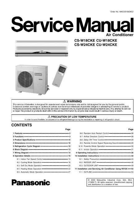
<strong>CS</strong>-<strong>W18CKE</strong> <strong>CU</strong>-<strong>W18CKE</strong><br />
<strong>CS</strong>-<strong>W24CKE</strong> <strong>CU</strong>-<strong>W24CKE</strong><br />
Order No. MAC0310029C2<br />
Air Conditioner<br />
Page Page<br />
8.6. Random Auto Restart Control 28<br />
8.7. Airflow Direction Control 28<br />
8.8. Delay ON Timer Control 29<br />
8.9. Remote Control Signal Receiving Sound 29<br />
8.10. Powerful Mode Operation 30<br />
8.11. Ionizer Operation 31<br />
9 Operating Instructions 35<br />
10 Installation Instructions 43<br />
10.1. Safety Precautions 43<br />
10.2. INDOOR UNIT 46<br />
10.3. OUTDOOR UNIT 49<br />
11 Installation and Servicing Air Conditioner Using R410A 53<br />
11.1. OUTLINE 53<br />
© 2003 Matsushita Industrial Corp. Sdn. Bhd.<br />
(11969-T). All rights reserved. Unauthorized copying<br />
and distribution is a violation of law.
<strong>CS</strong>-<strong>W18CKE</strong> <strong>CU</strong>-<strong>W18CKE</strong> / <strong>CS</strong>-<strong>W24CKE</strong> <strong>CU</strong>-<strong>W24CKE</strong><br />
11.2. TOOLS FOR INSTALLING/SERVICING REFRIGERANT<br />
PIPING 54<br />
11.3. REFRIGERANT PIPING WORK 58<br />
11.4. INSTALLATION, TRANSFERRING, SERVICING 60<br />
12 Servicing Information 64<br />
12.1. Indoor Electronic Controllers Removal Procedures<br />
12.2. Cross Flow Fan Indoor and Fan Motor Removal<br />
64<br />
Procedures 65<br />
13 Troubleshooting Guide 68<br />
13.1. Refrigeration cycle system 68<br />
14 Technical Data 70<br />
15 Exploded View 74<br />
16 Replacement Parts List 75<br />
17 Exploded View 76<br />
18 Replacement Parts List 77<br />
1 Features<br />
• High Efficiency<br />
• Compact Design<br />
• Comfort Environment<br />
− − Ionizer control for generate negative ion in discharge air<br />
− − − Air filter with function to reduce dust and smoke<br />
− − Wider range of horizontal discharge air<br />
− − New Automatic air swing and manual adjusted by<br />
remote control for horizontal airflow.<br />
• Auto Restart<br />
− − Random auto restart after power failure for safety restart<br />
operation<br />
• Removable and Washable Front Panel<br />
• Remote Control Self-illuminating Button<br />
• Catechin Air Purifying Filter<br />
− − − Trap dust, tobacco smoke and tiny particles<br />
− − Prevent the growth of bacteria and viruses trapped<br />
• Triple Deodorizing Filter<br />
− − − Absorb odours produced by wall paper, construction<br />
material and living environment<br />
2<br />
19 Electronic Circuit Diagram 78<br />
19.1. REMOTE CONTROL<br />
84<br />
19.2. PRINT PATTERNINDOOR UNIT PRINTED CIR<strong>CU</strong>IT<br />
BOARD<br />
TOP VIEW 85<br />
19.3. PRINT PATTERNINDOOR UNIT PRINTED CIR<strong>CU</strong>IT<br />
BOARD<br />
BOTTOM VIEW 86<br />
19.4. PRINT PATTERNOUTDOOR UNIT PRINTED CIR<strong>CU</strong>IT<br />
BOARD<br />
• Quality Improvement<br />
− Gas leakage protection<br />
− Prevent compressor reverse cycle<br />
− Inner protector<br />
− − Noise prevention during soft dry operation.<br />
− − Anti-dew Formation Control (Cooling & Soft Dry)<br />
− Overload Protection Control (Heating)<br />
− Outdoor Fan Control<br />
− Compressor High Pressure Control<br />
− Blue Coated Condenser<br />
− High resistance to corrosion.<br />
• Operation Improvement<br />
− Quiet mode to provide quiet operation<br />
− Powerful mode to reach the desired room temperature<br />
quickly<br />
• Long Installation Piping<br />
− Long piping up to 25 meter<br />
• 24-hour Timer Setting<br />
• Environmental Friendly<br />
− R410A, which does not contain chlorine, is used as its<br />
refrigerant, so there is no danger of damage to the<br />
ozone layer in stratosphere.<br />
87
2 Functions<br />
Remote Control<br />
OFF / ON<br />
MODE<br />
FAN SPEED<br />
AIR SWING<br />
POWERFUL<br />
QUIET<br />
Operation OFF / ON<br />
Operation Mode Selection<br />
• AUTO Automatic Operation Mode<br />
• HEAT Heating Operation Mode<br />
• COOL Cooling Operation Mode<br />
• DRY Soft Dry Operation Mode<br />
Indoor Fan Speed Selection<br />
• FAN Low Fan Speed<br />
• FAN Medium Fan Speed<br />
• FAN High Fan Speed<br />
• AUTO Automatic Fan Speed<br />
FAN<br />
Vertical Airflow Direction Control<br />
• Vertical Automatic Airflow<br />
Direction Control and Manual<br />
Airflow Direction Control (5<br />
stages of adjustment).<br />
• Horizontal Automatic Airflow<br />
Direction Control and Manual<br />
Airflow Direction Control (5<br />
stages of adjustment).<br />
Powerful Mode Operation OFF/ON<br />
Quiet Mode Operation OFF/ON<br />
3<br />
TEMP.<br />
TIME<br />
Room Temperature Setting<br />
ON-TIMER<br />
OFF-TIMER Timer Operation Selection<br />
SET<br />
CANCEL<br />
CLOCK<br />
Heating, Cooling, Soft Dry Operation.<br />
• Temperature Setting (16°C to 30°C)<br />
Automatic Operation<br />
• Operation with 2°C higher than<br />
standard temperature.<br />
• Operation with standard temperature.<br />
• Operation with 2°C lower than<br />
standard temperature.<br />
• 24-hour, OFF / ON Real Timer Setting.<br />
Time / Timer Setting<br />
• Hours and minutes setting.<br />
Timer Operation Set / Cancel<br />
• ON Timer and OFF Timer setting and<br />
cancellation.<br />
Clock Setting<br />
• Current time setting.<br />
<strong>CS</strong>-<strong>W18CKE</strong> <strong>CU</strong>-<strong>W18CKE</strong> / <strong>CS</strong>-<strong>W24CKE</strong> <strong>CU</strong>-<strong>W24CKE</strong><br />
Self illuminating<br />
button<br />
Ionizer Operation OFF / ON
<strong>CS</strong>-<strong>W18CKE</strong> <strong>CU</strong>-<strong>W18CKE</strong> / <strong>CS</strong>-<strong>W24CKE</strong> <strong>CU</strong>-<strong>W24CKE</strong><br />
Indoor Unit<br />
AUTO<br />
OFF / ON<br />
Automatic Operation Button<br />
• Press for < 5s to operate Automatic<br />
operation mode.<br />
(Used when the remote control cannot be used.)<br />
• Press continuously for 5s or < 10s to<br />
operate Test Run/Pump down. “Beep”<br />
sound will be heard at the 5th second.<br />
(Used when test running or servicing.)<br />
• Press continuously for 10s and above to<br />
omit or resume the remote control signal<br />
receiving sound. “Beep, beep” sound will<br />
be heard at the 10th second.<br />
Operation Indication Lamps (LED)<br />
• POWER (Green).......... Lights up in operation,<br />
blinks in Automatic<br />
Operation Mode judging<br />
and Hot Start operation.<br />
• QUIET (Orange) ......... Lights up in Quiet Mode<br />
Operation.<br />
• TIMER (Orange) ......... Lights up in Timer Setting.<br />
• POWERFUL (Orange) ... Lights up in Powerful<br />
Mode Operation.<br />
• ION (Green) ...... Lights up in Ionizer<br />
Mode Operation.<br />
Operation Mode<br />
• Heating, Cooling, Soft Dry and Automatic<br />
Mode.<br />
Powerful Operation<br />
• Reaches the desired room temperature quickly.<br />
Quiet Operation<br />
• To provide quiet operation.<br />
Random Auto Restart Control<br />
• Operation is restarted randomly after<br />
power failure at previous setting mode.<br />
Anti-Freezing Control<br />
• Anti-Freezing control for indoor heat<br />
exchanger. (Cooling and Soft Dry)<br />
4<br />
Ionizer Control<br />
• Ionizer control for generate negative ion<br />
in discharge air.<br />
Indoor Fan Speed Control<br />
• High, Medium and Low.<br />
• Automatic Fan Speed Mode<br />
– Heating : Fan speed varies from Me<br />
SSLo in accordance with<br />
indoor heat exchanger.<br />
– Cooling : Fan rotates at Hi, Me and<br />
Lo- speed. Deodorizing<br />
control is available.<br />
– Soft Dry : Fan rotates at Lo- speed.<br />
Deodorizing control is<br />
available.<br />
Airflow Direction Control<br />
• Automatic air swing and manual adjusted<br />
by remote control for vertical and horizontal<br />
airflow.<br />
Time Delay Safety Control<br />
• Restarting is inhibited for appro. 3 minutes.<br />
7 Minutes Time Save Control<br />
• Cooling Operation only.<br />
Anti-Dew Formation Control<br />
• Anti-Dew Formation Control for indoor unit<br />
discharge area.<br />
Hot-Start Control<br />
• At Heating Operation the indoor fan will<br />
operate at SLo speed when indoor heat<br />
exchanger temperature reaches 30°C.<br />
Anti Cold Draft Control<br />
• The indoor fan operates at Lo – (30 sec.)<br />
after that SSLo when the indoor heat<br />
exchanger temperature is low.<br />
(During Heating mode thermal off)
Outdoor Unit<br />
Compressor Reverse Rotation<br />
Protection Control<br />
• To protect compressor from reverse<br />
rotation when there is an instantaneous<br />
power failure.<br />
Overload Protector<br />
• Inner protector.<br />
60 Secs. Forced Operation Control<br />
• Once the compressor is activated, it<br />
does not stop within the first 60 secs.<br />
However, it stops immediately with<br />
remote control stop signal.<br />
Outdoor Fan Operation Control<br />
• 6-pole induction motor (2 speed).<br />
• For Cooling or Soft Dry operation<br />
Hi-speed ............. When outdoor<br />
temperature reaches to 31°C.<br />
Lo-speed ............. When outdoor<br />
temperature reaches to 29°C.<br />
• For Heating operation<br />
Hi-speed ............. When outdoor<br />
temperature reaches to 13.5°C.<br />
Lo-speed ............. When outdoor<br />
temperature reaches to 15.5°C.<br />
• For Over-heating Protection, the Fan is<br />
switched ON or OFF depending on the<br />
piping temperature and the outdoor<br />
temperature.<br />
5<br />
Deice Control<br />
• To prevent frosting at outdoor heat<br />
exchanger during Heating Operation.<br />
4-Way Valve Control<br />
<strong>CS</strong>-<strong>W18CKE</strong> <strong>CU</strong>-<strong>W18CKE</strong> / <strong>CS</strong>-<strong>W24CKE</strong> <strong>CU</strong>-<strong>W24CKE</strong><br />
• When the unit is switched to “OFF”<br />
during Heating Operation, 4-way valve<br />
stays at Heating position for 5 minutes.
<strong>CS</strong>-<strong>W18CKE</strong> <strong>CU</strong>-<strong>W18CKE</strong> / <strong>CS</strong>-<strong>W24CKE</strong> <strong>CU</strong>-<strong>W24CKE</strong><br />
3 Product Specifications<br />
Unit <strong>CS</strong>-<strong>W18CKE</strong> <strong>CU</strong>-<strong>W18CKE</strong><br />
Power Source Phase, Voltage, Cycle Single, 230, 50 Hz<br />
Cooling Capacity kW (BTU/h) 5.30 (18,100)<br />
Heating Capacity kW (BTU/h) 5.55 (18,900)<br />
Moisture Removal l/h (Pint/h) 2.9 (6.1)<br />
Airflow Method OUTLET<br />
INTAKE<br />
SIDE VIEW TOP VIEW<br />
Air Volume Indoor Air (Lo) m 3 /min (cfm) Cooling; 13.3 (470)<br />
Heating; 14.2 (500)<br />
25.6 (904)<br />
Indoor Air (Me) m 3 /min (cfm) Cooling; 14.8 (520)<br />
Heating; 14.8 (520)<br />
—<br />
Indoor Air (Hi) m 3 /min (cfm) Cooling; 15.6 (550)<br />
Heating; 16.4 (580)<br />
40.0 (1,410)<br />
Indoor Air (SHi) m 3 /min (cfm) Cooling; 16.4 (580)<br />
Heating; 16.4 (580)<br />
—<br />
Noise Level dB (A) Cooling; High 43, Low 38<br />
Cooling; High 55<br />
Heating; High 42, Low 38<br />
Heating; High 56<br />
Power level dB Cooling; 55<br />
Cooling; 68<br />
Heating; 53<br />
Heating; 69<br />
Electrical Data Input Power kW Cooling; 1.65<br />
Heating; 1.70<br />
Running Current A Cooling; 7.4<br />
Heating; 7.6<br />
EER W/W (BTU/hW) Cooling; 3.21 (10.95)<br />
COP W/W (BTU/hW) Heating; 3.26 (11.13)<br />
Starting Current A 27.0<br />
Piping Connection Port<br />
inch<br />
G ; Half Union 1/2”<br />
G ; 3-way valve 1/2”<br />
(Flare piping)<br />
inch<br />
L ; Half Union 1/4”<br />
L ; 2-way valve 1/4”<br />
Pipe Size<br />
inch<br />
G ; (gas side) 1/2”<br />
G ; (gas side) 1/2”<br />
(Flare piping)<br />
inch<br />
L ; (liquid side) 1/4”<br />
L ; (liquid side) 1/4”<br />
Drain<br />
Inner diameter mm 12 —<br />
Hose<br />
Length mm 650 —<br />
Power Cord Length m 1.9 —<br />
Number of core-wire 3 (1.5 mm 2 ) —<br />
Dimensions Height inch (mm) 10 - 13/16 (275) 26 - 31/32 (685)<br />
Width inch (mm) 39 - 9/32 (998) 31 - 1/2 (800)<br />
Depth inch (mm) 8 - 9/32 (210) 11 - 13/16 (300)<br />
Net Weight lb (kg) 24 (11.0) 121 (55.0)<br />
Compressor Type — Rotary (1 cylinder)<br />
rolling piston type<br />
Motor Type — Induction (2-poles)<br />
Rated Output kW — 1.4<br />
6
Unit <strong>CS</strong>-<strong>W18CKE</strong> <strong>CU</strong>-<strong>W18CKE</strong><br />
Air Circulation Type Cross-flow Fan Propeller Fan<br />
Material ASHT-18 PP<br />
Motor Type Transistor (8-poles) Induction (4-poles)<br />
Input W 53.5 130<br />
Rated Output W 30 67<br />
Fan Speed Low rpm Cooling; 1,160<br />
Heating; 1,240<br />
640<br />
Medium rpm Cooling; 1,290<br />
Heating; 1,290<br />
—<br />
High rpm Cooling; 1,380<br />
Heating; 1,440<br />
1,000<br />
SuperHigh rpm Cooling; 1,440<br />
Heating; 1,440<br />
—<br />
Heat Exchanger Description Evaporator Condenser<br />
Tube material Copper Copper<br />
Fin material Aluminium (Pre Coat) Aluminium (Blue Coat)<br />
Fin Type Slit Fin Corrugated Fin<br />
Row / Stage (Plate fin configuration, forced draft)<br />
2×15 2×26<br />
FPI 21 16<br />
Size (W × H × L) mm 810 × 315 × 25.4 769.2 × 660.4 × 44<br />
732.9<br />
Refrigerant Control Device — Capillary Tube<br />
Refrigeration Oil (cm 3 ) — RB68A OR FRE0L ALPHA 68M<br />
(670)<br />
Refrigerant (R410A) g (oz) — 1,620 (57.2)<br />
Thermostat Electronic Control Electronic Control<br />
Protection Device — Inner Protector<br />
Capillary Tube Length mm — Cooling; 1,180, Heating; 1,048<br />
Flow Rate l/min — Cooling; 8.7, Heating; 14.0<br />
Inner Diameter mm — Cooling; 1.5, Heating; 1.8<br />
Air Filter Material<br />
P.P.<br />
—<br />
Style<br />
Honeycomb<br />
Capacity Control Capillary Tube<br />
Compressor Capacitor µF, VAC — 50 µF, 370VAC<br />
Fan Motor Capacitor µF, VAC — 3.0 µF, 450VAC<br />
Note:<br />
• • Specifications are subject to change without notice for further improvement.<br />
7<br />
<strong>CS</strong>-<strong>W18CKE</strong> <strong>CU</strong>-<strong>W18CKE</strong> / <strong>CS</strong>-<strong>W24CKE</strong> <strong>CU</strong>-<strong>W24CKE</strong>
<strong>CS</strong>-<strong>W18CKE</strong> <strong>CU</strong>-<strong>W18CKE</strong> / <strong>CS</strong>-<strong>W24CKE</strong> <strong>CU</strong>-<strong>W24CKE</strong><br />
Unit <strong>CS</strong>-<strong>W24CKE</strong> <strong>CU</strong>-<strong>W24CKE</strong><br />
Power Source Phase, Voltage, Cycle Single, 230, 50 Hz<br />
Cooling Capacity kW (BTU/h) 7.03 (24,000)<br />
Heating Capacity kW (BTU/h) 7.72 (26,300)<br />
Moisture Removal l/h (Pint/h) 4.0 (8.5)<br />
Airflow Method OUTLET<br />
INTAKE<br />
SIDE VIEW TOP VIEW<br />
Air Volume Indoor Air (Lo) m 3 /min (cfm) Cooling; 14.4 (510)<br />
Heating; 15.6 (550)<br />
27.4 (970)<br />
Indoor Air (Me) m 3 /min (cfm) Cooling; 16.4 (580)<br />
Heating; 16.4 (580)<br />
—<br />
Indoor Air (Hi) m 3 /min (cfm) Cooling; 17.5 (620)<br />
Heating; 18.1 (640)<br />
47.2 (1,670)<br />
Indoor Air (SHi) m 3 /min (cfm) Cooling; 18.1 (640)<br />
Heating; 18.1 (640)<br />
—<br />
Noise Level dB (A) Cooling; High 47, Low 41<br />
Cooling; High 60<br />
Heating; High 46, Low 41<br />
Heating; High 61<br />
Power level dB Cooling; 59<br />
Coolling; 74<br />
Heating; 57<br />
Heating; 74<br />
Electrical Data Input Power kW Cooling; 2.78<br />
Heating; 2.69<br />
Running Current A Cooling; 13.1<br />
Heating; 12.9<br />
EER W/W (BTU/hW) Cooling; 2.53 (8.63)<br />
COP W/W (BTU/hW) Heating; 2.87 (9.79)<br />
Starting Current A 65.0<br />
Piping Connection Port<br />
inch<br />
G ; Half Union 5/8”<br />
G ; 3-way valve 5/8”<br />
(Flare piping)<br />
inch<br />
L ; Half Union 1/4”<br />
L ; 2-way valve 1/4”<br />
Pipe Size<br />
inch<br />
G ; (gas side) 5/8”<br />
G ; (gas side) 5/8”<br />
(Flare piping)<br />
inch<br />
L ; (liquid side) 1/4”<br />
L ; (liquid side) 1/4”<br />
Drain<br />
Inner diameter mm 12 —<br />
Hose<br />
Length mm 650 —<br />
Power Cord Length m 1.9 —<br />
Number of core-wire 3 (2.5 mm 2 ) —<br />
Dimensions Height inch (mm) 10 - 13/16 (275) 26 - 31/32 (685)<br />
Width inch (mm) 39 - 9/32 (998) 31 - 1/2 (800)<br />
Depth inch (mm) 8 - 9/32 (210) 11 - 13/16 (300)<br />
Net Weight lb (kg) 24 (11.0) 135 (61.0)<br />
Compressor Type — Rotary (1 cylinder) rolling piston<br />
type<br />
Motor Type — Induction (2-poles)<br />
Rated Output kW — 2.2<br />
8
Unit <strong>CS</strong>-<strong>W24CKE</strong> <strong>CU</strong>-<strong>W24CKE</strong><br />
Air Circulation Type Cross-flow Fan Propeller Fan<br />
Material ASHT-18 PC + AES + Glass Fiber 15%<br />
Motor Type Transistor (8-poles) Induction (4-poles)<br />
Input W 53.5 190.0<br />
Rated Output W 30 108<br />
Fan Speed Low rpm Cooling; 1,260<br />
Heating; 1,360<br />
680<br />
Medium rpm Cooling; 1,430<br />
Heating; 1,430<br />
—<br />
High rpm Cooling; 1,530<br />
Heating; 1,580<br />
1,170<br />
SuperHigh rpm Cooling; 1,580<br />
Heating; 1,580<br />
—<br />
Heat Exchanger Description Evaporator Condenser<br />
Tube material Copper Copper<br />
Fin material Aluminium (Pre Coat) Aluminium (Blue Coat)<br />
Fin Type Slit Fin Corrugated Fin<br />
Row / Stage (Plate fin configuration, forced draft)<br />
2×15 2×26<br />
FPI 21 16<br />
Size (W × H × L) mm 810 × 315 × 25.4 769.2 × 660.4 × 44.0<br />
732.9<br />
Refrigerant Control Device — Capillary Tube<br />
Refrigeration Oil (cm 3 ) — RB68A OR FRE0L ALPHA 68M<br />
(1,130)<br />
Refrigerant (R410A) g (oz) — 1,780 (62.8)<br />
Thermostat Electronic Control Electronic Control<br />
Protection Device — Inner Protector<br />
Capillary Tube Length mm — Cooling; 663, Heating; 550<br />
Flow Rate l/min — Cooling; 13.0, Heating; 29.0<br />
Inner Diameter mm — Cooling; 1.6, Heating; 2.4<br />
Air Filter Material<br />
P.P.<br />
—<br />
Style<br />
Honeycomb<br />
Capacity Control Capillary Tube<br />
Compressor Capacitor µF, VAC — 45 µF, 370VAC<br />
Fan Motor Capacitor µF, VAC — 3.0 µF, 450VAC<br />
Note:<br />
• • Specifications are subject to change without notice for further improvement.<br />
9<br />
<strong>CS</strong>-<strong>W18CKE</strong> <strong>CU</strong>-<strong>W18CKE</strong> / <strong>CS</strong>-<strong>W24CKE</strong> <strong>CU</strong>-<strong>W24CKE</strong>
<strong>CS</strong>-<strong>W18CKE</strong> <strong>CU</strong>-<strong>W18CKE</strong> / <strong>CS</strong>-<strong>W24CKE</strong> <strong>CU</strong>-<strong>W24CKE</strong><br />
4 Dimensions<br />
10
11<br />
<strong>CS</strong>-<strong>W18CKE</strong> <strong>CU</strong>-<strong>W18CKE</strong> / <strong>CS</strong>-<strong>W24CKE</strong> <strong>CU</strong>-<strong>W24CKE</strong>
<strong>CS</strong>-<strong>W18CKE</strong> <strong>CU</strong>-<strong>W18CKE</strong> / <strong>CS</strong>-<strong>W24CKE</strong> <strong>CU</strong>-<strong>W24CKE</strong><br />
5 Refrigeration Cycle Diagram<br />
12
6 Block Diagram<br />
13<br />
<strong>CS</strong>-<strong>W18CKE</strong> <strong>CU</strong>-<strong>W18CKE</strong> / <strong>CS</strong>-<strong>W24CKE</strong> <strong>CU</strong>-<strong>W24CKE</strong>
<strong>CS</strong>-<strong>W18CKE</strong> <strong>CU</strong>-<strong>W18CKE</strong> / <strong>CS</strong>-<strong>W24CKE</strong> <strong>CU</strong>-<strong>W24CKE</strong><br />
7 Wiring Diagram<br />
14
8 Operation Details<br />
8.1. Indoor Fan Speed Control<br />
• • • Auto Fan Speed Control<br />
When set to Auto Fan Speed, the fan speed is adjusted between maximum and minimum setting as shown in the table.<br />
• • Manual Fan Speed Control<br />
Basic fan speed adjustment (3 settings, from Lo to Hi) can be carried out by using the Fan Speed selection button at the remote<br />
control.<br />
Speed COOL, DRY Heat <strong>CS</strong>-<strong>W24CKE</strong> <strong>CS</strong>-<strong>W18CKE</strong><br />
SHi Hi 1580 1440<br />
Hi 1530 1380<br />
Me Me 1430 1290<br />
Lo+ Lo 1360 1240<br />
Lo 1260 1160<br />
Lo- Lo- 1070 980<br />
SLo SLo 830 760<br />
SS Lo SS Lo 300 300<br />
Q SHi QHi 1480 1340<br />
QHi 1430 1280<br />
QMe QMe 1330 1190<br />
QLo 1260 1140<br />
QLo 1160 1060<br />
15<br />
<strong>CS</strong>-<strong>W18CKE</strong> <strong>CU</strong>-<strong>W18CKE</strong> / <strong>CS</strong>-<strong>W24CKE</strong> <strong>CU</strong>-<strong>W24CKE</strong>
<strong>CS</strong>-<strong>W18CKE</strong> <strong>CU</strong>-<strong>W18CKE</strong> / <strong>CS</strong>-<strong>W24CKE</strong> <strong>CU</strong>-<strong>W24CKE</strong><br />
8.2. Cooling Mode Operation<br />
Cooling in operation according to Remote Control setting.<br />
Time Delay Safety Control (3 minutes)<br />
• When the compressor is stopped by Remote Control, it restarts after 3 minutes when the Remote Control is turned ON.<br />
• When the setting temperature is reached during cooling operation, the compressor stops and it will not start for 3 minutes.<br />
7 minutes Time Save Control<br />
• The compressor will start automatically if it has stopped for 7 minutes even if the room temperature is between the compressor<br />
ON temperature and OFF temperature.<br />
Anti-Freezing Control<br />
• If the temperature of the indoor heat exchanger falls<br />
continuously below 2°C for 4 minutes or more, the<br />
compressor turns off to protect the indoor heat exchanger<br />
from freezing. The fan speed setting remains the same.<br />
• Compressor will restart again when the indoor heat<br />
exchanger temperature rises to 10°C (Recovery).<br />
3 minutes waiting of Time Delay Safety Control is valid for<br />
Cooling Operation.<br />
Compressor Reverse Rotation Protection Control<br />
• If the compressor is operating continuously for 5 minutes or longer and the temperature difference between intake air and<br />
indoor heat exchanger is 2.5°C or less for 2 minutes, compressor will stop and restart automatically.<br />
(Time Delay Safety Control is valid)<br />
! T = Intake air temperature - Indoor heat exchanger temperature<br />
This is to protect reverse rotation of the compressor when there is an instantaneous power failure.<br />
Anti-Dew Formation Control<br />
• Purpose is to prevent dew formation on indoor unit air discharge area.<br />
• When room temperature is constant (±1°C) the following conditions occur for 30 minutes continuously, anti-dew formation will<br />
activate:<br />
− − − Indoor intake air temperature is more than 24°C and less than 30°C.<br />
− − Remote Control setting temperature is less than 25°C.<br />
− − Compressor is on.<br />
− − − Cooling operation mode.<br />
− − Indoor Fan motor operate at Low fan speed or QLo.<br />
• This control is cancelled immediately when above condition is changed.<br />
• Anti-Dew formation is control by:<br />
1. Lo fan speed<br />
Lo fan is changed to Lo+ fan<br />
16
2. QLo fan speed (Transistor Motor)<br />
3. QLo fan speed (Induction Motor)<br />
Automatic Fan Speed Mode<br />
When Automatic Fan Speed is selected at Remote Control during cooling operation.<br />
• • Fan speed rotates in the range of Hi to Me.<br />
• • Deodorizing Control.<br />
17<br />
<strong>CS</strong>-<strong>W18CKE</strong> <strong>CU</strong>-<strong>W18CKE</strong> / <strong>CS</strong>-<strong>W24CKE</strong> <strong>CU</strong>-<strong>W24CKE</strong>
<strong>CS</strong>-<strong>W18CKE</strong> <strong>CU</strong>-<strong>W18CKE</strong> / <strong>CS</strong>-<strong>W24CKE</strong> <strong>CU</strong>-<strong>W24CKE</strong><br />
Cooling Operation Time Diagram<br />
Quiet Operation Control<br />
(For Cooling Mode or cooling region of Soft Dry Mode)<br />
• Purpose of this operation is to provide quite cooling operation compare to normal operation.<br />
• When the Quiet Mode is set at the remote control, Quiet Mode LED illuminates, the sound level will be automatically decreased<br />
3 dB, against the present sound level operation.<br />
• Quiet setting of fan speed rpm refer to Indoor Fan Speed Control.<br />
• Dew formation become severe at Quiet Lo cool, therefore:<br />
i) For Transistor Motor<br />
Quiet Lo Cool is operated only 1h 30 minute (1h QLo, 30 min QLo+100). After that, it goes back to QLo+180 rpm. (However<br />
quiet LED remains on).<br />
ii) For Induction Motor<br />
Quiet Lo Cool is operated only 1h 30 minute (1h QLo, 30 min QLo+80). After that, it goes back to QLo+170 rpm. (However quiet<br />
LED remains on).<br />
18
• • • Manual Fan Speed:-<br />
− − RPM control during Lo cool<br />
− − RPM control during Hi & Me cool<br />
• • • Auto Fan Speed:-<br />
• • • Quiet Mode Operation will stop if:-<br />
− − − Quiet mode button is pressed again.<br />
− − − Stopped by ON/OFF switch.<br />
− − Timer OFF activates.<br />
− − Powerful mode button is pressed.<br />
19<br />
<strong>CS</strong>-<strong>W18CKE</strong> <strong>CU</strong>-<strong>W18CKE</strong> / <strong>CS</strong>-<strong>W24CKE</strong> <strong>CU</strong>-<strong>W24CKE</strong>
<strong>CS</strong>-<strong>W18CKE</strong> <strong>CU</strong>-<strong>W18CKE</strong> / <strong>CS</strong>-<strong>W24CKE</strong> <strong>CU</strong>-<strong>W24CKE</strong><br />
8.3. Soft Dry Mode Operation<br />
• The unit starts cooling operation until the room temperature reaches the setting temperature set on the Remote Control, and<br />
then Soft Dry operation will start.<br />
• During Soft Dry operation, the Indoor Fan will operate at Lo- speed.<br />
• Once room temperature reaches below Soft Dry OFF temperature. Indoor Fan, Compressor and Outdoor Fan stop for 6<br />
minutes.<br />
Time Delay Safety Control<br />
• Once the compressor stops, it will not start for 3 minutes during Cooling operation.<br />
Anti-Freezing Control<br />
• Same as Anti-Freezing Control for Cooling Mode operation. (For Soft Dry region, 6 minutes waiting is valid during compressor<br />
stops.)<br />
Compressor Reverse Rotation Protection Control<br />
• Same as Compressor Reverse Rotation Protection Control for Cooling Mode Operation. (For Soft Dry region, 6 minutes waiting<br />
is valid during compressor stops.)<br />
Anti-Dew Formation Control<br />
• Same as Anti-Dew Formation Control for Cooling Mode operation.<br />
Automatic Fan Speed Mode<br />
When Automatic Fan Speed is selected at Remote Control during Soft Dry operation.<br />
• • Fan speed off and on at Lo- speed.<br />
• • Deodorizing Control.<br />
20
Soft Dry Operation Time Diagram<br />
Quiet Operation Control<br />
• • Same as Quiet Operation Control for Cooling Mode operation.<br />
21<br />
<strong>CS</strong>-<strong>W18CKE</strong> <strong>CU</strong>-<strong>W18CKE</strong> / <strong>CS</strong>-<strong>W24CKE</strong> <strong>CU</strong>-<strong>W24CKE</strong>
<strong>CS</strong>-<strong>W18CKE</strong> <strong>CU</strong>-<strong>W18CKE</strong> / <strong>CS</strong>-<strong>W24CKE</strong> <strong>CU</strong>-<strong>W24CKE</strong><br />
8.4. Heating Mode Operation<br />
• Heating in operation according to Remote Control setting.<br />
Time Delay Safety Control<br />
• When the compressor is stopped by Power Switch, Remote Control or there is a power failure, it restarts after 3 minutes when<br />
the Power Switch, Remote Control is turned ON or the power supply is resumed.<br />
• When the setting temperature is reached during heating operation, the compressor stops and it will not start for 4 minutes.<br />
(a) Outdoor Fan Control<br />
Overload Protection Control<br />
• • If the temperature of the Outdoor Heat Exchanger less than -3°C, Outdoor Fan is ON. The Outdoor Fan stop, when Outdoor<br />
Heat Exchanger temperature is Tb or more according to Outdoor Air Temperature region as table below:<br />
The Outdoor Fan restarts when the indoor heat exchanger temperature falls to 49°C.<br />
During starting of Heating mode and after deice, Outdoor Fan ON for 90 sec. (Hi).<br />
(b) Compressor High Pressure Control<br />
• • If the indoor heat exchanger becomes 68°C or more, the compressor will stop and restart automatically.<br />
(Time Delay Safety Control - 4 minutes waiting).<br />
4-way Valve Control<br />
• 4-way valve ON during Heating operation, except deicing operation.<br />
• When the unit is switched to “OFF” during Heating operation, 4-way valve stays at Heating position for 5 minutes.<br />
Hot Start Control<br />
When Heating operation starts, Indoor Fan will not start until the indoor heat exchanger reaches 30°C as diagram shown.<br />
Hot Start is completed when indoor heat exchanger reaches 42°C.<br />
Maximum Hot start duration = 4 minutes. After 4 minutes,<br />
Hot start operation will be shifted to normal Heating operation.<br />
22
Automatic Fan Speed Mode<br />
When Automatic Fan Speed is selected at Remote Control during heating operation.<br />
• • Fan speed rotates in the range of Me → SLo according to the heat exchanger temperature.<br />
Anti Cold Draft Control<br />
Compressor Reverse Rotation Protection Control<br />
• • • If the compressor is operating continuously for 5 minutes or longer and the temperature difference between indoor heat<br />
exchanger and intake air is 5°C or less for 2 minutes, compressor will stop and restart automatically.<br />
(Time Delay Safety Control is valid)<br />
! T = Indoor heat exchanger temperature - Intake air temperature<br />
This is to protect reverse rotation of the compressor when there is an instantaneous power failure.<br />
23<br />
<strong>CS</strong>-<strong>W18CKE</strong> <strong>CU</strong>-<strong>W18CKE</strong> / <strong>CS</strong>-<strong>W24CKE</strong> <strong>CU</strong>-<strong>W24CKE</strong>
<strong>CS</strong>-<strong>W18CKE</strong> <strong>CU</strong>-<strong>W18CKE</strong> / <strong>CS</strong>-<strong>W24CKE</strong> <strong>CU</strong>-<strong>W24CKE</strong><br />
Heating Operation Time Diagram<br />
Deicing Control<br />
Deice starts to prevent frosting at outdoor heat exchanger.<br />
• • Normal Deicing<br />
Deice operation detection commences in Heating operation starts or 60 minutes after previous deice operation. If the<br />
outdoor piping temperature drops to -4°C for 50 sec. continuously during compressor is in operation, deice will start.<br />
(There is no detection during Outdoor Fan stops.)<br />
• • Overload Deicing<br />
During heating operation, if the outdoor Fan OFF duration (due to overload control) is accumulated up to 60 minutes and<br />
after compressor starts for 1 minutes, deicing starts.<br />
• • Deicing ends when<br />
(a) 12 minutes after deicing operation starts;<br />
(b) The outdoor piping temperature rises to about 12°C.<br />
• • After deicing operation, compressor stops for 30 seconds and 4-way valve stays at cooling position for 10 seconds.<br />
24
a) Normal Deicing Time Diagram<br />
(b) Overload Deicing Time Diagram<br />
25<br />
<strong>CS</strong>-<strong>W18CKE</strong> <strong>CU</strong>-<strong>W18CKE</strong> / <strong>CS</strong>-<strong>W24CKE</strong> <strong>CU</strong>-<strong>W24CKE</strong>
<strong>CS</strong>-<strong>W18CKE</strong> <strong>CU</strong>-<strong>W18CKE</strong> / <strong>CS</strong>-<strong>W24CKE</strong> <strong>CU</strong>-<strong>W24CKE</strong><br />
(For Heating Mode)<br />
Quiet Operation Control<br />
• • Purpose of this operation is to provide quite heating operation compare to normal operation.<br />
• • When the Quiet Mode is set at the remote control, Quiet Mode LED illuminates, the sound level will be automatically<br />
decreased 3 dB, against the present sound level operation.<br />
• • Quiet setting of fan speed rpm refer to Indoor Fan Speed Control.<br />
• • Manual Fan Speed:-<br />
− − − Rpm control during Lo, Me & Hi Cool<br />
• • Auto Fan Speed:-<br />
− − Rpm control depends on the piping air temperature sensor of Indoor heat exchanger<br />
• • Quiet Mode Operation will stop if:-<br />
− − Quiet mode button is pressed again.<br />
− − Stopped by ON/OFF switch.<br />
− − Timer OFF activates.<br />
− − Powerful mode button is pressed.<br />
26
8.5. Automatic Mode Operation<br />
1. When the Automatic Mode Operation is selected, the indoor fan operates at SLo fan speed for 25 seconds to sense intake air<br />
temperature and determine the 1st operation mode. If indoor intake air temperature is less than 16°C, Heating mode will<br />
immediate operate.<br />
2. Operation mode will be determine again after 1 hour of operation, if the room temperature reaches to set temperature and<br />
compressor off time is over 7 minutes 30 seconds continuously.<br />
The present operation mode will be continued, if the room temperature does not reach to set temperature (Compressor keeps running)<br />
eventhough after 1 hour from automatic operation mode started.<br />
Present Judgement Next Mode<br />
Mode Cooling Soft Dry Heating<br />
O O<br />
Cooling 23°C Cooling (Judgement: Not Applicable (Judgement:<br />
Heating 23°C & Above) Below 23°C)<br />
O O<br />
Soft Dry 20°C Soft Dry Not Applicable (Judgement: (Judgement:<br />
Heating 20°C & Above) Below 20°C)<br />
O O<br />
Heating Cooling (Judgement: Not Applicable (Judgement:<br />
25°C Heating Above 25°C) 25°C & below)<br />
Automatic Set Temperature<br />
Refer 3. as below.<br />
3. Automatic Set Temperature<br />
For each operation, set temperature will automatically set as shown below.<br />
However it can be selected 2°C higher or 2°C lower from standard set temperature by pressing the “Room Temperature Setting<br />
button”.<br />
Operation Hi (Standard) Lo<br />
(+2°C) (±0°C) (-2°C)<br />
Cooling 27°C 25°C 23°C<br />
Soft Dry 24°C 22°C 20°C<br />
Heating 23°C 21°C 19°C<br />
• • The mode judging temperature and standard setting temperature can be increased by 2°C, by open the circuit of JX1 at<br />
indoor electronic controller.<br />
27<br />
<strong>CS</strong>-<strong>W18CKE</strong> <strong>CU</strong>-<strong>W18CKE</strong> / <strong>CS</strong>-<strong>W24CKE</strong> <strong>CU</strong>-<strong>W24CKE</strong>
<strong>CS</strong>-<strong>W18CKE</strong> <strong>CU</strong>-<strong>W18CKE</strong> / <strong>CS</strong>-<strong>W24CKE</strong> <strong>CU</strong>-<strong>W24CKE</strong><br />
8.6. Random Auto Restart Control<br />
• If there is a power failure during air conditioner operation, operation will be automatically restarted after 3 to 4 minutes when the<br />
power is resumed.<br />
It will start with previous operation mode and airflow direction.<br />
• Restart time is decided randomly using 4 parameter:-<br />
Intake air temperature, setting temperature, fan speed and Air Swing Blade position.<br />
• Auto Restart Control is not available when Timer is set.<br />
• This control can be omitted by open the circuit of JX2. (Refer Circuit Diagram)<br />
8.7. Airflow Direction Control<br />
Vertical Airflow Direction Auto-Control<br />
• When set an Airflow Direction Auto-Control with remote<br />
control, the louver swings up and down as shown in the<br />
diagram.<br />
• The louver does not swing when the Indoor Fan Motor<br />
stops during operation at the upper limit.<br />
• When stopped with remote control, the discharge vent is<br />
reset, and stopped at the closing position.<br />
• During Anti-dew condensation prevention, Airflow Direction<br />
Auto-control angle change from 0° - 36° to 12° - 28° under<br />
Cooling and Soft Dry operation mode.<br />
1. There is no swinging while indoor fan motor is stopped during Cooling, Ion and Soft Dry operation.<br />
2. In Heating operation, when the piping air temperature reaches 38°C, the louver is changed from upper to lower limit position. When the<br />
piping air temperature falls to 35°C, the louver is changed from lower to upper limit position.<br />
Vertical Airflow Direction manual Control<br />
• When the manual Airflow Direction Selection Button is<br />
pressed, the automatic airflow is released and the airflow<br />
direction louver move up and down in the range shown in<br />
the diagram.<br />
The louver can be adjusted by pressing the button to the<br />
desired louver position.<br />
• When the remote control is used to stop the operation, the<br />
discharge vent is reset, and stopped at the closing position.<br />
• During Anti-dew condensation prevention, Airflow Direction<br />
Manual control angle change from 14°, 19°, 24°, 30°, 36° to<br />
16°, 18°, 20°, 22°, 24° under Cooling and Soft Dry operation<br />
mode.<br />
28
Horizontal Airflow Direction Auto-Control<br />
• • • When set a Airflow Direction Auto-Control with remote<br />
control, the vanes swings left and right as shown in the<br />
diagram.<br />
• • The vanes does not swing when the Indoor Fan Motor stops<br />
during operation at 22° angle.<br />
• • When stopped with remote control, the discharge vent is<br />
reset, and stopped at the reset position.<br />
• • During Anti-dew condensation prevention, Airflow Direction<br />
Auto-control angle change from 0° - 44° to 14° - 30° under<br />
Cooling and Soft Dry operation mode.<br />
1. There is no swinging while indoor fan motor is stopped during Cooling, Ion and Soft Dry operation.<br />
2. In Heating operation, when the piping air temperature reaches 38°C, the airflow direction is Auto Swing left and right (8°-36°). When the<br />
piping air temperature falls to 35°C, the airflow direction is stop at 22° angle.<br />
Horizontal Airflow Direction manual Control<br />
• • • When the manual Airflow Direction Selection Button is<br />
pressed, the automatic airflow is released and the airflow<br />
direction vane move left and right in the range shown in the<br />
diagram.<br />
The louver can be adjusted by pressing the button to the<br />
desired vane position.<br />
• • • When the remote control is used to stop the operation, the vanes is reset, and stopped at reset position.<br />
• • During Anti-dew condensation prevention, Airflow Direction Manual control angle change from 0°, 11°, 22°, 33°, 44° to 14°, 18°,<br />
22°, 26°, 30° under Cooling and Soft Dry operation mode.<br />
8.8. Delay ON Timer Control<br />
• • • When the Delayed ON Timer is set by using the remote control, the unit will start operate slightly before the set time, so that<br />
the room will reach nearly to the set temperature by the desired time.<br />
• • For Cooling and Soft Dry mode, the operation will start 15 minutes before the set time.<br />
• • For Heating mode, the operation will start 30 minutes before the set time.<br />
• • • For Automatic mode, the indoor fan will operate at SLo speed for 25 seconds, 30 minutes before the set time to detect the<br />
intake air temperature to determine the operation mode. The operation indication lamp will blink at this time.<br />
8.9. Remote Control Signal Receiving Sound<br />
• • • Long beep sound will be heard when:-<br />
− − − Stopping the Air Conditioner using ON/OFF switch.<br />
− − Stopping the Quiet Mode.<br />
− − Stopping the Powerful Mode.<br />
− − Stopping the Ion Mode.<br />
• • Short beep sound will be heard for others.<br />
• • To switch off the beep sound:-<br />
Press the “Automatic Operation Button” continuously for 10 seconds or more (“beep” “beep” will be heard at the 10th second).<br />
Repeat the above if you want to switch ON the beep sound.<br />
However, if the “Automatic Operation Button” has been pressed the Automatic operation will be activated.<br />
If you do not require this operation, you may change it by using the remote control.<br />
29<br />
<strong>CS</strong>-<strong>W18CKE</strong> <strong>CU</strong>-<strong>W18CKE</strong> / <strong>CS</strong>-<strong>W24CKE</strong> <strong>CU</strong>-<strong>W24CKE</strong>
<strong>CS</strong>-<strong>W18CKE</strong> <strong>CU</strong>-<strong>W18CKE</strong> / <strong>CS</strong>-<strong>W24CKE</strong> <strong>CU</strong>-<strong>W24CKE</strong><br />
8.10. Powerful Mode Operation<br />
Purpose of this operation is to be obtain the setting temperature quickly.<br />
1. Cooling and Soft Dry Mode<br />
• • When the Powerful Mode is set, the set temperature will be automatically decreased 3°C against the present setting<br />
temperature (Lower temperature: 16°C). This operation automatically will be running under SHi Fan Speed (Cooling), Lo-<br />
Fan Speed (Soft Dry).<br />
• • Vertical Airflow Direction:-<br />
In “Manual” setting, the vane will automatically shift down 10° lower than previous setting.<br />
In “Auto” setting, the vane will automatically swing up and down. However the upper and lower limit will be shifted 10°<br />
downward.<br />
2. Heating Mode<br />
• • When the Powerful Mode is set, the set temperature will be automatically increased 3°C against the present setting<br />
temperature (Higher temperature: 30°C).<br />
• • The Fan Speed will shift as shown below:<br />
• • Vertical Airflow Direction:-<br />
In “Manual” setting, the vane will automatically shift down 5° lower than previous setting.<br />
In “Auto” setting, the vane will automatically shift between upper and lower limit depending on the intake air temperature as<br />
Heating Mode, Airflow Direction Auto-Control. However the upper and lower limit will be shifted 5° downward.<br />
3. Powerful mode will operate for 15 minutes only.<br />
4. Powerful Mode will stop if:<br />
• • Powerful mode button is pressed again.<br />
• • Stopped by ON / OFF switch.<br />
• • • Timer-off activates.<br />
• • Quiet mode button is pressed.<br />
• • Operating mode button is changed.<br />
30
8.11. Ionizer Operation<br />
Purpose<br />
To provide fresh air effect to user by discharging minus Ion to air.<br />
Control Condition<br />
a. Ionizer Only Operation.<br />
1. When air-conditioner unit is at “OFF” condition (standby) and ION operation button at remote control is pressed.<br />
Fan & ionizer on, ION LED illuminates, but power LED maintain off. (1 → 2)<br />
However, fan speed can be adjusted later by customer during this operation.<br />
Airflow direction (Horizontal Vane) control:<br />
Follow vane direction control at cooling mode.<br />
Horizontal vane can be changed by customer during ion only operation.<br />
2. Ion only operation can be off by pressed ION button again. (2 → 1)<br />
3. It can be changed to previous operated mode (Auto, Cool, Dry, Heat) + ion operation by OFF/ON switch. (2 → 4)<br />
4. During ion only operation, if power failure occur, after power resume, ionizer & air-conditioner resumes immediately.<br />
5. After error = 24 times, (about 11h 30 min.), ion & fan off with Ion LED blinks continuously.<br />
(Detail refer to Ionizer Error detection control.)<br />
b. Operation Mode + Ionizer Operation.<br />
1. Ionising Operation Start Condition<br />
When air-conditioner unit is in “ON” condition (Cool, Dry, Heat, Auto mode) and ION operation button at remote control is<br />
pressed. Ionizer on & ION LED illuminates. (3 → 4)<br />
Power LED also illuminates.<br />
2. Ionising Operation Stop Condition<br />
When one of the following condition is satisfied, ION operation stops.<br />
a. Stopped by ON/OFF switch.<br />
b. Timer OFF activates.<br />
c. ION operation button is pressed again.<br />
d. ION feedback signal shows error.<br />
31<br />
<strong>CS</strong>-<strong>W18CKE</strong> <strong>CU</strong>-<strong>W18CKE</strong> / <strong>CS</strong>-<strong>W24CKE</strong> <strong>CU</strong>-<strong>W24CKE</strong>
<strong>CS</strong>-<strong>W18CKE</strong> <strong>CU</strong>-<strong>W18CKE</strong> / <strong>CS</strong>-<strong>W24CKE</strong> <strong>CU</strong>-<strong>W24CKE</strong><br />
3. Ionizer operation status is not memorised by Micon. After OFF, when operation is “ON” again, air-conditioner operates<br />
without ionizer operation.<br />
However, during Cool mode etc + ionizer operation, if there is a power failure & then power resume, air conditioner shall on<br />
at that mode + ionizer operation.<br />
c. Timer during ionizer operation<br />
Refer to case study in next for detail.<br />
8.11.1. Ionizer Operation case study<br />
8.11.2. Ionizer Error Detection Control<br />
A. Purpose<br />
To inform user that error occurs at ionizer system so that repairing job can be carried out.<br />
B. Two type of error detection control:<br />
(a) When Ionizer is ON (example case: Ionizer shorted, ionizer over current protection)<br />
• • During ionizer ON operation, when feed back voltage = Lo (micon input) is detected, Ion is OFF. If feedback = Lo for 11<br />
hrs 30 min, ION LED blinks continuously.<br />
• • To cancel ion LED blinking, press ion button at remote control (or Auto operation switch at air conditioner unit). If ion<br />
button is pressed again, ion LED blinks again.<br />
• • The error can be reset by:<br />
i) Operation ON/OFF button press to operation OFF.<br />
ii) Auto operation switch press to operation OFF.<br />
iii) Operation OFF due to Timer OFF reach.<br />
iv) Timer set ON & operation from ON to OFF.<br />
(b) When Ionizer is OFF (example case: ionizer connecting wire loose)<br />
• • During air conditioner is at standby or ON operation and ionizer at OFF condition, if ionizer feed back voltage = Hi (micon<br />
input) is detected, Ionizer breakdown detection control is activated and ion LED immediately blinks.<br />
• • To cancel Ion LED blinking, press ion button at remote control (or Auto operation switch at air conditioner unit). If ion<br />
button is pressed again, ion LED blinks again.<br />
• • During ionizer at breakdown condition, if ionizer feedback voltage = Lo (become OK), ion LED will stop blinking.<br />
32
Note:<br />
1. 24 times checking: Actual Ion ON for 10s & OFF for 30 min continuously for 24 times.<br />
2. 24 times count will be cleared when either one of the following conditions happen.<br />
a) 24 times count over, b) Ionizer cancel if press Ion button or power reset, c) Ion feedback signal is OK.<br />
3. Error protection will be cleared when one of the following conditions happen.<br />
a) Power reset, b) Remote control operation ON/OFF button press, c) Auto operation switch press, d) Operation OFF due<br />
to Timer OFF<br />
4. Ion auto restart: Ion will auto restart if actual Ion was ON with no error protection control during power shutdown. Otherwise<br />
Ion will not auto restart.<br />
5. Ion LED blinking can ON/OFF during error protection by following conditions:<br />
a) Press remote control ion button<br />
b) Press Auto operation switch to OFF blinking.<br />
33<br />
<strong>CS</strong>-<strong>W18CKE</strong> <strong>CU</strong>-<strong>W18CKE</strong> / <strong>CS</strong>-<strong>W24CKE</strong> <strong>CU</strong>-<strong>W24CKE</strong>
<strong>CS</strong>-<strong>W18CKE</strong> <strong>CU</strong>-<strong>W18CKE</strong> / <strong>CS</strong>-<strong>W24CKE</strong> <strong>CU</strong>-<strong>W24CKE</strong><br />
34
9 Operating Instructions<br />
36<br />
37<br />
36<br />
37<br />
37<br />
35<br />
38<br />
<strong>CS</strong>-<strong>W18CKE</strong> <strong>CU</strong>-<strong>W18CKE</strong> / <strong>CS</strong>-<strong>W24CKE</strong> <strong>CU</strong>-<strong>W24CKE</strong><br />
37<br />
37<br />
37<br />
39
<strong>CS</strong>-<strong>W18CKE</strong> <strong>CU</strong>-<strong>W18CKE</strong> / <strong>CS</strong>-<strong>W24CKE</strong> <strong>CU</strong>-<strong>W24CKE</strong><br />
39<br />
40<br />
41<br />
38<br />
36
39<br />
37<br />
<strong>CS</strong>-<strong>W18CKE</strong> <strong>CU</strong>-<strong>W18CKE</strong> / <strong>CS</strong>-<strong>W24CKE</strong> <strong>CU</strong>-<strong>W24CKE</strong>
<strong>CS</strong>-<strong>W18CKE</strong> <strong>CU</strong>-<strong>W18CKE</strong> / <strong>CS</strong>-<strong>W24CKE</strong> <strong>CU</strong>-<strong>W24CKE</strong><br />
38<br />
35<br />
37
38<br />
39<br />
<strong>CS</strong>-<strong>W18CKE</strong> <strong>CU</strong>-<strong>W18CKE</strong> / <strong>CS</strong>-<strong>W24CKE</strong> <strong>CU</strong>-<strong>W24CKE</strong>
<strong>CS</strong>-<strong>W18CKE</strong> <strong>CU</strong>-<strong>W18CKE</strong> / <strong>CS</strong>-<strong>W24CKE</strong> <strong>CU</strong>-<strong>W24CKE</strong><br />
40<br />
39
41<br />
<strong>CS</strong>-<strong>W18CKE</strong> <strong>CU</strong>-<strong>W18CKE</strong> / <strong>CS</strong>-<strong>W24CKE</strong> <strong>CU</strong>-<strong>W24CKE</strong>
<strong>CS</strong>-<strong>W18CKE</strong> <strong>CU</strong>-<strong>W18CKE</strong> / <strong>CS</strong>-<strong>W24CKE</strong> <strong>CU</strong>-<strong>W24CKE</strong><br />
42<br />
Luminous button: convenient in the dark!<br />
35<br />
36<br />
37<br />
37<br />
37<br />
38<br />
38<br />
38 / 39<br />
38 / 39
10 Installation Instructions<br />
Required tools for Installation Works<br />
1. Philips screw driver 5. Spanner 9. Gas leak detector 13. Multimeter<br />
2. Level gauge 6. Pipe cutter 10. Measuring tape 14. Torque wrench<br />
18 N.m (1.8 kgf.m)<br />
55 N.m (5.5 kgf.m)<br />
65 N.m (6.5 kgf.m)<br />
3. Electric drill, hole core drill<br />
(ø70 mm)<br />
7. Reamer 11. Thermometer 15. Vacuum pump<br />
4. Hexagonal wrench (4 mm) 8. Knife 12. Megameter 16. Gauge manifold<br />
10.1. Safety Precautions<br />
• • • Read the following “SAFETY PRECAUTIONS” carefully before installation.<br />
• • Electrical work must be installed by a licensed electrician. Be sure to use the correct rating of the power plug and main circuit<br />
for the model to be installed.<br />
• • The caution items stated here must be followed because these important contents are related to safety. The meaning of each<br />
indication used is as below. Incorrect installation due to ignoring of the instruction will cause harm or damage, and the<br />
seriousness is classified by the following indications.<br />
This indication shows the possibility of causing death or serious injury.<br />
This indication shows the possibility of causing injury or damage to properties only.<br />
The items to be followed are classified by the symbols:<br />
Symbol with background white denotes item that is PROHIBITED from doing.<br />
• • • Carry out test running to confirm that no abnormality occurs after the installation. Then, explain to user the operation, care and<br />
maintenance as stated in instructions. Please remind the customer to keep the operating instructions for future reference.<br />
1. Engage dealer or specialist for installation. If installation done by the user is defective, it will cause water leakage, electrical shock or fire.<br />
2. Install according to this installation instruction strictly. If installation is defective, it will cause water leakage, electrical shock or fire.<br />
3. Use the attached accessories parts and specified parts for installation. Otherwise, it will cause the set to fall, water leakage, fire or<br />
electrical shock.<br />
4. Install at a strong and firm location which is able to withstand the set’s weight. If the strength is not enough or installation is not properly<br />
done, the set will drop and cause injury.<br />
5. For electrical work, follow the local national wiring standard, regulation and this installation instruction. An independent circuit and single<br />
outlet must be used. If electrical circuit capacity is not enough or defect found in electrical work, it will cause electrical shock or fire.<br />
6. Use the specified cable (2.5 mm 2 ) and connect tightly for indoor/outdoor connection. Connect tightly and clamp the cable so that no<br />
external force will be acted on the terminal. If connection or fixing is not perfect, it will cause heat-up or fire at the connection.<br />
7. Wire routing must be properly arranged so that control board cover is fixed properly. If control board cover is not fixed perfectly, it will<br />
cause heat-up at connection point of terminal, fire or electrical shock.<br />
8. When carrying out piping connection, take care not to let air substances other than the specified refrigerant go into refrigeration cycle.<br />
Otherwise, it will cause lower capacity, abnormal high pressure in the refrigeration cycle, explosion and injury.<br />
9. Do not damage or use unspecified power supply cord. Otherwise, it will cause fire or electrical shock.<br />
10. • • When connecting the piping, do not use existing (R22) pipes and flare nuts. Using such same may cause abnormally<br />
high pressure in the refrigeration cylce (piping), and possibly result in explosion and injury. Use only R410A materials.<br />
• • Thickness of copper pipes used with R410A must be more than 0.8 mm. Never use copper pipes thinner than 0.8 mm.<br />
• • It is desirable that the amount of residual of is less than 40 mg/10 m.<br />
11. Do not modify the length of the power supply cord or use of the extension cord, and do not share the single outlet with<br />
other electrical appliances. Otherwise, it will cause fire or electrical shock.<br />
43<br />
<strong>CS</strong>-<strong>W18CKE</strong> <strong>CU</strong>-<strong>W18CKE</strong> / <strong>CS</strong>-<strong>W24CKE</strong> <strong>CU</strong>-<strong>W24CKE</strong>
<strong>CS</strong>-<strong>W18CKE</strong> <strong>CU</strong>-<strong>W18CKE</strong> / <strong>CS</strong>-<strong>W24CKE</strong> <strong>CU</strong>-<strong>W24CKE</strong><br />
1. This equipment must be earthed. It may cause electrical shock if grounding is not perfect.<br />
2. Do not install the unit at place where leakage of flammable gas may occur. In case gas leaks and accumulates at<br />
surrounding of the unit, it may cause fire.<br />
3. Carry out drainage piping as mentioned in installation instructions. If drainage is not perfect, water may enter the room and damage the<br />
furniture.<br />
1. Selection of the installation location.<br />
Select an installation location which is rigid and strong enough to support or hold the unit, and select a location for easy maintenance.<br />
2. Power supply connection to the room air conditioner.<br />
Connect the power supply cord of the room air conditioner to the mains using one of the following method.<br />
Power supply point shall be the place where there is ease for access for the power disconnection in case of emergency.<br />
In some countries, permanent connection of this room air conditioner to the power supply is prohibited.<br />
1. Power supply connection to the receptacle using a power plug.<br />
Use an approved 16A power plug with earth pin for 2.0HP (V18CK, W18CK) and 20A for 2.5HP (V24CK, W24CK) for the connection<br />
to the receptacle.<br />
2. Power supply connection to a circuit breaker for the permanent connection. Use an approved 16A circuit breaker 2.0HP (V18CK,<br />
W18CK) and 20A for 2.5HP (V24CK, W24CK) for the permanent connection. It must be a double pole switch with a minimum 3 mm<br />
contact gap.<br />
3. Do not release refrigerant.<br />
Do not release refrigerant during piping work for installation, reinstallation and during repairing a refrigeration parts. Take care of the<br />
liquid refrigerant, it may cause frostbite.<br />
4. Installation work.<br />
It may need two people to carry out the installation work.<br />
5. Do not install this appliance in a laundry room or other location where water may drip from the ceiling, etc.<br />
44
Attached accessories<br />
Applicable piping kit<br />
CZ-4F5, 7, 10AN (V18CK, W18CK)<br />
CZ-52F5, 7, 10AN (V24CK, W24CK)<br />
INDOOR UNIT<br />
SELECT THE BEST LOCATION<br />
• • There should not be any heat source or steam near the<br />
unit.<br />
• • There should not be any obstacles blocking the air<br />
circulation.<br />
• • A place where air circulation in the room is good.<br />
• • A place where drainage can be easily done.<br />
• • A place where noise prevention is taken into<br />
consideration.<br />
• • Do not install the unit near the door way.<br />
• • Ensure the spaces indicated by arrows from the wall,<br />
ceiling, fence or other obstacles.<br />
• • Recommended installation height for indoor unit shall be<br />
at least 2.3 m.<br />
OUTDOOR UNIT<br />
• • If an awning is built over the unit to prevent direct<br />
sunlight or rain, be careful that heat radiation from the<br />
condenser is not obstructed.<br />
• • There should not be any animal or plant which could be<br />
affected by hot air discharged.<br />
• • Keep the spaces indicated by arrows from wall, ceiling,<br />
fence or other obstacles.<br />
• • Do not place any obstacles which may cause a short<br />
circuit of the discharged air.<br />
• • If piping length is over 7.5m, additional refrigerant<br />
should be added as shown in the table.<br />
45<br />
Example: For W24CK<br />
If the unit is installed at a 10m distance, the quantity of<br />
additional refrigerant should be 75g...(10 - 7.5)m × 30g/m =<br />
75g<br />
Indoor/Outdoor Unit Installation Diagram<br />
<strong>CS</strong>-<strong>W18CKE</strong> <strong>CU</strong>-<strong>W18CKE</strong> / <strong>CS</strong>-<strong>W24CKE</strong> <strong>CU</strong>-<strong>W24CKE</strong><br />
• This illustration is for explanation purposes only.<br />
The indoor unit will actually face a different way.
<strong>CS</strong>-<strong>W18CKE</strong> <strong>CU</strong>-<strong>W18CKE</strong> / <strong>CS</strong>-<strong>W24CKE</strong> <strong>CU</strong>-<strong>W24CKE</strong><br />
10.2. INDOOR UNIT<br />
10.2.1. SELECT THE BEST LOCATION<br />
(Refer to “Select the best location”<br />
section)<br />
10.2.2. HOW TO FIX INSTALLATION<br />
PLATE<br />
The mounting wall is strong and solid enough to prevent it from<br />
the vibration.<br />
The centre of installation plate should be at more than 550 mm<br />
at right and left of the wall.<br />
The distance from installation plate edge to ceiling should more<br />
than 67 mm.<br />
From installation plate left edge to unit’s left side is 47 mm.<br />
From installation plate right edge to unit’s right is 73 mm.<br />
: For left side piping, piping connection for liquid should be<br />
about 126 mm from this line.<br />
: For left side piping, piping connection for gas should be<br />
about 174 mm from this line.<br />
: For left side piping, piping connecting cable should be<br />
about 984 mm from this line.<br />
1. Mount the installation plate on the wall with 5 screws or<br />
more.<br />
(If mounting the unit on the concrete wall consider using<br />
anchor bolts.)<br />
• • Always mount the installation plate horizontally by<br />
aligning the marking-off line with the thread and using a<br />
level gauge.<br />
2. Drill the piping plate hole with ø70 mm hole-core drill.<br />
• • Line according to the arrows marked on the lower left<br />
and right side of the installation plate. The meeting point<br />
of the extended line is the centre of the hole. Another<br />
method is by putting measuring tape at position as<br />
shown in the diagram above. The hole centre is<br />
obtained by measuring the distance namely 150 mm<br />
and 125 mm for left and right hole respectively.<br />
• • Drill the piping hole at either the right or the left and the<br />
hole should be slightly slanted to the outdoor side.<br />
46<br />
10.2.3. TO DRILL A HOLE IN THE WALL<br />
AND INSTALL A SLEEVE OF<br />
PIPING<br />
1. Insert the piping sleeve to the hole.<br />
2. Fix the bushing to the sleeve.<br />
3. Cut the sleeve until it extrudes about 15 mm from the wall.<br />
Caution<br />
When the wall is hollow, please be sure to use the<br />
sleeve for tube ass’y to prevent dangers caused by<br />
mice biting the connecting cable.<br />
4. Finish by sealing the sleeve with putty or caulking<br />
compound at the final stage.<br />
10.2.4. INDOOR UNIT INSTALLATION<br />
1. For the right rear piping<br />
2. For the right and right bottom piping
3. For the embedded piping<br />
47<br />
<strong>CS</strong>-<strong>W18CKE</strong> <strong>CU</strong>-<strong>W18CKE</strong> / <strong>CS</strong>-<strong>W24CKE</strong> <strong>CU</strong>-<strong>W24CKE</strong><br />
(This can be used for left rear piping & left bottom piping also.)
<strong>CS</strong>-<strong>W18CKE</strong> <strong>CU</strong>-<strong>W18CKE</strong> / <strong>CS</strong>-<strong>W24CKE</strong> <strong>CU</strong>-<strong>W24CKE</strong><br />
48<br />
10.2.5. CONNECT THE CABLE TO THE<br />
INDOOR UNIT<br />
1. The inside and outside connecting cable can be connected<br />
without removing the front grille.<br />
2. Connecting cable between indoor unit and outdoor unit<br />
shall be approved polychloroprene sheathed 3 × 2.5 mm 2<br />
(V18CK, V24CK) or 5 × 2.5 mm 2 (W18CK, W24CK) flexible<br />
cord, type designation 245 IEC 57 or heavier cord.<br />
• • Ensure the color of wires of outdoor unit and the<br />
terminal Nos. are the same to the indoor’s respectively.<br />
• • Earth lead wire shall be longer than the other lead wires<br />
as shown in the figure for the electrical safety in case of<br />
the slipping out of the cord from the anchorage.<br />
• • Secure the cable onto the control board with the holder<br />
(clamper).<br />
INSTALLATION OF AIR PURIFYING FILTERS<br />
1. Open the front panel.<br />
2. Remove the air filters.<br />
3. Put air purifying filters (left) and triple deodorizing filter<br />
(right) into place as shown in illustration below.
HOW TO TAKE OUT FRONT GRILLE<br />
Please follow the steps below to take out front grille if<br />
necessary such as when servicing.<br />
1. Open the intake grille and remove the screw at the front of<br />
the front grille.<br />
2. Set the vertical airflow direction louver to the horizontal<br />
position.<br />
3. Slide down the 3 caps on the front grille as shown in the<br />
illustration below, and then remove the three mounting<br />
screws.<br />
4. Pull the lower section of the front grille towards you to<br />
remove the front grille.<br />
When reinstalling the front grille, first set the vertical<br />
airflow direction louver to the horizontal position and<br />
then carry out above steps 2 - 3 in the reverse order.<br />
AUTO SWITCH OPERATION<br />
The below operations will be performed by pressing the<br />
“AUTO” switch.<br />
1. AUTO OPERATION MODE<br />
The Auto operation will be activated immediately once the<br />
Auto Switch is pressed.<br />
2. TEST RUN OPERATION (FOR PUMP DOWN/SERVICING<br />
PURPOSE)<br />
The Test Run operation will be activated if the Auto Switch<br />
is pressed continuously for more than 5 sec. to below 10<br />
sec.. A “pep” sound will occur at the fifth sec., in order to<br />
identify the starting of Test Run operation<br />
3. REMOTE CONTROLLER RECEIVING SOUND ON/OFF<br />
The ON/OFF of Remote Controller receiving sound can be<br />
change over by pressing the “AUTO” Switch continuously<br />
for 10 sec. and above. A “pep”, “pep” sound will occur at the<br />
tenth sec., in order to indicate the “ON/OFF” change over of<br />
remote control receiving sound.<br />
49<br />
10.3. OUTDOOR UNIT<br />
<strong>CS</strong>-<strong>W18CKE</strong> <strong>CU</strong>-<strong>W18CKE</strong> / <strong>CS</strong>-<strong>W24CKE</strong> <strong>CU</strong>-<strong>W24CKE</strong><br />
10.3.1. SELECT THE BEST LOCATION<br />
(Refer to “Select the best location”<br />
section)<br />
10.3.2. INSTALL THE OUTDOOR UNIT<br />
• After selecting the best location, start installation according<br />
to Indoor/Outdoor Unit Installation Diagram.<br />
1. Fix the unit on concrete or rigid frame firmly and horizontally<br />
by bolt nut. (ø10 mm).<br />
2. When installing at roof, please consider strong wind and<br />
earthquake. Please fasten the installation stand firmly with<br />
bolt or nails.<br />
10.3.3. CONNECTING THE PIPING<br />
Connecting The Piping To Indoor Unit<br />
Please make flare after inserting flare nut (locate at joint portion<br />
of tube assembly) onto the copper pipe. (In case of using long<br />
piping)<br />
Connect the piping<br />
• Align the center of piping and sufficiently tighten the flare<br />
nut with fingers.<br />
• Further tighten the flare nut with torque wrench in specified<br />
torque as stated in the table.<br />
MODEL Piping size (Torque)<br />
Gas Liquid<br />
V18CK, W18CK 1/2” (55 N.m) 1/4” (18 N.m)<br />
V24CK, W24CK 5/8” (65 N.m) 1/4” (18 N.m)<br />
Connecting The Piping To Outdoor Unit<br />
Decide piping length and then cut by using pipe cutter. Remove<br />
burrs from cut edge. Make flare after inserting the flare nut<br />
(locate at valve) onto the copper pipe.<br />
Align center of piping to valves and then tighten with torque<br />
wrench to the specified torque as stated in the table.
<strong>CS</strong>-<strong>W18CKE</strong> <strong>CU</strong>-<strong>W18CKE</strong> / <strong>CS</strong>-<strong>W24CKE</strong> <strong>CU</strong>-<strong>W24CKE</strong><br />
<strong>CU</strong>TTING AND FLARING THE PIPING<br />
1. Please cut using pipe cutter and then remove the burrs.<br />
2. Remove the burrs by using reamer. If burrs is not<br />
removed, gas leakage may be caused.<br />
Turn the piping end down to avoid the metal powder<br />
entering the pipe.<br />
3. Please make flare after inserting the flare nut onto the<br />
copper pipes.<br />
10.3.4. EVA<strong>CU</strong>ATION OF THE EQUIPMENT<br />
WHEN INSTALLING AN AIR CONDITIONER, BE SURE TO EVA<strong>CU</strong>ATE THE AIR INSIDE THE INDOOR UNIT AND PIPES in the<br />
following procedure.<br />
1. Connect a charging hose with a push pin to the Low side of a charging set and the service port of the 3-way valve.<br />
• • Be sure to connect the end of the charging hose with the push pin to the service port.<br />
2. Connect the center hose of the charging set to a vacuum pump with check valve, or vacuum pump and vacuum pump adaptor.<br />
3. Turn on the power switch of the vacuum pump and make sure that the needle in the gauge moves from 0 cmHg (0 MPa) to<br />
-76 cmHg (-0.1 MPa). Then evacuate the air approximately ten minutes.<br />
4. Close the Low side valve of the charging set and turn off the vacuum pump. Make sure that the needle in the gauge does not<br />
move after approximately five minutes.<br />
Note: BE SURE TO FOLLOW THIS PROCEDURE IN ORDER TO AVOID REFRIGERANT GAS LEAKAGE.<br />
5. Disconnect the charging hose from the vacuum pump and from the service port of the 3-way valve.<br />
6. Tighten the service port caps of the 3-way valve at a torque of 18 N.m with a torque wrench.<br />
7. Remove the valve caps of both of the 2-way valve and 3-way valve. Position both of the valves to “OPEN” using a hexagonal<br />
wrench (4 mm).<br />
8. Mount valve caps onto the 2-way valve and the 3-way valve.<br />
• • Be sure to check for gas leakage.<br />
CAUTION<br />
• • If gauge needle does not move from 0 cmHg (0 MPa) to -76 cmHg (-0.1 MPa), in step 3 above take the following measure:<br />
• • If the leak stops when the piping connections are tightened further, continue working from step 3.<br />
• • If the leak does not stop when the connections are retightened, repair the location of leak.<br />
• • Do not release refrigerant during piping work for installation and reinstallation. Take care of the liquid refrigerant, it may cause<br />
frostbite.<br />
50
10.3.5. CONNECT THE CABLE TO THE OUTDOOR UNIT<br />
1. Remove the control board cover from the unit by loosening the screw.<br />
2. Connecting cable between indoor unit and outdoor unit shall be approved polychloroprene sheathed 3 × 2.5 mm 2 (V18CK,<br />
V24CK) or 5 × 2.5 mm 2 (W18CK, W24CK) flexible cord, type designation 245 IEC 57 or heavier cord.<br />
3. Secure the cable onto the control board with the holder (clamper).<br />
4. Attach the control board cover back to the original position with the screw.<br />
51<br />
<strong>CS</strong>-<strong>W18CKE</strong> <strong>CU</strong>-<strong>W18CKE</strong> / <strong>CS</strong>-<strong>W24CKE</strong> <strong>CU</strong>-<strong>W24CKE</strong>
<strong>CS</strong>-<strong>W18CKE</strong> <strong>CU</strong>-<strong>W18CKE</strong> / <strong>CS</strong>-<strong>W24CKE</strong> <strong>CU</strong>-<strong>W24CKE</strong><br />
10.3.6. PIPE INSULATION<br />
1. Please carry out insulation at pipe connection portion as<br />
mentioned in Indoor/Outdoor Unit Installation Diagram.<br />
Please wrap the insulated piping end to prevent water from<br />
going inside the piping.<br />
2. If drain hose or connecting piping is in the room (where dew<br />
may form), please increase the insulation by using POLY-E<br />
FOAM with thickness 6 mm or above.<br />
DISPOSAL OF OUTDOOR UNIT DRAIN WATER<br />
• If a drain elbow is used, the unit should be placed on a<br />
stand which is taller than 3 cm.<br />
• If the unit is used in an area where temperature falls below<br />
0°C for 2 or 3 days in succession, it is recommended not to<br />
use a drain elbow, for the drain water freezes and the fan<br />
will not rotate.<br />
CHECK THE DRAINAGE<br />
• Open front panel and remove air filters.<br />
(Drainage checking can be carried out without removing the<br />
front grille.)<br />
• Pour a glass of water into the drain tray-styrofoam.<br />
• Ensure that water flows out from drain hose of the indoor<br />
unit.<br />
52<br />
EVALUATION OF THE PERFORMANCE<br />
• Operate the unit at cooling operation mode for fifteen<br />
minutes or more.<br />
• Measure the temperature of the intake and discharge air.<br />
• Ensure the difference between the intake temperature and<br />
the discharge is more than 8°C.<br />
NOTE:<br />
These equipment shall be connected to a suitable mains network<br />
with a main impedance less than the following:<br />
<strong>CS</strong> / <strong>CU</strong>-V24CKE: 0.12 Ω<br />
<strong>CS</strong> / <strong>CU</strong>-<strong>W24CKE</strong>: 0.07 Ω<br />
CHECK ITEMS<br />
Is there any gas leakage at flare nut connections?<br />
Has the heat insulation been carried out at flare nut<br />
connection?<br />
Is the connecting cable being fixed to terminal board firmly?<br />
Is the connecting cable being clamped firmly?<br />
Is the drainage OK?<br />
(Refer to “Check the drainage” section)<br />
Is the earth wire connection properly done?<br />
Is the indoor unit properly hooked to the installation plate?<br />
Is the power supply voltage complied with rated value?<br />
Is there any abnormal sound?<br />
Is the cooling operation normal?<br />
Is the thermostat operation normal?<br />
Is the remote control’s LCD operation normal?<br />
Is the air purifying filter installed?
11 Installation and Servicing Air Conditioner Using R410A<br />
11.1. OUTLINE<br />
11.1.1. About R410A Refrigerant<br />
1. Converting air conditioners to R410A<br />
Since it was declared in1974 that chlorofluorocarbons (CFC), hydro chlorofluorocarbons (HCFC) and other substances pose a<br />
destructive danger to the ozone layer in the earth’s upper stratosphere (20 to 40 km above the earth), measures have been<br />
taken around the world to prevent this destruction.<br />
The R22 refrigerant which has conventionally been used in ACs is an HCFC refrigerant and, therefore, possesses this ozonedestroying<br />
potential. International regulations (the Montreal Protocol on Ozone-Damaging Substances) and the domestic laws<br />
of various countries call for the early substitution of R22 by a refrigerant which will not harm the ozone layer.<br />
• • In ACs, the HFC refrigerant which has become the mainstream alternative is called R410A. Compared with R22, the<br />
pressure of R410A is approximately 1.6 times as high at the same refrigerant temperature, but the energy efficiency is about<br />
the same. Consisting of hydrogen (H), fluorine (F) and carbon (C), R410A is an HFC refrigerant. Another typical HFC<br />
refrigerant is R407C. While the energy efficiency of R407C is somewhat inferior to that of R410A, it offers the advantage<br />
of having pressure characteristics which are about the same as those of R22, and is used mainly in packaged ACs.<br />
2. The characteristics of HFC (R410A) refrigerants<br />
a. Chemical characteristics<br />
The chemical characteristics of R410A are similar to those of R22 in that both are chemically stable, non-flammable<br />
refrigerants with low toxicity.<br />
However, just like R22, the specific gravity of R410A gas is heavier than that of air. Because of this, it can cause an oxygen<br />
deficiency if it leaks into a closed room since it collects in the lower area of the room. It also generates toxic gas when it is<br />
directly exposed to a flame, so it must be used in a well ventilated environment where it will not collect.<br />
Table 1 Physical comparison of R410A and R22<br />
R410A R22<br />
Composition (wt%) R32/R125 (50/50) R22 (100)<br />
Boiling point (°C) -51.4 -40.8<br />
Vaporizing pressure (25°C) 1.56 Mpa (15.9 kgf/cm 2 ) 0.94 Mpa (9.6 kgf/cm 2 )<br />
Saturated vapor density 64.0 kg/m 3<br />
44.4 kg/m 3<br />
Flammability Non-flammable Non-flammable<br />
Ozone-destroying point (ODP) 0 0.055<br />
Global-warming point (GWP) 1730 1700<br />
b. Compositional change (pseudo-azeotropic characteristics)<br />
R410A is a pseudo-azeotropic mixture comprising the two components R32 and R125. Multi-component refrigerants with<br />
these chemical characteristics exhibit little compositional change even from phase changes due to vaporization (or<br />
condensation), which means that there is little change in the circulating refrigerant composition even when the refrigerant<br />
leaks from the gaseous section of the piping.<br />
Accordingly, R410A can be handled in almost the same manner as the single-component refrigerant R22. However, when<br />
charging, because there is a slight change in composition between the gas phase and the liquid phase inside a cylinder or<br />
other container, charging should basically begin with the liquid side.<br />
c. Pressure characteristics<br />
As seen in Table 2, the gas pressure of R410A is approximately 1.6 times as high as that of R22 at the same refrigerant<br />
temperature, which means that special R410A tools and materials with high-pressure specifications must be used for all<br />
refrigerant piping work and servicing.<br />
Table 2 Comparison of R410A and R22 saturated vapor density<br />
Unit: MPa<br />
Refrigerant Temperature (°C) R410A R22<br />
-20 0.30 0.14<br />
0 0.70 0.40<br />
20 1.35 0.81<br />
40 2.32 1.43<br />
60 3.73 2.33<br />
65 4.15 2.60<br />
53<br />
<strong>CS</strong>-<strong>W18CKE</strong> <strong>CU</strong>-<strong>W18CKE</strong> / <strong>CS</strong>-<strong>W24CKE</strong> <strong>CU</strong>-<strong>W24CKE</strong>
<strong>CS</strong>-<strong>W18CKE</strong> <strong>CU</strong>-<strong>W18CKE</strong> / <strong>CS</strong>-<strong>W24CKE</strong> <strong>CU</strong>-<strong>W24CKE</strong><br />
d. R410A refrigerating machine oil<br />
Conventionally, mineral oil or a synthetic oil such as alkylbenzene has been used for R22 refrigerating machine oil. Because<br />
of the poor compatibility between R410A and conventional oils like mineral oil, however, there is a tendency for the<br />
refrigerating machine oil to collect in the refrigerating cycle. For this reason, polyester and other synthetic oils which have<br />
a high compatibility with R410A are used as refrigerating machine oil.<br />
Because of the high hygroscopic property of synthetic oil, more care must be taken in its handling than was necessary with<br />
conventional refrigerating machine oils. Also, these synthetic oils will degrade if mixed with mineral oil or alkylbenzene,<br />
causing clogging in capillary tubes or compressor malfunction. Do not mix them under any circumstances.<br />
11.1.2. Safety Measures When Installing/Servicing Refrigerant Piping<br />
Cause the gas pressure of R410A is approximately 1.6 times as high as that of R22, a mistake in installation or servicing could<br />
result in a major accident. It is essential that you use R410A tools and materials, and that you observe the following precautions<br />
to ensure safety.<br />
1. Do not use any refrigerant other than R410A in ACs that have been used with R410A.<br />
2. If any refrigerant gas leaks while you are working, ventilate the room. Toxic gas may be generated if refrigerant gas is exposed<br />
to a direct flame.<br />
3. When installing or transferring an AC, do not allow any air or substance other than R410A to mix into the refrigeration cycle. If<br />
it does, the pressure in the refrigeration cycle can become abnormally high, possibly causing an explosion and/or injury.<br />
4. After finishing the installation, check to make sure there is no refrigerant gas leaking.<br />
5. When installing or transferring an AC, follow the instructions in the installation instructions carefully. Incorrect installation can<br />
result in an abnormal refrigeration cycle or water leakage, electric shock, fire, etc.<br />
6. Do not perform any alterations on the AC unit under any circumstances. Have all repair work done by a specialist. Incorrect<br />
repairs can result in a water leakage, electric shock, fire, etc.<br />
11.2. TOOLS FOR INSTALLING/SERVICING REFRIGERANT PIPING<br />
11.2.1. Necessary Tools<br />
In order to prevent an R410A AC from mistakenly being charged with any other refrigerant, the diameter of the 3-way valve service<br />
port on the outdoor unit has been changed. Also, to increase its ability to withstand pressure, the opposing dimensions have been<br />
changed for the refrigerant pipe flaring size and flare nut. Accordingly, when installing or servicing refrigerant piping, you must have<br />
both the R410A and ordinary tools listed below.<br />
Table 3 Tools for installation, transferring or replacement<br />
Type of work Ordinary tools R410A tools<br />
Flaring Flaring tool (clutch type), pipe cutter, Copper pipe gauge for clearance<br />
reamer<br />
Adjustment, flaring tool (clutch type)*1)<br />
Bending, connecting pipes Torque wrench (nominal diameter 1/4,<br />
3/8,1/2). Fixed spanner (opposing sides<br />
12 mm, 17 mm, 19 mm). Adjustable<br />
wrench, Spring bender<br />
Air purging Vacuum pump. Hexagonal wrench<br />
(opposing sides 4 mm)<br />
Manifold gauge, charging hose, vacuum<br />
pump adaptor<br />
Gas leak inspection Gas leak inspection fluid or soapy water Electric gas leak detector for HFC<br />
refrigerant*2)<br />
*1) You can use the conventional (R22) flaring tool. If you need to buy a new tool, buy the R410A type.<br />
*2) Use when it is necessary to detect small gas leaks.<br />
For other installation work, you should have the usual tools, such as screwdrivers (+,-), a metal-cutting saw, an electrical drill, a hole<br />
core drill (65 or 70 dia.), a tape measure, a level, a thermometer, a clamp meter, an insulation tester, a voltmeter, etc.<br />
Table 4 Tools for serving<br />
Type of work Ordinary tools R410A tools<br />
Refrigerant charging Electronic scale for refrigerant charging.<br />
Refrigerant cylinder. Charging orifice and<br />
packing for refrigerant cylinder<br />
Brazing (Replacing refrigerating cycle Nitrogen blow set (be sure to use nitrogen<br />
part*1)<br />
blowing for all brazing), and brazing<br />
machine<br />
*1) Always replace the dryer of the outdoor unit at the same time. The replacement dryer is wrapped in a vacuum pack. Replace<br />
it last among the refrigerating cycle parts. Start brazing as soon as you have opened the vacuum pack, and begin the vacuuming<br />
operation within 2 hours.<br />
54
11.2.2. R410A Tools<br />
1. Copper tube gauge for clearance adjustment<br />
(used when flaring with the conventional flaring tool (clutch<br />
type))<br />
• • This gauge makes it easy to set the clearance for the<br />
copper tube to 1.0-1.5 mm from the clamp bar of the<br />
flaring tool.<br />
2. Flaring tool (clutch type)<br />
• • In the R410A flaring tool, the receiving hole for the<br />
clamp bar is enlarged so the clearance from the clamp<br />
bar can be set to 0-0.5 mm, and the spring inside the<br />
tool is strengthened to increase the strength of the pipeexpanding<br />
torque. This flaring tools can also be used<br />
with R22 piping, so we recommend that you select it if<br />
you are buying a new flaring tool.<br />
3. Torque wrenches<br />
4. Manifold gauge<br />
Fig. 1 Copper tube gauge for clearance adjustment<br />
Fig. 2 Flaring tool (clutch type)<br />
Fig. 3 Torque wrenches<br />
Table 5<br />
Conventional wrenches R410A wrenches<br />
For 1/4 (opposite side x torque) 17 mm x 18 N.m (180 kgf.cm) 17 mm x 18 N.m (180 kgf.cm)<br />
For 3/8 (opposite side x torque) 22 mm x 42 N.m (420 kgf.cm) 22 mm x 42 N.m (420 kgf.cm)<br />
For 1/2 (opposite side x torque) 24 mm x 55 N.m (550 kgf.cm) 26 mm x 55 N.m (550 kgf.cm)<br />
• • Because the pressure is higher for the R410A type, the conventional type cannot be used.<br />
Table 6 Difference between R410A and conventional high/low-pressure gauges<br />
Conventional gauges R410A gauges<br />
High-pressure gauge (red) -76 cmHg - 35 kgf/cm 3<br />
-0.1 - 5.3 Mpa -76 cmHg - 53 kgf/cm 3<br />
Low-pressure gauge (blue) -76 cmHg - 17 kgf/cm 3<br />
-0.1 - 3.8 Mpa -76 cmHg - 38 kgf/cm 3<br />
• • The shape of the manifold ports has been changed to prevent the possibility of mistakenly charging with another type of<br />
refrigerant.<br />
Table 7 Difference between R410A and conventional manifold port size<br />
Conventional gauges R410A gauges<br />
Port size 7/16 UNF 20 threads 1/2 UNF 20 threads<br />
55<br />
<strong>CS</strong>-<strong>W18CKE</strong> <strong>CU</strong>-<strong>W18CKE</strong> / <strong>CS</strong>-<strong>W24CKE</strong> <strong>CU</strong>-<strong>W24CKE</strong>
<strong>CS</strong>-<strong>W18CKE</strong> <strong>CU</strong>-<strong>W18CKE</strong> / <strong>CS</strong>-<strong>W24CKE</strong> <strong>CU</strong>-<strong>W24CKE</strong><br />
5. Charging hose<br />
• • The pressure resistance of the charging hose has been<br />
raised to match the higher pressure of R410A. The hose<br />
material has also been changed to suit HFC use, and<br />
the size of the fitting has been changed to match the<br />
manifold ports.<br />
6. Vacuum pump adaptor<br />
• • When using a vacuum pump for R410A, it is necessary<br />
to install an electromagnetic valve to prevent the<br />
vacuum pump oil from flowing back into the charging<br />
hose. The vacuum pump adaptor is installed for that<br />
purpose. If the vacuum pump oil (mineral oil) becomes<br />
mixed with R410A, it will damage the unit.<br />
7. Electric gas leak detector for HFC refrigerant<br />
• • The leak detector and halide torch that were used with<br />
CFC and HCFC cannot be used with R410A (because<br />
there is no chlorine in the refrigerant).<br />
• • The present R134a leak detector can be used, but the<br />
detection sensitivity will be lower (setting the sensitivity<br />
for R134a at 1, the level for R410A will drop to 0.6).<br />
• • For detecting small amounts of gas leakage, use the<br />
electric gas leak detector for HFC refrigerant. (Detection<br />
sensitivity with R410A is about 23 g/year).<br />
Fig. 4 Manifold gauge charging hose<br />
Table 8 Difference between R410A and conventional charging hoses<br />
Conventional hoses R410A hoses<br />
Pressure Working pressure 3.4 MPa (35 kgf/cm<br />
resistance<br />
3 ) 5.1 MPa (52 kgf/cm 3 )<br />
Bursting pressure 17.2 MPa (175 kgf/cm 3 ) 27.4 MPa (280 kgf/cm 3 )<br />
Material NBR rubber HNBR rubber Nylon coating inside<br />
56<br />
Fig. 5 Vacuum pump adaptor<br />
Fig. 6 Electric gas leak detector for HFC refrigerant
8. Electronic scale for refrigerant charging<br />
• • Because of the high pressure and fast vaporizing speed<br />
of R410A, the refrigerant cannot be held in a liquid<br />
phase inside the charging cylinder when charging is<br />
done using the charging cylinder method, causing<br />
bubbles to form in the measurement scale glass and<br />
making it difficult to see the reading. (Naturally, the<br />
conventional R22 charging cylinder cannot be used<br />
because of the differences in the pressure resistance,<br />
scale gradation, connecting port size, etc.)<br />
• • The electronic scale has been strengthened by using a<br />
structure in which the weight detector for the refrigerant<br />
cylinder is held by four supports. It is also equipped with<br />
two connection ports, one for R22 (7/16 UNF, 20<br />
threads) and one for R410A (1/2 UNF, 20 threads), so<br />
it can also be used for conventional refrigerant charging.<br />
• • There are two types of electronic scales, one for 10-kg<br />
cylinders and one for 20-kg cylinders. (The 10-kg<br />
cylinder is recommended.)<br />
Refrigerant charging is done manually by opening and<br />
closing the valve.<br />
9. Refrigerant cylinders<br />
• • The R410A cylinders are labeled with the refrigerant<br />
name, and the coating color of the cylinder protector is<br />
pink, which is the color stipulated by ARI of the U.S.<br />
• • Cylinders equipped with a siphon tube are available to<br />
allow the cylinder to stand upright for liquid refrigerant<br />
charging.<br />
10. Charging orifice and packing for refrigerant cylinders<br />
• • The charging orifice must match the size of the charging<br />
hose fitting (1/2 UNF, 20 threads).<br />
• • The packing must also be made of an HFC-resistant<br />
material.<br />
11.2.3. R410A Tools Which Are Usable for R22 Models<br />
Fig. 7 Electronic scale for refrigerant charging<br />
Fig. 8 Refrigerant cylinders<br />
Fig. 9 Charging orifice and packing<br />
Table 9 R410A tools which are usable for R22 models<br />
R410A tools Usable for R22 models<br />
(1) Copper tube gauge for clearance adjustment OK<br />
(2) Flaring tool (clutch type) OK<br />
(3) Manifold gauge NG<br />
(4) Charging hose NG<br />
(5) Vacuum pump adaptor OK<br />
(6) Electric gas leak detector for HFC refrigerant NG<br />
(7) Electronic scale for refrigerant charging OK<br />
(8) Refrigerant cylinder NG<br />
(9) Charging orifice and packing for refrigerant cylinder NG<br />
57<br />
<strong>CS</strong>-<strong>W18CKE</strong> <strong>CU</strong>-<strong>W18CKE</strong> / <strong>CS</strong>-<strong>W24CKE</strong> <strong>CU</strong>-<strong>W24CKE</strong>
<strong>CS</strong>-<strong>W18CKE</strong> <strong>CU</strong>-<strong>W18CKE</strong> / <strong>CS</strong>-<strong>W24CKE</strong> <strong>CU</strong>-<strong>W24CKE</strong><br />
11.3. REFRIGERANT PIPING WORK<br />
11.3.1. Piping Materials<br />
It is recommended that you use copper and copper alloy jointless pipes with a maximum oil adherence of 40 mg/10m. Do not use<br />
pipes that are crushed, deformed, or discolored (especially the inside surface). If these inferior pipes are used, impurities may clog<br />
the expansion valves or capillaries.<br />
Because the pressure of ACs using R410A is higher than those using R22, it is essential that you select materials that are<br />
appropriate for these standards.<br />
The thickness of the copper tubing used for R410A is shown in Table 10. Please be aware that tubing with a thickness of only 0.7<br />
mm is also available on the market, but this should never be used.<br />
Table 10 Copper tube thickness (mm)<br />
Soft pipe Thickness (mm)<br />
Nominal diameter Outside diameter (mm) R410A (Reference) R22<br />
1/4 6.35 0.80 0.80<br />
3/8 9.52 0.80 0.80<br />
1/2 12.7 0.80 0.80<br />
11.3.2. Processing and Connecting Piping Materials<br />
When working with refrigerant piping, the following points must<br />
be carefully observed: no moisture od dust must be allowed to<br />
enter the piping, and there must be no refrigerant leaks.<br />
1. Procedure and precautions for flaring work<br />
a. Cut the pipe<br />
Use a pipe cutter, and cut slowly so the pipe will not be<br />
deformed.<br />
b. Remove burrs and clean shavings from the cut surface<br />
If the shape of the pipe end is poor after removing burrs,<br />
or if shavings adhere to the flared area, it may lead to<br />
refrigerant leaks.<br />
To prevent this, turn the cut surface downward and<br />
remove burrs, then clean the surface, carefully.<br />
c. Insert the flare nut (be sure to use the same nut that is<br />
used on the AC unit)<br />
d. Flaring<br />
Check the clamp bar and the cleanliness of the copper<br />
pipe.<br />
Be sure to use the clamp bar to do the flaring with<br />
accuracy. Use either an R410A flaring tool, or a<br />
conventional flaring tool. Flaring tools come in different<br />
sizes, so be sure to check the size before using. When<br />
using a conventional flaring tool, use the copper pipe<br />
gauge for clearance adjustment, etc., to ensure the<br />
correct A dimension (see Fig. 10)<br />
Fig. 11 Relation between the flare nut structure and flaring tool end<br />
58<br />
Fig. 10 Flaring dimensions
Nominal<br />
diameter<br />
Outside<br />
diameter<br />
(mm)<br />
Table 11 R410A flaring dimensions<br />
Wall thickness<br />
(mm)<br />
R410A flaring<br />
tool, clutch type<br />
A (mm)<br />
Conventional flaring tool<br />
Clutch type Wing-nut type<br />
1/4 6.35 0.8 0 - 0.5 1.0 - 1.5 1.5 - 2.0<br />
3/8 9.52 0.8 0 - 0.5 1.0 - 1.5 1.5 - 2.0<br />
1/2 12.70 0.8 0 - 0.5 1.0 - 1.5 2.0 - 2.5<br />
Nominal<br />
diameter<br />
Outside<br />
diameter<br />
(mm)<br />
Wall thickness<br />
(mm)<br />
Table 12 R22 flaring dimensions<br />
R410A flaring<br />
tool, clutch type<br />
A (mm)<br />
Conventional flaring tool<br />
Clutch type Wing-nut type<br />
1/4 6.35 0.8 0 - 0.5 0.5 - 1.0 1.0 - 1.5<br />
3/8 9.52 0.8 0 - 0.5 0.5 - 1.0 1.0 - 1.5<br />
1/2 12.70 0.8 0 - 0.5 0.5 - 1.0 1.5 - 2.0<br />
Table 13 R410A flare and flare nut dimensions Unit: mm<br />
Nominal Outside Wall thickness A +0, -0.4 B<br />
C<br />
D<br />
Flare nut<br />
diameter diameter (mm) (mm)<br />
dimension dimension dimension width<br />
1/4 6.35 0.8 9.1 9.2 6.5 13 17<br />
3/8 9.52 0.8 13.2 13.5 9.7 20 22<br />
1/2 12.70 0.8 16.6 16.0 12.9 23 26<br />
Table 14 R22 flare and flare nut dimensions Unit: mm<br />
Nominal Outside Wall thickness A +0, -0.4 B<br />
C<br />
D<br />
Flare nut<br />
diameter diameter (mm) (mm)<br />
dimension dimension dimension width<br />
1/4 6.35 0.8 9.0 9.2 6.5 13 17<br />
3/8 9.52 0.8 13.0 13.5 9.7 20 22<br />
1/2 12.70 0.8 16.2 16.0 12.9 20 24<br />
2. Procedure and precautions for flare connection<br />
a. Check to make sure there is no scratches, dust, etc., on the flare and union.<br />
b. Align the flared surface with the axial center of the union.<br />
c. Use a torque wrench, and tighten to the specified torque. The tightening torque for R410A is the same as the conventional<br />
torque value for R22. Be careful, because if the torque is too weak, it may lead to a gas leak. If it is too strong, it may split<br />
the flare nut or make it impossible to remove the flare nut.<br />
Table 15 R410A tightening torque<br />
Nominal<br />
Outside<br />
Tightening torque Torque wrench tightening torque<br />
diameter<br />
diameter (mm)<br />
N.m (kgf.cm)<br />
N.m (kgf.cm)<br />
1/4 6.35 14 - 18 (140 - 180) 18 (180)<br />
3/8 9.52 33 - 42 (330 -420) 42 (420)<br />
1/2 12.70 55 (550) 55 (550)<br />
11.3.3. Storing and Managing Piping Materials<br />
1. Types of piping and their storage<br />
The following is a general classification of the refrigerant pipe materials used for ACs.<br />
Because the gas pressure of R410A is approximately 1.6 times as high as that of R22, copper pipes with the thickness shown<br />
in Table 10, and with minimal impurities must be used. Care must also be taken during storage to ensure that pipes are not<br />
crushed, deformed, or scratched, and that no dust, moisture or other substance enters the pipe interior. When storing sheathed<br />
copper pipes or plain copper pipes, seal the openings by pinching or taping them securely.<br />
2. Makings and management<br />
a. Sheathed copper pipes and copper-element pipes<br />
When using these pipes, check to make sure that they are the stipulated thickness. For flare nuts, be sure to used the same<br />
nut that is used on the AC unit.<br />
59<br />
<strong>CS</strong>-<strong>W18CKE</strong> <strong>CU</strong>-<strong>W18CKE</strong> / <strong>CS</strong>-<strong>W24CKE</strong> <strong>CU</strong>-<strong>W24CKE</strong>
<strong>CS</strong>-<strong>W18CKE</strong> <strong>CU</strong>-<strong>W18CKE</strong> / <strong>CS</strong>-<strong>W24CKE</strong> <strong>CU</strong>-<strong>W24CKE</strong><br />
b. Copper pipes<br />
Use only copper pipes with the thickness given in table 10, and with minimal impurities. Because the surface of the pipe is<br />
exposed, you should take special care, and also take measures such as marking the pipes to make sure they are easily<br />
distinguished from other piping materials, to prevent mistaken use.<br />
3. Precautions during refrigerant piping work<br />
Take the following precautions on-site when connecting pipes. (Keep in mind that the need to control the entry of moisture and<br />
dust is even more important that in conventional piping).<br />
a. Keep the open ends of all pipes sealed until connection with AC equipment is complete.<br />
b. Take special care when doing piping work on rainy days. The entering of moisture will degrade the refrigerating machine oil,<br />
and lead to malfunctions in the equipment.<br />
c. Complete all pipe connections in as short a time as possible. If the pipe must be left standing for a long time after removing<br />
the seal, it must be thoroughly purged with nitrogen, or dried with a vacuum pump.<br />
11.4. INSTALLATION, TRANSFERRING, SERVICING<br />
11.4.1. Inspecting Gas Leaks with a Vacuum Pump for New Installations (Using New<br />
Refrigerant Piping)<br />
1. From the viewpoint of protecting the global environment, please do not release refrigerant into the atmosphere.<br />
a. Connect the projecting side (pin-pushing side) of the charging hose for the manifold gauge to the service port of the 3-way<br />
valve. (1)<br />
b. Fully open the handle Lo of the manifold gauge and run the vacuum pump. (2) (If the needle of the low-pressure gauge<br />
instantly reaches vacuum, re-check step a).)<br />
c. Continue the vacuum process for at least 15 minutes, then check to make sure the low-pressure gauge has reached -0.1<br />
MPa (-76 cmHg). Once the vacuum process has finished, fully close the handle Lo of the manifold gauge and stop the<br />
vacuum pump operation, then remove the charging hose that is connected to the vacuum pump adaptor. (Leave the unit in<br />
that condition for 1-2 minutes, and make sure that the needle of the manifold gauge does not return.) (2) and (3)<br />
d. Turn the valve stem of the 2-way valve 90° counter-clockwise to open it, then, after 10 seconds, close it and inspect for a<br />
gas leak (4)<br />
e. Remove the charging hose from the 3-way valve service port, then open both the 2-way valve and 3-way valve. (1) (4) (Turn<br />
the valve stem in the counter-clockwise direction until it gently makes contact. Do not turn it forcefully).<br />
f. Tighten the service port cap with a torque wrench (18 N.m (1.8 kgf.m)). (5) Then tighten the 2-way valve and 3-way valve<br />
caps with a torque wrench (42 N.m (4.2 kgf.m)) or (55 N.m (5.5 kgf.m)). (6)<br />
g. After attaching each of the caps, inspect for a gas leak around the cap area. (5) (6)<br />
Precautions<br />
• • Be sure to read the instructions for the vacuum pump,<br />
vacuum pump adaptor and manifold gauge prior to use,<br />
and follow the instructions carefully.<br />
• • Make sure that the vacuum pump is filled with oil up to<br />
the designated line on the oil gauge.<br />
• • • The gas pressure back flow prevention valve on the<br />
charging hose is generally open during use. When you<br />
are removing the charging hose from the service port, it<br />
will come off more easily if you close this valve.<br />
60<br />
Fig. 12 Vacuum pump air purging configuration
11.4.2. Transferring (Using New Refrigerant Piping)<br />
1. Removing the unit<br />
a. Collecting the refrigerant into the outdoor unit by pumping down<br />
The refrigerant can be collected into the outdoor unit (pumping down) by pressing the TEST RUN button, even when the<br />
temperature of the room is low.<br />
• • Check to make sure that the valve stems of the 2-way valve and 3-way valve have been opened by turning them counterclockwise.<br />
(Remove the valve stem caps and check to see that the valve stems are fully opened position. Always use<br />
a hex wrench (with 4-mm opposing sides) to operate the valve stems.)<br />
• • Press the TEST RUN button on the indoor unit, and allow preliminary operation for 5-6 minutes. (TEST RUN mode)<br />
• • After stopping the operation, let the unit sit for about 3 minutes, then close the 2-way valve by turning the valve stem in<br />
the clockwise direction.<br />
• • Press the TEST RUN button on the indoor unit again, and after 2-3 minutes of operation, turn the valve stem of the 3way<br />
valve quickly in the clockwise direction to close it, then stop the operation.<br />
• • Tighten the caps of the 2-way valve and 3-way valve to the stipulated torque.<br />
• • Remove the connection pipes (liquid side and gas side).<br />
b. Removing the indoor and outdoor units<br />
• • Disconnect the pipes and connecting electric cables from between the indoor and outdoor units.<br />
• • Put capped flare nuts onto all of the pipe connections of the indoor and outdoor units, to make sure no dust or other<br />
foreign matter enters.<br />
• • Remove the indoor and outdoor units.<br />
2. Installing the unit<br />
Install the unit using new refrigerant piping. Follow the instructions in section 4.1 to evacuate the pipes connecting the indoor<br />
and outdoor units, and the pipes of the indoor unit, and check for gas leaks.<br />
11.4.3. AC Units Replacement (Using Existing Refrigerant Piping)<br />
When replacing an R410A AC unit with another R410A AC unit, you should re-flare the refrigerant piping. Even though the<br />
replacement AC unit uses the R410A, problems occur when, for example, either the AC unit maker or the refrigerating machine oil<br />
is different.<br />
When replacing an R22 AC unit with an R410A AC unit, the following checks and cleaning procedures are necessary but are<br />
difficult to do because of the chemical characteristics of the refrigerating machine oil (as described in items c) and d) of section<br />
About R410A Refrigerant). In this case, you should use new refrigerant piping rather than the existing piping.<br />
1. Piping check<br />
Because of the different pressure characteristics of R22 and R410A, the design pressure for the equipment is 1.6 times<br />
different. The wall thickness of the piping must comply with that shown in Table 10, but this is not easy to check. Also, even if<br />
the thickness is correct, there may be flattened or bent portions midway through the piping due to sharp curves. Buried sections<br />
of the piping also cannot be checked.<br />
2. Pipe cleaning<br />
A large quantity of refrigerating machine oil (mineral oil) adheres to existing pipes due to the refrigeration cycle circulation. If the<br />
pipes are used just as they are for the R410A cycle, the capacity will be lowered due to the incompatibility of this oil with the<br />
R410A, or irregularities may occur in the refrigeration cycle. For this reason, the piping must be thoroughly cleaned, but this is<br />
difficult with the present technology.<br />
11.4.4. Refrigerant Compatibility (Using R410A Refrigerant in R22 ACs and Vice Versa)<br />
Do not operate an existing R22 AC with the new R410A refrigerant. Doing so would result in improper functioning of the equipment<br />
or malfunction, and might lead to a major accident such as an explosion in the refrigeration cycle. Similarly, do not operate an<br />
R410A AC with R22 refrigerant. The chemical reaction between the refrigerating machine oil used in R410A ACs and the chlorine<br />
that is contained in R22 would cause the refrigerating machine oil to degrade and lead to malfunction.<br />
11.4.5. Recharging Refrigerant During Servicing<br />
When recharging is necessary, insert the specified amount of new refrigerant in accordance with the following procedure.<br />
1. Connect the charging hose to the service port of the outdoor unit.<br />
2. Connect the charging hose to the vacuum pump adaptor. At this time, fully open the 2-way valve and 3-way valve.<br />
61<br />
<strong>CS</strong>-<strong>W18CKE</strong> <strong>CU</strong>-<strong>W18CKE</strong> / <strong>CS</strong>-<strong>W24CKE</strong> <strong>CU</strong>-<strong>W24CKE</strong>
<strong>CS</strong>-<strong>W18CKE</strong> <strong>CU</strong>-<strong>W18CKE</strong> / <strong>CS</strong>-<strong>W24CKE</strong> <strong>CU</strong>-<strong>W24CKE</strong><br />
3. Fully open the handle Lo of the manifold gauge, turn on the power of the vacuum pump and continue the vacuum process for<br />
at least one hour.<br />
4. Confirm that the low pressure gauge shows a reading of -0.1 Mpa (-76 cmHg), then fully close the handle Lo, and turn off the<br />
vacuum pump. Wait for 1-2 minutes, then check to make sure that the needle of the Low pressure gauge has not returned. See<br />
Fig. 13 for the remaining steps of this procedure.<br />
5. Set the refrigerant cylinder onto the electronic scale, then connect the hose the cylinder and to the connection port for the<br />
electronic scale. (1)(2)<br />
Precaution:<br />
Be sure to set up the cylinder for liquid charging. If you use a cylinder equipped with a siphon tube, you can charge the liquid<br />
without having to turn the cylinder around<br />
6. Remove the charging hose of the manifold gauge from the vacuum pump adaptor, and connect it to the connection port of the<br />
electronic scale. (2)(3)<br />
7. Open the valve of the refrigerant cylinder, then open the charging valve slightly and close it. Next, press the check valve of the<br />
manifold gauge and purge the air. (2)(4) (Watch the liquid refrigerant closely at this point.)<br />
8. After adjusting the electronic scale to zero, open the charging valve, then open the valve Lo of the manifold gauge and charge<br />
with the liquid refrigerant. (2)(5) (Be sure to read the operating instructions for the electronic scale.)<br />
9. If you cannot charge the stipulated amount, operate the unit in the cooling mode while charging a little of the liquid at a time<br />
(about 150 g/time as a guideline). If the charging amount is insufficient from one operation, wait about one minute, then use the<br />
same procedure to do the liquid charging again.<br />
Precaution:<br />
Never use the gas side to allow a larger amount of liquid refrigerant to be charged while operating the unit.<br />
10. Close the charging valve, and after charging the liquid refrigerant inside the charging hose, fully close the valve Lo of the<br />
manifold gauge, and stop the operation of the unit. (2)(5)<br />
11. Quickly remove the charging hose from the service port. (6) If you stop midway through, the refrigerant that is in the cycle will<br />
be discharged.<br />
12. After putting on the caps for the service port and operating valve, inspect around the caps for a gas leak. (6)(7)<br />
Fig. 13 Re-charging refrigerant<br />
62
11.4.6. Brazing<br />
As brazing requires sophisticated techniques and experiences, it must be performed by a qualified person.<br />
In order to prevent the oxide film from occurring in the pipe interior during brazing, it is effective to proceed with brazing while letting<br />
dry nitrogen gas (N2) flow.<br />
<br />
1. Attach a reducing valve to the nitrogen gas cylinder.<br />
2. Apply a seal onto the clearance between the piping and inserted pipe for the nitrogen gas in order to prevent the nitrogen gas<br />
from flowing backward.<br />
3. When the nitrogen gas is flowing, be sure to keep the piping end open.<br />
4. Adjust the flow rate of nitrogen gas so that it is lower than 0.05 m 3 /h, or 0.02 MPa (0.2 kgf/cm 2 ) by means of the reducing valve.<br />
5. After taking the steps above, keep the nitrogen gas flowing until the piping cools down to a certain extent (i.e. temperature at<br />
which pipes are touchable with finger).<br />
6. Completely remove the flux after brazing.<br />
Fig. 14 Prevention of Oxidation during Brazing<br />
Cautions during brazing<br />
1. General Cautions<br />
a. The brazing strength should be high as required.<br />
b. After operation, airtightness should be kept under pressurized condition.<br />
c. During brazing do not allow component materials to become damaged due to overheating.<br />
d. The refrigerant pipe work should not become blocked with scale or flux.<br />
e. The brazed part should not restrict the flow in the refrigerant circuit.<br />
f. No corrosion should occur from the brazed part.<br />
2. Prevention of Overheating<br />
Due to heating, the interior and exterior surfaces of treated metal may oxidize. Especially, when the interior of the refrigerant<br />
circuit oxidizes due to overheating, scale occurs and stays in the circuit as dust, thus exerting a fatally adverse effect. So,<br />
make brazing at adequate brazing temperature and with minimum of heating area.<br />
3. Overheating Protection<br />
In order to prevent components near the brazed part from overheating damage or quality deterioration due to flame or heat,<br />
take adequate steps for protection such as (1) by shielding with a metal plate, (2) by using a wet cloth, and (3) by means<br />
of heat absorbent.<br />
4. Movement during Brazing<br />
Eliminate all vibration during brazing to protect brazed joints from cracking and breakage.<br />
5. Oxidation Preventative<br />
In order to improve the brazing efficiency, various types of antioxidant are available on the market. However, the<br />
constituents of these are widely varied, and some are anticipated to corrode the piping materials, or adversely affect HFC<br />
refrigerant, lubricating oil, etc. Exercise care when using an oxidation preventive.<br />
11.4.7. Servicing Tips<br />
The drier must also be replaced whenever replacing the refrigerant cycle parts. Replacing the refrigerant cycle parts first<br />
before replacing the drier. The drier is supplied in a vacuum pack. Perform brazing immediately after opening the vacuum<br />
pack, and then start the vacuum within two hours. In addition, the drier also needs to be replaced when the refrigerant has<br />
leaked completely. (Applicable for drier model only.)<br />
63<br />
<strong>CS</strong>-<strong>W18CKE</strong> <strong>CU</strong>-<strong>W18CKE</strong> / <strong>CS</strong>-<strong>W24CKE</strong> <strong>CU</strong>-<strong>W24CKE</strong>
<strong>CS</strong>-<strong>W18CKE</strong> <strong>CU</strong>-<strong>W18CKE</strong> / <strong>CS</strong>-<strong>W24CKE</strong> <strong>CU</strong>-<strong>W24CKE</strong><br />
12 Servicing Information<br />
Caution:<br />
• • Pb free solder has a higher melting point than standard solder; Typically the melting point is 50 - 70°F (30 - 40°C) higher. Please use<br />
a high temperature soldering iron. In case of the soldering iron with temperature control, please set it to 700 ± 20°F (370 ± 10°C).<br />
• • Pb free solder will tend to splash when heated too high (about 1100° F/600°C).<br />
12.1. Indoor Electronic Controllers Removal Procedures<br />
1. The Electronic Controller, a Signal Receiver and an<br />
Indicator (Fig. 3) can be seen by the below steps:<br />
• • Open the Intake Grille and remove the screw at the front<br />
of the Front Grille. (Fig. 1).<br />
• • Remove the 3 caps and 3 screws at the bottom of the<br />
Front Grille. (Fig. 1)<br />
• • Remove the Front Grille by releasing the 3 hooks at the<br />
top of the Front Grille. (Fig. 1)<br />
• • • Unhook the tabs at the Control Board to remove the<br />
Control Board Cover. (Fig. 2)<br />
2. To remove the Electronic Controllers:<br />
• • Release the 2 Particular Piece. (Fig. 3)<br />
• • Release the CN-REC/DISP connectors. (Fig. 4)<br />
• • Release the CN-TH connector. (Fig. 4)<br />
• • Release the CN-MAIN connector. (Fig. 4)<br />
• • Release the CN-001 connector. (Fig. 4)<br />
• • Release the CN-002 connector. (Fig. 4)<br />
• • Release the CN-STM1 connector. (Fig. 4)<br />
• • Release the CN-STM2 connector. (Fig. 4)<br />
• • Release the CN-ION connector. (Fig. 4)<br />
• • Release the hooks that hold the Electronic Controller.<br />
(Fig. 3)<br />
64<br />
Fig. 1<br />
Fig. 2<br />
Fig. 3<br />
Fig. 4
12.2. Cross Flow Fan Indoor and Fan Motor Removal Procedures<br />
1. In order to remove the Cross Flow Fan and Indoor Fan<br />
Motor, Control Board need to be taken out by releasing all<br />
the connectors as indicated below.<br />
a. Release the Earth Wire screw. (Fig. 5)<br />
b. Release the Intake Air Sensor. (Fig. 5)<br />
c. Release the Piping Sensor. (Fig. 5)<br />
d. Release the CN-REC/DISP connectors. (Fig. 5)<br />
e. Release the CN-STM1 connector. (Fig. 5)<br />
f. Release the CN-ION connector. (Fig. 5)<br />
2. Pull out the Drain Hose from outlet to remove the Discharge<br />
Grille. (Fig. 6)<br />
3. Removing the right and left screws. (Fig. 7)<br />
4. By pressing down the hook at the left and pushing up the<br />
hook at the right, you will be able to remove the Control<br />
Board. (Fig. 7)<br />
5. Remove the screw at the Cross Flow Fan. (Fig. 8)<br />
65<br />
<strong>CS</strong>-<strong>W18CKE</strong> <strong>CU</strong>-<strong>W18CKE</strong> / <strong>CS</strong>-<strong>W24CKE</strong> <strong>CU</strong>-<strong>W24CKE</strong><br />
Fig. 5<br />
Fig. 6<br />
Fig. 7<br />
Fig. 8
<strong>CS</strong>-<strong>W18CKE</strong> <strong>CU</strong>-<strong>W18CKE</strong> / <strong>CS</strong>-<strong>W24CKE</strong> <strong>CU</strong>-<strong>W24CKE</strong><br />
6. Remove the Bearing. (Fig. 9)<br />
7. Remove the screws at the left of the Evaporator. (Fig. 9)<br />
8. Push up the Evaporator and pull out the Cross Flow Fan<br />
from shaft. By then, Fan Motor can be taken out. (Fig. 10).<br />
REMINDER - To reinstall the Fan Motor, put it back in<br />
place, adjust the position of the Fan Motor’s leadwire<br />
appropriately as shown in the Fig. 8 before installing the<br />
Cross Flow Fan.<br />
66<br />
Fig. 9<br />
Fig. 10
• • • Remote Control Reset<br />
When the batteries are inserted for the first time, or the<br />
batteries are replaced, all the indications will blink and the<br />
remote control might not work.<br />
If this happen, remove the cover of the remote control and<br />
you will find a resetting terminal, and by shorting it with a<br />
minus screwdriver, it will return to normal.<br />
• • Changing the wireless remote control transmission<br />
code<br />
When two indoor units are installed in the same room, in<br />
order to prevent operating errors caused by using two<br />
remote controls, cut a jumper wire at the remote control<br />
printed circuit board (J - A) and cut a jumper wire at the<br />
indoor printed circuit board (JX4). It is possible to select<br />
from 4 types of transmission codes including one at time of<br />
delivery condition (0).<br />
67<br />
<strong>CS</strong>-<strong>W18CKE</strong> <strong>CU</strong>-<strong>W18CKE</strong> / <strong>CS</strong>-<strong>W24CKE</strong> <strong>CU</strong>-<strong>W24CKE</strong>
<strong>CS</strong>-<strong>W18CKE</strong> <strong>CU</strong>-<strong>W18CKE</strong> / <strong>CS</strong>-<strong>W24CKE</strong> <strong>CU</strong>-<strong>W24CKE</strong><br />
13 Troubleshooting Guide<br />
13.1. Refrigeration cycle system<br />
In order to diagnose malfunctions, make sure that there are no<br />
electrical problems before inspecting the refrigeration cycle.<br />
Such problems include insufficient insulation, problem with the<br />
power source, malfunction of a compressor and a fan.<br />
The normal outlet air temperature and pressure of the<br />
refrigeration cycle depends on various conditions, the standard<br />
values for them are shown in the table on the right.<br />
68
13.1.1. Relationship between the condition of the air conditioner and pressure and<br />
electric current<br />
Condition of the air<br />
conditoner Low Pressure High Pressure Electric current<br />
during operation<br />
Insufficient refrigerant<br />
(gas leakage)<br />
Clogged capillary tube<br />
or Strainer<br />
Short circuit in the<br />
indoor unit<br />
Heat radiation<br />
deficiency of the<br />
outdoor unit<br />
Inefficient compression<br />
Cooling Mode Heating Mode<br />
Low Pressure High Pressure Electric current<br />
during operation<br />
• • • Carry out the measurements of pressure, electric current, and temperature fifteen minutes after an operation is started.<br />
13.1.2. Diagnosis methods of a malfunction of a compressor and 4-way valve<br />
Nature of fault Symptom<br />
• • • Electric current during operation becomes approximately 20% lower than the normal value.<br />
Insufficient compressing of a compressor • • • The discharge tube of the compressor becomes abnormally hot (normally 70 to 90°C).<br />
Locked compressor<br />
Insufficient switches of the 4-way valve<br />
• • • The difference between high pressure and low pressure becomes almost zero.<br />
• • • Electric current reaches a high level abnormally, and the value exceeds the limit of an<br />
ammeter. In some cases, a breaker turns off.<br />
• • • The compressor is a humming sound.<br />
• • Electric current during operation becomes approximately 80% lower than the normal value.<br />
• • The temperature different between from the discharge tube to the 4-way valve and from<br />
suction tube to the 4-way valve becomes almost zero.<br />
69<br />
<strong>CS</strong>-<strong>W18CKE</strong> <strong>CU</strong>-<strong>W18CKE</strong> / <strong>CS</strong>-<strong>W24CKE</strong> <strong>CU</strong>-<strong>W24CKE</strong>
<strong>CS</strong>-<strong>W18CKE</strong> <strong>CU</strong>-<strong>W18CKE</strong> / <strong>CS</strong>-<strong>W24CKE</strong> <strong>CU</strong>-<strong>W24CKE</strong><br />
14 Technical Data<br />
70
230V Outdoor Temp. (°C)<br />
Indoor wet<br />
30 35 40 46<br />
bulb temp. TC SHC IP TC SHC IP TC SHC IP TC SHC IP<br />
17.0°C 5.26 3.99 1.51 4.91 3.82 1.63 4.57 3.67 1.74 4.16 3.49 1.88<br />
19.0°C 5.30 1.65<br />
19.5°C 5.77 4.17 1.54 5.40 4.01 1.66 5.02 3.86 1.77 4.56 3.67 1.91<br />
22.0°C 6.29 4.33 1.57 5.88 4.16 1.69 5.47 4.01 1.80 4.97 3.83 1.95<br />
230V Outdoor Temp. (°C)<br />
Indoor wet<br />
30 35 40 46<br />
bulb temp. TC SHC IP TC SHC IP TC SHC IP TC SHC IP<br />
17.0°C 6.97 5.29 2.55 6.52 5.07 2.74 6.06 4.87 2.93 5.51 4.63 3.16<br />
19.0°C 7.03 2.78<br />
19.5°C 7.66 5.54 2.59 7.16 5.32 2.79 6.66 5.12 2.99 6.05 4.87 3.22<br />
22.0°C 8.34 5.74 2.64 7.80 5.52 2.84 7.25 5.33 3.04 6.59 5.08 3.28<br />
TC - Total Cooling Capacity (kW) Indoor 27°C/19°C<br />
SHC - Sensible Heat Capacity (kW) Outdoor 35°C/24°C<br />
IP - Input Power (kW)<br />
71<br />
<strong>CS</strong>-<strong>W18CKE</strong> <strong>CU</strong>-<strong>W18CKE</strong> / <strong>CS</strong>-<strong>W24CKE</strong> <strong>CU</strong>-<strong>W24CKE</strong>
<strong>CS</strong>-<strong>W18CKE</strong> <strong>CU</strong>-<strong>W18CKE</strong> / <strong>CS</strong>-<strong>W24CKE</strong> <strong>CU</strong>-<strong>W24CKE</strong><br />
72
73<br />
<strong>CS</strong>-<strong>W18CKE</strong> <strong>CU</strong>-<strong>W18CKE</strong> / <strong>CS</strong>-<strong>W24CKE</strong> <strong>CU</strong>-<strong>W24CKE</strong>
<strong>CS</strong>-<strong>W18CKE</strong> <strong>CU</strong>-<strong>W18CKE</strong> / <strong>CS</strong>-<strong>W24CKE</strong> <strong>CU</strong>-<strong>W24CKE</strong><br />
15 Exploded View<br />
Note:<br />
The above exploded view is for the purpose of parts disassembly and replacement.<br />
The non-numbered parts are not kept as standard service parts.<br />
74
16 Replacement Parts List<br />
<br />
REF. NO. PART NAME & DESCRIPTION QTY. <strong>CS</strong>-<strong>W18CKE</strong> <strong>CS</strong>-<strong>W24CKE</strong> REMARKS<br />
1 CHASSY COMPLETE 1 CWD50C1293 ←<br />
2 FAN MOTOR 1 CWA981056 ← 0<br />
3 CROSS FLOW FAN COMPLETE 1 CWH02C1010 ←<br />
4 SCREW - CROSS FLOW FAN 1 CWH4580304 ←<br />
5 BEARING ASS’Y 1 CWH64K007 ←<br />
6 EVAPORATOR 1 CWB30C1391 CWB30C1392<br />
7 FLARE NUT 1 CWT25086 (1/4”) ←<br />
8 FLARE NUT 1 CWT25096 (1/2”) CWT251016 (5/8”)<br />
9 INTAKE AIR SENSOR HOLDER 1 CWH32142 ←<br />
10 DISCHARGE GRILLE COMPLETE 1 CWE20C2254 ←<br />
11 VERTICAL VANE 15 CWE241088 ←<br />
12 CONNECTING BAR 1 CWE261025 ←<br />
13 AIR SWING MOTOR 1 CWA98260 ← 0<br />
14 AIR SWING MOTOR 1 CWA981041 ← 0<br />
15 LEAD WIRE - AIR SWING MOTOR 2 CWA67C3731 ←<br />
16 HORIZONTAL VANE 1 CWE241136 ←<br />
17 CAP - DRAIN TRAY 1 CWH52C1001 ←<br />
18 BACK COVER CHASSIS 1 CWD932162 ←<br />
19 CONTROL BOARD 1 CWH102103 ←<br />
20 TERMINAL BOARD COMPLETE 1 CWA28C2095 CWA28C2096 0<br />
21 POWER SUPPLY CORD 1 CWA20C2348 CWA20C2349<br />
22 ELECTRONIC CONTROLLER - MAIN 1 CWA743140 CWA743138 0<br />
23 ELECTRONIC CONTROLLER - POWER 1 CWA743348 ← 0<br />
25 P.C.B. RECEIVER 1 CWA742724 ←<br />
26 ELECTRONIC CONTROLLER - INDICATOR 1 CWE39C1089 ← 0<br />
27 LEAD WIRE - INDICATOR 1 CWA67C4947 ←<br />
28 INDICATOR HOLDER 1 CWD932163 ←<br />
29 SENSOR COMPLETE 1 CWA50C2122 ← 0<br />
30 CONTROL BOARD TOP COVER 1 CWH131091 ←<br />
31 CONTROL BOARD FRONT COVER 1 CWH131090 ←<br />
32 REMOTE CONTROL COMPLETE 1 CWA75C2424 ←<br />
33 FRONT GRILLE COMPLETE 1 CWE11C2967 ←<br />
34 INTAKE GRILLE 1 CWE221037 ←<br />
35 GRILLE DOOR 1 CWE141033 ←<br />
36 CONTROL PANEL 1 CWE312274 ←<br />
37 DECORATION BASE (R) 1 CWE351067 ←<br />
38 DECORATION BASE (L) 1 CWE351068 ←<br />
39 AIR FILTER 2 CWD001049 ←<br />
40 SCREW - FRONT GRILLE 4 XTT4+16C ← 0<br />
41 CAP - FRONT GRILLE 3 CWH521062 ←<br />
42 DRAIN HOSE 1 CWH851044 ←<br />
43 AIR PURIFYING FILTER 1 CWMD00C0001 ←<br />
44 TRIPLE DEODORIZING FILTER 1 CWMD00C0004 ←<br />
45 BAG COMPLETE - INSTALLATION SCREW 1 CWH82C067 ←<br />
46 INSTALLATION PLATE 1 CWH36K1007 ←<br />
47 FULCRUM 2 CWH621013 ←<br />
48 ELECTRONIC CONTROLLER-IONIZER 1 CWA743099 ←<br />
49 CASING-IONIZER 1 CWD932228 ← 0<br />
50 ION-GENERATOR 1 CWH94C0001 ←<br />
(Note)<br />
• • All parts are supplied from MAICO, Malaysia (Vendor Code: 061).<br />
• • “0” marked parts are recommended to be kept in stock.<br />
75<br />
<strong>CS</strong>-<strong>W18CKE</strong> <strong>CU</strong>-<strong>W18CKE</strong> / <strong>CS</strong>-<strong>W24CKE</strong> <strong>CU</strong>-<strong>W24CKE</strong>
<strong>CS</strong>-<strong>W18CKE</strong> <strong>CU</strong>-<strong>W18CKE</strong> / <strong>CS</strong>-<strong>W24CKE</strong> <strong>CU</strong>-<strong>W24CKE</strong><br />
17 Exploded View<br />
Note:<br />
The above exploded view is for the purpose of parts disassembly and replacement.<br />
The non-numbered parts are not kept as standard service parts.<br />
76
18 Replacement Parts List<br />
<br />
REF. NO. PART NAME & DESCRIPTION QTY. <strong>CU</strong>-<strong>W18CKE</strong> <strong>CU</strong>-<strong>W24CKE</strong> REMARKS<br />
1 CHASSY ASS’Y 1 CWD50K515B CWD50K514B<br />
2 SOUND PROOF BOARD 1 CWH15223 ←<br />
3 FAN MOTOR BRACKET 1 CWD54237 ←<br />
4 SCREW - FAN MOTOR BRACKET 4 CWH55027 ←<br />
5 FAN MOTOR 1 CWA921182 CWA921081 0<br />
6 SCREW - FAN MOTOR MOUNT 4 CWH55252 ←<br />
7 PROPELLER FAN ASS’Y 1 CWH00K087 CWH00K1001<br />
8 NUT - PROPELLER FAN 1 CWH56053 CWH56060<br />
9 COMPRESSOR 1 5KS205DAA 5JS315DAA 0<br />
10 PACKING (3/2) CWB81043 (3) CWB81043 (2)<br />
11 ANTI - VIBRATION BUSHING 3 CWH50055 ←<br />
12 NUT - COMPRESSOR MOUNT 3 CWH4582065 ←<br />
13 SOUND PROOF MATERIAL 1 CWG30894 ←<br />
14 CONDENSER 1 CWB32C1298 CWB32C1300<br />
15 HOLDER COUPLING ASS’Y 1 CWH35K029B CWH35K030B<br />
16 2-WAY VALVE (LIQUID) 1 CWB021165 ← 0<br />
17 3-WAY VALVE (GAS) 1 CWB011155 CWB011156 0<br />
18 4-WAY VALVE ASS’Y 1 CWB00K1011 CWB00K1012 0<br />
19 TUBE ASS’Y (CAPILLARY TUBE & STRAINER) 1 CWT01C2399 CWT01C2444<br />
20 V-COIL COMPLETE 1 CWA43C2121 ← 0<br />
21 TERMINAL COVER 1 CWH171012 ←<br />
22 NUT - TERMINAL COVER 1 CWH7080300 ←<br />
23 CONTROL BOARD 1 CWH10K1019 ←<br />
24 CAPACITOR - FAN MOTOR (3.0MF/450V) 1 F0GAH305A002 ← 0<br />
25 CAPACITOR - COMP 1 DS371506CPNA<br />
DS371456CPNA<br />
0<br />
(50MF/370VAC)<br />
(45MF/370VAC)<br />
26 HOLDER CAPACITOR 1 CWH30060 ←<br />
27 TERMINAL BOARD ASS’Y 1 CWA28K1021 ←<br />
28 ELECTRONIC CONTROLLER (MAIN) 1 CWA743072 ←<br />
30 SENSOR COMPLETE 1 CWA50C618 ←<br />
31 HOLDER - SENSOR 1 CWH32089 ←<br />
32 CABINET FRONT PLATE ASS’Y 1 CWE06K034B ←<br />
33 CABINET REAR PLATE 1 CWE02096B ←<br />
34 CABINET FRONT PLATE 1 CWE06075B ←<br />
35 CABINET SIDE PLATE 1 CWE04111B ←<br />
36 CABINET TOP PLATE 1 CWE03101B ←<br />
37 CONTROL BOARD COVER 1 CWH13336A ←<br />
38 HANDLE 2 CWE16000E ←<br />
39 OPERATION INSTRUCTIONS 1 CWF564067 ←<br />
40 INSTALLATION INSTRUCTIONS 1 CWF612497 ←<br />
41 INSTALLATION INSTRUCTIONS 1 CWF612498 ←<br />
42 INSTALLATION INSTRUCTIONS 1 CWF612499 ←<br />
43 SUPPORTER PLATE-COM 1 CWD90830 ←<br />
44 L-TUBE 1 CWH5850080 ←<br />
45 DRYER 1 CWB101002 ←<br />
46 OPERATION INSTRUCTIONS 1 CWF564068 ←<br />
47 OPERATION INSTRUCTIONS 1 CWF564069 ←<br />
48 SOUND PROFF MATERIAL 1 CWG302107 ←<br />
(Note)<br />
• • All parts are supplied from MAICO, Malaysia (Vendor Code: 061).<br />
• • “0” marked parts are recommended to be kept in stock.<br />
77<br />
<strong>CS</strong>-<strong>W18CKE</strong> <strong>CU</strong>-<strong>W18CKE</strong> / <strong>CS</strong>-<strong>W24CKE</strong> <strong>CU</strong>-<strong>W24CKE</strong>
<strong>CS</strong>-<strong>W18CKE</strong> <strong>CU</strong>-<strong>W18CKE</strong> / <strong>CS</strong>-<strong>W24CKE</strong> <strong>CU</strong>-<strong>W24CKE</strong><br />
19 Electronic Circuit Diagram<br />
• <strong>CS</strong>-<strong>W18CKE</strong> <strong>CU</strong>-<strong>W18CKE</strong><br />
• <strong>CS</strong>-<strong>W24CKE</strong> <strong>CU</strong>-<strong>W24CKE</strong><br />
SCHEMATIC DIAGRAM 1/5<br />
BLU<br />
VLT<br />
ELECTRONIC<br />
CONTROLLER<br />
RED<br />
TF 1<br />
BLU BLU<br />
CAPACITOR<br />
TF 2<br />
WHT<br />
COMP (VLT)<br />
C13<br />
FUSE<br />
(T 2A L 250V)<br />
ZNR2<br />
RED<br />
ORG<br />
GRY<br />
BRW or YLW<br />
FAN MOTOR<br />
BLK<br />
RECEIVER<br />
IC201<br />
1<br />
2<br />
3<br />
INDICATOR<br />
POWER(GRN)<br />
QUIET(ORG)<br />
TIMER(ORG)<br />
ION2(GRN)<br />
ION1(GRN)<br />
POWERFUL(ORG)<br />
BLU<br />
COIL<br />
(4-WAYS VALVE)<br />
AC (WHT) HOT 1 (RED) DEICE (GRY) HOT 2 (BLK)<br />
ZNR4<br />
FM2<br />
(ORG)<br />
RY-H/L RY-OFF<br />
RY-DEICE<br />
ZNR3<br />
BLK/<br />
BLU<br />
FM1<br />
(BRW)<br />
RY-HOT<br />
CN-TH (WHT)<br />
1<br />
2<br />
3<br />
4<br />
Fig. 4<br />
YLW<br />
COMPRESSOR<br />
R202<br />
1k<br />
BLU<br />
SENSOR<br />
(AIR TEMP.)<br />
SENSOR<br />
(PIPE TEMP.)<br />
Auto<br />
SW101<br />
1 2<br />
D101<br />
D102<br />
D103<br />
D105<br />
D104<br />
D106<br />
R203<br />
1k<br />
1<br />
2<br />
3<br />
4<br />
+ C201<br />
22<br />
16V<br />
TEMPERATURE<br />
FUSE<br />
1<br />
2<br />
3<br />
4<br />
TO OUTDOOR<br />
RED<br />
CAPACITOR<br />
Fig. 3<br />
POWER SUPPLY<br />
(MX-3)<br />
CN-RCV<br />
1<br />
2<br />
3<br />
BLU<br />
RED<br />
WHT<br />
(XH4)<br />
HA<br />
4<br />
3<br />
2<br />
1<br />
(GRN/YLW)<br />
(GRN/YLW)<br />
AC01<br />
(WHT)<br />
RY-PWR<br />
BLK AC02<br />
(BLK)<br />
WHT AC03<br />
(WHT)<br />
(KR-10)<br />
CN-DISP<br />
10<br />
(PH)<br />
9<br />
CN-DISP<br />
8<br />
1<br />
7<br />
2<br />
6<br />
3<br />
5<br />
4<br />
4<br />
5<br />
3<br />
6<br />
2<br />
7 1<br />
78<br />
ELECTRONIC CONTROL UNIT<br />
DEICE<br />
(BLU)<br />
HOT<br />
(RED)<br />
FUSE 01<br />
C38<br />
0.01<br />
FG1<br />
FG2<br />
C40<br />
1000p<br />
C41<br />
1000p<br />
C39<br />
0.01<br />
R50<br />
47k<br />
C16<br />
0.01<br />
PC01<br />
1<br />
2<br />
RY-HOT<br />
C13<br />
0.01<br />
4<br />
3<br />
R51<br />
47k<br />
R58<br />
10k<br />
R52<br />
1.82k<br />
C09<br />
10<br />
50V<br />
+<br />
R59 1k
SCHEMATIC DIAGRAM 2/5<br />
TEST R54 1k<br />
R48<br />
10k<br />
R55<br />
1k<br />
BZ<br />
BZ01<br />
e<br />
R12 1k R35 5.1k<br />
1<br />
2<br />
3<br />
4<br />
5<br />
6<br />
7<br />
R53<br />
1k<br />
CN-STM1<br />
C22<br />
0.01<br />
IC05<br />
A52A2003GR<br />
R68<br />
10k<br />
5 4 3 2 1<br />
5 4 3 2 1 (ZH5)<br />
VERTICAL<br />
R64<br />
6.2k<br />
R66<br />
1k<br />
8<br />
16<br />
15 R08 R028<br />
RY-PWR<br />
14 43 /2W 43 /2W<br />
13<br />
12<br />
11<br />
10<br />
RY-HOT<br />
9<br />
c<br />
C02<br />
0.01<br />
Q001<br />
Q02<br />
b<br />
c<br />
R63<br />
6.2k e<br />
R26<br />
1k<br />
b<br />
R06<br />
24k<br />
IC06<br />
A52A2003GR2<br />
79<br />
1<br />
2<br />
3<br />
4<br />
5<br />
6<br />
7<br />
R18<br />
R19<br />
R20<br />
R21<br />
R22<br />
R23<br />
R24<br />
R25<br />
R13 220<br />
R14 330<br />
R15 330<br />
R16 110<br />
R17 330<br />
+<br />
C03<br />
0.01<br />
1.6V<br />
8<br />
16<br />
15<br />
14<br />
13<br />
12<br />
11<br />
10<br />
9<br />
CN-STM2<br />
5 4 3 2 1<br />
D05<br />
D06<br />
D07<br />
D08<br />
D09<br />
D10<br />
D11<br />
D12<br />
P47/A07<br />
P46/A06<br />
P36<br />
R11 1k<br />
P20/S1<br />
P45/A05<br />
P21/S0<br />
P44/A04<br />
P22/SCX<br />
C01<br />
0.01<br />
P43/A03<br />
P23<br />
P42/A02<br />
P24<br />
R34<br />
10k<br />
64 63 62 61 60 59 58 57 56 55 54 53 52 51 50 49<br />
1<br />
P50/A8<br />
2<br />
RY-PWR DRIVE SIGNAL<br />
P51/A9<br />
3<br />
P52/A10<br />
4<br />
P53/A11<br />
5<br />
DISPLAY<br />
P54/A12<br />
6<br />
P55/A13<br />
7<br />
P56/A14<br />
8 P57/A15<br />
9 Vss0<br />
10 VDD0<br />
11 P30<br />
12 P31<br />
13 P32 STEPPING<br />
MOTOR<br />
14<br />
DRIVE<br />
P33 SIGNAL<br />
15<br />
P34<br />
16<br />
P35<br />
17<br />
5 4 3 2 1 (ZH5)<br />
HORIZONTAL<br />
R09 10k<br />
R57<br />
20k<br />
18<br />
19<br />
JX2<br />
20<br />
21<br />
<strong>CS</strong>-<strong>W18CKE</strong> <strong>CU</strong>-<strong>W18CKE</strong> / <strong>CS</strong>-<strong>W24CKE</strong> <strong>CU</strong>-<strong>W24CKE</strong><br />
22<br />
P41/A01<br />
P40/A00<br />
P25<br />
23<br />
VDD1<br />
24<br />
P67<br />
Vss<br />
25<br />
P66<br />
STEPPING<br />
MOTOR<br />
DRIVE<br />
SIGNAL<br />
BUZZER<br />
IC01<br />
A52D0022GB93<br />
P17/AN7<br />
26<br />
P65<br />
INTAKE AIR TEMP<br />
PIPE TEMP<br />
AUTO RESTART GROUND<br />
P16/AN6<br />
27<br />
5 DI SK<br />
6 DO <strong>CS</strong> 3<br />
4<br />
7 GND Vcc 2<br />
8 RS R/B 1<br />
IC02<br />
A52BR9020F<br />
P64<br />
P15/AN5<br />
C04<br />
0.1<br />
28<br />
C05<br />
0.1<br />
P75<br />
(PH) CN-TH<br />
P14/AN4<br />
29<br />
R30<br />
20k<br />
PIPE TEMP. SENSOR<br />
(20k 3950)<br />
P74<br />
AUTO OPERATION<br />
TEST RUN<br />
REMOTE CONTROL<br />
SOUND<br />
TIMER SHORTEN<br />
POWER CLOCK INPUT<br />
REMOTE-CONTROL<br />
COMMAND INPUT<br />
RESET<br />
POWER<br />
P13/AN3<br />
OSC<br />
30<br />
P73<br />
P72<br />
P12/AN2<br />
31<br />
4 3 2 1<br />
R10 10k<br />
P03/NTP3 46<br />
P02/NTP2<br />
45<br />
P01/NTP1<br />
44<br />
P00/NTP0 43<br />
Vss1 42<br />
X1 41<br />
X2<br />
40<br />
IC 39<br />
XT1 38<br />
XT2 37<br />
Reset<br />
36<br />
AVd0 35<br />
AVref<br />
34<br />
33<br />
P10/ANO<br />
P11/AN1<br />
32<br />
R65 1k<br />
P71<br />
48<br />
P70 47<br />
R33<br />
15k<br />
C08<br />
0.1<br />
AIR TEMP. SENSOR<br />
(15k 3950)
<strong>CS</strong>-<strong>W18CKE</strong> <strong>CU</strong>-<strong>W18CKE</strong> / <strong>CS</strong>-<strong>W24CKE</strong> <strong>CU</strong>-<strong>W24CKE</strong><br />
SCHEMATIC DIAGRAM 3/5<br />
R32<br />
150k<br />
4.096 MHz<br />
(47pF X 2)<br />
R37<br />
10k<br />
R08<br />
5.1k<br />
R49<br />
100k<br />
C21 +<br />
2.2µ<br />
50V<br />
+ C07<br />
1.00µ<br />
16V<br />
1 2 3 4 5 6 7<br />
CN-MAIN<br />
R56<br />
24k<br />
IC04<br />
C3EBDG000021<br />
JX1<br />
R38<br />
24k<br />
C15<br />
0.01µ<br />
C28<br />
0.01µ<br />
R47<br />
510Ω<br />
R29 1k<br />
C06<br />
1000p<br />
(MB)<br />
R07 20k<br />
C18 R01<br />
0.022µ 100Ω<br />
X01<br />
C12<br />
0.01µ<br />
+<br />
C17<br />
47µ<br />
25V<br />
+<br />
C20<br />
100µ<br />
16V<br />
R41<br />
24k<br />
R40<br />
10k<br />
RX1<br />
C24<br />
0.01µ<br />
R03 100Ω<br />
R02 20k<br />
R43 1k<br />
JX4<br />
JX3<br />
C23<br />
0.1µ<br />
C14<br />
0.1µ<br />
C11<br />
0.01µ<br />
R42<br />
20k<br />
R62 1k<br />
D01<br />
C25<br />
0.01µ<br />
R61<br />
10k<br />
22k<br />
22k<br />
4<br />
3<br />
2<br />
1<br />
CN-ION<br />
80
FAN MOTOR<br />
SCHEMATIC DIAGRAM 4/5<br />
EH-4P<br />
11<br />
10<br />
9<br />
8<br />
7<br />
6<br />
5<br />
4<br />
3<br />
2<br />
1<br />
1<br />
2<br />
3<br />
4<br />
5<br />
6<br />
7<br />
1<br />
2<br />
3<br />
4<br />
5<br />
6<br />
7<br />
1<br />
2<br />
3<br />
4<br />
5<br />
4<br />
3<br />
2<br />
1<br />
ELECTRONIC CONTROL UNIT<br />
CN001<br />
(XH7-5)<br />
CN002<br />
(PH)<br />
CN103<br />
(PH)<br />
CN101<br />
CH1<br />
VIN<br />
GND<br />
ERR<br />
F001<br />
Z001<br />
C002<br />
L001 C003<br />
D007 R030 R046<br />
R114 PC001<br />
1 4<br />
R002<br />
2 3<br />
R116<br />
PC002<br />
4 1<br />
3<br />
R118<br />
R115<br />
c<br />
b<br />
Q102<br />
e<br />
R117<br />
2<br />
C004<br />
R001<br />
ZD005<br />
C005<br />
R005<br />
R006<br />
R007<br />
R009<br />
R003<br />
R004<br />
ZD001 C066 R011<br />
+<br />
HIGH VOLTAGE TRANSFORMER<br />
F1<br />
R16<br />
R2<br />
Q1<br />
C2 C1<br />
c<br />
e<br />
b<br />
Q2<br />
c<br />
b<br />
e<br />
R3<br />
C3 R4<br />
R3<br />
e<br />
R010<br />
R028<br />
b<br />
D003<br />
c Q002<br />
D2 Z01<br />
DB004<br />
TH001 TH002<br />
R008<br />
PC004<br />
1 4<br />
2 3<br />
feedback<br />
D002<br />
c<br />
L002<br />
PC003<br />
1 4<br />
2<br />
e Q001<br />
10k<br />
4.7k b<br />
3<br />
PC005<br />
R029 4 1<br />
c Q4<br />
b<br />
3<br />
2<br />
PC006<br />
4 1<br />
3<br />
R113<br />
2<br />
R112<br />
C3 D1 e<br />
D3<br />
Q5<br />
c<br />
b<br />
4.7k 10k e<br />
D1<br />
R6<br />
81<br />
R023 R053<br />
C016<br />
R024<br />
R032 C014<br />
R13 R9<br />
R14<br />
R15<br />
Z02<br />
R052<br />
R051<br />
R050<br />
R048<br />
+ C007<br />
R031<br />
R013<br />
C008<br />
R033<br />
C015<br />
e<br />
Q005<br />
b<br />
c<br />
R034<br />
R054<br />
c<br />
IC001<br />
b<br />
e<br />
C017<br />
R055<br />
Q006<br />
C5<br />
C10<br />
C9<br />
C6<br />
+<br />
D6<br />
D5<br />
R10<br />
R016<br />
R017<br />
ZD002<br />
R014<br />
ZD003<br />
C009 C010<br />
R012 C018 R057<br />
Q003 c<br />
b<br />
D006<br />
D014<br />
T01 D101<br />
D102<br />
C101<br />
R12<br />
<strong>CS</strong>-<strong>W18CKE</strong> <strong>CU</strong>-<strong>W18CKE</strong> / <strong>CS</strong>-<strong>W24CKE</strong> <strong>CU</strong>-<strong>W24CKE</strong><br />
R020<br />
R026<br />
R027<br />
Q004 C012<br />
D<br />
G<br />
S<br />
R015<br />
R018<br />
e<br />
D013<br />
ZD006 ZD007<br />
R101<br />
R102<br />
C7<br />
R019<br />
R025<br />
ZD004 R021<br />
D045<br />
C011<br />
R048 R047<br />
CN2<br />
HV<br />
-4.2kV<br />
CN3<br />
GND<br />
T02<br />
5 9 D101<br />
4<br />
10<br />
1 C103<br />
+<br />
2<br />
3<br />
8<br />
7<br />
6<br />
ZD101<br />
IC101<br />
I O<br />
5V<br />
C016<br />
C105 +<br />
R105<br />
L101
<strong>CS</strong>-<strong>W18CKE</strong> <strong>CU</strong>-<strong>W18CKE</strong> / <strong>CS</strong>-<strong>W24CKE</strong> <strong>CU</strong>-<strong>W24CKE</strong><br />
SCHEMATIC DIAGRAM 5/5<br />
82
How to use electronic circuit diagram<br />
TIMER TABLE<br />
Name Time<br />
Test Mode<br />
(When test point<br />
Short-circuited)<br />
Remarks<br />
Real Timer 1 hr. 1 min.<br />
10 min. 10 sec.<br />
1 min. 1 sec.<br />
Time Delay Safety Control 2 min. 58 sec. 0 sec.<br />
Forced Operation 60 sec. 0 sec.<br />
Time Save Control 7 min. 42 sec.<br />
Anti-Freezing 4 min. 0 sec.<br />
Auto Mode Judgement 25 sec. 0 sec.<br />
Soft Dry OFF 6 min. 36 sec.<br />
ON 10 min. 60 sec. Soft Dry: 10 min. operation<br />
Cooling 40 sec. 4 sec.<br />
Deodorizing Control<br />
70 sec.<br />
20 sec.<br />
7 sec.<br />
2 sec.<br />
180 sec. 18 sec.<br />
Soft Dry 40 sec. 4 sec.<br />
360 sec. 36 sec.<br />
Comp. Reverse Rotation Detection 5 min. 30 sec. Comp. ON 5 min. and above<br />
2 min. 0 sec.<br />
Comp./ Fan Motor Delay Timer 1.6 sec. 0 sec.<br />
Powerful Mode Operation 15 min. 15 sec.<br />
Random Auto Restart Control 0 ~ 62 sec. 0 ~ 6.2 sec.<br />
4 Way Valve 5 min. 30 sec.<br />
After Deice Ended 30 sec. 3 sec. Comp. OFF after deice<br />
Hotstart Delay Times 4 min. 0 sec.<br />
Hotstart Finish Times 2 min. 0 sec.<br />
Ion OFF Timer 30 min. 180 sec.<br />
Ion ON Timer 10 sec. 1 sec.<br />
Quiet Operation Times 1 hr. 30 min. 9 sec.<br />
83<br />
<strong>CS</strong>-<strong>W18CKE</strong> <strong>CU</strong>-<strong>W18CKE</strong> / <strong>CS</strong>-<strong>W24CKE</strong> <strong>CU</strong>-<strong>W24CKE</strong>
<strong>CS</strong>-<strong>W18CKE</strong> <strong>CU</strong>-<strong>W18CKE</strong> / <strong>CS</strong>-<strong>W24CKE</strong> <strong>CU</strong>-<strong>W24CKE</strong><br />
19.1. REMOTE CONTROL<br />
84
19.2. PRINT PATTERN<br />
INDOOR UNIT PRINTED CIR<strong>CU</strong>IT BOARD<br />
TOP VIEW<br />
85<br />
<strong>CS</strong>-<strong>W18CKE</strong> <strong>CU</strong>-<strong>W18CKE</strong> / <strong>CS</strong>-<strong>W24CKE</strong> <strong>CU</strong>-<strong>W24CKE</strong>
<strong>CS</strong>-<strong>W18CKE</strong> <strong>CU</strong>-<strong>W18CKE</strong> / <strong>CS</strong>-<strong>W24CKE</strong> <strong>CU</strong>-<strong>W24CKE</strong><br />
19.3. PRINT PATTERN<br />
INDOOR UNIT PRINTED CIR<strong>CU</strong>IT BOARD<br />
BOTTOM VIEW<br />
86
19.4. PRINT PATTERN<br />
OUTDOOR UNIT PRINTED CIR<strong>CU</strong>IT BOARD<br />
87<br />
<strong>CS</strong>-<strong>W18CKE</strong> <strong>CU</strong>-<strong>W18CKE</strong> / <strong>CS</strong>-<strong>W24CKE</strong> <strong>CU</strong>-<strong>W24CKE</strong><br />
[MAICO] Printed in Malaysia