Panasonic Air Conditioner - LMG
Panasonic Air Conditioner - LMG
Panasonic Air Conditioner - LMG

Create successful ePaper yourself
Turn your PDF publications into a flip-book with our unique Google optimized e-Paper software.
TABLE OF CONTENTS<br />
1 Safety Precautions----------------------------------------------- 2<br />
2 Specifications ----------------------------------------------------- 4<br />
2.1. CS-E18GKEW CU-E18GKE--------------------------- 4<br />
2.2. CS-E21GKES CU-E21GKE---------------------------- 6<br />
3Features------------------------------------------------------------- 8<br />
4 Location of Controls and Components ------------------- 9<br />
4.1. Indoor Unit--------------------------------------------------- 9<br />
4.2. Outdoor Unit ------------------------------------------------ 9<br />
4.3. Remote Control -------------------------------------------- 9<br />
5Dimensions--------------------------------------------------------10<br />
5.1. Indoor Unit & Remote Control-------------------------10<br />
5.2. Outdoor Unit -----------------------------------------------11<br />
6 Refrigeration Cycle Diagram --------------------------------12<br />
7 Block Diagram----------------------------------------------------13<br />
8 Wiring Connection Diagram ---------------------------------14<br />
9 Electronic Circuit Diagram -----------------------------------15<br />
9.1. Indoor Unit--------------------------------------------------15<br />
Order No. MAC0701009C2<br />
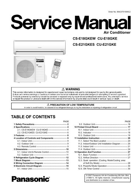
<strong>Air</strong> <strong>Conditioner</strong><br />
CS-E18GKEW CU-E18GKE<br />
CS-E21GKES CU-E21GKE<br />
PAGE PAGE<br />
9.2. Outdoor Unit----------------------------------------------- 16<br />
10 Printed Circuit Board ------------------------------------------ 17<br />
10.1. Indoor Unit ------------------------------------------------- 17<br />
10.2. Indicator ---------------------------------------------------- 18<br />
10.3. Outdoor Unit----------------------------------------------- 19<br />
11 Installation Instruction ---------------------------------------- 20<br />
11.1. Select The Best Location ------------------------------ 20<br />
11.2. Indoor/Outdoor Unit Installation Diagram ---------- 20<br />
11.3. Indoor Unit ------------------------------------------------- 21<br />
11.4. Outdoor Unit----------------------------------------------- 24<br />
12 Operation And Function-------------------------------------- 27<br />
12.1. Basic Function -------------------------------------------- 27<br />
12.2. <strong>Air</strong>flow Direction ------------------------------------------ 27<br />
12.3. Quiet operation (Cooling Mode/Cooling area<br />
of Soft Dry Mode) ---------------------------------------- 28<br />
12.4. Powerful Mode Operation------------------------------ 30<br />
12.5. ON Timer Control ---------------------------------------- 30<br />
© 2007 <strong>Panasonic</strong> HA <strong>Air</strong>-Conditioning (M) Sdn. Bhd.<br />
(11969-T). All rights reserved. Unauthorized copying<br />
and distribution is a violation of law.
12.6. OFF Timer Control --------------------------------------- 31<br />
12.7. Auto Restart Control------------------------------------- 31<br />
12.8. Indication Panel------------------------------------------- 31<br />
12.9. Patrol Operation ------------------------------------------ 31<br />
12.10. e-ion Operation ------------------------------------------- 33<br />
13 Protection Control ---------------------------------------------- 36<br />
13.1. Protection Control For All Operations--------------- 36<br />
13.2. Protection Control For Cooling & Soft Dry<br />
Operation--------------------------------------------------- 37<br />
13.3. Protection Control For Heating Operation --------- 38<br />
14 Servicing Mode -------------------------------------------------- 40<br />
14.1. Auto OFF/ON Button ------------------------------------ 40<br />
14.2. Select Remote Control Transmission Code ------- 40<br />
14.3. Remote Control Button --------------------------------- 41<br />
15 Troubleshooting Guide---------------------------------------- 42<br />
15.1. Refrigeration Cycle System --------------------------- 42<br />
1 Safety Precautions<br />
2<br />
15.2. Relationship Between The Condition Of The<br />
<strong>Air</strong> <strong>Conditioner</strong> And Pressure And Electric<br />
Current ----------------------------------------------------- 43<br />
15.3. Breakdown Self Diagnosis Function ---------------- 44<br />
15.4. Error Codes Table --------------------------------------- 45<br />
16 Disassembly and Assembly Instructions -------------- 46<br />
16.1. Indoor Electronic Controllers, Cross Flow Fan<br />
And Indoor Fan Motor Removal Procedures ----- 46<br />
16.2. Outdoor Electronic Controller Removal<br />
Procedure-------------------------------------------------- 50<br />
17 Technical Data --------------------------------------------------- 51<br />
17.1. Operation Characteristics ----------------------------- 51<br />
17.2. Sensible Capacity Chart ------------------------------- 59<br />
18 Exploded View and Replacement Parts List----------- 60<br />
18.1. CS-E18GKEW CS-E21GKES ----------------------- 60<br />
18.2. CU-E18GKE CU-E21GKE---------------------------- 62<br />
• Read the following “SAFETY PRECAUTIONS” carefully before perform any servicing.<br />
• Electrical work must be installed or serviced by a licensed electrician. Be sure to use the correct rating of the power plug and<br />
main circuit for the model installed.<br />
• The caution items stated here must be followed because these important contents are related to safety. The meaning of each<br />
indication used is as below.<br />
Incorrect installation or servicing due to ignoring of the instruction will cause harm or damage, and the seriousness is classified<br />
by the following indications.<br />
The items to be followed are classified by the symbols:<br />
This indication shows the possibility of causing death or serious injury.<br />
This indication shows the possibility of causing injury or damage to properties.<br />
This symbol denotes item that is PROHIBITED from doing.<br />
• Carry out test running to confirm that no abnormality occurs after the servicing. Then, explain to user the operation, care and<br />
maintenance as stated in instructions. Please remind the customer to keep the operating instructions for future reference.<br />
1. Engage dealer or specialist for installation and servicing. If installation or servicing done by the user is defective, it will cause water leakage,<br />
electrical shock or fire.<br />
2. Install according to this installation instructions strictly. If installation is defective, it will cause water leakage, electrical shock or fire.<br />
3. Use the attached accessories parts and specified parts for installation and servicing. Otherwise, it will cause the set to fall, water leakage,<br />
fire or electrical shock.<br />
4. Install at a strong and firm location which is able to withstand the set's weight. If the strength is not enough or installation is not properly<br />
done, the set will drop and cause injury.<br />
5. For electrical work, follow the local national wiring standard, regulation and the installation instruction. An independent circuit and single<br />
outlet must be used. If electrical circuit capacity is not enough or defect found in electrical work, it will cause electrical shock or fire.<br />
6. Use the specified cable and connect tightly for indoor/outdoor connection. Connect tightly and clamp the cable so that no external force will<br />
be acted on the terminal. If connection or fixing is not perfect, it will cause heat-up or fire at the connection.<br />
7. Wire routing must be properly arranged so that control board cover is fixed properly. If control board cover is not fixed perfectly, it will cause<br />
heat-up at connection point of terminal, fire or electrical shock.
8. When connecting the piping, do not allow air or any substances other than the specified refrigerant to enter the refrigeration<br />
cycle. Otherwise, this may lower the capacity, cause abnormally high pressure in the refrigeration cycle, and possibly result in<br />
explosion and injury.<br />
9. Thickness of copper pipes used must be more than 0.6 mm. Never use copper pipes thinner than 0.6 mm.<br />
10. It is desirable that the amount of residual oil is less than 40 mg/10 m.<br />
11. Do not modify the length of the power supply cord or use of the extension cord, and do not share the single outlet with other<br />
electrical appliances. Otherwise, it will cause fire or electrical shock.<br />
1. The equipment must be earthed. It may cause electrical shock if grounding is not perfect.<br />
2. Do not install the unit at place where leakage of flammable gas may occur. In case gas leaks and accumulates at surrounding<br />
of the unit, it may cause fire.<br />
3. Carry out drainage piping as mentioned in installation instructions. If drainage is not perfect, water may enter the room and damage the<br />
furniture.<br />
4. Pb free solder has a higher melting point than standard solder; typically the melting point is 50 - 70°F (30 - 40°C) higher. Please use a high<br />
temperature soldering iron. In case of the soldering iron with temperature control, please set it to 700 ± 20°F (370 ± 10°C).<br />
Pb free solder will tend to splash when heated too high (about 1100°F/600°C).<br />
1. Selection of the installation location. Select an installation location which is rigid and strong enough to support or hold the unit, and select a<br />
location for easy maintenance.<br />
2. Power supply connection to the conditioner. Connect the power supply cord of the air conditioner to the mains using one of the following<br />
methods. Power supply point shall be the place where there is ease for access for the power disconnection in case of emergency.<br />
In some countries, permanent connection of this room air conditioner to the power supply is prohibited.<br />
1. Power supply connection to the receptacle using a power plug. Use an approved power plug with earth pin for the connection to the<br />
socket.<br />
2. Power supply connection to a circuit breaker for the permanent connection. Use an approved circuit breaker for the permanent<br />
connection. It must be a double pole switch with a minimum 3.5 mm contact gap.<br />
3. Do not release refrigerant during piping work for installation, servicing reinstallation and during repairing a refrigeration parts. Take care of<br />
the liquid refrigerant, it may cause frostbite.<br />
4. Installation work. It may need two people to carry out the installation work.<br />
5. Do not install this appliance in a laundry room or other location where water may drip from the ceiling, etc.<br />
3
2 Specifications<br />
2.1. CS-E18GKEW CU-E18GKE<br />
ITEM UNIT INDOOR UNIT OUTDOOR UNIT<br />
Performance Test Condition EUROVENT<br />
C<br />
O<br />
O<br />
L<br />
I<br />
N<br />
G<br />
H<br />
E<br />
A<br />
T<br />
I<br />
N<br />
G<br />
Capacity<br />
EER<br />
Noise Level<br />
Capacity<br />
COP<br />
Noise Level<br />
Moisture Removal<br />
<strong>Air</strong> Volume<br />
Lo m 3 /min (ft 3 /min)<br />
Me m 3 /min (ft 3 /min)<br />
kW 5.30 (0.90 ~ 6.00)<br />
BTU/h 18100 (3070 ~ 20500)<br />
kCal/h 4560 (770 ~ 5160)<br />
W/W 3.21 (4.19 ~ 2.93)<br />
BTU/hW 11.0 (14.3 ~ 10.0)<br />
dB (A) High 44, Low 37 High 47<br />
Power level dB 57 60<br />
kW 6.60 (0.90 ~ 8.00)<br />
BTU/h 22500 (3070 ~ 27300)<br />
kCal/h 5680 (770 ~ 6880)<br />
W/W 3.69 (3.67 ~ 3.02)<br />
BTU/hW 12.6 (12.5 ~ 10.3)<br />
dB (A) High 44, Low 37 High 47<br />
Power level dB 57 60<br />
l/h 2.9<br />
pt/h 6.1<br />
4<br />
Cooling; 12.3 (430)<br />
Heating; 13.0 (460)<br />
Cooling; 13.9 (490)<br />
Heating; 14.6 (520)<br />
Hi m3 /min (ft3 /min)<br />
Cooling; 15.2 (540)<br />
Heating; 16.7 (590)<br />
Cooling; 40.0 (1410)<br />
Heating; 40.0 (1410)<br />
Refrigeration Control Device — Expansion Valve<br />
Refrigeration Oil cm 3 — RB68A or Freol Alpha68M (400)<br />
Refrigerant (R410A) g (oz) — 1.18k (41.7)<br />
Height mm (inch) 275 (10-13/16) 750 (29-17/32)<br />
Dimension<br />
Width mm (inch) 998 (39-9/32) 875 (34-7/16)<br />
Depth mm (inch) 230 (9-1/16) 345 (13-19/32)<br />
Net Weight kg (lbs) 10 (22) 48 (106)<br />
Pipe Diameter<br />
Gas<br />
Liquid<br />
mm (inch)<br />
mm (inch)<br />
12.7 (1/2)<br />
6.35 (1/4)<br />
Standard Length m (ft) 5.0 (16.4)<br />
Pipe Length Range m (ft) 3 (9.8) ~ 20 (65.6)<br />
Height Difference m (ft) 15 (49.2)<br />
Additional Gas Amount g/m (oz/ft) 20 (0.2)<br />
Refrigeration Charge Less m (ft) 10 (32.8)<br />
Drain Hose<br />
Compressor<br />
Fan<br />
Inner Diameter mm 12 —<br />
Length mm 650 —<br />
Type — Hermetic Motor<br />
Motor Type — Brushless (4-pole)<br />
Rated Output W — 900<br />
Type Cross-Flow Fan Propeller Fan<br />
Material ASHT-18 PP<br />
Motor Type Transistor (8-pole) Transistor (8-pole)<br />
Output Power W 30 40<br />
Fan Speed<br />
Lo (Cool/Heat) rpm 1170 / 1240 —<br />
Me (Cool/Heat) rpm 1330 / 1395 —<br />
Hi (Cool/Heat) rpm 1450 / 1580 660 / 640<br />
—<br />
—
Heat Exchanger<br />
<strong>Air</strong> Filter<br />
ITEM UNIT INDOOR UNIT OUTDOOR UNIT<br />
Fin Material Aluminium (Pre Coat) Aluminium<br />
Fin Type Slit Fin Corrugated Fin<br />
Row x Stage x FPI 2 x 15 x 19 2 x 34 x 16<br />
Size (W x H x L) mm 810 x 315 x 25.4<br />
1. Cooling capacities are based on indoor temperature of 27°C D.B. (80.6°F D.B.), 19.0°C W.B. (66.2°F W.B.) and outdoor air<br />
temperature of 35°C D.B. (95°F D.B.), 24°C W.B. (75.2°F W.B.)<br />
2. Heating capacities are based on indoor temperature of 20°C D.B. (68°F D.B.) and outdoor air temperature of 7°C D.B. (44.6°F<br />
D.B.), 6°C W.B. (42.8°F W.B.)<br />
Note<br />
• Specifications are subject to change without notice for further improvement.<br />
5<br />
36.4 x 714 x 803<br />
831<br />
Material Polypropelene —<br />
Type One-Touch —<br />
Item Unit<br />
ø Single<br />
Power Source (Phase, Voltage, Cycle)<br />
V 230<br />
Hz 50<br />
Cooling; 1.65k (215 ~ 2.05k)<br />
Input Power W<br />
Heating; 1.79k (245 ~ 2.65k)<br />
Starting Current A 8.3<br />
Cooling; 7.5<br />
Running Current A<br />
Heating; 8.1<br />
Cooling; 96<br />
Power Factor %<br />
Heating; 96<br />
Power factor means total figure of compressor, indoor fan motor and outdoor fan motor.<br />
*Maximum over current protection A 11.9<br />
Power Cord<br />
Number of core<br />
Length m<br />
—<br />
—<br />
Thermostat Electronic Control<br />
Protection Device Electronic Control
2.2. CS-E21GKES CU-E21GKE<br />
ITEM UNIT INDOOR UNIT OUTDOOR UNIT<br />
Performance Test Condition EUROVENT<br />
C<br />
O<br />
O<br />
L<br />
I<br />
N<br />
G<br />
H<br />
E<br />
A<br />
T<br />
I<br />
N<br />
G<br />
Capacity<br />
EER<br />
Noise Level<br />
Capacity<br />
COP<br />
Noise Level<br />
Moisture Removal<br />
<strong>Air</strong> Volume<br />
Lo m 3 /min (ft 3 /min)<br />
Me m 3 /min (ft 3 /min)<br />
kW 6.30 (0.90 ~ 7.10)<br />
BTU/h 21500 (3070 ~ 24200)<br />
kCal/h 5420 (770 ~ 6110)<br />
W/W 2.85 (4.19 ~ 2.80)<br />
BTU/hW 9.7 (14.3 ~ 9.5)<br />
dB (A) High 45, Low 37 High 48<br />
Power level dB 58 61<br />
kW 7.20 (0.90 ~ 8.50)<br />
BTU/h 24600 (3070 ~ 29000)<br />
kCal/h 6190 (770 ~ 7310)<br />
W/W 3.43 (3.67 ~ 3.09)<br />
BTU/hW 11.7 (12.5 ~ 10.5)<br />
dB (A) High 45, Low 37 High 49<br />
Power level dB 58 62<br />
l/h 3.5<br />
pt/h 7.4<br />
6<br />
Cooling; 12.5 (440)<br />
Heating; 13.5 (480)<br />
Cooling; 14.4 (510)<br />
Heating; 14.9 (530)<br />
Hi m 3 /min (ft 3 /min)<br />
Cooling; 16.2 (570)<br />
Heating; 17.3 (610)<br />
Cooling; 42.8 (1510)<br />
Heating; 41.5 (1460)<br />
Refrigeration Control Device — Expansion Valve<br />
Refrigeration Oil cm3 — RB68A or Freol Alpha68M (400)<br />
Refrigerant (R410A) g (oz) — 1.29k (45.5)<br />
Height mm (inch) 275 (10-13/16) 750 (29-17/32)<br />
Dimension<br />
Width mm (inch) 998 (39-9/32) 875 (34-7/16)<br />
Depth mm (inch) 230 (9-1/16) 345 (13-19/32)<br />
Net Weight kg (lbs) 10 (22) 49 (108)<br />
Pipe Diameter<br />
Gas<br />
Liquid<br />
mm (inch)<br />
mm (inch)<br />
12.7 (1/2)<br />
6.35 (1/4)<br />
Standard Length m (ft) 5.0 (16.4)<br />
Pipe Length Range m (ft) 3 (9.8) ~ 20 (65.6)<br />
Height Difference m (ft) 15 (49.2)<br />
Additional Gas Amount g/m (oz/ft) 20 (0.2)<br />
Refrigeration Charge Less m (ft) 10 (32.8)<br />
Drain Hose<br />
Compressor<br />
Fan<br />
Inner Diameter mm 12 —<br />
Length mm 650 —<br />
Type — Hermetic Motor<br />
Motor Type — Brushless (4-pole)<br />
Rated Output W — 900<br />
Type Cross-Flow Fan Propeller Fan<br />
Material ASHT-18 PP<br />
Motor Type Transistor (8-pole) Transistor (8-pole)<br />
Output Power W 30 40<br />
Fan Speed<br />
Lo (Cool/Heat) rpm 1170 / 1270 —<br />
Me (Cool/Heat) rpm 1355 / 1400 —<br />
Hi (Cool/Heat) rpm 1520 / 1610 700 / 680<br />
—<br />
—
Heat Exchanger<br />
<strong>Air</strong> Filter<br />
ITEM UNIT INDOOR UNIT OUTDOOR UNIT<br />
Fin Material Aluminium (Pre Coat) Aluminium<br />
Fin Type Slit Fin Corrugated Fin<br />
Row x Stage x FPI 2 x 15 x 19 2 x 34 x 18<br />
Size (W x H x L) mm 810 x 315 x 25.4<br />
1. Cooling capacities are based on indoor temperature of 27°C D.B. (80.6°F D.B.), 19.0°C W.B. (66.2°F W.B.) and outdoor air<br />
temperature of 35°C D.B. (95°F D.B.), 24°C W.B. (75.2°F W.B.)<br />
2. Heating capacities are based on indoor temperature of 20°C D.B. (68°F D.B.) and outdoor air temperature of 7°C D.B. (44.6°F<br />
D.B.), 6°C W.B. (42.8°F W.B.)<br />
Note<br />
• Specifications are subject to change without notice for further improvement.<br />
7<br />
36.4 x 714 x 803<br />
831<br />
Material Polypropelene —<br />
Type One-Touch —<br />
Item Unit<br />
ø Single<br />
Power Source (Phase, Voltage, Cycle)<br />
V 230<br />
Hz 50<br />
Cooling; 2.21k (215 ~ 2.54k)<br />
Input Power W<br />
Heating; 2.10k (245 ~ 2.75k)<br />
Starting Current A 9.7<br />
Cooling; 9.9<br />
Running Current A<br />
Heating; 9.3<br />
Cooling; 97<br />
Power Factor %<br />
Heating; 98<br />
Power factor means total figure of compressor, indoor fan motor and outdoor fan motor.<br />
*Maximum over current protection A 12.6<br />
Power Cord<br />
Number of core<br />
Length m<br />
—<br />
—<br />
Thermostat Electronic Control<br />
Protection Device Electronic Control
3 Features<br />
• Product<br />
- Four modes of operation selection<br />
- Powerful mode to reach the desired room temperature<br />
quickly with full power and a strong airflow<br />
- Quiet mode to provide a quiet environment by reducing<br />
the indoor unit operating airflow sound<br />
- 24-hour ON Timer and OFF Timer setting<br />
- <strong>Air</strong> swing manual and automatic adjusted by Remote<br />
Control for vertical and horizontal airflow.<br />
- Patrol sensor automatically detect the air quality. When<br />
the air quality is unsatisfactory, e-ion operation will start<br />
automatically.<br />
- e-ion <strong>Air</strong> Purifying System provides clean air by<br />
producing negative ions to attract dust which will then be<br />
captured at the positively charged e-ion filters.<br />
8<br />
• Serviceability Improvement<br />
- Removable and washable Front Panel<br />
- Breakdown Self Diagnosis function<br />
• Environmental Protection<br />
- Non-ozone depletion substances refrigerant (R410A)<br />
• Operation Improvement<br />
- Random auto restart control after power failure for safety<br />
restart operation<br />
- Advanced inverter technology provides outstanding<br />
energy efficiency and powerful, flexible, comfortable<br />
operation
4 Location of Controls and Components<br />
4.1. Indoor Unit<br />
4.2. Outdoor Unit<br />
4.3. Remote Control<br />
9
5 Dimensions<br />
5.1. Indoor Unit & Remote Control<br />
10
5.2. Outdoor Unit<br />
11
6 Refrigeration Cycle Diagram<br />
Piping size Rated Common Max. Min. Piping Max. Piping Additional<br />
Model<br />
Gas Liquid<br />
Length<br />
(m)<br />
Length<br />
(m)<br />
Elevation<br />
(m)<br />
Length<br />
(m)<br />
Length<br />
(m)<br />
Refrigerant<br />
(g/m)<br />
E18GK, E21GK 1/2” 1/4” 5 10 15 3 20 20<br />
If piping length is over common length, additional refrigerant should be added as shown in the table.<br />
12
7 Block Diagram<br />
13
8 Wiring Connection Diagram<br />
14
9 Electronic Circuit Diagram<br />
9.1. Indoor Unit<br />
15
9.2. Outdoor Unit<br />
16
10 Printed Circuit Board<br />
10.1. Indoor Unit<br />
10.1.1. Main Printed Circuit Board<br />
17
10.1.2. Power Printed Circuit Board<br />
10.2. Indicator<br />
18
10.3. Outdoor Unit<br />
19
11 Installation Instruction<br />
11.1. Select The Best Location<br />
INDOOR UNIT<br />
• There should not be any heat source or steam near the unit.<br />
• There should not be any obstacles blocking the air<br />
circulation.<br />
• A place where air circulation in the room is good.<br />
• A place where drainage can be easily done.<br />
• A place where noise prevention is taken into consideration.<br />
• Do not install the unit near the door way.<br />
• Ensure the spaces indicated by arrows from the wall, ceiling,<br />
fence or other obstacles.<br />
• Recommended installation height for indoor unit shall be at<br />
least 2.5 m.<br />
OUTDOOR UNIT<br />
• If an awning is built over the unit to prevent direct sunlight or<br />
rain, be careful that heat radiation from the condenser is not<br />
obstructed.<br />
• There should not be any animal or plant which could be<br />
affected by hot air discharged.<br />
• Keep the spaces indicated by arrows from wall, ceiling,<br />
fence or other obstacles.<br />
• Do not place any obstacles which may cause a short circuit<br />
of the discharged air.<br />
• If piping length is over 10 m, additional refrigerant should be<br />
added as shown in the table.<br />
Model<br />
Piping size Rated<br />
Gas Liquid<br />
Length<br />
(m)<br />
Max<br />
Elevation<br />
(m)<br />
Min.<br />
Piping<br />
Length<br />
(m)<br />
Max.<br />
Piping<br />
Length<br />
(m)<br />
Additional<br />
Refrigerant<br />
(g/m)<br />
E18GK 1/2” 1/4” 5 15 3 20 20<br />
E21GK 1/2” 1/4” 5 15 3 20 20<br />
Example : For E18GK<br />
If the unit is installed at a 15 m distance, the quantity of<br />
additional refrigerant should be 100 g ...... (15 - 10) m x 20 g/m<br />
= 100 g.<br />
20<br />
11.2. Indoor/Outdoor Unit<br />
Installation Diagram
11.3. Indoor Unit<br />
11.3.1. HOW TO FIX INSTALLATION PLATE<br />
The mounting wall is strong and solid enough to prevent it from<br />
the vibration.<br />
The centre of installation plate should be at more than 550 mm<br />
at right and left of the wall.<br />
The distance from installation plate edge to ceiling should more<br />
than 67 mm.<br />
From installation plate left edge to unit’s left side is 47 mm.<br />
From installation plate right edge to unit’s right is 73 mm.<br />
: For left side piping, piping connection for liquid should be about<br />
126 mm from this line.<br />
: For left side piping, piping connection for gas should be about<br />
174 mm from this line.<br />
: For left side piping, piping connection cable should be about<br />
984 mm from this line.<br />
1. Mount the installation plate on the wall with 5 screws or<br />
more.<br />
(If mounting the unit on the concrete wall consider using<br />
anchor bolts.)<br />
• Always mount the installation plate horizontally by<br />
aligning the marking-off line with the thread and using a<br />
level gauge.<br />
2. Drill the piping plate hole with ø70 mm hole-core drill.<br />
• Line according to the left and right side of the installation<br />
plate. The meeting point of the extended line is the<br />
centre of the hole. Another method is by putting<br />
measuring tape at position as shown in the diagram<br />
above. The hole centre is obtained by measuring the<br />
distance namely 150 mm and 125 mm for left and right<br />
hole respectively.<br />
• Drill the piping hole at either the right or the left and the<br />
hole should be slightly slanted to the outdoor side.<br />
21<br />
11.3.2. TO DRILL A HOLE IN THE WALL<br />
AND INSTALL A SLEEVE OF<br />
PIPING<br />
1. Insert the piping sleeve to the hole.<br />
2. Fix the bushing to the sleeve.<br />
3. Cut the sleeve until it extrudes about 15 mm from the<br />
wall.<br />
Caution<br />
When the wall is hollow, please be sure to use the<br />
sleeve for tube ass’y to prevent dangers caused by<br />
mice biting the connecting cable.<br />
4. Finish by sealing the sleeve with putty or caulking<br />
compound at the final stage.<br />
11.3.3. INDOOR UNIT INSTALLATION<br />
1. For the right rear piping<br />
2. For the right and right bottom piping
3. For the embedded piping<br />
22<br />
(This can be used for left rear piping & left bottom piping also.)
23<br />
11.3.4. CONNECT THE CABLE TO THE<br />
INDOOR UNIT<br />
1. The inside and outside connecting cable can be<br />
connected without removing the front grille.<br />
2. Connecting cable between indoor unit and outdoor unit<br />
shall be approved polychloroprene sheathed 4 × 1.5 mm 2<br />
flexible cord, type designation 245 IEC 57 or heavier<br />
cord.<br />
• Ensure the colour of wires of outdoor unit and the<br />
terminal Nos. are the same to the indoor’s respectively.<br />
• Earth lead wire shall be longer than the other lead wires<br />
as shown in the figure for the electrical safety in case of<br />
the slipping out of the cord from the anchorage.<br />
• Secure the cable onto the control board with the holder<br />
(clamper).
11.4. Outdoor Unit<br />
11.4.1. INSTALL THE OUTDOOR UNIT<br />
• After selecting the best location, start installation according<br />
to Indoor/Outdoor Unit Installation Diagram.<br />
1. Fix the unit on concrete or rigid frame firmly and<br />
horizontally by bolt nut (ø10 mm).<br />
2. When installing at roof, please consider strong wind and<br />
earthquake. Please fasten the installation stand firmly<br />
with bolt or nails.<br />
11.4.2. CONNECTING THE PIPING<br />
Connecting The Piping To Indoor Unit<br />
Please make flare after inserting flare nut (locate at joint portion of tube assembly) onto the copper pipe.<br />
(in case of using long piping).<br />
Connect the piping<br />
• Align the center of piping and sufficiently tighten the flare nut with fingers.<br />
• Further tighten the flare nut with torque wrench in specified torque as stated in the table.<br />
Connecting The Piping To Outdoor Unit<br />
Decide piping length and then cut by using pipe cutter. Remove burrs from cut edge. Make flare after inserting the flare nut<br />
(locate at valve) onto the copper pipe.<br />
Align center of piping to valves and then tighten with torque wrench to the specified torque as stated in the table.<br />
CUTTING AND FLARING THE PIPING<br />
1. Please cut using pipe cutter and then remove the burrs.<br />
2. Remove the burrs by using reamer. If burrs is not removed, gas leakage may be caused.<br />
Turn the piping end down to avoid the metal powder entering the pipe.<br />
3. Please make flare after inserting the flare nut onto the copper pipes.<br />
24<br />
Model Piping size (Torque)<br />
Gas Liquid<br />
E18GK, E21GK 1/2” [55 N�m] 1/4” [18 N�m)
11.4.3. EVACUATION OF THE EQUIPMENT<br />
WHEN INSTALLING AN AIR CONDITIONER, BE SURE TO EVACUATE THE AIR INSIDE THE INDOOR UNIT AND PIPES in the<br />
following procedure.<br />
1. Connect a charging hose with a push pin to the Low side of a charging set and the service port of the 3-way valve.<br />
• Be sure to connect the end of the charging hose with the push pin to the service port.<br />
2. Connect the center hose of the charging set to a vacuum pump with check valve, or vacuum pump and vacuum pump<br />
adaptor.<br />
3. Turn on the power switch of the vacuum pump and make sure that the needle in the gauge moves from 0 cmHg (0 MPa) to<br />
-76 cmHg (-0.1 MPa). Then evacuate the air approximately ten minutes.<br />
4. Close the Low side valve of the charging set and turn off the vacuum pump. Make sure that the needle in the gauge does not<br />
move after approximately five minutes.<br />
Note: BE SURE TO FOLLOW THIS PROCEDURE IN ORDER TO AVOID REFRIGERANT GAS LEAKAGE.<br />
5. Disconnect the charging hose from the vacuum pump and from the service port of the 3-way valve.<br />
6. Tighten the service port caps of the 3-way valve at torque of 18 N �m with a torque wrench.<br />
7. Remove the valve caps of both of the 2-way valve and 3-way valve. Position both of the valves to “OPEN” using a hexagonal<br />
wrench (4 mm).<br />
8. Mount valve caps onto the 2-way valve and the 3-way valve.<br />
• Be sure to check for gas leakage.<br />
CAUTION<br />
• If gauge needle does not move from 0 cmHg (0 MPa) to -76 cmHg (-0.1 MPa), in step above take the following measure:<br />
• If the leak stops when the piping connections are tightened further, continue working from step .<br />
• If the leak does not stop when the connections are retightened, repair the location of leak.<br />
• Do not release refrigerant during piping work for installation and reinstallation. Take care of the liquid refrigerant, it may cause frostbite.<br />
25
11.4.4. CONNECT THE CABLE TO THE OUTDOOR UNIT<br />
(FOR DETAIL REFER TO WIRING DIAGRAM AT UNIT)<br />
1. Remove the control board cover from the unit by loosening the screw.<br />
2. Connecting cable between indoor unit and outdoor unit shall be approved polychloroprene sheathed 4 x 1.5 mm 2 flexible<br />
cord, type designation 245 IEC 57 or heavier cord.<br />
3. Secure the cable onto the control board with the holder (clamper).<br />
4. Cable connection to the power supply through knife switch (Disconnecting means).<br />
• Connect the approved polychloroprene sheathed power supply cable (3 x 1.5 mm2 ), type designation 245 IEC 57 or heavier<br />
cord to the terminal board, and connect the other end of the cable to knife switch (Disconnecting means).<br />
Note : Knife switch (Disconnecting means) should have minimum 3.5 mm contact gap.<br />
• Secure the cable onto the control board with the holder (clamper).<br />
26
12 Operation And Function<br />
12.1. Basic Function<br />
Inverter control, which equipped with a microcomputer in determining the most suitable operating mode as time passes,<br />
automatically adjusts output power for maximum comfort always. In order to achieve the suitable operating mode, the<br />
microcomputer maintains the set temperature by measuring the temperature of the environment and performing temperature<br />
shifting. The compressor at outdoor unit is operating following the frequency instructed by the microcomputer at indoor unit that<br />
judging the condition according to internal setting temperature and intake air temperature.<br />
12.1.1. Internal Setting Temperature<br />
Once the operation starts, remote control setting temperature will be taken as base value for temperature shifting processes.<br />
These shifting processes are depending on the air conditioner settings and the operation environment. The final shifted value<br />
will be used as internal setting temperature and it is updated continuously whenever the electrical power is supplied to the unit.<br />
12.2. <strong>Air</strong>flow Direction<br />
1. There are two types of airflow, vertical airflow (directed by horizontal vane) and horizontal airflow (directed by vertical vanes).<br />
2. Control of airflow direction can be automatic (angles of direction is determined by operation mode, heat exchanger<br />
temperature and intake air temperature) and manual (angles of direction can be adjusted using remote control).<br />
Vertical <strong>Air</strong>flow<br />
Operation Mode <strong>Air</strong>flow Direction<br />
1<br />
Vane Angle (°)<br />
2 3 4 5<br />
Heating Auto with Heat Exchanger A 16<br />
B 50<br />
Temperature C 8<br />
D 8<br />
Manual 8 17 33 49 60<br />
Cooling and Soft Dry Auto 8 ~ 38<br />
Manual 8 17 25 33 38<br />
Mode Judgment in Auto Auto 8<br />
Manual 8 17 25 33 38<br />
27
1. Automatic vertical airflow direction can be set using remote control; the vane swings up and down within the angles as stated<br />
above. For heating mode operation, the angle of the vane depends on the indoor heat exchanger temperature as Figure 1<br />
below. When the air conditioner is stopped using remote control, the vane will shift to close position.<br />
2. Manual vertical airflow direction can be set using remote control; the angles of the vane are as stated above and the positions<br />
of the vane are as Figure 2 below. When the air conditioner is stopped using remote control, the vane will shift to close<br />
position.<br />
Horizontal <strong>Air</strong>flow<br />
1. Automatic horizontal airflow direction can be set using remote control; the vane swings left and right within the angles as<br />
stated below. For heating mode operation, the angle of the vane depends on the indoor heat exchanger temperature as<br />
Figure 1 below.<br />
2. Manual horizontal airflow direction can be set using remote control; the angles of the vane are as stated below and the<br />
positions of the vane are as Figure 2 above.<br />
12.3. Quiet operation (Cooling Mode/Cooling area of Soft Dry Mode)<br />
A. Purpose<br />
To provide quiet cooling operation compare to normal operation.<br />
B. Control condition<br />
a. Quiet operation start condition<br />
• When “quiet” button at remote control is pressed.<br />
Quiet LED illuminates.<br />
b. Quiet operation stop condition<br />
Operation Mode Vane Angle (°)<br />
Heating, with heat exchanger temperature<br />
A<br />
B<br />
68 ~ 112<br />
90<br />
Cooling and Soft Dry 68 ~ 112<br />
Pattern<br />
<strong>Air</strong>flow Direction<br />
Patterns at Remote<br />
Control<br />
1 2 3 4 5<br />
Vane Angle (°) 90 68 79 101 112<br />
28
1. When one of the following conditions is satisfied, quiet operation stops:<br />
a. Powerful button is pressed.<br />
b. Stop by OFF/ON switch.<br />
c. Timer “off” activates.<br />
d. Quiet button is pressed again.<br />
2. When quiet operation is stopped, operation is shifted to normal operation with previous setting.<br />
3. When fan speed is changed, quiet operation is shifted to quiet operation of the new fan speed.<br />
4. When operation mode is changed, quiet operation is shifted to quiet operation of the new mode.<br />
5. During quiet operation, if timer “on” activates, quiet operation maintains.<br />
6. After off, when on back, quiet operation is not memorised.<br />
C. Control contents<br />
1. Fan speed is changed from normal setting to quiet setting of respective fan speed.<br />
This is to reduce sound of Hi, Me, Lo for 3dB.<br />
2. Fan speed for quiet operation is -100 rpm from setting fan speed.<br />
12.3.1. Quiet operation under Soft Dry operation (Dry area at Soft Dry Mode)<br />
Automatic Fan Speed (Soft dry operation)<br />
Manual Fan Speed (Soft dry operation)<br />
12.3.2. Quiet operation (Heating)<br />
A. Purpose<br />
To provide quiet heating operation compare to normal operation.<br />
B. Control condition<br />
a. Quiet operation start condition<br />
• When “quiet” button at remote control is pressed.<br />
Quiet LED illuminates.<br />
b. Quiet operation stop condition<br />
1. When one of the following conditions is satisfied, quiet operation stops:<br />
a. Powerful button is pressed.<br />
b. Stop by OFF/ON switch.<br />
c. Timer “off” activates.<br />
d. Quiet button is pressed again.<br />
2. When quiet operation is stopped, operation is shifted to normal operation with previous setting.<br />
3. When fan speed is changed, quiet operation is shifted to quiet operation of the new fan speed.<br />
4. When operation mode is changed, quiet operation is shifted to quiet operation of the new mode, except fan only mode.<br />
5. During quiet operation, if timer “on” activates, quiet operation maintains.<br />
6. After off, when on back, quiet operation is not memorised.<br />
29
C. Control contents<br />
a. Fan Speed manual<br />
1. Fan speed is changed from normal setting to quiet setting of respective fan speed.<br />
This is to reduce sound of Hi, Me, Lo for 3dB.<br />
2. Fan speed for quiet operation is -100 rpm from setting fan speed.<br />
3. Fan Speed Auto<br />
• If FM Lo<br />
-100 rpm reduce from normal Heating Auto Fan Speed<br />
• If FM Lo<br />
maintain RPM<br />
Indoor FM RPM depends on pipe temp sensor of indoor heat exchanger.<br />
12.4. Powerful Mode Operation<br />
When the powerful mode is selected, the internal setting temperature will shift to achieve the setting temperature quickly.<br />
(a) Cooling Operation<br />
(b) Soft Dry Operation<br />
(c) Heating Operation<br />
12.5. ON Timer Control<br />
ON timer can be set using remote control, the unit with timer set will start operate earlier than the setting time. This is to provide a<br />
comfortable environment when reaching the set ON time.<br />
Seventy minutes before the set time, indoor (at fan speed of Lo-) and outdoor fan motor start operate for 30 seconds to determine<br />
the indoor intake air temperature and outdoor air temperature in order to judge the operation starting time.<br />
From the above judgment, the decided operation will start operate earlier than the set time as shown below.<br />
30
12.6. OFF Timer Control<br />
OFF timer can be set using remote control, the unit with timer set will stop operate at set time.<br />
12.7. Auto Restart Control<br />
1. When the power supply is cut off during the operation of air conditioner, the compressor will re-operate within three to four<br />
minutes (there are 10 patterns between 2 minutes 58 seconds and 3 minutes 52 seconds to be selected randomly) after<br />
power supply resumes.<br />
2. This type of control is not applicable during ON/OFF Timer setting.<br />
12.8. Indication Panel<br />
LED POWER TIMER QUIET POWERFUL e-ion PATROL SENSOR<br />
Color Green Orange Orange Orange Blue Blue<br />
Light ON Operation ON Quiet Setting ON Quiet Mode ON Powerful Mode ON e-ion ON PATROL ON<br />
Light OFF Operation OFF Quiet Setting OFF Quiet Mode OFF Powerful Mode OFF e-ion OFF PATROL OFF<br />
Note:<br />
• If POWER LED is blinking, the possible operation of the unit are Hot Start, during Deice operation, operation mode judgment, or<br />
ON timer sampling.<br />
• If Timer LED is blinking, there is an abnormality operation occurs.<br />
• If e-ion LED is blinking, there is an abnormality of e-ion occurs.<br />
• If PATROL LED is blinking, there is a gas sensor error detection.<br />
12.9. Patrol Operation<br />
A. Purpose<br />
To monitor air dirtiness level by using gas sensor and activates e-ion operation whenever air is dirty.<br />
B. Control Condition<br />
a. Patrol operation start condition<br />
• When the unit operation is started with “OFF/ON” button.<br />
• When the unit stops, “Patrol” button is pressed, Patrol individual operation will start.<br />
• During cooling only operation, “Patrol” button is pressed.<br />
31
. Patrol operation stop condition<br />
When any of the following condition is fulfilled:<br />
• When “OFF/ON” button is pressed.<br />
• During any operation with Patrol, “Patrol” button is pressed again.<br />
• When “e-ion” button is pressed.<br />
• When OFF Timer activates.<br />
c. Patrol operation disable<br />
• To disable the Patrol Operation during unit start (default) with “OFF/ON” button, press “Patrol” button and hold for 5 seconds,<br />
then release.<br />
• To disable the Patrol Operation, press “Patrol” button and hold for 15 seconds, then release.<br />
C. Control Content<br />
a. Gas Sensor Control<br />
• First 2 minutes from Patrol function activates is stabilization time, during stabilization time, no air dirtiness level is monitored.<br />
The <strong>Air</strong> Dirtiness level is set to level 2.<br />
• After that, gas sensor starts to record the resistance value at fixed interval. Higher resistance value indicates cleaner air.<br />
• The air dirtiness level is monitored by comparing the current resistance value with maximum resistance value from time to time<br />
to get the <strong>Air</strong> Dirtiness Value.<br />
• There are 3 air dirtiness levels, based on the <strong>Air</strong> Dirtiness Value:<br />
- <strong>Air</strong> Dirtiness level 0: Clean<br />
- <strong>Air</strong> Dirtiness level 1: Moderate<br />
- <strong>Air</strong> Dirtiness level 2: Contaminated<br />
• Dirtiness level sensitivity adjustment<br />
It is possible to change the gas sensor sensitivity, where the Threshold value (G1 ~ G4) will be shifted accordingly:<br />
1. Press and release “SET” buttton.<br />
2. Press “Timer increment” / “Timer decrement” button to select sensitivity. (Low Standard (Default) High)<br />
3. Confirm setting by pressing “Timer Set” button. LCD returned to original display after 2 seconds.<br />
4. LCD returned to original display if remote control does not operate for 30 seconds.<br />
b. e-ion Control<br />
• When dirtiness level is 1 or 2, e-ion operation starts.<br />
• If dirtiness level improves from level 2 to level 1, the unit carries out level change after 60 seconds.<br />
• When dirtiness level returns to level 0 continuously for 10 minutes or more, e-ion operation stops.<br />
Dirtiness Level Shift<br />
• For Auto Fan Speed, the fan speed increased based on dirtiness level:<br />
c. Indoor Fan Control<br />
• During any operation mode combines with Patrol operation, fan speed follows respective operation mode.<br />
• During Patrol individual operation if e-ion starts, only Auto Fan Speed and no Powerful operation is allowed. Even if “Fan<br />
Speed” button is pressed, no signal is sent to air conditioner, and no change on LCD display.<br />
• During Patrol individual operation if e-ion stops, Indoor Fan stop operation.<br />
32
d. <strong>Air</strong>flow direction (Horizontal, Vertical) Control<br />
• During any operation mode combines with Patrol operation, airflow direction follows respective operation mode.<br />
• During Patrol individual operation if e-ion starts, only Auto <strong>Air</strong> Swing is allowed. Even if “<strong>Air</strong> Swing” button is pressed, no signal<br />
is sent to air conditioner, and no change on LCD display.<br />
• During Patrol individual operation if e-ion stops, <strong>Air</strong>flow direction louver closed.<br />
e. Indicator<br />
• When Patrol operation starts, Patrol Sensor indicator ON.<br />
• When e-ion operation starts based on dirtiness level, e-ion indicator ON.<br />
f. Remote Control Receiving Sound<br />
• Normal Operation<br />
• Patrol Mode<br />
• Patrol Mode<br />
• Stop<br />
→<br />
→<br />
→<br />
→<br />
Patrol Mode<br />
Stop<br />
Normal Operation<br />
Patrol<br />
g. Timer Control<br />
• When ON timer activates when unit stops, previous operation resumes without Patrol operation.<br />
• When ON timer activates during any operation, no change and carry on current operation.<br />
• When OFF timer activates during any operation, all operation stops.<br />
h. Power failure<br />
• During Patrol individual operation, if power failure occurs, after power resumes, Patrol individual operation resumes<br />
immediately.<br />
• During combination operation, if power failure occurs, after power resumes combination operation resume immediately.<br />
12.10. e-ion Operation<br />
A. Purpose<br />
This operation provides clean air by producing negative ions to attract dust captured at the positively charged e-ion filters.<br />
B. Control Condition<br />
a. e-ion operation start condition<br />
• During unit running at any operation mode, if “e-ion” button is pressed, combination operation (operation mode + e-ion<br />
operation) starts.<br />
• During unit is OFF, if “e-ion” button is pressed, e-ion individual operation starts.<br />
b. e-ion operation stop condition<br />
• When “OFF/ON” button is pressed to stop the operation.<br />
• When “e-ion” button is pressed again.<br />
• When “Patrol” button is pressed.<br />
• When OFF Timer activates.<br />
:<br />
:<br />
:<br />
:<br />
Beep<br />
Long Beep<br />
Beep<br />
Beep<br />
33
c. e-ion operation pause condition<br />
• When indoor fan stop (during deice, odor cut control, thermostat off, etc.). e-ion operation resume after indoor fan restarts.<br />
• When indoor intake temperature 40°C. e-ion operation resume after indoor intake temperature < 40°C continuously for 30<br />
minutes.<br />
C. Control Content<br />
a. Indoor fan control<br />
• During any operation mode combines with e-ion operation, fan speed follows respective operation mode.<br />
• During e-ion individual operation - only Auto Fan Speed and no Powerful operation is allowed. Even if Fan Speed button is<br />
pressed, no signal is sent to air conditioner, and no change on LCD display.<br />
Auto Fan Speed for e-ion operation switches between HLo and CLo at pattern below:<br />
b. <strong>Air</strong>flow direction control<br />
• During any operation mode combines with e-ion operation, airflow direction follows respective operation mode.<br />
• During e-ion individual operation, only Auto <strong>Air</strong> Swing is allowed. Even if <strong>Air</strong> Swing button is pressed, no signal is sent to air<br />
conditioner, and no change on LCD display.<br />
c. Timer control<br />
• When ON timer activates when unit stops, previous operation resumes without e-ion operation.<br />
• When ON timer activates during any operation, no change and carry on current operation.<br />
• When OFF timer activates during any operation, all operation stops.<br />
d. Indicator<br />
• When e-ion operation starts, e-ion indicator ON.<br />
e. e-ion Check Mode<br />
• To check if e-ion is malfunctioning, during e-ion operation press “e-ion” button for 15 seconds and release to enter e-ion Check<br />
Mode and supplies power to the e-ion <strong>Air</strong> Purifying System.<br />
• If abnormal discharge is detected at filter (short-circuited) due to water or dust adhesion, etc., the e-ion indicator blinks<br />
immediately.<br />
f. Power failure<br />
• During e-ion individual operation, if power failure occurs, after power resumes, e-ion individual operation resumes<br />
immediately.<br />
• During combination operation, if power failure occurs, after power resumes, combination operation resume immediately.<br />
g. Error Detection Control<br />
When e-ion indicator blink, it indicates error listed below:<br />
i. e-ion <strong>Air</strong> Purifying system main connector to PCB is open:<br />
Judgement Method<br />
• During e-ion operation (include during Patrol operation), e-ion <strong>Air</strong> Purifying system main connector to PCB is opened.<br />
Troubleshooting Methods<br />
• Connect the connector or stop operation (include during Patrol operation) to cancel the blinking.<br />
ii. Abnormal Discharge<br />
Judgement Method<br />
• During e-ion operation, when feedback voltage is -Lo (at microcontroller) is detected, it is judged abnormal discharge and<br />
stops power supplies to the e-ion <strong>Air</strong> Purifying system.<br />
• The unit retries after 30 minutes and repeat for 24 times. (not applicable for e-ion Check Mode)<br />
34
Troubleshooting Method<br />
• Press “e-ion” button or “OFF/ON” button to stop the operation and check the e-ion <strong>Air</strong> Purifying system main connector to<br />
PCB.<br />
• After that, press “e-ion” button again to confirm the e-ion indicator not blinking.<br />
• The 24 times counter will be clear after 10 minutes of normal operation or when operation stops.<br />
Error Reset Method<br />
• Press “OFF/ON” button to OFF the operation.<br />
• Press AUTO OFF/ON button at indoor unit to OFF the operation.<br />
• OFF Timer activates.<br />
• Press “e-ion” button during e-ion individual mode.<br />
• Power supply reset.<br />
iii. e-ion breakdown<br />
Judgement Method<br />
• When hi-feedback voltage (at microcontroller) supplied to filter during e-ion stop, due to PCB or filter’s high voltage power<br />
supply damage.<br />
• Operations except e-ion continue. Both Timer indicator and e-ion indicator blink.<br />
Troubleshooting Method<br />
• Press “e-ion” button or “OFF/ON” button to stop the operation.<br />
• Change main circuit board or filter’s high voltage power supply.<br />
• When lo-feedback voltage supplied to e-ion <strong>Air</strong> Purifying system during e-ion operation, e-ion indicator and Timer indicator<br />
stop blinking.<br />
35
13 Protection Control<br />
13.1. Protection Control For All Operations<br />
13.1.1. Time Delay Safety Control<br />
1. The compressor will not start for three minutes after stop of operation.<br />
2. This control is not applicable if the power supply is cut off and on again or after 4-way valve deices condition.<br />
13.1.2. 30 Seconds Forced Operation<br />
1. Once the compressor starts operation, it will not stop its operation for 30 seconds.<br />
2. However, it can be stopped using remote control or Auto Switch at indoor unit.<br />
13.1.3. Total Running Current Control<br />
1. When the outdoor unit total running current (AC) exceeds X value, the frequency instructed for compressor operation will be<br />
decreased.<br />
2. If the running current does not exceed X value for five seconds, the frequency instructed will be increased.<br />
3. However, if total outdoor unit running current exceeds Y value, compressor will be stopped immediately for three minutes.<br />
Operation Mode<br />
X (A)<br />
E18GK<br />
Y (A) X (A)<br />
E21GK<br />
Y (A)<br />
Cooling/Soft Dry (A) 8.8 15.0 11.0 15.0<br />
Cooling/Soft Dry (B) 7.7 15.0 9.6 15.0<br />
Heating 10.8 17.0 11.5 17.0<br />
4. The first 30 minutes of cooling operation, (A) will be applied.<br />
13.1.4. IPM (Power transistor) Prevention Control<br />
A. Overheating Prevention Control<br />
1. When the IPM temperature rises to 110°C, compressor operation will stop immediately.<br />
2. Compressor operation restarts after three minutes the temperature decreases to 95°C.<br />
B. DC Peak Current Control<br />
1. When electric current to IPM exceeds set value of 25.0 ± 4.0 A, the compressor will stop operate. Then, operation will restart<br />
after three minutes.<br />
2. If the set value is exceeded again more than 30 seconds after the compressor starts, the operation will restart after two<br />
minute.<br />
3. If the set value is exceeded again within 30 seconds after the compressor starts, the operation will restart after one minute. If<br />
this condition repeats continuously for seven times, all indoor and outdoor relays will be cut off.<br />
36
13.1.5. Compressor Overheating Prevention Control<br />
Instructed frequency for compressor operation will be regulated by compressor top temperature. The changes of frequency are as<br />
below figure.<br />
13.2. Protection Control For Cooling & Soft Dry Operation<br />
13.2.1. Outdoor <strong>Air</strong> Temperature Control<br />
The compressor operating frequency is regulated in accordance to the outdoor air temperature as shown in the diagram below.<br />
13.2.2. Cooling Overload Control<br />
i. Pipe temperature limitation/restriction<br />
• Detects the Outdoor pipe temperature and carry out below restriction/limitation (Limit the compressor Operation frequency)<br />
• The compressor stop if outdoor pipe temperature exceeds 63°C<br />
• If the compressor stops 4 times in 20 minutes, Timer LED blinking (F95: outdoor high pressure rise protection)<br />
ii. Electrical part temperature rise protection control<br />
• To prevent electrical component temperature rise during cooling overload.<br />
• Judgement condition is by outdoor temperature (sampled every 10s).<br />
37
• Control contents:<br />
Outdoor fan speed (switch to zone A and B minimum fan speed).<br />
Outdoor total current (zone C) higher than the specified.<br />
• Cancellation condition: When one of above is not satisfied.<br />
13.2.3. Freeze Prevention Control<br />
1. When indoor heat exchanger temperature is lower than 2°C continuously for six minutes, compressor will stop operating.<br />
2. Compressor will resume its operation three minutes after the indoor heat exchanger is higher than 10°C.<br />
3. At the same time, indoor fan speed increase +40 rpm compared to its normal operation.<br />
4. If indoor heat exchanger temperature is higher than 10°C for five minutes, the fan speed will return to its normal operation.<br />
13.3. Protection Control For Heating Operation<br />
13.3.1. Intake <strong>Air</strong> Temperature Control<br />
Compressor will operate at rated freq. or less respectively if either one of the below conditions occur:<br />
1. When the indoor intake air temperature is above 10°C and remote control setting fan speed is lower Me-.<br />
2. When the indoor intake air temperature is 30°C or above.<br />
13.3.2. Outdoor <strong>Air</strong> Temperature Control<br />
The compressor operating frequency is regulated in accordance to the outdoor air temperature as shown in the below figures. This<br />
control will begin one minute after the compressor starts.<br />
38
13.3.3. Overload Protection Control<br />
The compressor operating frequency is regulated in accordance to indoor heat exchanger temperature as shown in below figures.<br />
39
14 Servicing Mode<br />
14.1. Auto OFF/ON Button<br />
1. AUTO OPERATION MODE<br />
The Auto operation will be activated immediately once the Auto OFF/ON button is pressed. This operation can be used to<br />
operate air conditioner with limited function if remote control is misplaced or malfunction.<br />
2. TEST RUN OPERATION (FOR PUMP DOWN/SERVICING PURPOSE)<br />
The Test Run operation will be activated if the Auto OFF/ON button is pressed continuously for more than 5 seconds. A “beep”<br />
sound will occur at the fifth seconds, in order to identify the starting of Test Run operation (Forced cooling operation). Within 5<br />
minutes after Forced cooling operation start, the Auto OFF/ON button is pressed for more than 5 seconds. A 2 “beep” sounds<br />
will occur at the fifth seconds, in order to identify the starting of Forced heating operation.<br />
The Auto OFF/ON button may be used together with remote control to set / change the advance setting of air conditioner<br />
operation.<br />
3. REMOTE CONTROL NUMBER SWITCH MODE<br />
The Remote Control Number Switch Mode will be activated if the Auto OFF/ON button is pressed continuously for more than<br />
11 seconds (3 “beep” sounds will occur at 11th seconds to identify the Remote Control Number Switch Mode is in standby<br />
condition) and press any button at remote control to transmit and store the desired transmission code to the EEPROM.<br />
For transmission code selection explanation, please refer to “Select Remote Control Transmission Code”.<br />
4. REMOTE CONTROL RECEIVING SOUND OFF/ON MODE<br />
The Remote Control Receiving Sound OFF/ON Mode will be activated if the Auto OFF/ON button is pressed continuously for<br />
more than 16 seconds (4 “beep” sounds will occur at 16th seconds to identify the Remote Control Receiving Sound Off/On<br />
Mode is in standby condition) and press “AC Reset” button and then press “Check” button at remote control.<br />
Press “Auto OFF/ON button” to toggle remote control receiving sound.<br />
- Short “beep”: Turn OFF remote control receiving sound.<br />
- Long “beep”: Turn ON remote control receiving sound.<br />
After Auto OFF/ON Button is pressed, the 20 seconds counter for Remote Control Receiving Sound OFF/ON Mode is<br />
restarted.<br />
14.2. Select Remote Control Transmission Code<br />
• There are 4 types of remote control transmission code could be selected and stored in EEPROM of indoor unit. The indoor unit<br />
will only operate when received signal with same transmission code from remote control. This could prevent signal interference<br />
when there are 2 or more indoor units installed nearby together.<br />
• To change remote control transmission code, short or open jumpers at the remote control printed circuit board.<br />
40
14.3. Remote Control Button<br />
14.3.1. SET BUTTON<br />
• To check current remote control transmission code<br />
- Press for more than 10 seconds.<br />
• To change the air quality sensor sensitivity<br />
- Press and release with pointer.<br />
- Press the Timer Decrement button to select sensitivity:<br />
1. Low Sensitivity<br />
2. Standard (Default)<br />
3. Hi Sensitivity<br />
- Confirm setting by pressing Timer Set button, a “Beep” sound will be heard. LCD returns to original display after 2 seconds.<br />
- LCD returns to original display if remote control does not operate for 30 seconds.<br />
14.3.2. CLOCK BUTTON<br />
• To change the remote control’s time format<br />
- Press for more than 5 seconds.<br />
14.3.3. RESET (RC)<br />
• To clear and restore the remote control setting to factory default<br />
- Press once to clear the memory.<br />
14.3.4. RESET (AC)<br />
• To restore the unit’s setting to factory default<br />
- Press once to restore the unit’s setting.<br />
14.3.5. TIMER<br />
• To change indoor unit indicator’s LED intensity<br />
- Press continuously for 5 seconds.<br />
14.3.6. TIMER<br />
• To change remote control display from Degree Celsius to Degree Fahrenheit.<br />
- Press continuously for 10 seconds.<br />
41<br />
Remote Control Printed Circuit Board<br />
Jumper A (J-A) Jumper B (J-B) Remote Control No.<br />
Short Open A (Default)<br />
Open Open B<br />
Short Short C<br />
Open Short D
15 Troubleshooting Guide<br />
15.1. Refrigeration Cycle System<br />
In order to diagnose malfunctions, make sure that there are no<br />
electrical problems before inspecting the refrigeration cycle.<br />
Such problems include insufficient insulation, problem with the<br />
power source, malfunction of a compressor and a fan.<br />
The normal outlet air temperature and pressure of the<br />
refrigeration cycle depends on various conditions, the standard<br />
values for them are shown in the table on the right.<br />
42
15.2. Relationship Between The Condition Of The <strong>Air</strong> <strong>Conditioner</strong> And<br />
Pressure And Electric Current<br />
Cooling Mode Heating Mode<br />
Condition of the<br />
air conditoner Low Pressure High Pressure Electric current Low Pressure High Pressure Electric current<br />
during operation<br />
during operation<br />
Insufficient refrigerant<br />
(gas leakage)<br />
Clogged capillary tube or<br />
Strainer<br />
Short circuit in the indoor<br />
unit<br />
Heat radiation deficiency of<br />
the outdoor unit<br />
Inefficient compression<br />
• Carry out the measurements of pressure, electric current, and temperature fifteen minutes after an operation is started.<br />
43
15.3. Breakdown Self Diagnosis Function<br />
15.3.1. Self Diagnosis Function (Three Digits Alphanumeric Code)<br />
• Once abnormality has occurred during operation, the unit<br />
will stop its operation, and Timer LEDs blink.<br />
• Although Timer LED goes off when power supply is turned<br />
off, if the unit is operated under a breakdown condition, the<br />
LED will light up again.<br />
• In operation after breakdown repair, the Timer LED will no<br />
more blink. The last error code (abnormality) will be stored in<br />
IC memory.<br />
• To make a diagnosis<br />
1. Timer LED start to blink and the unit automatically<br />
stops the operation.<br />
2. Press the CHECK button on the remote controller<br />
continuously for 5 seconds.<br />
3. “- -” will be displayed on the remote controller display.<br />
Note: Display only for “- -”. (No transmitting signal, no<br />
receiving sound and no Power LED blinking.)<br />
4. Press the “TIMER” or button on the remote<br />
controller. The code “H00” (no abnormality) will be<br />
displayed and signal will be transmitted to the main<br />
unit.<br />
5. Every press of the button (up or down) will increase<br />
abnormality numbers and transmit abnormality code<br />
signal to the main unit.<br />
6. When the latest abnormality code on the main unit<br />
and code transmitted from the remote controller are<br />
matched, power LED will light up for 30 seconds and<br />
a beep sound (continuously for 4 seconds) will be<br />
heard. If no codes are matched, power LED will light<br />
up for 0.5 seconds and no sound will be heard.<br />
7. The breakdown diagnosis mode will be canceled by<br />
pressing the CHECK button continuously for 5 seconds<br />
or without any operation the remote control for<br />
30 seconds.<br />
8. The LED will be off if the unit is turned off or the<br />
RESET button on the main unit is pressed.<br />
• To display memorized error (Protective operation)<br />
status:<br />
1. Turn power on.<br />
2. Press the CHECK button on the remote controller<br />
continuously for 5 seconds.<br />
3. “- -” will be displayed on the remote controller display.<br />
Note: Display only for “- -”. (No transmitting signal, no<br />
receiving sound and no Power LED blinking.)<br />
4. Press the “TIMER” or button on the remote<br />
controller. The code “H00” (no abnormality) will be<br />
displayed and signal will be transmitted to the main<br />
unit. The power LED lights up. If no abnormality is<br />
stored in the memory, three beeps sound will be<br />
heard.<br />
5. Every press of the button (up or down) will increase<br />
abnormality numbers and transmit abnormality code<br />
signal to the main unit.<br />
6. When the latest abnormality code on the main unit<br />
and code transmitted from the remote controller are<br />
matched, power LED will light up for 30 seconds and<br />
a beep sound (continuously for 4 seconds) will be<br />
heard. If no codes are matched, power LED will light<br />
up for 0.5 seconds and no sound will be heard.<br />
44<br />
7. The breakdown diagnosis mode will be canceled<br />
unless pressing the CHECK button continuously for 5<br />
seconds or operating the unit for 30 seconds.<br />
8. The same diagnosis can be repeated by turning<br />
power on again.<br />
• To clear memorized error (Protective operation) status<br />
after repair:<br />
1. Turn power on.<br />
2. Press the AUTO button for 5 seconds (A beep<br />
receiving sound) on the main unit to operate the unit<br />
at Forced Cooling Operation mode.<br />
3. Press the CHECK button on the remote controller for<br />
about 1 second with a pointed object to transmit<br />
signal to main unit. A beep sound is heard from main<br />
unit and the data is cleared.<br />
• Temporary Operation (Depending on breakdown status)<br />
1. Press the AUTO button (A beep receiving sound) on<br />
the main unit to operate the unit. (Remote control will<br />
become possible.)<br />
2. The unit can temporarily be used until repaired.<br />
Error Code Operation Temporary items<br />
H23 Cooling Emergency Operation with limited<br />
power<br />
H27, H28 Cooling, Heating
15.4. Error Codes Table<br />
Diagnosis<br />
display<br />
Abnormality / Protection control<br />
Note:<br />
“O” - Frequency measured and fan speed fixed.<br />
Abnormality<br />
Judgement<br />
The memory data of error code is erased when the power supply is cut off, or press the Auto Switch until “beep” sound heard<br />
following by pressing the “CHECK” button at Remote Control.<br />
Although operation forced to stop when abnormality detected, emergency operation is possible for certain errors (refer to Error<br />
Codes Table) by using Remote Control or Auto Switch at indoor unit. However, the Remote Control signal receiving sound is<br />
changed from one “beep” to four “beep” sounds.<br />
45<br />
Emergency<br />
operation<br />
Primary location to verify<br />
H00 No abnormality detected — Normal operation —<br />
H11 Indoor / outdoor abnormal<br />
communication<br />
> 1 min after starting<br />
operation<br />
Indoor fan operation<br />
only<br />
• Internal / external cable connections<br />
• Indoor / Outdoor PCB<br />
H12 Connection capability rank abnormal — — —<br />
H14 Indoor intake air temperature sensor<br />
abnormality<br />
H15 Outdoor compressor temperature sensor<br />
abnormality<br />
H16 Outdoor Current Transformer open<br />
circuit<br />
Continue for 5 sec. — • Intake air temperature sensor<br />
(defective or disconnected)<br />
Continue for 5 sec. — • Compressor temperature sensor<br />
(defective or disconnected)<br />
— — • Outdoor PCB<br />
• IPM (Power transistor) module<br />
H19 Indoor fan motor merchanism lock — — • Indoor PCB<br />
• Fan motor<br />
H23 Indoor heat exchanger temperature<br />
sensor abnormality<br />
Continue for 5 sec. O<br />
(Cooling only)<br />
H25 E-Ion breakdown — — • Indoor PCB<br />
• E-Ion PCB<br />
H27 Outdoor air temperature sensor<br />
abnormality<br />
H28 Outdoor heat exchanger temperature<br />
sensor abnormality<br />
H30 Discharge temperature sensor<br />
abnormality<br />
• Heat exchanger temperature sensor<br />
(defective or disconnected)<br />
Continue for 5 sec. O • Outdoor temperature sensor (defective<br />
or disconnected)<br />
Continue for 5 sec. O • Outdoor heat exchanger temperature<br />
sensor (defective or disconnected)<br />
Continue for 5 sec. — • Discharge temperature sensor<br />
H33 Indoor/Outdoor wrong connection — — • Indoor/Outdoor supply voltage<br />
H38 Indoor/Outdoor mismatch (brand code) — — —<br />
H58 Abnormal gas sensor Continue for 6 hours — • Gas sensor<br />
(defective or disconnected)<br />
H97 Outdoor Fan Motor lock abnormality — — • Outdoor PCB<br />
• Outdoor Fan Motor<br />
H98 Indoor high pressure protection — — • <strong>Air</strong> filter dirty<br />
• <strong>Air</strong> circulation short circuit<br />
H99 Indoor heat exchanger anti-freezing pro-<br />
— — • Insufficient refrigerant<br />
tection<br />
• <strong>Air</strong> filter dirty<br />
F11 Cooling / Heating cycle changeover 4 times occurance<br />
— • 4-way valve<br />
abnormality<br />
within 30 minutes<br />
•V-coil<br />
F90 PFC control 4 times occurance<br />
within 10 minutes<br />
— • Voltage at PFC<br />
F91 Refrigeration cycle abnormality 7 times occurance<br />
— • No refrigerant<br />
continuously<br />
(3-way valve is closed)<br />
F93 Outdoor compressor abnormal revolution 4 times occurance<br />
within 20 minutes<br />
— • Outdoor compressor<br />
F95 Cool high pressure protection 4 times occurance<br />
within 20 minutes<br />
— • Outdoor refrigerant circuit<br />
F96 IPM (power transistor) overheating<br />
— — • Excess refrigerant<br />
protection<br />
• Improper heat radiation<br />
• IPM (Power transistor)<br />
F97 Outdoor compressor overheating 4 times occurance<br />
— • Insufficient refrigerant<br />
protection<br />
within 20 minutes<br />
• Compressor<br />
F98 Total running current protection 3 times occurance<br />
— • Excess refrigerant<br />
within 20 minutes<br />
• Improper heat radiation<br />
F99 Outdoor Direct Current (DC) peak 7 times occurance<br />
— • Outdoor PCB<br />
detection<br />
continuously<br />
• IPM (Power transistor)<br />
• Compressor
16 Disassembly and Assembly Instructions<br />
High voltages are generated in the electrical parts area by the capacitor. Ensure that the capacitor has discharged sufficiently before proceeding<br />
with repair work. Failure to heed this caution may result in electric shocks.<br />
16.1. Indoor Electronic Controllers, Cross Flow Fan And Indoor Fan Motor<br />
Removal Procedures<br />
16.1.1. To remove the Front Grille<br />
• Lift to open the vertical vent gently. Remove the 3 caps and<br />
3 screws at the bottom of discharge vent. (Fig. 1)<br />
• Remove the Front Grille by releasing the 3 hooks at the top<br />
of the Front Grille. Hold both sides of the Front Grille and<br />
remove it by pulling up and towards you gently. (Fig. 1)<br />
• Unhook the tabs at the Control Board to remove the Control<br />
Board Cover. (Fig. 2)<br />
• Release the Particular Piece. (Fig. 2)<br />
16.1.2. To remove the Main Electronic Controller<br />
• Release the 2 screws for the earth wire. (Fig. 3)<br />
• Pull out 2 terminal wires (Red and Black) from the Terminal<br />
Board. (Fig. 3)<br />
• Detach the connector Indicator and release the Indicator.<br />
(Fig. 3)<br />
• Release the 2 Particular Piece. (Fig. 3)<br />
• Release the screw Holder Terminal Board. (Fig. 3)<br />
• Release the 2 Connector E-Ion. (Fig. 3)<br />
46<br />
Fig. 1<br />
Fig. 2<br />
Fig. 3
• Release the hooks that hold the Main Electronic Controller<br />
and pull out the Main Electronic Controller. (Fig. 4)<br />
• Release the CN-DATA1 connector. (Fig. 5)<br />
• Release the CN-TH connector. (Fig. 5)<br />
• Release the CN-CLN connector. (Fig. 5)<br />
• Release the CN-STM1 connector. (Fig. 5)<br />
• Release the CN-STM2 connector. (Fig. 5)<br />
16.1.3. To remove the Power Electronic Controller<br />
• Release the hook that hold the Particular Piece and pull out<br />
the Power Electronic Controller. (Fig. 6)<br />
• Release the AC-303 connector. (Fig. 7)<br />
• Release the CN-FM connector. (Fig. 7)<br />
47<br />
Fig. 4<br />
Fig. 5<br />
Fig. 6<br />
Fig. 7
16.1.4. To remove the Discharge Grille<br />
• Pull out the Drain Hose (Behind the Discharge Grille) from<br />
outlet to remove the Discharge Grille. (Fig. 8)<br />
16.1.5. To remove the Control Board<br />
• Release the 3 screws (Fig. 9)<br />
• By pressing down the hook at the left, you will be able to<br />
remove the Control Board. (Fig. 9)<br />
16.1.6. To remove the Cross Flow Fan and Indoor Fan Motor<br />
• Remove the screw at the Cross Flow Fan. (Fig. 10)<br />
Reminder:-<br />
To reinstall the Fan Motor, please adjust the connector<br />
location is positioned 90° with Fan Motor before fixing<br />
Control Board. (Fig. 10)<br />
• Remove the Bearing. (Fig. 11)<br />
• Remove the screws at the left of the Evaporator. (Fig. 11)<br />
48<br />
Fig. 8<br />
Fig. 9<br />
Fig. 10<br />
Fig. 11
• Push up the Evaporator and pull out the Cross Flow Fan<br />
from shaft.<br />
By then, Fan Motor can be taken out. (Fig. 12)<br />
49<br />
Fig. 12
16.2. Outdoor Electronic Controller Removal Procedure<br />
1. Remove the 4 screws of the Top Panel.<br />
Fig. 1<br />
2. Remove the 10 screws of the Front Panel.<br />
Fig. 2<br />
3. Remove the Top Cover of the Electronic Controller.<br />
Fig. 3<br />
50<br />
4. Remove the Control Board.<br />
Fig. 4<br />
5. Remove the 8 screws of the Electronic Controller.<br />
Fig. 5<br />
Caution! When handling electronic controller, be careful of<br />
electrostatic discharge.
17 Technical Data<br />
17.1. Operation Characteristics<br />
17.1.1. CS-E18GKEW CU-E18GKE<br />
51
17.1.2. CS-E21GKES CU-E21GKE<br />
55
17.2. Sensible Capacity Chart<br />
� CS-E18GKEW CU-E18GKE<br />
Indoor wet<br />
30 35<br />
Outdoor Temp. (°C)<br />
40 46<br />
bulb temp. TC SHC IP TC SHC IP TC SHC IP TC SHC IP<br />
17.0°C 5.26 3.99 1.51 4.91 3.82 1.63 4.57 3.67 1.74 4.16 3.49 1.88<br />
19.0°C 5.30 1.65<br />
19.5°C 5.77 4.17 1.54 5.40 4.01 1.66 5.02 3.86 1.77 4.56 3.67 1.91<br />
22.0°C 6.29 4.33 1.57 5.88 4.16 1.69 5.47 4.01 1.80 4.97 3.83 1.95<br />
� CS-E21GKES CU-E21GKE<br />
Indoor wet<br />
30 35<br />
Outdoor Temp. (°C)<br />
40 46<br />
bulb temp. TC SHC IP TC SHC IP TC SHC IP TC SHC IP<br />
17.0°C 6.25 4.74 2.02 5.84 4.54 2.18 5.43 4.37 2.33 4.94 4.15 2.51<br />
19.0°C 6.30 2.21<br />
19.5°C 6.86 4.96 2.06 6.41 4.77 2.22 5.97 4.59 2.37 5.42 4.37 2.56<br />
22.0°C 7.48 5.14 2.10 6.99 4.95 2.26 6.50 4.77 2.42 5.91 4.55 2.61<br />
TC - Total Cooling Capacity (kW) Indoor 27°C/19°C<br />
SHC - Sensible Heat Capacity (kW) Outdoor 35°C/24°C<br />
IP - Input Power (kW)<br />
59
18 Exploded View and Replacement Parts List<br />
18.1. CS-E18GKEW CS-E21GKES<br />
Note:<br />
The above exploded view is for the purpose of parts disassembly and replacement.<br />
The non-numbered parts are not kept as standard service parts.<br />
60
REF NO. PART NAME & DESCRIPTION QTY. CS-E18GKEW CS-E21GKES REMARKS<br />
1 CHASSY COMPLETE 1 CWD50C1520 ←<br />
2 FAN MOTOR 1 ARW51H8P30AC ← O<br />
3 CROSS FLOW FAN COMPLETE 1 CWH02C1010 ←<br />
4 SCREW - CROSS FLOW FAN 1 CWH551146 ←<br />
5 BEARING ASS’Y 1 CWH64K007 ←<br />
6 EVAPORATOR 1 CWB30C1533 ←<br />
7 FLARE NUT 1 CWT251030 (1/4”) ←<br />
8 FLARE NUT 1 CWT251032 (1/2”) ←<br />
9 HOLDER SENSOR 1 CWH32143 ←<br />
10 DISCHARGE GRILLE COMPLETE 1 CWE20C2685 ←<br />
11 VERTICAL VANE 15 CWE241088 ←<br />
12 CONNECTING BAR 1 CWE261025 ←<br />
13 AIR SWING MOTOR 1 CWA98260+MJ ← O<br />
13a LEAD WIRE - AIR SWING MOTOR 1 CWA67C3849 ←<br />
14 AIR SWING MOTOR 1 CWA98K1008 ← O<br />
15 LEAD WIRE - AIR SWING MOTOR 1 CWA67C4445 ←<br />
16 HORIZONTAL VANE 1 CWE241228 ←<br />
17 HORIZONTAL VANE 1 CWE241229 ←<br />
18 CAP - DRAIN TRAY 1 CWH521096 ←<br />
19 BACK COVER CHASSIS 1 CWD932162B ←<br />
20 CONTROL BOARD CASING 1 CWH102334 ←<br />
21 TERMINAL BOARD COMPLETE 1 CWA28C2128J ← O<br />
23 ELECTRONIC CONTROLLER - MAIN 1 CWA73C2536 CWA73C2537 O<br />
24 INDICATOR COMPLETE 1 CWE39C1174 ← O<br />
25 INDICATOR HOLDER 1 CWD932818 ←<br />
26 INDICATOR HOLDER 1 CWD932817 ←<br />
27 SENSOR COMPLETE 1 CWA50C2122 ← O<br />
28 CONTROL BOARD TOP COVER 1 CWH131209 ←<br />
29 CONTROL BOARD FRONT COVER 1 CWH131210 ←<br />
30 REMOTE CONTROL COMPLETE 1 CWA75C3008 ← O<br />
31 FRONT GRILLE COMPLETE 1 CWE11C3695 ← O<br />
32 INTAKE GRILLE COMPLETE 1 CWE22C1361 ← O<br />
33 GRILLE DOOR 1 CWE141076 ←<br />
34 E-ION FILTER 2 CWD00K1002 ←<br />
36 SCREW - FRONT GRILLE 3 XTT4+16CFJ ←<br />
37 CAP - FRONT GRILLE 3 CWH521062A ←<br />
38 DRAIN HOSE 1 CWH851063 ←<br />
39 BAG COMPLETE - INSTALLATION SCREW 1 CWH82C067 ←<br />
40 INSTALLATION PLATE 1 CWH36K1007 ←<br />
41 FULCRUM 2 CWH621073 ←<br />
42 E-ION AIR PURIFYING SYSTEM 1 CWH14C5600 ←<br />
43 ION-GENERATOR 1 CWH94C0014 ←<br />
51 ELECTRONIC CONTROLLER - POWER 1 CWA744758 ← O<br />
(Note)<br />
• All parts are supplied from PHAAM, Malaysia (Vendor Code: 061).<br />
• “O” marked parts are recommended to be kept in stock.<br />
61
18.2. CU-E18GKE CU-E21GKE<br />
Note:<br />
The above exploded view is for the purpose of parts disassembly and replacement.<br />
The non-numbered parts are not kept as standard service parts.<br />
62
REF. NO. DESCRIPTION & NAME QTY. CU-E18GKE CU-E21GKE REMARKS<br />
1 CHASSY ASS’Y 1 CWD50K2085 ←<br />
2 ANTI-VIBRATION BUSHING 3 CWH50077 ←<br />
3 COMPRESSOR 1 5CS130XAD04 ← O<br />
4 NUT-COMPRESSOR MOUNT 3 CWH56000J ←<br />
5 SOUND PROOF MATERIAL 1 CWG302302 ←<br />
6 FAN MOTOR BRACKET 1 CWD541054 ←<br />
7 FAN MOTOR 1 CWA981166J ← O<br />
8 SCREW - FAN MOTOR BRACKET 2 CWH551060J ←<br />
9 SCREW - FAN MOTOR MOUNT 3 CWH551106J ←<br />
10 PROPELLER FAN ASSY 1 CWH03K1016 ←<br />
11 NUT - PROPELLER FAN 1 CWH56053J ←<br />
12 CONDENSER 1 CWB32C2055 CWB32C2057<br />
14 TUBE ASS’Y COMPLETE 1 CWT023679 ← O<br />
15 4 WAYS VALVE 1 CWB001026J ←<br />
16 STRAINER 1 CWB11094 ←<br />
18 HOLDER - COUPLING 1 CWH351056 ←<br />
19 3 WAYS VALVE (GAS) 1 CWB011361 ← O<br />
20 2 WAYS VALVE (LIQUID) 1 CWB021292 ← O<br />
22 SOUND PROOF BOARD 1 CWH151050 ←<br />
23 TERMINAL COVER 1 CWH171039A ←<br />
24 NUT-TERMINAL COVER 1 CWH7080300J ←<br />
25 SENSOR COMPLETE (COMP. TOP) 1 CWA50C2185 ←<br />
26 HOLDER SENSOR 1 CWH32074 ←<br />
27 V-COIL COMPLETE (4-WAYS VALVE) 1 CWA43C2168J ←<br />
28 V-COIL COMPLETE (EXPAND VALVE) 1 CWA43C2058J ←<br />
29 SENSOR COMPLETE (COMP. DISC.) 1 CWA50C2180 ←<br />
30 SENSOR COMPLETE 1 CWA50C2181 ←<br />
31 REACTOR 1 CWA421069 ←<br />
32 CONTROL BOARD CASING (SIDE) 1 CWH102273 ←<br />
33 TERMINAL BOARD ASSY 1 CWA28K1110J ←<br />
34 FUSE HOLDERS 1 K3GB1PH00016 ←<br />
35 FUSE 1 K5D303BBA002 ←<br />
37 CONTROL BOARD CASING (BOTTOM) 1 CWH102282 ←<br />
38 ELECTRONIC CONTROLLER - MAIN 1 CWA73C2581R CWA73C2582R O<br />
40 CONTROL BOARD COVER (TOP) 1 CWH131167 ←<br />
41 CABINET SIDE PLATE (LEFT) 1 CWE041255A ←<br />
42 HANDLE 1 CWE161010 ←<br />
43 CABINET SIDE PLATE (RIGHT) 1 CWE041158A ←<br />
44 HANDLE 2 CWE16000E ←<br />
45 CABINET FRONT PLATE CO. 1 CWE06K1043 ←<br />
46 WIRE NET 1 CWD041041A ←<br />
47 CABINET TOP PLATE 1 CWE031031A ←<br />
48 CONTROL BOARD COVER (BOTTOM) 1 CWH131168 ←<br />
49 CONTROL BOARD COVER (TOP) 1 CWH131169A ←<br />
50 OPERATING INSTRUCTION 1 CWF565558 ←<br />
52 INSTALLATION INSTRUCTION 1 CWF613118 ←<br />
56 DRAIN HOSE 1 CWH5850080 ←<br />
57 PACKING 1 CWB81012 ←<br />
58 SOUND PROOF MATERIAL 1 CWG302270 ←<br />
59 SOUND PROOF MATERIAL 1 CWG302300 ←<br />
60 OPERATING INSTRUCTION 1 CWF565559 ←<br />
61 OPERATING INSTRUCTION 1 CWF565580 ←<br />
62 INSTALLATION INSTRUCTION 1 CWF613119 ←<br />
63
REF. NO. DESCRIPTION & NAME QTY. CU-E18GKE CU-E21GKE REMARKS<br />
63 INSTALLATION INSTRUCTION 1 CWF613125 ←<br />
64 OIL SEPARATOR ASS’Y 1 — CWB16K1008<br />
65 TUBE ASS’Y (CAP. TUBE) 1 — CWT022997<br />
(Note)<br />
• All parts are supplied from PHAAM, Malaysia (Vendor Code: 061).<br />
• “O” marked parts are recommended to be kept in stock.<br />
64<br />
[PHAAM] Printed in Malaysia<br />
SFYW0701 - 00