1 2 3 4 5
1 2 3 4 5
1 2 3 4 5

You also want an ePaper? Increase the reach of your titles
YUMPU automatically turns print PDFs into web optimized ePapers that Google loves.
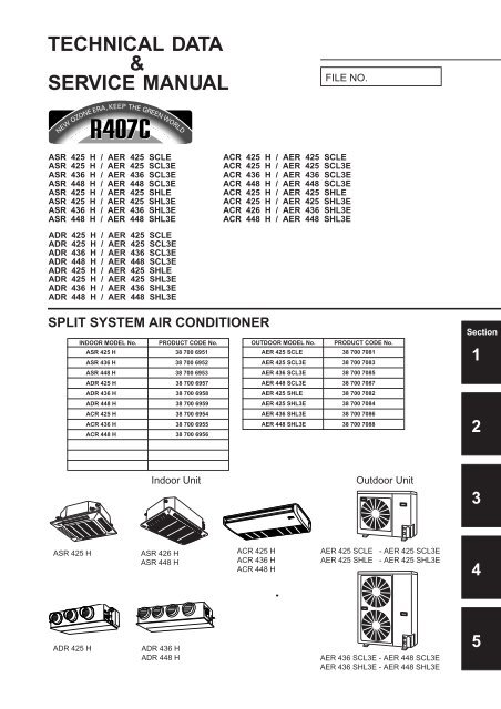
TECHNICAL DATA<br />
&<br />
SERVICE MANUAL<br />
ASR 425 H / AER 425 SCLE<br />
ASR 425 H / AER 425 SCL3E<br />
ASR 436 H / AER 436 SCL3E<br />
ASR 448 H / AER 448 SCL3E<br />
ASR 425 H / AER 425 SHLE<br />
ASR 425 H / AER 425 SHL3E<br />
ASR 436 H / AER 436 SHL3E<br />
ASR 448 H / AER 448 SHL3E<br />
ADR 425 H / AER 425 SCLE<br />
ADR 425 H / AER 425 SCL3E<br />
ADR 436 H / AER 436 SCL3E<br />
ADR 448 H / AER 448 SCL3E<br />
ADR 425 H / AER 425 SHLE<br />
ADR 425 H / AER 425 SHL3E<br />
ADR 436 H / AER 436 SHL3E<br />
ADR 448 H / AER 448 SHL3E<br />
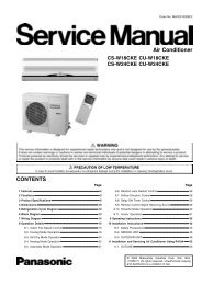
SPLIT SYSTEM AIR CONDITIONER<br />
ASR 425 H<br />
ADR 425 H<br />
INDOOR MODEL No. PRODUCT CODE No.<br />
ASR 425 H 38 700 6951<br />
ASR 436 H 38 700 6952<br />
ASR 448 H 38 700 6953<br />
ADR 425 H 38 700 6957<br />
ADR 436 H 38 700 6958<br />
ADR 448 H 38 700 6959<br />
ACR 425 H 38 700 6954<br />
ACR 436 H 38 700 6955<br />
ACR 448 H 38 700 6956<br />
FILE NO.<br />
ACR 425 H / AER 425 SCLE<br />
ACR 425 H / AER 425 SCL3E<br />
ACR 436 H / AER 436 SCL3E<br />
ACR 448 H / AER 448 SCL3E<br />
ACR 425 H / AER 425 SHLE<br />
ACR 425 H / AER 425 SHL3E<br />
ACR 426 H / AER 436 SHL3E<br />
ACR 448 H / AER 448 SHL3E<br />
OUTDOOR MODEL No. PRODUCT CODE No.<br />
AER 425 SCLE 38 700 7081<br />
AER 425 SCL3E 38 700 7083<br />
AER 436 SCL3E 38 700 7085<br />
AER 448 SCL3E 38 700 7087<br />
AER 425 SHLE 38 700 7082<br />
AER 425 SHL3E 38 700 7084<br />
AER 436 SHL3E 38 700 7086<br />
AER 448 SHL3E 38 700 7088<br />
Indoor Unit Outdoor Unit<br />
ASR 426 H<br />
ASR 448 H<br />
ADR 436 H<br />
ADR 448 H<br />
ACR 425 H<br />
ACR 436 H<br />
ACR 448 H<br />
AER 425 SCLE - AER 425 SCL3E<br />
AER 425 SHLE - AER 425 SHL3E<br />
AER 436 SCL3E - AER 448 SCL3E<br />
AER 436 SHL3E - AER 448 SHL3E<br />
Section<br />
1<br />
2<br />
3<br />
4<br />
5
Important<br />
Please Read Before Starting<br />
This air conditioning system meets strict safety and<br />
operating standards. As the installer or service person, it<br />
is an important part of your job to install or service the<br />
system so it operates safely and efficiently.<br />
For safe installation and trouble-free operation, you<br />
must :<br />
ⓦ Carefully read this instruction booklet before beginning.<br />
ⓦ Follow each installation or repair step exactly as shown.<br />
ⓦ Observe all local, state, and national electrical codes.<br />
ⓦ Pay close attention to all warning and caution notices<br />
given in this manual.<br />
CAUTION<br />
This symbol refers to a<br />
hazard or unsafe practice<br />
which can result in severe<br />
personal injury or death.<br />
This symbol refers to a<br />
hazard or unsafe practice<br />
which can result in personal<br />
injury or product or property<br />
damage.<br />
If Necessary, Get Help<br />
These instructions are all you need for most installation<br />
sites and maintenance conditions. If you require help for a<br />
special problem, contact our sales/service outlet or your<br />
certified dealer for additional instructions.<br />
In Case of Improper Installation<br />
The manufacturer shall in no way be responsible for<br />
improper installation or maintenance service, including<br />
failure to follow the instructions in this document.<br />
SPECIAL PRECAUTIONS<br />
When Wiring<br />
……………………………………………………………………<br />
ELECTRICAL SHOCK CAN CAUSE<br />
SEVERE PERSONAL INJURY OR DEATH.<br />
ONLY A QUALIFIED, EXPERIENCED<br />
ELECTRICIAN SHOULD ATTEMPT TO<br />
WIRE THIS SYSTEM.<br />
• Do not supply power to the unit until all wiring and<br />
tubing are completed or reconnected and checked.<br />
• Highly dangerous electrical voltages are used in this<br />
system. Carefully refer to the wiring diagram and these<br />
instructions when wiring. Improper connections and<br />
inadequate grounding can cause accidental injury or<br />
death.<br />
• Ground the unit following local electrical codes.<br />
• Connect all wiring tightly. Loose wiring may cause<br />
overheating at connection points and a possible fire<br />
hazard.<br />
When Transporting<br />
……………………………………………………………………<br />
Be careful when picking up and moving the indoor and<br />
outdoor units. Get a partner to help, and bend your knees<br />
when lifting to reduce strain on your back. Sharp edges or<br />
thin aluminum fins on the air conditioner can cut your<br />
fingers.<br />
When Installing<br />
……………………………………………………………………<br />
…In a Room<br />
Properly insulate any tubing run inside a room to prevent<br />
“sweating” that can cause dripping and water damage to<br />
walls and floors.<br />
…In Moist or Uneven Locations<br />
Use a raised concrete pad or concrete blocks to provide a<br />
solid, level foundation for the outdoor unit. This prevents<br />
water damage and abnormal vibration.<br />
…In an area with High Winds<br />
Securely anchor the outdoor unit down with bolts and a<br />
metal frame. Provide a suitable air baffle.<br />
…In a Snowy Area (for Heat Pump-type Systems)<br />
Install the outdoor unit on a raised platform that is higher<br />
than drifting snow. Provide snow vents.<br />
When Connecting Refrigerant Tubing<br />
……………………………………………………………………<br />
• Ventilate the room well, in the event that refrigerant gas<br />
leaks during the installation. Be careful not to allow<br />
contact of the refrigerant gas with a flame as this will<br />
cause the generation of poisonous gas.<br />
• Keep all tubing runs as short as possible.<br />
• Use the flare method for connecting tubing.<br />
• Apply refrigerant lubricant to the matching surfaces of<br />
the flare and union tubes before connecting them, then<br />
tighten the nut with a torque wrench for a leak-free<br />
connection.<br />
• Check carefully for leaks before starting the test run.<br />
NOTE<br />
Depending on the system type, liquid and gas lines may<br />
be either narrow or wide. Therefore, to avoid confusion the<br />
refrigerant tubing for your particular model is specified as<br />
either “narrow” or “wide” rather than as “liquid” or “gas”.<br />
When Servicing<br />
……………………………………………………………………<br />
• Turn the power OFF at the main power box (mains)<br />
before opening the unit to check or repair electrical<br />
parts and wiring.<br />
• Keep your fingers and clothing away from any moving<br />
parts.<br />
• Clean up the site when installation is finished. Check<br />
that no metal scraps or bits of wiring have been left<br />
inside the unit.<br />
CAUTION<br />
• Ventilate any enclosed areas when installing or testing<br />
the refrigeration system. Contact of refrigerant gas with<br />
fire or heat can produce poisonous gas.<br />
• Confirm after installation that no refrigerant gas is<br />
leaking. If the gas comes in contact with a burning<br />
stove, gas water heater, electric room heater or other<br />
heat source, it can cause the generation of poisonous<br />
gas.
WHO SHOULD USE THIS MANUAL<br />
This service manual is made to assist the service technician apply his knowledge and<br />
training to this model air conditioner. This manual is written both for experienced service<br />
persons and those who are new to air conditioning service. To help those with less<br />
experience or who are new to this kind of unit we have included more explanations of<br />
basic procedures in simple language than is usual in some service manuals. The experienced<br />
technician will of course find he knows many of these things already and can go<br />
directly to the procedures and information he needs; the less experienced technician will<br />
better understand what to do even before he arrives on the job, and therefore be better<br />
able to work by himself as well as assist the more experienced technician.<br />
TABLE OF CONTENTS<br />
1. SPECIFICATIONS............................................................................................ I - 1<br />
1-1 Unit Specifications .....................................................................................I - 2<br />
1-2 Major Component Specifications ...............................................................I - 34<br />
(A) Indoor Units..........................................................................................I - 34<br />
(B) Outdoor Units .......................................................................................I - 46<br />
1-3 Other Component Specifications ...............................................................I - 52<br />
1-4 Dimensional Data ......................................................................................I - 60<br />
(A) Indoor Units..........................................................................................I - 60<br />
(B) Outdoor Units .......................................................................................I - 67<br />
1-5 Refrigerant Flow Diagram ..........................................................................I - 69<br />
1-6 Operating Range .......................................................................................I - 72<br />
1-7 Cooling Capacity........................................................................................I - 73<br />
1-8 Noise Criterion Curves...............................................................................I - 90<br />
1-9 Indoor Fan Performance ............................................................................I - 95<br />
1-10 Air throw Distance Chart ............................................................................I - 97<br />
1-11 Installation Instructions ..............................................................................I - 99<br />
2. PROCESSES AND FUNCTIONS ......................................................................II - 1<br />
2-1 Room Temperature Control ......................................................................II - 2<br />
(A) Cooling ................................................................................................II - 2<br />
(B) Heating................................................................................................II - 3<br />
2-2 Cold Draft Prevention (Heating Cycle)......................................................II - 4<br />
2-3 Automatic Fan Speed (Indoor Unit) ..........................................................II - 5<br />
(A) Cooling ................................................................................................II - 5<br />
(B) Heating................................................................................................II - 5<br />
2-4 Outdoor Fan Speed Control......................................................................II - 6<br />
(A) Cooling ................................................................................................II - 6<br />
(B) Heating................................................................................................II - 6<br />
2-5 Freeze Prevention (Cooling) .....................................................................II - 7<br />
2-6 Condensing Temperature Control (Cooling) .............................................II - 8<br />
ii
2-7 Overload Protection (Heating) ..................................................................II - 9<br />
2-8 Discharge Temperature Control (Cooling and Heating) ...........................II - 10<br />
2-9 Auto. Mode for Automatic Heating/Cooling Switching ..............................II - 11<br />
2-10 Defrosting Control, Outdoor Heat Exchanger Coil (Heating) ....................II - 12<br />
2-11 4-Way Valve, Solenoid Control .................................................................II - 13<br />
(A) Normal Control Mode ..........................................................................II - 13<br />
(B) AUTO Control Mode ...........................................................................II - 14<br />
2-12 Automatic Restart after Power Interruption...............................................II - 14<br />
2-13 Electronic Expansion Control Valve..........................................................II - 15<br />
2-14 Compressor Discharge Gas Temperature ................................................II - 15<br />
(A) Cooling ................................................................................................II - 15<br />
(B) Heating (Except During Defrosting) ....................................................II - 15<br />
2-15 Compressor Current Detection Circuit ......................................................II - 16<br />
2-16 Dehumidifying Operation ..........................................................................II - 17<br />
2-17 Auto-flap Control .......................................................................................II - 18<br />
2-18 Controlled by Electronic Expansion Valve ................................................II - 19<br />
2-19 Voltage Detection Control .........................................................................II - 20<br />
3. ELECTRICAL DATA ........................................................................................III - 1<br />
3-1 Indoor Unit (Electric Wiring Diagram, Schematic Diagram) .....................III - 2<br />
3-2 Outdoor Unit (Electric Wiring Diagram, Schematic Diagram) ..................III - 14<br />
4. SERVICE PROCEDURES............................................................................... IV - 1<br />
4-1 Troubleshooting ...................................................................................... IV - 2<br />
4-2 Checking the Electrical Components ...................................................... IV - 36<br />
5. APPENDIX ....................................................................................................... V - 1<br />
5-1 P.C.B. ...................................................................................................... V - 2<br />
iii
Introduction: Read Me First!<br />
This manual will help you understand WHAT and service IS the IN air THIS conditioner. MANUAL<br />
To help you find the information you<br />
need, we have divided it into 5 main sections. Each section is divided into chapters with charts, tables and<br />
explanations to help you find and repair problems.<br />
❑ Section 1: Specifications, tells you about the physical and electrical make up of the unit, as<br />
well as its heating and cooling capacities. Look in this section to find the correct values for<br />
components and functions.<br />
❑ Section 2: Processes and Functions, explains each different part of the cooling and<br />
heating cycle, and how each control function reacts to changing conditions to keep the room<br />
at the set temperature range.<br />
❑ Section 3: Electrical Data, which has fold-out schematic and wiring diagrams so you can<br />
find the parts you need to check when something is wrong, and see how they should be<br />
connected.<br />
❑ Section 4: Service Procedures, has two main parts, a diagnostic chapter to help you find<br />
the specific component to replace or adjust, and a chapter with specific procedures and<br />
values to guide you in checking the electrical components in the unit.<br />
HOW TO USE THIS MANUAL<br />
You can use this manual both as a reference to find specific information about the capacity, functions and<br />
construction of this unit, and as a source of information to help you set up and maintain the unit.<br />
When this unit is not working properly, and the cause is not known, you can use the procedures in<br />
Section 3: Servicing Procedures to find the problem, fix it, and restore the unit to its proper functioning.<br />
This air conditioner has many helpful self diagnostic features to help you identify problem areas quickly.<br />
So you will be ready when a problem happens, we suggest you look this manual over and become familiar<br />
with it by following these steps:<br />
1. Look at the TABLE OF CONTENTS to get an idea of what is in this manual and where to<br />
find it.<br />
2. Look at the chapter about TROUBLE SHOOTING, so you are familiar with the way the flow<br />
charts work. They are designed to guide you quickly through the possible causes for each<br />
kind of problem that is likely to happen to the Unit. Particularly read the introduction to this<br />
section, and the parts about the self-diagnosis and error codes which show on the display.<br />
3. Look at the chapter about CHECKING ELECTRICAL COMPONENTS. You already know<br />
about most of these procedures. This chapter gives you the specific values and methods for<br />
these components. If you don’t know some of these procedures, you can easily learn them<br />
here.<br />
4. Read the Instruction Manual! The Instruction Manual is included here because it helps you<br />
help the user to set the temperature controls properly and know how to take care of any<br />
simple problems that may happen, as well as know when to call for service. The Instruction<br />
Manual also has illustrations, care, and installation information not found in the rest of the<br />
service manual. It is short, and if you read it carefully, you will be able to answer the<br />
customers questions easily, and also know the most efficient ways for setting times and<br />
temperatures.<br />
Please use this manual to make your work easier, keep the air conditioner functioning well, and keep your<br />
customers satisfied.<br />
iv
1. SPECIFICATIONS<br />
1. Specifications<br />
1-1 Unit Specifications ................................................................................. I - 2<br />
4-Way Air Discharge Semi-concealed Type ........................................... I - 2<br />
Ceiling Mounted Type .............................................................................. I - 10<br />
Concealed Duct Type .............................................................................. I - 18<br />
Concealed Duct High Static Pressure Type ............................................ I - 26<br />
1-2 Major Component Specifications ............................................................. I - 34<br />
(A) Indoor Units ........................................................................................ I - 34<br />
(B) Outdoor Units ..................................................................................... I - 46<br />
1-3 Other Component Specifications ............................................................. I - 52<br />
4-Way Air Discharge Semi-concealed Type ........................................... I - 52<br />
Ceiling Mounted Type .............................................................................. I - 53<br />
Concealed Duct High Static Pressure Type ............................................ I - 54<br />
Concealed Duct Type .............................................................................. I - 55<br />
Outdoor Units........................................................................................... I - 56<br />
1-4 Dimensional Data .................................................................................... I - 60<br />
(A) Indoor Units ........................................................................................ I - 60<br />
4-Way Air Discharge Semi-concealed Type....................................... I - 60<br />
Ceiling Mounted Type ........................................................................ I - 62<br />
Concealed Duct Type ......................................................................... I - 63<br />
Concealed Duct High Static Pressure Type ....................................... I - 66<br />
(B) Outdoor Units ..................................................................................... I - 67<br />
1-5 Refrigerant Flow Operating Range .......................................................... I - 69<br />
1-6 Operating Range ..................................................................................... I - 72<br />
1-7 Cooling Capacity...................................................................................... I - 73<br />
1-8 Noise Criterion Curves............................................................................. I - 90<br />
1-9 Indoor Fan Performance .......................................................................... I - 95<br />
1-10 Air throw Distance Chart .......................................................................... I - 97<br />
1-11 Installation Instructions ............................................................................ I - 99<br />
Tubing Length .......................................................................................... I - 99<br />
Selecting the Installation Site................................................................... I -100<br />
Electrical Wiring ....................................................................................... I -104<br />
Electrical Characteristics ......................................................................... I -107<br />
I - 1<br />
1<br />
2<br />
3<br />
4<br />
5
1<br />
12<br />
3<br />
4<br />
5<br />
1-1 Unit Specifications<br />
4-Way Air Discharge Semi-concealed Type<br />
I - 2<br />
1. Specifications<br />
MODEL No. Indoor Unit ASR 425 H<br />
Outdoor Unit AER 425 SCLE<br />
POWER SOURCE 220 - 230 - 240 V / 1 phase / 50 Hz<br />
PERFORMANCE Cooling<br />
Capacity kW 7.3<br />
BTU / h 25,000<br />
Air circulation (Hi / Me / Lo) m3 /h 1,140 / 1,020 / 840<br />
Moisture removal (High)<br />
ELECTRICAL RATINGS<br />
Liters/h 3.6<br />
Voltage rating V 220 230 240<br />
Available voltage range V 198 – 264<br />
Running amperes* A 13.32 13.46 13.58<br />
Max. running amperes** A 14.66 14.72 14.76<br />
Power input kW 2.81 2.93 3<br />
C.O.P W / W 2.6 2.49 2.43<br />
Max. starting amperes<br />
FEATURES<br />
A 69 72 75<br />
Controls / Thermostat control Microprocessor / I.C. thermostat<br />
Timer ON / OFF 72-hours ON/OFF 24-hours & Program<br />
Fan speeds Indoor / Outdoor 3 and Automatic control / 3 (Auto)<br />
Airflow direction (Indoor) Automatic (Remote control)<br />
Air filter Washable, easy access, long life (2,500 hr)<br />
Remote controller (Option) Wired : REM HW A Wireless : REM CLR A<br />
Refrigerant control Electronic expansion valve<br />
Drain pump (Drain connection) Max. head 25 cm above drain connection (25A, OD32 mm)<br />
Compressor Rotary (Sanyo)<br />
Operation sound Indoor - Hi/Me/Lo dB - A 37 / 35 / 31<br />
Outdoor - Hi dB - A 52<br />
Color (Approximate value) Indoor Munsell 10Y9.3 / 0.4, RAL 9010-GL<br />
REFRIGERANT TUBING<br />
Outdoor Munsell 5Y8.4 / 0.5, RAL 9002-GL<br />
Limit of tubing length m (ft.) 50 (164 )<br />
Limit of tubing length at shipment m (ft.) 30 ( 98 )<br />
Limit of elevation difference m (ft.) Outdoor unit is higher than indoor unit : 50 (164)<br />
between the two units Outdoor unit is lower than indoor unit : 30 (98)<br />
Refrigerant tube Narrow tube mm (in.) 6.35 (1 / 4)<br />
outer diameter Wide tube mm (in.) 15.88 (5 / 8)<br />
Refrigerant amount at shipment kg R407C - 3.2<br />
DIMENSIONS & WEIGHT Indoor unit (Include panel) Outdoor unit<br />
Unit dimensions Height mm (in.) 328 ( 12 - 29 / 32) 735 (28 - 30 / 32)<br />
Width mm (in.) 860 ( 33 - 27 / 32) 940 (37 )<br />
Depth mm (in.) 860 ( 33 - 27 / 32) 340 (13 - 12 / 32)<br />
Package dimensions Body : ASR 425 H Panel : ASG 0025 Outdoor unit<br />
Height mm (in.) 284 (11 - 6 / 32) 104 ( 4 - 3 / 32) 826 (32 - 17 / 32)<br />
Width mm (in.) 824 (32 - 14 / 32) 967 (38 - 2 / 32) 1,016 (40 )<br />
Depth mm (in.) 833 (32 - 25 / 32) 999 (39 - 11 / 32) 416 (16 - 12 / 32)<br />
Net weight kg (lb.) 30 (66) 69 ( 152)<br />
Shipping weight kg (lb.) 27 ( 60 ) 8 ( 18) 75 ( 165 )<br />
Shipping volume m3 (cu. ft) 0.195 ( 6.9 ) 0.1 ( 3.5) 0.349 (12.3)<br />
DATA SUBJECT TO CHANGE WITHOUT NOTICE.<br />
Cooling:<br />
Rating conditions (*): Indoor air temperature 27 °C DB/19 °C WB, Outdoor air temperature 35 °C DB<br />
Full load conditions (**): Indoor air temperature 32 °C DB/23 °C WB, Outdoor air temperature 43 °C DB
1-1 Unit Specifications<br />
4-Way Air Discharge Semi-concealed Type<br />
1. Specifications<br />
MODEL No. Indoor Unit ASR 425 H<br />
Outdoor Unit AER 425 SCL3E<br />
POWER SOURCE 380 - 400 - 415 V / 3N / 50 Hz<br />
PERFORMANCE Cooling<br />
Capacity kW 7.3<br />
BTU / h 25,000<br />
Air circulation (Hi / Me / Lo) m3 /h 1,140 / 1,020 / 840<br />
Moisture removal (High)<br />
ELECTRICAL RATINGS<br />
Liters/h 3.6<br />
Voltage rating V 380 400 415<br />
Available voltage range V 342 – 456<br />
Running amperes* A 4.82 4.78 4.73<br />
Max. running amperes** A 5.67 5.68 5.69<br />
Power input kW 2.76 2.79 2.82<br />
C.O.P W / W 2.64 2.62 2.59<br />
Max. starting amperes<br />
FEATURES<br />
A 27 29 30<br />
Controls / Thermostat control Microprocessor / I.C. thermostat<br />
Timer ON / OFF 72-hours ON/OFF 24-hours & Program<br />
Fan speeds Indoor / Outdoor 3 and Automatic control / 3 (Auto)<br />
Airflow direction (Indoor) Automatic (Remote control)<br />
Air filter Washable, easy access, long life (2,500 hr)<br />
Remote controller (Option) Wired : REM HW A Wireless : REM CLR A<br />
Refrigerant control Electronic expansion valve<br />
Drain pump (Drain connection) Max. head 25 cm above drain connection (25A, OD32 mm)<br />
Compressor Rotary (Sanyo)<br />
Operation sound Indoor - Hi/Me/Lo dB - A 37 / 35 / 31<br />
Outdoor - Hi dB - A 52<br />
Color (Approximate value) Indoor Munsell 10Y9.3 / 0.4, RAL 9010-GL<br />
REFRIGERANT TUBING<br />
Outdoor Munsell 5Y8.4 / 0.5, RAL 9002-GL<br />
Limit of tubing length m (ft.) 50 (164 )<br />
Limit of tubing length at shipment m (ft.) 30 ( 98 )<br />
Limit of elevation difference m (ft.) Outdoor unit is higher than indoor unit : 50 (164)<br />
between the two units Outdoor unit is lower than indoor unit : 30 (98)<br />
Refrigerant tube Narrow tube mm (in.) 6.35 (1 / 4)<br />
outer diameter Wide tube mm (in.) 15.88 (5 / 8)<br />
Refrigerant amount at shipment kg R407C - 3.2<br />
DIMENSIONS & WEIGHT Indoor unit (Include panel) Outdoor unit<br />
Unit dimensions Height mm (in.) 328 ( 12 - 29 / 32) 735 (28 - 30 / 32)<br />
Width mm (in.) 860 ( 33 - 27 / 32) 940 (37 )<br />
Depth mm (in.) 860 ( 33 - 27 / 32) 340 (13 - 12 / 32)<br />
Package dimensions Body : ASR 425 H Panel : ASG 0025 Outdoor unit<br />
Height mm (in.) 284 (11 - 6 / 32) 104 ( 4 - 3 / 32) 826 (32 - 17 / 32)<br />
Width mm (in.) 824 (32 - 14 / 32) 967 (38 - 2 / 32) 1,016 (40 )<br />
Depth mm (in.) 833 (32 - 25 / 32) 999 (39 - 11 / 32) 416 (16 - 12 / 32)<br />
Net weight kg (lb.) 30 (66) 69 ( 152)<br />
Shipping weight kg (lb.) 27 ( 60) 8 ( 18) 75 ( 165)<br />
Shipping volume m3 (cu. ft) 0.195 ( 6.9) 0.1 ( 3.5) 0.349 (12.3)<br />
DATA SUBJECT TO CHANGE WITHOUT NOTICE.<br />
Cooling:<br />
Rating conditions (*): Indoor air temperature 27 °C DB/19 °C WB, Outdoor air temperature 35 °C DB<br />
Full load conditions (**): Indoor air temperature 32 °C DB/23 °C WB, Outdoor air temperature 43 °C DB<br />
I - 3<br />
1<br />
2<br />
3<br />
4<br />
5
1<br />
12<br />
3<br />
4<br />
5<br />
1-1 Unit Specifications<br />
4-Way Air Discharge Semi-concealed Type<br />
I - 4<br />
1. Specifications<br />
MODEL No. Indoor Unit ASR 436 H<br />
Outdoor Unit AER 436 SCL3E<br />
POWER SOURCE 380 - 400 - 415 V / 3N / 50 Hz<br />
PERFORMANCE Cooling<br />
Capacity kW 10.6<br />
BTU / h 36,000<br />
Air circulation (Hi / Me / Lo) m3 /h 1,920 / 1,680 / 1,320<br />
Moisture removal (High)<br />
ELECTRICAL RATINGS<br />
Liters/h 4.6<br />
Voltage rating V 380 400 415<br />
Available voltage range V 342 – 456<br />
Running amperes* A 7.01 7.02 7.05<br />
Max. running amperes** A 7.86 7.87 7.9<br />
Power input kW 3.92 3.97 4.02<br />
C.O.P W / W 2.7 2.67 2.64<br />
Max. starting amperes<br />
FEATURES<br />
A 47 49 50<br />
Controls / Thermostat control Microprocessor / I.C. thermostat<br />
Timer ON / OFF 72-hours ON/OFF 24-hours & Program<br />
Fan speeds Indoor / Outdoor 3 and Automatic control / 3 (Auto)<br />
Airflow direction (Indoor) Automatic (Remote control)<br />
Air filter Washable, easy access, long life (2,500 hr)<br />
Remote controller (Option) Wired : REM HW A Wireless : REM CLR A<br />
Refrigerant control Electronic expansion valve<br />
Drain pump (Drain connection) Max. head 25 cm above drain connection (25A, OD32 mm)<br />
Compressor Scroll (Sanyo)<br />
Operation sound Indoor - Hi/Me/Lo dB - A 43 / 40 / 36<br />
Outdoor - Hi dB - A 53<br />
Color (Approximate value) Indoor Munsell 10Y9.3 / 0.4, RAL 9010-GL<br />
REFRIGERANT TUBING<br />
Outdoor Munsell 5Y8.4 / 0.5, RAL 9002-GL<br />
Limit of tubing length m (ft.) 50 (164 )<br />
Limit of tubing length at shipment m (ft.) 30 ( 98 )<br />
Limit of elevation difference m (ft.) Outdoor unit is higher than indoor unit : 50 (164)<br />
between the two units Outdoor unit is lower than indoor unit : 30 (98)<br />
Refrigerant tube Narrow tube mm (in.) 9.52 (3 / 8)<br />
outer diameter Wide tube mm (in.) 19.05 (3 / 4)<br />
Refrigerant amount at shipment kg R407C - 4.0<br />
DIMENSIONS & WEIGHT Indoor unit (Include panel) Outdoor unit<br />
Unit dimensions Height mm (in.) 358 ( 14 - 3 / 32) 1,235 (48 - 20 / 32)<br />
Width mm (in.) 1,150 ( 45 - 9 / 32) 940 (37 )<br />
Depth mm (in.) 860 ( 33 - 27 / 32) 340 (13 - 12 / 32)<br />
Package dimensions Body : ASR 436 H Panel : ASG 3648 Outdoor unit<br />
Height mm (in.) 316 (12 - 14 / 32) 104 ( 4 - 3 / 32) 1,326 (52 - 7 / 32)<br />
Width mm (in.) 1,114 (43 - 27 / 32) 1,257 (49 - 16 / 32) 1,016 (40 )<br />
Depth mm (in.) 860 (33 - 27 / 32) 999 (39 - 11 / 32) 416 (16 - 12 / 32)<br />
Net weight kg (lb.) 38 (84) 104 ( 229)<br />
Shipping weight kg (lb.) 32 ( 71 ) 10 ( 22) 111 ( 245 )<br />
Shipping volume m3 (cu. ft) 0.303 (10.7) 0.131 ( 4.6) 0.56 (19.8)<br />
DATA SUBJECT TO CHANGE WITHOUT NOTICE.<br />
Cooling:<br />
Rating conditions (*): Indoor air temperature 27 °C DB/19 °C WB, Outdoor air temperature 35 °C DB<br />
Full load conditions (**): Indoor air temperature 32 °C DB/23 °C WB, Outdoor air temperature 43 °C DB
1-1 Unit Specifications<br />
4-Way Air Discharge Semi-concealed Type<br />
1. Specifications<br />
MODEL No. Indoor Unit ASR 448 H<br />
Outdoor Unit AER 448 SCL3E<br />
POWER SOURCE 380 - 400 - 415 V / 3N / 50 Hz<br />
PERFORMANCE Cooling<br />
Capacity kW 12.6<br />
BTU / h 43,000<br />
Air circulation (Hi / Me / Lo) m3 /h 1,920 / 1,680 / 1,320<br />
Moisture removal (High)<br />
ELECTRICAL RATINGS<br />
Liters/h 6.3<br />
Voltage rating V 380 400 415<br />
Available voltage range V 342 – 456<br />
Running amperes* A 8.35 8.35 8.37<br />
Max. running amperes** A 9.47 9.47 9.49<br />
Power input kW 4.6 4.64 4.67<br />
C.O.P W / W 2.74 2.72 2.70<br />
Max. starting amperes<br />
FEATURES<br />
A 53 56 58<br />
Controls / Thermostat control Microprocessor / I.C. thermostat<br />
Timer ON / OFF 72-hours ON/OFF 24-hours & Program<br />
Fan speeds Indoor / Outdoor 3 and Automatic control / 3 (Auto)<br />
Airflow direction (Indoor) Automatic (Remote control)<br />
Air filter Washable, easy access, long life (2,500 hr)<br />
Remote controller (Option) Wired : REM HW A Wireless : REM CLR A<br />
Refrigerant control Electronic expansion valve<br />
Drain pump (Drain connection) Max. head 25 cm above drain connection (25A, OD32 mm)<br />
Compressor Scroll (Sanyo)<br />
Operation sound Indoor - Hi/Me/Lo dB - A 43 / 40 / 36<br />
Outdoor - Hi dB - A 55<br />
Color (Approximate value) Indoor Munsell 10Y9.3 / 0.4, RAL 9010-GL<br />
REFRIGERANT TUBING<br />
Outdoor Munsell 5Y8.4 / 0.5, RAL 9002-GL<br />
Limit of tubing length m (ft.) 50 (164 )<br />
Limit of tubing length at shipment m (ft.) 30 ( 98 )<br />
Limit of elevation difference m (ft.) Outdoor unit is higher than indoor unit : 50 (164)<br />
between the two units Outdoor unit is lower than indoor unit : 30 (98)<br />
Refrigerant tube Narrow tube mm (in.) 9.52 (3 / 8)<br />
outer diameter Wide tube mm (in.) 19.05 (3 / 4)<br />
Refrigerant amount at shipment kg R407C - 4.5<br />
DIMENSIONS & WEIGHT Indoor unit (Include panel) Outdoor unit<br />
Unit dimensions Height mm (in.) 358 ( 14 - 3 / 32) 1,235 (48 - 20 / 32)<br />
Width mm (in.) 1,150 ( 45 - 9 / 32) 940 (37 )<br />
Depth mm (in.) 860 ( 33 - 27 / 32) 340 (13 - 12 / 32)<br />
Package dimensions Body : SASR 448 H Panel : ASG 3648 Outdoor unit<br />
Height mm (in.) 316 (12 - 14 / 32) 104 ( 4 - 3 / 32) 1,326 (52 - 7 / 32)<br />
Width mm (in.) 1,114 (43 - 27 / 32) 1,257 (49 - 16 / 32) 1,016 (40 )<br />
Depth mm (in.) 860 (33 - 27 / 32) 999 (39 - 11 / 32) 416 (16 - 12 / 32)<br />
Net weight kg (lb.) 38 (84) 106 ( 234)<br />
Shipping weight kg (lb.) 32 ( 71 ) 10 ( 22) 113 ( 249 )<br />
Shipping volume m3 (cu. ft) 0.303 (10.7) 0.131 ( 4.6) 0.56 (19.8)<br />
DATA SUBJECT TO CHANGE WITHOUT NOTICE.<br />
Cooling:<br />
Rating conditions (*): Indoor air temperature 27 °C DB/19 °C WB, Outdoor air temperature 35 °C DB<br />
Full load conditions (**): Indoor air temperature 32 °C DB/23 °C WB, Outdoor air temperature 43 °C DB<br />
I - 5<br />
1<br />
2<br />
3<br />
4<br />
5
1<br />
12<br />
3<br />
4<br />
5<br />
1-1 Unit Specifications<br />
4-Way Air Discharge Semi-concealed Type<br />
I - 6<br />
1. Specifications<br />
MODEL No. Indoor Unit ASR 425 H<br />
Outdoor Unit AER 425 SHLE<br />
POWER SOURCE 220 - 230 - 240 V / 1 phase / 50 Hz<br />
PERFORMANCE Cooling Heating<br />
Capacity kW 7.3 8.6<br />
BTU / h 25,000 29,300<br />
Air circulation (Hi / Me / Lo) m 3 /h 1,140 / 1,020 / 840<br />
Moisture removal (High) Liters/h 3.6 —<br />
ELECTRICAL RATINGS<br />
Voltage rating V 220 230 240 220 230 240<br />
Available voltage range V 198 – 264 198 – 264<br />
Running amperes* A 13.32 13.46 13.58 14.69 14.64 14.57<br />
Max. running amperes** A 14.66 14.72 14.76 16.59 16.94 16.27<br />
Power input kW 2.81 2.93 3 3.07 3.14 3.21<br />
C.O.P W / W 2.6 2.49 2.43 2.8 2.74 2.68<br />
Max. starting amperes A 69 72 75 69 72 75<br />
FEATURES<br />
Controls / Thermostat control Microprocessor / I.C. thermostat<br />
Timer ON / OFF 72-hours ON/OFF 24-hours & Program<br />
Fan speeds Indoor / Outdoor 3 and Automatic control / 3 (Auto)<br />
Airflow direction (Indoor) Automatic (Remote control)<br />
Air filter Washable, easy access, long life (2,500 hr)<br />
Remote controller (Option) Wired : REM HW A Wireless : REM HL A<br />
Refrigerant control Electronic expansion valve<br />
Drain pump (Drain connection) Max. head 25 cm above drain connection (25A, OD32 mm)<br />
Compressor Rotary (Sanyo)<br />
Operation sound Indoor - Hi/Me/Lo dB - A 37 / 35 / 31<br />
Outdoor - Hi dB - A 52<br />
Color (Approximate value) Indoor Munsell 10Y9.3 / 0.4, RAL 9010-GL<br />
Outdoor Munsell 5Y8.4 / 0.5, RAL 9002-GL<br />
REFRIGERANT TUBING<br />
Limit of tubing length m (ft.) 50 (164 )<br />
Limit of tubing length at shipment m (ft.) 30 ( 98 )<br />
Limit of elevation difference m (ft.) Outdoor unit is higher than indoor unit : 50 (164)<br />
between the two units Outdoor unit is lower than indoor unit : 30 (98)<br />
Refrigerant tube Narrow tube mm (in.) 6.35 (1 / 4)<br />
outer diameter Wide tube mm (in.) 15.88 (5 / 8)<br />
Refrigerant amount at shipment kg R407C - 3.2<br />
DIMENSIONS & WEIGHT Indoor unit (Include panel) Outdoor unit<br />
Unit dimensions Height mm (in.) 328 ( 12 - 29 / 32) 735 (28 - 30 / 32)<br />
Width mm (in.) 860 ( 33 - 27 / 32) 940 (37 )<br />
Depth mm (in.) 860 ( 33 - 27 / 32) 340 (13 - 12 / 32)<br />
Package dimensions Body : ASR 425 H Panel : ASG 0025 Outdoor unit<br />
Height mm (in.) 284 (11 - 6 / 32) 104 ( 4 - 3 / 32) 826 (32 - 17 / 32)<br />
Width mm (in.) 824 (32 - 14 / 32) 967 (38 - 2 / 32) 1,016 (40 )<br />
Depth mm (in.) 833 (32 - 25 / 32) 999 (39 - 11 / 32) 416 (16 - 12 / 32)<br />
Net weight kg (lb.) 30 (66) 71 ( 157)<br />
Shipping weight kg (lb.) 27 ( 60 ) 8 ( 18) 77 ( 170 )<br />
Shipping volume m 3 (cu. ft) 0.195 ( 6.9 ) 0.1 ( 3.5) 0.349 (12.3)<br />
DATA SUBJECT TO CHANGE WITHOUT NOTICE.<br />
Cooling:<br />
Rating conditions (*): Indoor air temperature 27 °C DB/19 °C WB, Outdoor air temperature 35 °C DB<br />
Full load conditions (**): Indoor air temperature 32 °C DB/23 °C WB, Outdoor air temperature 43 °C DB<br />
Heating:<br />
Rating conditions (*): Indoor air temperature 20 °C DB, Outdoor air temperature 7 °C DB / 6 °C WB<br />
Full load conditions (**): Indoor air temperature 24 °C DB, Outdoor air temperature 24 °C DB / 15.5 °C WB
1-1 Unit Specifications<br />
4-Way Air Discharge Semi-concealed Type<br />
1. Specifications<br />
MODEL No. Indoor Unit ASR 425 H<br />
Outdoor Unit AER 425 SHL3E<br />
POWER SOURCE 380 - 400 - 415 V / 3N / 50 Hz<br />
PERFORMANCE Cooling Heating<br />
Capacity kW 7.3 8.6<br />
BTU / h 25,000 29,300<br />
Air circulation (Hi / Me / Lo) m 3 /h 1,140 / 1,020 / 840<br />
Moisture removal (High) Liters/h 3.6 —<br />
ELECTRICAL RATINGS<br />
Voltage rating V 380 400 415 380 400 415<br />
Available voltage range V 342 – 456 342 – 456<br />
Running amperes* A 4.82 4.78 4.73 5.31 5.21 5.12<br />
Max. running amperes** A 5.67 5.68 5.69 5.41 5.32 5.22<br />
Power input kW 2.76 2.79 2.82 3 3.03 3.06<br />
C.O.P W / W 2.64 2.62 2.59 2.87 2.84 2.81<br />
Max. starting amperes A 27 29 30 27 29 30<br />
FEATURES<br />
Controls / Thermostat control Microprocessor / I.C. thermostat<br />
Timer ON / OFF 72-hours ON/OFF 24-hours & Program<br />
Fan speeds Indoor / Outdoor 3 and Automatic control / 3 (Auto)<br />
Airflow direction (Indoor) Automatic (Remote control)<br />
Air filter Washable, easy access, long life (2,500 hr)<br />
Remote controller (Option) Wired : REM HW A Wireless : REM HL A<br />
Refrigerant control Electronic expansion valve<br />
Drain pump (Drain connection) Max. head 25 cm above drain connection (25A, OD32 mm)<br />
Compressor Rotary (Sanyo)<br />
Operation sound Indoor - Hi/Me/Lo dB - A 37 / 35 / 31<br />
Outdoor - Hi dB - A 52<br />
Color (Approximate value) Indoor Munsell 10Y9.3 / 0.4, RAL 9010-GL<br />
Outdoor Munsell 5Y8.4 / 0.5, RAL 9002-GL<br />
REFRIGERANT TUBING<br />
Limit of tubing length m (ft.) 50 (164 )<br />
Limit of tubing length at shipment m (ft.) 30 ( 98 )<br />
Limit of elevation difference m (ft.) Outdoor unit is higher than indoor unit : 50 (164)<br />
between the two units Outdoor unit is lower than indoor unit : 30 (98)<br />
Refrigerant tube Narrow tube mm (in.) 6.35 (1 / 4)<br />
outer diameter Wide tube mm (in.) 15.88 (5 / 8)<br />
Refrigerant amount at shipment kg R407C - 3.2<br />
DIMENSIONS & WEIGHT Indoor unit (Include panel) Outdoor unit<br />
Unit dimensions Height mm (in.) 328 ( 12 - 29 / 32) 735 (28 - 30 / 32)<br />
Width mm (in.) 860 ( 33 - 27 / 32) 940 (37 )<br />
Depth mm (in.) 860 ( 33 - 27 / 32) 340 (13 - 12 / 32)<br />
Package dimensions Body : ASR 425 H Panel : ASG 0025 Outdoor unit<br />
Height mm (in.) 284 (11 - 6 / 32) 104 ( 4 - 3 / 32) 826 (32 - 17 / 32)<br />
Width mm (in.) 824 (32 - 14 / 32) 967 (38 - 2 / 32) 1,016 (40 )<br />
Depth mm (in.) 833 (32 - 25 / 32) 999 (39 - 11 / 32) 416 (16 - 12 / 32)<br />
Net weight kg (lb.) 30 (66) 71 ( 157)<br />
Shipping weight kg (lb.) 27 ( 60 ) 8 ( 18) 77 ( 170 )<br />
Shipping volume m 3 (cu. ft) 0.195 ( 6.9 ) 0.1 ( 3.5) 0.349 (12.3)<br />
DATA SUBJECT TO CHANGE WITHOUT NOTICE.<br />
Cooling:<br />
Rating conditions (*): Indoor air temperature 27 °C DB/19 °C WB, Outdoor air temperature 35 °C DB<br />
Full load conditions (**): Indoor air temperature 32 °C DB/23 °C WB, Outdoor air temperature 43 °C DB<br />
Heating:<br />
Rating conditions (*): Indoor air temperature 20 °C DB, Outdoor air temperature 7 °C DB / 6 °C WB<br />
Full load conditions (**): Indoor air temperature 24 °C DB, Outdoor air temperature 24 °C DB / 15.5 °C WB<br />
I - 7<br />
1<br />
2<br />
3<br />
4<br />
5
1<br />
12<br />
3<br />
4<br />
5<br />
1-1 Unit Specifications<br />
4-Way Air Discharge Semi-concealed Type<br />
I - 8<br />
1. Specifications<br />
MODEL No. Indoor Unit ASR 436 H<br />
Outdoor Unit AER 436 SHL3E<br />
POWER SOURCE 380 - 400 - 415 V / 3N / 50 Hz<br />
PERFORMANCE Cooling Heating<br />
Capacity kW 10.6 12.5<br />
BTU / h 36,000 42,700<br />
Air circulation (Hi / Me / Lo) m 3 /h 1,920 / 1,680 / 1,320<br />
Moisture removal (High) Liters/h 4.6 —<br />
ELECTRICAL RATINGS<br />
Voltage rating V 380 400 415 380 400 415<br />
Available voltage range V 342 – 456 342 – 456<br />
Running amperes* A 7.01 7.02 7.05 7.58 7.6 7.64<br />
Max. running amperes** A 7.86 7.87 7.9 7.98 8 8.04<br />
Power input kW 3.92 3.97 4.02 4.26 4.3 4.33<br />
C.O.P W / W 2.7 2.67 2.64 2.93 2.91 2.89<br />
Max. starting amperes A 47 49 50 47 49 50<br />
FEATURES<br />
Controls / Thermostat control Microprocessor / I.C. thermostat<br />
Timer ON / OFF 72-hours ON/OFF 24-hours & Program<br />
Fan speeds Indoor / Outdoor 3 and Automatic control / 3 (Auto)<br />
Airflow direction (Indoor) Automatic (Remote control)<br />
Air filter Washable, easy access, long life (2,500 hr)<br />
Remote controller (Option) Wired : REM HW A Wireless : REM HL A<br />
Refrigerant control Electronic expansion valve<br />
Drain pump (Drain connection) Max. head 25 cm above drain connection (25A, OD32 mm)<br />
Compressor Scroll (Sanyo)<br />
Operation sound Indoor - Hi/Me/Lo dB - A 43 / 40 / 36<br />
Outdoor - Hi dB - A 53<br />
Color (Approximate value) Indoor Munsell 10Y9.3 / 0.4, RAL 9010-GL<br />
Outdoor Munsell 5Y8.4 / 0.5, RAL 9002-GL<br />
REFRIGERANT TUBING<br />
Limit of tubing length m (ft.) 50 (164 )<br />
Limit of tubing length at shipment m (ft.) 30 ( 98 )<br />
Limit of elevation difference m (ft.) Outdoor unit is higher than indoor unit : 50 (164)<br />
between the two units Outdoor unit is lower than indoor unit : 30 (98)<br />
Refrigerant tube Narrow tube mm (in.) 9.52 (3 / 8)<br />
outer diameter Wide tube mm (in.) 19.05 (3 / 4)<br />
Refrigerant amount at shipment kg R407C - 4.0<br />
DIMENSIONS & WEIGHT Indoor unit (Include panel) Outdoor unit<br />
Unit dimensions Height mm (in.) 358 ( 14 - 3 / 32) 1,235 (48 - 20 / 32)<br />
Width mm (in.) 1,150 ( 45 - 9 / 32) 940 (37 )<br />
Depth mm (in.) 860 ( 33 - 27 / 32) 340 (13 - 12 / 32)<br />
Package dimensions Body : ASR 436 H Panel : ASG 3648 Outdoor unit<br />
Height mm (in.) 316 (12 - 14 / 32) 104 ( 4 - 3 / 32) 1,326 (52 - 7 / 32)<br />
Width mm (in.) 1,114 (43 - 27 / 32) 1,257 (49 - 16 / 32) 1,016 (40 )<br />
Depth mm (in.) 860 (33 - 27 / 32) 999 (39 - 11 / 32) 416 (16 - 12 / 32)<br />
Net weight kg (lb.) 38 (84) 106 ( 234)<br />
Shipping weight kg (lb.) 32 ( 71 ) 10 ( 22) 113 ( 249 )<br />
Shipping volume m 3 (cu. ft) 0.303 (10.7) 0.131 ( 4.6) 0.56 (19.8)<br />
DATA SUBJECT TO CHANGE WITHOUT NOTICE.<br />
Cooling:<br />
Rating conditions (*): Indoor air temperature 27 °C DB/19 °C WB, Outdoor air temperature 35 °C DB<br />
Full load conditions (**): Indoor air temperature 32 °C DB/23 °C WB, Outdoor air temperature 43 °C DB<br />
Heating:<br />
Rating conditions (*): Indoor air temperature 20 °C DB, Outdoor air temperature 7 °C DB / 6 °C WB<br />
Full load conditions (**): Indoor air temperature 24 °C DB, Outdoor air temperature 24 °C DB / 15.5 °C WB
1-1 Unit Specifications<br />
4-Way Air Discharge Semi-concealed Type<br />
1. Specifications<br />
MODEL No. Indoor Unit ASR 448 H<br />
Outdoor Unit AER 448 SHL3E<br />
POWER SOURCE 380 - 400 - 415 V / 3N / 50 Hz<br />
PERFORMANCE Cooling Heating<br />
Capacity kW 12.6 15.3<br />
BTU / h 43,000 52,200<br />
Air circulation (Hi / Me / Lo) m 3 /h 1,920 / 1,680 / 1,320<br />
Moisture removal (High) Liters/h 6.3 —<br />
ELECTRICAL RATINGS<br />
Voltage rating V 380 400 415 380 400 415<br />
Available voltage range V 342 – 456 342 – 456<br />
Running amperes* A 8.35 8.35 8.37 9.48 9.49 9.52<br />
Max. running amperes** A 9.47 9.47 9.49 9.99 10 10.02<br />
Power input kW 4.6 4.64 4.67 5.46 5.5 5.53<br />
C.O.P W / W 2.74 2.72 2.7 2.8 2.78 2.77<br />
Max. starting amperes A 53 56 58 53 56 58<br />
FEATURES<br />
Controls / Thermostat control Microprocessor / I.C. thermostat<br />
Timer ON / OFF 72-hours ON/OFF 24-hours & Program<br />
Fan speeds Indoor / Outdoor 3 and Automatic control / 3 (Auto)<br />
Airflow direction (Indoor) Automatic (Remote control)<br />
Air filter Washable, easy access, long life (2,500 hr)<br />
Remote controller (Option) Wired : REM HW A Wireless : REM HL A<br />
Refrigerant control Electronic expansion valve<br />
Drain pump (Drain connection) Max. head 25 cm above drain connection (25A, OD32 mm)<br />
Compressor Scroll (Sanyo)<br />
Operation sound Indoor - Hi/Me/Lo dB - A 43 / 40 / 36<br />
Outdoor - Hi dB - A 55<br />
Color (Approximate value) Indoor Munsell 10Y9.3 / 0.4, RAL 9010-GL<br />
Outdoor Munsell 5Y8.4 / 0.5, RAL 9002-GL<br />
REFRIGERANT TUBING<br />
Limit of tubing length m (ft.) 50 (164 )<br />
Limit of tubing length at shipment m (ft.) 30 ( 98 )<br />
Limit of elevation difference m (ft.) Outdoor unit is higher than indoor unit : 50 (164)<br />
between the two units Outdoor unit is lower than indoor unit : 30 (98)<br />
Refrigerant tube Narrow tube mm (in.) 9.52 (3 / 8)<br />
outer diameter Wide tube mm (in.) 19.05 (3 / 4)<br />
Refrigerant amount at shipment kg R407C - 4.5<br />
DIMENSIONS & WEIGHT Indoor unit (Include panel) Outdoor unit<br />
Unit dimensions Height mm (in.) 358 ( 14 - 3 / 32) 1,235 (48 - 20 / 32)<br />
Width mm (in.) 1,150 ( 45 - 9 / 32) 940 (37 )<br />
Depth mm (in.) 860 ( 33 - 27 / 32) 340 (13 - 12 / 32)<br />
Package dimensions Body : ASR 448 H Panel : ASG 3648 Outdoor unit<br />
Height mm (in.) 316 (12 - 14 / 32) 104 ( 4 - 3 / 32) 1,326 (52 - 7 / 32)<br />
Width mm (in.) 1,114 (43 - 27 / 32) 1,257 (49 - 16 / 32) 1,016 (40 )<br />
Depth mm (in.) 860 (33 - 27 / 32) 999 (39 - 11 / 32) 416 (16 - 12 / 32)<br />
Net weight kg (lb.) 38 (84) 108 ( 238)<br />
Shipping weight kg (lb.) 32 ( 71 ) 10 ( 22) 115 ( 254 )<br />
Shipping volume m 3 (cu. ft) 0.303 (10.7) 0.131 ( 4.6) 0.56 (19.8)<br />
DATA SUBJECT TO CHANGE WITHOUT NOTICE.<br />
Cooling:<br />
Rating conditions (*): Indoor air temperature 27 °C DB/19 °C WB, Outdoor air temperature 35 °C DB<br />
Full load conditions (**): Indoor air temperature 32 °C DB/23 °C WB, Outdoor air temperature 43 °C DB<br />
Heating:<br />
Rating conditions (*): Indoor air temperature 20 °C DB, Outdoor air temperature 7 °C DB / 6 °C WB<br />
Full load conditions (**): Indoor air temperature 24 °C DB, Outdoor air temperature 24 °C DB / 15.5 °C WB<br />
I - 9<br />
1<br />
2<br />
3<br />
4<br />
5
1<br />
12<br />
3<br />
4<br />
5<br />
1-1 Unit Specifications<br />
Ceiling Mounted Type<br />
I - 10<br />
1. Specifications<br />
MODEL No. Indoor Unit ACR 425 H<br />
Outdoor Unit AER 425 SCLE<br />
POWER SOURCE 220 - 230 - 240 V / 1 phase / 50 Hz<br />
PERFORMANCE Cooling<br />
Capacity kW 7.3<br />
BTU / h 25,000<br />
Air circulation (Hi / Me / Lo) m 3 /h 1,080 / 960 / 840<br />
Moisture removal (High) Liters/h 3.5<br />
ELECTRICAL RATINGS<br />
Voltage rating V 220 230 240<br />
Available voltage range V 198 – 264<br />
Running amperes* A 13.15 13.27 13.38<br />
Max. running amperes** A 14.49 14.53 14.56<br />
Power input kW 2.77 2.89 2.95<br />
Power factor % 95.7 94.7 91.9<br />
C.O.P W / W 2.64 2.53 2.47<br />
Max. starting amperes A 69 72 75<br />
FEATURES<br />
Controls / Thermostat control Microprocessor / I.C. thermostat<br />
Timer ON / OFF 72-hours ON/OFF 24-hours & Program<br />
Fan speeds Indoor / Outdoor 3 and Automatic control / 3 (Auto)<br />
Airflow direction (Indoor) Automatic (Remote control)<br />
Air filter Washable, easy access, long life (2,500 hr)<br />
Remote controller (Option) Wired : REM HW A Wireless : REM CLR A<br />
Refrigerant control Electronic expansion valve<br />
Drain pump (Drain connection) No (20A, OD26 mm)<br />
Compressor Rotary (Sanyo)<br />
Operation sound Indoor - Hi/Me/Lo dB - A 39 / 37 / 34<br />
Outdoor - Hi dB - A 52<br />
Color (Approximate value) Indoor Munsell 10Y9.3 / 0.4, RAL 9010-GL<br />
Outdoor Munsell 5Y8.4 / 0.5, RAL 9002-GL<br />
REFRIGERANT TUBING<br />
Limit of tubing length m (ft.) 50 (164 )<br />
Limit of tubing length at shipment m (ft.) 30 ( 98 )<br />
Limit of elevation difference m (ft.) Outdoor unit is higher than indoor unit : 50 (164)<br />
between the two units Outdoor unit is lower than indoor unit : 30 (98)<br />
Refrigerant tube Narrow tube mm (in.) 6.35 (1 / 4)<br />
outer diameter Wide tube mm (in.) 15.88 (5 / 8)<br />
Refrigerant amount at shipment kg R407C - 3.2<br />
DIMENSIONS & WEIGHT Indoor unit Outdoor unit<br />
Unit dimensions Height mm (in.) 190 ( 7 - 15 / 32) 735 (28 - 30 / 32)<br />
Width mm (in.) 1,300 ( 51 - 6 / 32) 940 (37 )<br />
Depth mm (in.) 670 ( 26 - 12 / 32) 340 (13 - 12 / 32)<br />
Package dimensions Height mm (in.) 266 ( 10 - 15 / 32) 826 (32 - 17 / 32)<br />
Width mm (in.) 1,403 ( 55 - 8 / 32) 1,016 (40 )<br />
Depth mm (in.) 789 ( 31 - 2 / 32) 416 (16 - 12 / 32)<br />
Net weight kg (lb.) 26 ( 57 ) 69 ( 152 )<br />
Shipping weight kg (lb.) 32 ( 71 ) 75 ( 165 )<br />
Shipping volume m 3 (cu. ft) 0.294 (10.4) 0.349 (12.3)<br />
DATA SUBJECT TO CHANGE WITHOUT NOTICE.<br />
Cooling:<br />
Rating conditions (*): Indoor air temperature 27 °C DB/19 °C WB, Outdoor air temperature 35 °C DB<br />
Full load conditions (**): Indoor air temperature 32 °C DB/23 °C WB, Outdoor air temperature 43 °C DB
1-1 Unit Specifications<br />
Ceiling Mounted Type<br />
1. Specifications<br />
MODEL No. Indoor Unit ACR 425 H<br />
Outdoor Unit AER 425 SCL3E<br />
POWER SOURCE 380 - 400 - 415 V / 3N / 50 Hz<br />
PERFORMANCE Cooling<br />
Capacity kW 7.3<br />
BTU / h 25,000<br />
Air circulation (Hi / Me / Lo) m 3 /h 1,080 / 960 / 840<br />
Moisture removal (High) Liters/h 3.5<br />
ELECTRICAL RATINGS<br />
Voltage rating V 380 400 415<br />
Available voltage range V 342 – 456<br />
Running amperes* A 4.77 4.72 4.67<br />
Max. running amperes** A 5.62 5.63 5.64<br />
Power input kW 2.72 2.75 2.77<br />
Power factor % 86.6 84.1 82.5<br />
C.O.P W / W 2.68 2.65 2.64<br />
Max. starting amperes A 27 29 30<br />
FEATURES<br />
Controls / Thermostat control Microprocessor / I.C. thermostat<br />
Timer ON / OFF 72-hours ON/OFF 24-hours & Program<br />
Fan speeds Indoor / Outdoor 3 and Automatic control / 3 (Auto)<br />
Airflow direction (Indoor) Automatic (Remote control)<br />
Air filter Washable, easy access, long life (2,500 hr)<br />
Remote controller (Option) Wired : REM HW A Wireless : REM CLR A<br />
Refrigerant control Electronic expansion valve<br />
Drain pump (Drain connection) No (20A, OD26 mm)<br />
Compressor Rotary (Sanyo)<br />
Operation sound Indoor - Hi/Me/Lo dB - A 39 / 37 / 34<br />
Outdoor - Hi dB - A 52<br />
Color (Approximate value) Indoor Munsell 10Y9.3 / 0.4, RAL 9010-GL<br />
Outdoor Munsell 5Y8.4 / 0.5, RAL 9002-GL<br />
REFRIGERANT TUBING<br />
Limit of tubing length m (ft.) 50 (164 )<br />
Limit of tubing length at shipment m (ft.) 30 ( 98 )<br />
Limit of elevation difference m (ft.) Outdoor unit is higher than indoor unit : 50 (164)<br />
between the two units Outdoor unit is lower than indoor unit : 30 (98)<br />
Refrigerant tube Narrow tube mm (in.) 6.35 (1 / 4)<br />
outer diameter Wide tube mm (in.) 15.88 (5 / 8)<br />
Refrigerant amount at shipment kg R407C - 3.2<br />
DIMENSIONS & WEIGHT Indoor unit Outdoor unit<br />
Unit dimensions Height mm (in.) 190 ( 7 - 15 / 32) 735 (28 - 30 / 32)<br />
Width mm (in.) 1,300 ( 51 - 6 / 32) 940 (37 )<br />
Depth mm (in.) 670 ( 26 - 12 / 32) 340 (13 - 12 / 32)<br />
Package dimensions Height mm (in.) 266 ( 10 - 15 / 32) 826 (32 - 17 / 32)<br />
Width mm (in.) 1,403 ( 55 - 8 / 32) 1,016 (40 )<br />
Depth mm (in.) 789 ( 31 - 2 / 32) 416 (16 - 12 / 32)<br />
Net weight kg (lb.) 26 ( 57 ) 69 ( 152 )<br />
Shipping weight kg (lb.) 32 ( 71 ) 75 ( 165 )<br />
Shipping volume m 3 (cu. ft) 0.294 (10.4) 0.349 (12.3)<br />
DATA SUBJECT TO CHANGE WITHOUT NOTICE.<br />
Cooling:<br />
Rating conditions (*): Indoor air temperature 27 °C DB/19 °C WB, Outdoor air temperature 35 °C DB<br />
Full load conditions (**): Indoor air temperature 32 °C DB/23 °C WB, Outdoor air temperature 43 °C DB<br />
I - 11<br />
1<br />
2<br />
3<br />
4<br />
5
1<br />
12<br />
3<br />
4<br />
5<br />
1-1 Unit Specifications<br />
Ceiling Mounted Type<br />
I - 12<br />
1. Specifications<br />
MODEL No. Indoor Unit ACR 436 H<br />
Outdoor Unit AER 436 SCL3E<br />
POWER SOURCE 380 - 400 - 415 V / 3N / 50 Hz<br />
PERFORMANCE Cooling<br />
Capacity kW 10.6<br />
BTU / h 36,000<br />
Air circulation (Hi / Me / Lo) m 3 /h 1,800 / 1,560 / 1,200<br />
Moisture removal (High) Liters/h 4.7<br />
ELECTRICAL RATINGS<br />
Voltage rating V 380 400 415<br />
Available voltage range V 342 – 456<br />
Running amperes* A 7.01 7.02 7.06<br />
Max. running amperes** A 7.86 7.88 7.91<br />
Power input kW 3.92 3.97 4.02<br />
Power factor % 85 81.6 79.2<br />
C.O.P W / W 2.7 2.67 2.64<br />
Max. starting amperes A 47 49 50<br />
FEATURES<br />
Controls / Thermostat control Microprocessor / I.C. thermostat<br />
Timer ON / OFF 72-hours ON/OFF 24-hours & Program<br />
Fan speeds Indoor / Outdoor 3 and Automatic control / 3 (Auto)<br />
Airflow direction (Indoor) Automatic (Remote control)<br />
Air filter Washable, easy access, long life (2,500 hr)<br />
Remote controller (Option) Wired : REM HW A Wireless : REM CLR A<br />
Refrigerant control Electronic expansion valve<br />
Drain pump (Drain connection) No (20A, OD26 mm)<br />
Compressor Scroll (Sanyo)<br />
Operation sound Indoor - Hi/Me/Lo dB - A 42 / 40 / 35<br />
Outdoor - Hi dB - A 53<br />
Color (Approximate value) Indoor Munsell 10Y9.3 / 0.4, RAL 9010-GL<br />
Outdoor Munsell 5Y8.4 / 0.5, RAL 9002-GL<br />
REFRIGERANT TUBING<br />
Limit of tubing length m (ft.) 50 (164 )<br />
Limit of tubing length at shipment m (ft.) 30 ( 98 )<br />
Limit of elevation difference m (ft.) Outdoor unit is higher than indoor unit : 50 (164)<br />
between the two units Outdoor unit is lower than indoor unit : 30 (98)<br />
Refrigerant tube Narrow tube mm (in.) 9.52 (3 / 8)<br />
outer diameter Wide tube mm (in.) 19.05 (3 / 4)<br />
Refrigerant amount at shipment kg R407C - 4.0<br />
DIMENSIONS & WEIGHT Indoor unit Outdoor unit<br />
Unit dimensions Height mm (in.) 240 ( 9 - 14 / 32) 1,235 (48 - 20 / 32)<br />
Width mm (in.) 1,575 ( 62 ) 940 (37 )<br />
Depth mm (in.) 670 ( 26 - 12 / 32) 340 (13 - 12 / 32)<br />
Package dimensions Height mm (in.) 317 ( 12 - 15 / 32) 1,326 (52 - 7 / 32)<br />
Width mm (in.) 1,678 ( 66 - 2 / 32) 1,016 (40 )<br />
Depth mm (in.) 789 ( 31 - 2 / 32) 416 (16 - 12 / 32)<br />
Net weight kg (lb.) 38 ( 84 ) 104 ( 229 )<br />
Shipping weight kg (lb.) 44 ( 97 ) 111 ( 245 )<br />
Shipping volume m 3 (cu. ft) 0.42 (14.8) 0.56 (19.8)<br />
DATA SUBJECT TO CHANGE WITHOUT NOTICE.<br />
Cooling:<br />
Rating conditions (*): Indoor air temperature 27 °C DB/19 °C WB, Outdoor air temperature 35 °C DB<br />
Full load conditions (**): Indoor air temperature 32 °C DB/23 °C WB, Outdoor air temperature 43 °C DB
1-1 Unit Specifications<br />
Ceiling Mounted Type<br />
1. Specifications<br />
MODEL No. Indoor Unit ACR 448 H<br />
Outdoor Unit AER 448 SCL3E<br />
POWER SOURCE 380 - 400 - 415 V / 3N / 50 Hz<br />
PERFORMANCE Cooling<br />
Capacity kW 12.6<br />
BTU / h 43,000<br />
Air circulation (Hi / Me / Lo) m 3 /h 1,920 / 1,680 / 1,320<br />
Moisture removal (High) Liters/h 5.9<br />
ELECTRICAL RATINGS<br />
Voltage rating V 380 400 415<br />
Available voltage range V 342 – 456<br />
Running amperes* A 8.35 8.35 8.38<br />
Max. running amperes** A 9.47 9.48 9.5<br />
Power input kW 4.6 4.64 4.67<br />
Power factor % 83.7 80.2 80.4<br />
C.O.P W / W 2.74 2.72 2.7<br />
Max. starting amperes A 53 56 58<br />
FEATURES<br />
Controls / Thermostat control Microprocessor / I.C. thermostat<br />
Timer ON / OFF 72-hours ON/OFF 24-hours & Program<br />
Fan speeds Indoor / Outdoor 3 and Automatic control / 3 (Auto)<br />
Airflow direction (Indoor) Automatic (Remote control)<br />
Air filter Washable, easy access, long life (2,500 hr)<br />
Remote controller (Option) Wired : REM HW A Wireless : REM CLR A<br />
Refrigerant control Electronic expansion valve<br />
Drain pump (Drain connection) No (20A, OD26 mm)<br />
Compressor Scroll (Sanyo)<br />
Operation sound Indoor - Hi/Me/Lo dB - A 44 / 41 / 37<br />
Outdoor - Hi dB - A 55<br />
Color (Approximate value) Indoor Munsell 10Y9.3 / 0.4, RAL 9010-GL<br />
Outdoor Munsell 5Y8.4 / 0.5, RAL 9002-GL<br />
REFRIGERANT TUBING<br />
Limit of tubing length m (ft.) 50 (164 )<br />
Limit of tubing length at shipment m (ft.) 30 ( 98 )<br />
Limit of elevation difference m (ft.) Outdoor unit is higher than indoor unit : 50 (164)<br />
between the two units Outdoor unit is lower than indoor unit : 30 (98)<br />
Refrigerant tube Narrow tube mm (in.) 9.52 (3 / 8)<br />
outer diameter Wide tube mm (in.) 19.05 (3 / 4)<br />
Refrigerant amount at shipment kg R407C - 4.5<br />
DIMENSIONS & WEIGHT Indoor unit Outdoor unit<br />
Unit dimensions Height mm (in.) 240 ( 9 - 14 / 32) 1,235 (48 - 20 / 32)<br />
Width mm (in.) 1,575 ( 62 ) 940 (37 )<br />
Depth mm (in.) 670 ( 26 - 12 / 32) 340 (13 - 12 / 32)<br />
Package dimensions Height mm (in.) 317 ( 12 - 15 / 32) 1,326 (52 - 7 / 32)<br />
Width mm (in.) 1,678 ( 66 - 2 / 32) 1,016 (40 )<br />
Depth mm (in.) 789 ( 31 - 2 / 32) 416 (16 - 12 / 32)<br />
Net weight kg (lb.) 38 ( 84 ) 106 ( 234 )<br />
Shipping weight kg (lb.) 44 ( 97 ) 113 ( 249 )<br />
Shipping volume m 3 (cu. ft) 0.42 (14.8) 0.56 (19.8)<br />
DATA SUBJECT TO CHANGE WITHOUT NOTICE.<br />
Cooling:<br />
Rating conditions (*): Indoor air temperature 27 °C DB/19 °C WB, Outdoor air temperature 35 °C DB<br />
Full load conditions (**): Indoor air temperature 32 °C DB/23 °C WB, Outdoor air temperature 43 °C DB<br />
I - 13<br />
1<br />
2<br />
3<br />
4<br />
5
1<br />
12<br />
3<br />
4<br />
5<br />
1-1 Unit Specifications<br />
Ceiling Mounted Type<br />
I - 14<br />
1. Specifications<br />
MODEL No. Indoor Unit ACR 425 H<br />
Outdoor Unit AER 425 SHLE<br />
POWER SOURCE 220 - 230 - 240 V / 1 phase / 50 Hz<br />
PERFORMANCE Cooling Heating<br />
Capacity kW 7.3 8.6<br />
BTU / h 25,000 29,300<br />
Air circulation (Hi / Me / Lo) m 3 /h 1,080 / 960 / 840<br />
Moisture removal (High) Liters/h 3.5 —<br />
ELECTRICAL RATINGS<br />
Voltage rating V 220 230 240 220 230 240<br />
Available voltage range V 198 – 264 198 – 264<br />
Running amperes* A 13.15 13.27 13.38 14.65 14.58 14.49<br />
Max. running amperes** A 14.49 14.53 14.56 16.55 16.38 16.19<br />
Power input kW 2.77 2.89 2.95 3.06 3.13 3.19<br />
Power factor % 95.7 94.7 91.9 94.9 93.3 91.7<br />
C.O.P W / W 2.64 2.53 2.47 2.81 2.75 2.7<br />
Max. starting amperes A 69 72 75 69 72 75<br />
FEATURES<br />
Controls / Thermostat control Microprocessor / I.C. thermostat<br />
Timer ON / OFF 72-hours ON/OFF 24-hours & Program<br />
Fan speeds Indoor / Outdoor 3 and Automatic control / 3 (Auto)<br />
Airflow direction (Indoor) Automatic (Remote control)<br />
Air filter Washable, easy access, long life (2,500 hr)<br />
Remote controller (Option) Wired : REM HW A Wireless : REM HL A<br />
Refrigerant control Electronic expansion valve<br />
Drain pump (Drain connection) No (20A, OD26 mm)<br />
Compressor Rotary (Sanyo)<br />
Operation sound Indoor - Hi/Me/Lo dB - A 39 / 37 / 34<br />
Outdoor - Hi dB - A 52<br />
Color (Approximate value) Indoor Munsell 10Y9.3 / 0.4, RAL 9010-GL<br />
Outdoor Munsell 5Y8.4 / 0.5, RAL 9002-GL<br />
REFRIGERANT TUBING<br />
Limit of tubing length m (ft.) 50 (164 )<br />
Limit of tubing length at shipment m (ft.) 30 ( 98 )<br />
Limit of elevation difference m (ft.) Outdoor unit is higher than indoor unit : 50 (164)<br />
between the two units Outdoor unit is lower than indoor unit : 30 (98)<br />
Refrigerant tube Narrow tube mm (in.) 6.35 (1 / 4)<br />
outer diameter Wide tube mm (in.) 15.88 (5 / 8)<br />
Refrigerant amount at shipment kg R407C - 3.2<br />
DIMENSIONS & WEIGHT Indoor unit Outdoor unit<br />
Unit dimensions Height mm (in.) 190 ( 7 - 15 / 32) 735 (28 - 30 / 32)<br />
Width mm (in.) 1,300 ( 51 - 6 / 32) 940 (37 )<br />
Depth mm (in.) 670 ( 26 - 12 / 32) 340 (13 - 12 / 32)<br />
Package dimensions Height mm (in.) 266 ( 10 - 15 / 32) 826 (32 - 17 / 32)<br />
Width mm (in.) 1,403 ( 55 - 8 / 32) 1,016 (40 )<br />
Depth mm (in.) 789 ( 31 - 2 / 32) 416 (16 - 12 / 32)<br />
Net weight kg (lb.) 26 ( 57 ) 71 ( 157 )<br />
Shipping weight kg (lb.) 32 ( 71 ) 77 ( 170 )<br />
Shipping volume m 3 (cu. ft) 0.294 (10.4) 0.349 (12.3)<br />
DATA SUBJECT TO CHANGE WITHOUT NOTICE.<br />
Cooling:<br />
Rating conditions (*): Indoor air temperature 27 °C DB/19 °C WB, Outdoor air temperature 35 °C DB<br />
Full load conditions (**): Indoor air temperature 32 °C DB/23 °C WB, Outdoor air temperature 43 °C DB<br />
Heating:<br />
Rating conditions (*): Indoor air temperature 20 °C DB, Outdoor air temperature 7 °C DB / 6 °C WB<br />
Full load conditions (**): Indoor air temperature 24 °C DB, Outdoor air temperature 24 °C DB / 15.5 °C WB
1-1 Unit Specifications<br />
Ceiling Mounted Type<br />
I - 15<br />
1. Specifications<br />
MODEL No. Indoor Unit ACR 425 H<br />
Outdoor Unit AER 425 SHL3E<br />
POWER SOURCE 380 - 400 - 415 V / 3N / 50 Hz<br />
PERFORMANCE Cooling Heating<br />
Capacity kW 7.3 8.6<br />
BTU / h 25,000 29,300<br />
Air circulation (Hi / Me / Lo) m<br />
DATA SUBJECT TO CHANGE WITHOUT NOTICE.<br />
Cooling:<br />
Rating conditions (*): Indoor air temperature 27 °C DB/19 °C WB, Outdoor air temperature 35 °C DB<br />
Full load conditions (**): Indoor air temperature 32 °C DB/23 °C WB, Outdoor air temperature 43 °C DB<br />
Heating:<br />
Rating conditions (*): Indoor air temperature 20 °C DB, Outdoor air temperature 7 °C DB / 6 °C WB<br />
Full load conditions (**): Indoor air temperature 24 °C DB, Outdoor air temperature 24 °C DB / 15.5 °C WB<br />
3 /h 1,080 / 960 / 840<br />
Moisture removal (High)<br />
ELECTRICAL RATINGS<br />
Liters/h 3.5 —<br />
Voltage rating V 380 400 415 380 400 415<br />
Available voltage range V 342 – 456 342 – 456<br />
Running amperes* A 4.77 4.72 4.67 4.9 4.8 4.7<br />
Max. running amperes** A 5.62 5.63 5.64 5.7 5.5 5.3<br />
Power input kW 2.72 2.75 2.77 2.81 2.82 2.85<br />
Power factor % 86.6 84.1 82.5 87.1 84.8 84.4<br />
C.O.P W / W 2.68 2.65 2.64 3.06 3.05 3.02<br />
Max. starting amperes<br />
FEATURES<br />
A 27 29 30 27 29 30<br />
Controls / Thermostat control Microprocessor / I.C. thermostat<br />
Timer ON / OFF 72-hours ON/OFF 24-hours & Program<br />
Fan speeds Indoor / Outdoor 3 and Automatic control / 3 (Auto)<br />
Airflow direction (Indoor) Automatic (Remote control)<br />
Air filter Washable, easy access, long life (2,500 hr)<br />
Remote controller (Option) Wired : REM HW A Wireless : REM HL A<br />
Refrigerant control Electronic expansion valve<br />
Drain pump (Drain connection) No (20A, OD26 mm)<br />
Compressor Rotary (Sanyo)<br />
Operation sound Indoor - Hi/Me/Lo dB - A 39 / 37 / 34<br />
Outdoor - Hi dB - A 52<br />
Color (Approximate value) Indoor Munsell 10Y9.3 / 0.4, RAL 9010-GL<br />
REFRIGERANT TUBING<br />
Outdoor Munsell 5Y8.4 / 0.5, RAL 9002-GL<br />
Limit of tubing length m (ft.) 50 (164 )<br />
Limit of tubing length at shipment m (ft.) 30 ( 98 )<br />
Limit of elevation difference m (ft.) Outdoor unit is higher than indoor unit : 50 (164)<br />
between the two units Outdoor unit is lower than indoor unit : 30 (98)<br />
Refrigerant tube Narrow tube mm (in.) 6.35 (1 / 4)<br />
outer diameter Wide tube mm (in.) 15.88 (5 / 8)<br />
Refrigerant amount at shipment kg R407C - 3.2<br />
DIMENSIONS & WEIGHT Indoor unit Outdoor unit<br />
Unit dimensions Height mm (in.) 190 ( 7 - 15 / 32) 735 (28 - 30 / 32)<br />
Width mm (in.) 1,300 ( 51 - 6 / 32) 940 (37 )<br />
Depth mm (in.) 670 ( 26 - 12 / 32) 340 (13 - 12 / 32)<br />
Package dimensions Height mm (in.) 266 ( 10 - 15 / 32) 826 (32 - 17 / 32)<br />
Width mm (in.) 1,403 ( 55 - 8 / 32) 1,016 (40 )<br />
Depth mm (in.) 789 ( 31 - 2 / 32) 416 (16 - 12 / 32)<br />
Net weight kg (lb.) 26 ( 57 ) 71 ( 157 )<br />
Shipping weight kg (lb.) 32 ( 71 ) 77 ( 170 )<br />
Shipping volume m3 (cu. ft) 0.294 (10.4) 0.349 (12.3)<br />
1<br />
2<br />
3<br />
4<br />
5
1<br />
12<br />
3<br />
4<br />
5<br />
1-1 Unit Specifications<br />
Ceiling Mounted Type<br />
I - 16<br />
1. Specifications<br />
MODEL No. Indoor Unit ACR 436 H<br />
Outdoor Unit AER 436 SHL3E<br />
POWER SOURCE 380 - 400 - 415 V / 3N / 50 Hz<br />
PERFORMANCE Cooling Heating<br />
Capacity kW 10.6 12.5<br />
BTU / h 36,000 42,700<br />
Air circulation (Hi / Me / Lo) m<br />
DATA SUBJECT TO CHANGE WITHOUT NOTICE.<br />
Cooling:<br />
Rating conditions (*): Indoor air temperature 27 °C DB/19 °C WB, Outdoor air temperature 35 °C DB<br />
Full load conditions (**): Indoor air temperature 32 °C DB/23 °C WB, Outdoor air temperature 43 °C DB<br />
Heating:<br />
Rating conditions (*): Indoor air temperature 20 °C DB, Outdoor air temperature 7 °C DB / 6 °C WB<br />
Full load conditions (**): Indoor air temperature 24 °C DB, Outdoor air temperature 24 °C DB / 15.5 °C WB<br />
3 /h 1,800 / 1,560 / 1,200<br />
Moisture removal (High)<br />
ELECTRICAL RATINGS<br />
Liters/h 4.7 —<br />
Voltage rating V 380 400 415 380 400 415<br />
Available voltage range V 342 – 456 342 – 456<br />
Running amperes* A 7.01 7.02 7.06 5.4 5.2 5.1<br />
Max. running amperes** A 7.86 7.88 7.91 6 6 5.9<br />
Power input kW 3.92 3.97 4.02 3.16 3.19 3.23<br />
Power factor % 85 81.6 79.2 88.9 88.5 88.1<br />
C.O.P W / W 2.7 2.67 2.64 3.96 3.92 3.87<br />
Max. starting amperes<br />
FEATURES<br />
A 47 49 50 47 49 50<br />
Controls / Thermostat control Microprocessor / I.C. thermostat<br />
Timer ON / OFF 72-hours ON/OFF 24-hours & Program<br />
Fan speeds Indoor / Outdoor 3 and Automatic control / 3 (Auto)<br />
Airflow direction (Indoor) Automatic (Remote control)<br />
Air filter Washable, easy access, long life (2,500 hr)<br />
Remote controller (Option) Wired : REM HW A Wireless : REM HL A<br />
Refrigerant control Electronic expansion valve<br />
Drain pump (Drain connection) No (20A, OD26 mm)<br />
Compressor Scroll (Sanyo)<br />
Operation sound Indoor - Hi/Me/Lo dB - A 42 / 40 / 35<br />
Outdoor - Hi dB - A 53<br />
Color (Approximate value) Indoor Munsell 10Y9.3 / 0.4, RAL 9010-GL<br />
REFRIGERANT TUBING<br />
Outdoor Munsell 5Y8.4 / 0.5, RAL 9002-GL<br />
Limit of tubing length m (ft.) 50 (164 )<br />
Limit of tubing length at shipment m (ft.) 30 ( 98 )<br />
Limit of elevation difference m (ft.) Outdoor unit is higher than indoor unit : 50 (164)<br />
between the two units Outdoor unit is lower than indoor unit : 30 (98)<br />
Refrigerant tube Narrow tube mm (in.) 9.52 (3 / 8)<br />
outer diameter Wide tube mm (in.) 19.05 (3 / 4)<br />
Refrigerant amount at shipment kg R407C - 4.0<br />
DIMENSIONS & WEIGHT Indoor unit Outdoor unit<br />
Unit dimensions Height mm (in.) 240 ( 9 - 14 / 32) 1,235 (48 - 20 / 32)<br />
Width mm (in.) 1,575 ( 62 ) 940 (37 )<br />
Depth mm (in.) 670 ( 26 - 12 / 32) 340 (13 - 12 / 32)<br />
Package dimensions Height mm (in.) 317 ( 12 - 15 / 32) 1,326 (52 - 7 / 32)<br />
Width mm (in.) 1,678 ( 66 - 2 / 32) 1,016 (40 )<br />
Depth mm (in.) 789 ( 31 - 2 / 32) 416 (16 - 12 / 32)<br />
Net weight kg (lb.) 38 ( 84 ) 106 ( 234 )<br />
Shipping weight kg (lb.) 44 ( 97 ) 113 ( 249 )<br />
Shipping volume m3 (cu. ft) 0.42 (14.8) 0.56 (19.8)
1-1 Unit Specifications<br />
Ceiling Mounted Type<br />
I - 17<br />
1. Specifications<br />
MODEL No. Indoor Unit ACR 448 H<br />
Outdoor Unit AER 448 SHL3E<br />
POWER SOURCE 380 - 400 - 415 V / 3N / 50 Hz<br />
PERFORMANCE Cooling Heating<br />
Capacity kW 12.6 15.3<br />
BTU / h 43,000 52,200<br />
Air circulation (Hi / Me / Lo) m<br />
DATA SUBJECT TO CHANGE WITHOUT NOTICE.<br />
Cooling:<br />
Rating conditions (*): Indoor air temperature 27 °C DB/19 °C WB, Outdoor air temperature 35 °C DB<br />
Full load conditions (**): Indoor air temperature 32 °C DB/23 °C WB, Outdoor air temperature 43 °C DB<br />
Heating:<br />
Rating conditions (*): Indoor air temperature 20 °C DB, Outdoor air temperature 7 °C DB / 6 °C WB<br />
Full load conditions (**): Indoor air temperature 24 °C DB, Outdoor air temperature 24 °C DB / 15.5 °C WB<br />
3 /h 1,920 / 1,680 / 1,320<br />
Moisture removal (High)<br />
ELECTRICAL RATINGS<br />
Liters/h 5.9 —<br />
Voltage rating V 380 400 415 380 400 415<br />
Available voltage range V 342 – 456 342 – 456<br />
Running amperes* A 8.35 8.35 8.38 9.54 9.54 9.56<br />
Max. running amperes** A 9.47 9.48 9.5 10.05 10.05 10.07<br />
Power input kW 4.6 4.64 4.67 5.5 5.54 5.57<br />
Power factor % 83.7 80.2 77.5 87.6 83.8 81.1<br />
C.O.P W / W 2.74 2.72 2.7 2.78 2.76 2.75<br />
Max. starting amperes<br />
FEATURES<br />
A 53 56 58 53 56 58<br />
Controls / Thermostat control Microprocessor / I.C. thermostat<br />
Timer ON / OFF 72-hours ON/OFF 24-hours & Program<br />
Fan speeds Indoor / Outdoor 3 and Automatic control / 3 (Auto)<br />
Airflow direction (Indoor) Automatic (Remote control)<br />
Air filter Washable, easy access, long life (2,500 hr)<br />
Remote controller (Option) Wired : REM HW A Wireless : REM HL A<br />
Refrigerant control Electronic expansion valve<br />
Drain pump (Drain connection) No (20A, OD26 mm)<br />
Compressor Scroll (Sanyo)<br />
Operation sound Indoor - Hi/Me/Lo dB - A 44 / 41 / 37<br />
Outdoor - Hi dB - A 55<br />
Color (Approximate value) Indoor Munsell 10Y9.3 / 0.4, RAL 9010-GL<br />
REFRIGERANT TUBING<br />
Outdoor Munsell 5Y8.4 / 0.5, RAL 9002-GL<br />
Limit of tubing length m (ft.) 50 (164 )<br />
Limit of tubing length at shipment m (ft.) 30 ( 98 )<br />
Limit of elevation difference m (ft.) Outdoor unit is higher than indoor unit : 50 (164)<br />
between the two units Outdoor unit is lower than indoor unit : 30 (98)<br />
Refrigerant tube Narrow tube mm (in.) 9.52 (3 / 8)<br />
outer diameter Wide tube mm (in.) 19.05 (3 / 4)<br />
Refrigerant amount at shipment kg R407C - 4.5<br />
DIMENSIONS & WEIGHT Indoor unit Outdoor unit<br />
Unit dimensions Height mm (in.) 240 ( 9 - 14 / 32) 1,235 (48 - 20 / 32)<br />
Width mm (in.) 1,575 ( 62 ) 940 (37 )<br />
Depth mm (in.) 670 ( 26 - 12 / 32) 340 (13 - 12 / 32)<br />
Package dimensions Height mm (in.) 317 ( 12 - 15 / 32) 1,326 (52 - 7 / 32)<br />
Width mm (in.) 1,678 ( 66 - 2 / 32) 1,016 (40 )<br />
Depth mm (in.) 789 ( 31 - 2 / 32) 416 (16 - 12 / 32)<br />
Net weight kg (lb.) 38 ( 84 ) 108 ( 238 )<br />
Shipping weight kg (lb.) 44 ( 97 ) 115 ( 254 )<br />
Shipping volume m3 (cu. ft) 0.42 (14.8) 0.56 (19.8)<br />
1<br />
2<br />
3<br />
4<br />
5
1<br />
12<br />
3<br />
4<br />
5<br />
1-1 Unit Specifications<br />
Concealed Duct Type<br />
I - 26<br />
1. Specifications<br />
MODEL No. Indoor Unit ADR 425 H<br />
Outdoor Unit AER 425 SCLE<br />
POWER SOURCE 220 - 230 - 240 V / 1 phase / 50 Hz<br />
PERFORMANCE Cooling<br />
Capacity kW 7.3<br />
BTU / h 25,000<br />
Air circulation (Hi / Me / Lo) m3 /h 1,080 / 900 / 780<br />
Moisture removal (High) Liters/h 3.5<br />
External static pressure (High)<br />
ELECTRICAL RATINGS<br />
mmAq(Pa) 5.1 (50) : at shipment, 9.4 (92) : using the booster cable<br />
Voltage rating VAC 220 230 240<br />
Available voltage range VAC 198 – 264<br />
Running amperes* A 14.65 14.6 14.54<br />
Max. running amperes** A 15.65 15.5 15.44<br />
Power input kW 3.01 3.14 3.21<br />
Power factor % 93.4 93.5 92<br />
C.O.P W / W 2.43 2.32 2.27<br />
Max. starting amperes<br />
FEATURES<br />
A 69 72 75<br />
Controls / Thermostat control Microprocessor<br />
Timer ON / OFF 72-hours<br />
Fan speeds Indoor / Outdoor 3 and Automatic control / 3 (Auto)<br />
Airflow direction (Indoor) —<br />
Air filter Field supply<br />
Remote controller (Option) Wired : REM HW A<br />
Refrigerant control Electronic expansion valve<br />
Drain pump (Drain connection) Max. head 75 cm above unit bottom (25A, OD32 mm)<br />
Compressor Rotary (Sanyo)<br />
Operation sound Indoor - Hi/Me/Lo dB - A 34 / 30 / 27, (38 / 34 / 30 : using the booster cable)<br />
Outdoor - Hi dB - A 52<br />
Color (Approximate value) Indoor —<br />
REFRIGERANT TUBING<br />
Outdoor Munsell 5Y8.4 / 0.5, RAL 9002-GL<br />
Limit of tubing length m (ft.) 50 (164 )<br />
Limit of tubing length at shipment m (ft.) 30 ( 98 )<br />
Limit of elevation difference m (ft.) Outdoor unit is higher than indoor unit : 50 (164)<br />
between the two units Outdoor unit is lower than indoor unit : 30 (98)<br />
Refrigerant tube Narrow tube mm (in.) 6.35 (1 / 4)<br />
outer diameter Wide tube mm (in.) 15.88 (5 / 8)<br />
Refrigerant amount at shipment kg R407C - 3.2<br />
DIMENSIONS & WEIGHT Indoor unit Outdoor unit<br />
Unit dimensions Height mm (in.) 310 ( 12 - 7 / 32) 735 (28 - 30 / 32)<br />
Width mm (in.) 1,000 ( 39 - 12 / 32) 940 (37 )<br />
Depth mm (in.) 630 ( 24 - 26 / 32) 340 (13 - 12 / 32)<br />
Package dimensions Height mm (in.) 358 ( 14 - 3 / 32) 826 (32 - 17 / 32)<br />
Width mm (in.) 1,191 ( 46 - 28 / 32) 1,016 (40 )<br />
Depth mm (in.) 783 ( 30 - 26 / 32) 416 (16 - 12 / 32)<br />
Net weight kg (lb.) 32 ( 71 ) 69 ( 152 )<br />
Shipping weight kg (lb.) 37 ( 82 ) 75 ( 165 )<br />
Shipping volume m3 (cu. ft) 0.334 (11.8) 0.349 (12.3)<br />
DATA SUBJECT TO CHANGE WITHOUT NOTICE.<br />
Cooling:<br />
Rating conditions (*): Indoor air temperature 27 °C DB/19 °C WB, Outdoor air temperature 35 °C DB<br />
Full load conditions (**): Indoor air temperature 32 °C DB/23 °C WB, Outdoor air temperature 43 °C DB
1-1 Unit Specifications<br />
Concealed Duct Type<br />
1. Specifications<br />
MODEL No. Indoor Unit ADR 425 H<br />
Outdoor Unit AER 425 SCL3E<br />
POWER SOURCE 380 - 400 - 415 V / 3N / 50 Hz<br />
PERFORMANCE Cooling<br />
Capacity kW 7.3<br />
BTU / h 25,000<br />
Air circulation (Hi / Me / Lo) m3 /h 1,080 / 900 / 780<br />
Moisture removal (High) Liters/h 3.5<br />
External static pressure (High)<br />
ELECTRICAL RATINGS<br />
mmAq(Pa) 5.1 (50) : at shipment, 9.4 (92) : using the booster cable<br />
Voltage rating V 380 400 415<br />
Available voltage range V 342 – 456<br />
Running amperes* A 5.14 5.05 5.00<br />
Max. running amperes** A 5.74 5.75 5.76<br />
Power input kW 2.96 3.00 3.03<br />
Power factor % 87.5 85.7 84.3<br />
C.O.P W / W 2.47 2.43 2.41<br />
Max. starting amperes<br />
FEATURES<br />
A 27 29 30<br />
Controls / Thermostat control Microprocessor<br />
Timer ON / OFF 72-hours<br />
Fan speeds Indoor / Outdoor 3 and Automatic control / 3 (Auto)<br />
Airflow direction (Indoor) —<br />
Air filter Field supply<br />
Remote controller (Option) Wired : REM HW A<br />
Refrigerant control Electronic expansion valve<br />
Drain pump (Drain connection) Max. head 75 cm above unit bottom (25A, OD32 mm)<br />
Compressor Rotary (Sanyo)<br />
Operation sound Indoor - Hi/Me/Lo dB - A 34 / 30 / 27, (38 / 34 / 30 : using the booster cable)<br />
Outdoor - Hi dB - A 52<br />
Color (Approximate value) Indoor —<br />
REFRIGERANT TUBING<br />
Outdoor Munsell 5Y8.4 / 0.5, RAL 9002-GL<br />
Limit of tubing length m (ft.) 50 (164 )<br />
Limit of tubing length at shipment m (ft.) 30 ( 98 )<br />
Limit of elevation difference m (ft.) Outdoor unit is higher than indoor unit : 50 (164)<br />
between the two units Outdoor unit is lower than indoor unit : 30 (98)<br />
Refrigerant tube Narrow tube mm (in.) 6.35 (1 / 4)<br />
outer diameter Wide tube mm (in.) 15.88 (5 / 8)<br />
Refrigerant amount at shipment kg R407C - 3.2<br />
DIMENSIONS & WEIGHT Indoor unit Outdoor unit<br />
Unit dimensions Height mm (in.) 310 ( 12 - 7 / 32) 735 (28 - 30 / 32)<br />
Width mm (in.) 1,000 ( 39 - 12 / 32) 940 (37 )<br />
Depth mm (in.) 630 ( 24 - 26 / 32) 340 (13 - 12 / 32)<br />
Package dimensions Height mm (in.) 358 ( 14 - 3 / 32) 826 (32 - 17 / 32)<br />
Width mm (in.) 1,191 ( 46 - 28 / 32) 1,016 (40 )<br />
Depth mm (in.) 783 ( 30 - 26 / 32) 416 (16 - 12 / 32)<br />
Net weight kg (lb.) 32 ( 71 ) 69 ( 152 )<br />
Shipping weight kg (lb.) 37 ( 82 ) 75 ( 165 )<br />
Shipping volume m3 (cu. ft) 0.334 (11.8) 0.349 (12.3)<br />
DATA SUBJECT TO CHANGE WITHOUT NOTICE.<br />
Cooling:<br />
Rating conditions (*): Indoor air temperature 27 °C DB/19 °C WB, Outdoor air temperature 35 °C DB<br />
Full load conditions (**): Indoor air temperature 32 °C DB/23 °C WB, Outdoor air temperature 43 °C DB<br />
I - 27<br />
1<br />
2<br />
3<br />
4<br />
5
1<br />
12<br />
3<br />
4<br />
5<br />
1-1 Unit Specifications<br />
Concealed Duct Type<br />
I - 28<br />
1. Specifications<br />
MODEL No. Indoor Unit ADR 436 H<br />
Outdoor Unit AER 436 SCL3E<br />
POWER SOURCE 380 - 400 - 415 V / 3N / 50 Hz<br />
PERFORMANCE Cooling<br />
Capacity kW 10.6<br />
BTU / h 36,000<br />
Air circulation (Hi / Me / Lo) m 3 /h 1,800 / 1,560 / 1,260<br />
Moisture removal (High) Liters/h 4.2<br />
External static pressure (High) mmAq(Pa) 8.1 (79) : at shipment, 12.4 (122) : using the booster cable<br />
ELECTRICAL RATINGS<br />
Voltage rating V 380 400 415<br />
Available voltage range V 342 – 456<br />
Running amperes* A 7.15 7.16 7.19<br />
Max. running amperes** A 8.01 8.02 8.04<br />
Power input kW 4.03 4.09 4.14<br />
Power factor % 85.6 82.5 80.1<br />
C.O.P W / W 2.63 2.59 2.56<br />
Max. starting amperes A 47 49 50<br />
FEATURES<br />
Controls / Thermostat control Microprocessor<br />
Timer ON / OFF 72-hours<br />
Fan speeds Indoor / Outdoor 3 and Automatic control / 3 (Auto)<br />
Airflow direction (Indoor) —<br />
Air filter Field supply<br />
Remote controller (Option) Wired : REM HW A<br />
Refrigerant control Electronic expansion valve<br />
Drain pump (Drain connection) Max. head 75 cm above unit bottom (25A, OD32 mm)<br />
Compressor Scroll (Sanyo)<br />
Operation sound Indoor - Hi/Me/Lo dB - A 38 / 33 / 31, (42 / 38 / 33 : using the booster cable)<br />
Outdoor - Hi dB - A 53<br />
Color (Approximate value) Indoor —<br />
Outdoor Munsell 5Y8.4 / 0.5, RAL 9002-GL<br />
REFRIGERANT TUBING<br />
Limit of tubing length m (ft.) 50 (164 )<br />
Limit of tubing length at shipment m (ft.) 30 ( 98 )<br />
Limit of elevation difference m (ft.) Outdoor unit is higher than indoor unit : 50 (164)<br />
between the two units Outdoor unit is lower than indoor unit : 30 (98)<br />
Refrigerant tube Narrow tube mm (in.) 9.52 (3 / 8)<br />
outer diameter Wide tube mm (in.) 19.05 (3 / 4)<br />
Refrigerant amount at shipment kg R407C - 4.0<br />
DIMENSIONS & WEIGHT Indoor unit Outdoor unit<br />
Unit dimensions Height mm (in.) 310 ( 12 - 7 / 32) 1,235 (48 - 20 / 32)<br />
Width mm (in.) 1,480 ( 58 - 9 / 32) 940 (37 )<br />
Depth mm (in.) 630 ( 24 - 26 / 32) 340 (13 - 12 / 32)<br />
Package dimensions Height mm (in.) 358 ( 14 - 3 / 32) 1,326 (52 - 7 / 32)<br />
Width mm (in.) 1,671 ( 65 - 25 / 32) 1,016 (40 )<br />
Depth mm (in.) 783 ( 30 - 26 / 32) 416 (16 - 12 / 32)<br />
Net weight kg (lb.) 47 ( 104 ) 104 ( 229 )<br />
Shipping weight kg (lb.) 52 ( 115 ) 111 ( 245 )<br />
Shipping volume m 3 (cu. ft) 0.468 (16.5) 0.56 (19.8)<br />
DATA SUBJECT TO CHANGE WITHOUT NOTICE.<br />
Cooling:<br />
Rating conditions (*): Indoor air temperature 27 °C DB/19 °C WB, Outdoor air temperature 35 °C DB<br />
Full load conditions (**): Indoor air temperature 32 °C DB/23 °C WB, Outdoor air temperature 43 °C DB
1-1 Unit Specifications<br />
Concealed Duct Type<br />
1. Specifications<br />
MODEL No. Indoor Unit ADR 448 H<br />
Outdoor Unit AER 448 SCL3E<br />
POWER SOURCE 380 - 400 - 415 V / 3N / 50 Hz<br />
PERFORMANCE Cooling<br />
Capacity kW 12.6<br />
BTU / h 43,000<br />
Air circulation (Hi / Me / Lo) m 3 /h 1,980 / 1,800 / 1,500<br />
Moisture removal (High) Liters/h 5.4<br />
External static pressure (High) mmAq(Pa) 8.0 (78) : at shipment, 11.5 (113) : using the booster cable<br />
ELECTRICAL RATINGS<br />
Voltage rating V 380 400 415<br />
Available voltage range V 342 – 456<br />
Running amperes* A 8.49 8.49 8.51<br />
Max. running amperes** A 9.62 9.62 9.63<br />
Power input kW 4.71 4.76 4.79<br />
Power factor % 84.3 80.9 78.3<br />
C.O.P W / W 2.68 2.65 2.63<br />
Max. starting amperes A 53 56 58<br />
FEATURES<br />
Controls / Thermostat control Microprocessor<br />
Timer ON / OFF 72-hours<br />
Fan speeds Indoor / Outdoor 3 and Automatic control / 2 (Auto)<br />
Airflow direction (Indoor) —<br />
Air filter Field supply<br />
Remote controller (Option) Wired : REM HW A<br />
Refrigerant control Electronic expansion valve<br />
Drain pump (Drain connection) Max. head 75 cm above unit bottom (25A, OD32 mm)<br />
Compressor Scroll (Sanyo)<br />
Operation sound Indoor - Hi/Me/Lo dB - A 40 / 37 / 33, (44 / 40 / 37 : using the booster cable)<br />
Outdoor - Hi dB - A 55<br />
Color (Approximate value) Indoor —<br />
Outdoor Munsell 5Y8.4 / 0.5, RAL 9002-GL<br />
REFRIGERANT TUBING<br />
Limit of tubing length m (ft.) 50 (164 )<br />
Limit of tubing length at shipment m (ft.) 30 ( 98 )<br />
Limit of elevation difference m (ft.) Outdoor unit is higher than indoor unit : 50 (164)<br />
between the two units Outdoor unit is lower than indoor unit : 30 (98)<br />
Refrigerant tube Narrow tube mm (in.) 9.52 (3 / 8)<br />
outer diameter Wide tube mm (in.) 19.05 (3 / 4)<br />
Refrigerant amount at shipment kg R407C - 4.5<br />
DIMENSIONS & WEIGHT Indoor unit Outdoor unit<br />
Unit dimensions Height mm (in.) 310 ( 12 - 7 / 32) 1,235 (48 - 20 / 32)<br />
Width mm (in.) 1,480 ( 58 - 9 / 32) 940 (37 )<br />
Depth mm (in.) 630 ( 24 - 26 / 32) 340 (13 - 12 / 32)<br />
Package dimensions Height mm (in.) 358 ( 14 - 3 / 32) 1,326 (52 - 7 / 32)<br />
Width mm (in.) 1,671 ( 65 - 25 / 32) 1,016 (40 )<br />
Depth mm (in.) 783 ( 30 - 26 / 32) 416 (16 - 12 / 32)<br />
Net weight kg (lb.) 47 ( 104 ) 106 ( 234 )<br />
Shipping weight kg (lb.) 52 ( 115 ) 113 ( 249 )<br />
Shipping volume m 3 (cu. ft) 0.468 (16.5) 0.56 (19.8)<br />
DATA SUBJECT TO CHANGE WITHOUT NOTICE.<br />
Cooling:<br />
Rating conditions (*): Indoor air temperature 27 °C DB/19 °C WB, Outdoor air temperature 35 °C DB<br />
Full load conditions (**): Indoor air temperature 32 °C DB/23 °C WB, Outdoor air temperature 43 °C DB<br />
I - 29<br />
1<br />
2<br />
3<br />
4<br />
5
1<br />
12<br />
3<br />
4<br />
5<br />
1-1 Unit Specifications<br />
Concealed Duct Type<br />
I - 30<br />
1. Specifications<br />
MODEL No. Indoor Unit ADR 425 H<br />
Outdoor Unit AER 425 SHLE<br />
POWER SOURCE 220 - 230 - 240 V / 1 phase / 50 Hz<br />
PERFORMANCE Cooling Heating<br />
Capacity kW 7.3 8.6<br />
BTU / h 25,000 29,300<br />
Air circulation (Hi / Me / Lo) m3 /h 1,080 / 900 / 780<br />
Moisture removal (High) Liters/h 3.5 —<br />
External static pressure (High)<br />
ELECTRICAL RATINGS<br />
mmAq(Pa) 5.1 (50) : at shipment, 9.4 (92) : using the booster cable<br />
Voltage rating V 220 230 240 220 230 240<br />
Available voltage range V 198 – 264 198 – 264<br />
Running amperes* A 14.65 14.6 14.54 15.6 15.45 15.39<br />
Max. running amperes** A 15.65 15.5 15.44 17.4 17.15 16.99<br />
Power input kW 3.01 3.14 3.21 3.25 3.32 3.4<br />
Power factor % 93.4 93.5 92 94.7 93.4 92.1<br />
C.O.P W / W 2.43 2.32 2.27 2.65 2.59 2.53<br />
Max. starting amperes<br />
FEATURES<br />
A 69 72 75 69 72 75<br />
Controls / Thermostat control Microprocessor / I.C. thermostat<br />
Timer ON / OFF 72-hours<br />
Fan speeds Indoor / Outdoor 3 and Automatic control / 2 (Auto)<br />
Airflow direction (Indoor) —<br />
Air filter Field supply<br />
Remote controller (Option) Wired : REM HW A<br />
Refrigerant control Electronic expansion valve<br />
Drain pump (Drain connection) Max. head 75 cm above unit bottom (25A, OD32 mm)<br />
Compressor Rotary (Sanyo)<br />
Operation sound Indoor - Hi/Me/Lo dB - A 34 / 30 / 27, (38 / 34 / 30 : using the booster cable)<br />
Outdoor - Hi dB - A 52<br />
Color (Approximate value) Indoor —<br />
REFRIGERANT TUBING<br />
Outdoor Munsell 5Y8.4 / 0.5, RAL 9002-GL<br />
Limit of tubing length m (ft.) 50 (164 )<br />
Limit of tubing length at shipment m (ft.) 30 ( 98 )<br />
Limit of elevation difference m (ft.) Outdoor unit is higher than indoor unit : 50 (164)<br />
between the two units Outdoor unit is lower than indoor unit : 30 (98)<br />
Refrigerant tube Narrow tube mm (in.) 6.35 (1 / 4)<br />
outer diameter Wide tube mm (in.) 15.88 (5 / 8)<br />
Refrigerant amount at shipment kg R407C - 3.2<br />
DIMENSIONS & WEIGHT Indoor unit Outdoor unit<br />
Unit dimensions Height mm (in.) 310 ( 12 - 7 / 32) 735 (28 - 30 / 32)<br />
Width mm (in.) 1,000 ( 39 - 12 / 32) 940 (37 )<br />
Depth mm (in.) 630 ( 24 - 26 / 32) 340 (13 - 12 / 32)<br />
Package dimensions Height mm (in.) 358 ( 14 - 3 / 32) 826 (32 - 17 / 32)<br />
Width mm (in.) 1,191 ( 46 - 28 / 32) 1,016 (40 )<br />
Depth mm (in.) 783 ( 30 - 26 / 32) 416 (16 - 12 / 32)<br />
Net weight kg (lb.) 32 ( 71 ) 71 ( 157 )<br />
Shipping weight kg (lb.) 37 ( 82 ) 77 ( 170 )<br />
Shipping volume m3 (cu. ft) 0.334 (11.8) 0.349 (12.3)<br />
DATA SUBJECT TO CHANGE WITHOUT NOTICE.<br />
Cooling:<br />
Rating conditions (*): Indoor air temperature 27 °C DB/19 °C WB, Outdoor air temperature 35 °C DB<br />
Full load conditions (**): Indoor air temperature 32 °C DB/23 °C WB, Outdoor air temperature 43 °C DB<br />
Heating:<br />
Rating conditions (*): Indoor air temperature 20 °C DB, Outdoor air temperature 7 °C DB / 6 °C WB<br />
Full load conditions (**): Indoor air temperature 24 °C DB, Outdoor air temperature 24 °C DB / 15.5 °C WB
1-1 Unit Specifications<br />
Concealed Duct Type<br />
1. Specifications<br />
MODEL No. Indoor Unit ADR 425 H<br />
Outdoor Unit AER 425 HL3E<br />
POWER SOURCE 380 - 400 - 415 V / 3N / 50 Hz<br />
PERFORMANCE Cooling Heating<br />
Capacity kW 7.3 8.6<br />
BTU / h 25,000 29,300<br />
Air circulation (Hi / Me / Lo) m3 /h 1,080 / 900 / 780<br />
Moisture removal (High) Liters/h 3.5 —<br />
External static pressure (High)<br />
ELECTRICAL RATINGS<br />
mmAq(Pa) 5.1 (50) : at shipment, 9.4 (92) : using the booster cable<br />
Voltage rating V 380 400 415 380 400 415<br />
Available voltage range V 342 – 456 342 – 456<br />
Running amperes* A 5.14 5.05 5 5.42 5.33 5.24<br />
Max. running amperes** A 5.74 5.75 5.76 5.53 5.43 5.34<br />
Power input kW 2.96 3.00 3.03 3.09 3.12 3.16<br />
Power factor % 87.5 85.7 84.3 86.6 84.5 83.9<br />
C.O.P W / W 2.47 2.43 2.41 2.78 2.76 2.72<br />
Max. starting amperes<br />
FEATURES<br />
A 27 29 30 27 29 30<br />
Controls / Thermostat control Microprocessor / I.C. thermostat<br />
Timer ON / OFF 72-hours<br />
Fan speeds Indoor / Outdoor 3 and Automatic control / 2 (Auto)<br />
Airflow direction (Indoor) —<br />
Air filter Field supply<br />
Remote controller (Option) Wired : REM HW A<br />
Refrigerant control Electronic expansion valve<br />
Drain pump (Drain connection) Max. head 75 cm above unit bottom (25A, OD32 mm)<br />
Compressor Rotary (Sanyo)<br />
Operation sound Indoor - Hi/Me/Lo dB - A 34 / 30 / 27, (38 / 34 / 30 : using the booster cable)<br />
Outdoor - Hi dB - A 52<br />
Color (Approximate value) Indoor —<br />
REFRIGERANT TUBING<br />
Outdoor Munsell 5Y8.4 / 0.5, RAL 9002-GL<br />
Limit of tubing length m (ft.) 50 (164 )<br />
Limit of tubing length at shipment m (ft.) 30 ( 98 )<br />
Limit of elevation difference m (ft.) Outdoor unit is higher than indoor unit : 50 (164)<br />
between the two units Outdoor unit is lower than indoor unit : 30 (98)<br />
Refrigerant tube Narrow tube mm (in.) 6.35 (1 / 4)<br />
outer diameter Wide tube mm (in.) 15.88 (5 / 8)<br />
Refrigerant amount at shipment kg R407C - 3.2<br />
DIMENSIONS & WEIGHT Indoor unit Outdoor unit<br />
Unit dimensions Height mm (in.) 310 ( 12 - 7 / 32) 735 (28 - 30 / 32)<br />
Width mm (in.) 1,000 ( 39 - 12 / 32) 940 (37 )<br />
Depth mm (in.) 630 ( 24 - 26 / 32) 340 (13 - 12 / 32)<br />
Package dimensions Height mm (in.) 358 ( 14 - 3 / 32) 826 (32 - 17 / 32)<br />
Width mm (in.) 1,191 ( 46 - 28 / 32) 1,016 (40 )<br />
Depth mm (in.) 783 ( 30 - 26 / 32) 416 (16 - 12 / 32)<br />
Net weight kg (lb.) 32 ( 71 ) 71 ( 157 )<br />
Shipping weight kg (lb.) 37 ( 82 ) 77 ( 170 )<br />
Shipping volume m3 (cu. ft) 0.334 (11.8) 0.349 (12.3)<br />
DATA SUBJECT TO CHANGE WITHOUT NOTICE.<br />
Cooling:<br />
Rating conditions (*): Indoor air temperature 27 °C DB/19 °C WB, Outdoor air temperature 35 °C DB<br />
Full load conditions (**): Indoor air temperature 32 °C DB/23 °C WB, Outdoor air temperature 43 °C DB<br />
Heating:<br />
Rating conditions (*): Indoor air temperature 20 °C DB, Outdoor air temperature 7 °C DB / 6 °C WB<br />
Full load conditions (**): Indoor air temperature 24 °C DB, Outdoor air temperature 24 °C DB / 15.5 °C WB<br />
I - 31<br />
1<br />
2<br />
3<br />
4<br />
5
1<br />
12<br />
3<br />
4<br />
5<br />
1-1 Unit Specifications<br />
Concealed Duct Type<br />
I - 32<br />
1. Specifications<br />
MODEL No. Indoor Unit ADR 436 H<br />
Outdoor Unit AER 436 SHL3E<br />
POWER SOURCE 380 - 400 - 415 V / 3N / 50 Hz<br />
PERFORMANCE Cooling Heating<br />
Capacity kW 10.6 12.5<br />
BTU / h 36,000 42,700<br />
Air circulation (Hi / Me / Lo) m3 /h 1,800 / 1,560 / 1,260<br />
Moisture removal (High) Liters/h 4.2 —<br />
External static pressure (High)<br />
ELECTRICAL RATINGS<br />
mmAq(Pa) 8.1 (79) : at shipment, 12.4 (122) : using the booster cable<br />
Voltage rating V 380 400 415 380 400 415<br />
Available voltage range V 342 – 456 342 – 456<br />
Running amperes* A 7.15 7.16 7.19 7.79 7.8 7.83<br />
Max. running amperes** A 8.01 8.02 8.04 8.19 8.20 8.23<br />
Power input kW 4.03 4.09 4.14 4.42 4.47 4.50<br />
Power factor % 85.6 82.5 80.1 86.2 82.7 80<br />
C.O.P W / W 2.63 2.59 2.56 2.83 2.8 2.78<br />
Max. starting amperes<br />
FEATURES<br />
A 47 49 50 47 49 50<br />
Controls / Thermostat control Microprocessor / I.C. thermostat<br />
Timer ON / OFF 72-hours<br />
Fan speeds Indoor / Outdoor 3 and Automatic control / 2 (Auto)<br />
Airflow direction (Indoor) —<br />
Air filter Field supply<br />
Remote controller (Option) Wired : REM HW A<br />
Refrigerant control Electronic expansion valve<br />
Drain pump (Drain connection) Max. head 75 cm above unit bottom (25A, OD32 mm)<br />
Compressor Scroll (Sanyo)<br />
Operation sound Indoor - Hi/Me/Lo dB - A 38 / 33 / 31, (42 / 38 / 33 : using the booster cable)<br />
Outdoor - Hi dB - A 53<br />
Color (Approximate value) Indoor —<br />
REFRIGERANT TUBING<br />
Outdoor Munsell 5Y8.4 / 0.5, RAL 9002-GL<br />
Limit of tubing length m (ft.) 50 (164 )<br />
Limit of tubing length at shipment m (ft.) 30 ( 98 )<br />
Limit of elevation difference m (ft.) Outdoor unit is higher than indoor unit : 50 (164)<br />
between the two units Outdoor unit is lower than indoor unit : 30 (98)<br />
Refrigerant tube Narrow tube mm (in.) 9.52 (3 / 8)<br />
outer diameter Wide tube mm (in.) 19.05 (3 / 4)<br />
Refrigerant amount at shipment kg R407C - 4.0<br />
DIMENSIONS & WEIGHT Indoor unit Outdoor unit<br />
Unit dimensions Height mm (in.) 310 ( 12 - 7 / 32) 1,235 (48 - 20 / 32)<br />
Width mm (in.) 1,480 ( 58 - 9 / 32) 940 (37 )<br />
Depth mm (in.) 630 ( 24 - 26 / 32) 340 (13 - 12 / 32)<br />
Package dimensions Height mm (in.) 358 ( 14 - 3 / 32) 1,326 (52 - 7 / 32)<br />
Width mm (in.) 1,671 ( 65 - 25 / 32) 1,016 (40 )<br />
Depth mm (in.) 783 ( 30 - 26 / 32) 416 (16 - 12 / 32)<br />
Net weight kg (lb.) 47 (104) 106 ( 234 )<br />
Shipping weight kg (lb.) 52 ( 115 ) 113 ( 249 )<br />
Shipping volume m3 (cu. ft) 0.468 (16.5) 0.56 (19.8)<br />
DATA SUBJECT TO CHANGE WITHOUT NOTICE.<br />
Cooling:<br />
Rating conditions (*): Indoor air temperature 27 °C DB/19 °C WB, Outdoor air temperature 35 °C DB<br />
Full load conditions (**): Indoor air temperature 32 °C DB/23 °C WB, Outdoor air temperature 43 °C DB<br />
Heating:<br />
Rating conditions (*): Indoor air temperature 20 °C DB, Outdoor air temperature 7 °C DB / 6 °C WB<br />
Full load conditions (**): Indoor air temperature 24 °C DB, Outdoor air temperature 24 °C DB / 15.5 °C WB
Unit Specifications<br />
Concealed Duct Type<br />
1. Specifications<br />
MODEL No. Indoor Unit ADR 448 H<br />
Outdoor Unit AER 448 SHL3E<br />
POWER SOURCE 380 - 400 - 415 V / 3N / 50 Hz<br />
PERFORMANCE Cooling Heating<br />
Capacity kW 12.6 15.3<br />
BTU / h 43,000 52,200<br />
Air circulation (Hi / Me / Lo) m3 /h 1,980 / 1,800 / 1,500<br />
Moisture removal (High) Liters/h 5.4 —<br />
External static pressure (High)<br />
ELECTRICAL RATINGS<br />
mmAq(Pa) 8.0 (78) : at shipment, 11.5 (113) : using the booster cable<br />
Voltage rating V 380 400 415 380 400 415<br />
Available voltage range V 342 – 456 342 – 456<br />
Running amperes* A 8.49 8.49 8.51 9.69 9.69 9.71<br />
Max. running amperes** A 9.62 9.62 9.63 10.20 10.20 10.21<br />
Power input kW 4.71 4.76 4.79 5.62 5.66 5.70<br />
Power factor % 84.3 80.9 78.3 88.1 84.3 81.7<br />
C.O.P W / W 2.68 2.65 2.63 2.72 2.7 2.68<br />
Max. starting amperes<br />
FEATURES<br />
A 53 56 58 53 56 58<br />
Controls / Thermostat control Microprocessor / I.C. thermostat<br />
Timer ON / OFF 72-hours<br />
Fan speeds Indoor / Outdoor 3 and Automatic control / 2 (Auto)<br />
Airflow direction (Indoor) —<br />
Air filter Field supply<br />
Remote controller (Option) Wired : REM HW A<br />
Refrigerant control Electronic expansion valve<br />
Drain pump (Drain connection) Max. head 75 cm above unit bottom (25A, OD32 mm)<br />
Compressor Scroll (Sanyo)<br />
Operation sound Indoor - Hi/Me/Lo dB - A 40 / 37 / 33, (44 / 40 / 37 : using the booster cable)<br />
Outdoor - Hi dB - A 55<br />
Color (Approximate value) Indoor —<br />
REFRIGERANT TUBING<br />
Outdoor Munsell 5Y8.4 / 0.5, RAL 9002-GL<br />
Limit of tubing length m (ft.) 50 (164 )<br />
Limit of tubing length at shipment m (ft.) 30 ( 98 )<br />
Limit of elevation difference m (ft.) Outdoor unit is higher than indoor unit : 50 (164)<br />
between the two units Outdoor unit is lower than indoor unit : 30 (98)<br />
Refrigerant tube Narrow tube mm (in.) 9.52 (3 / 8)<br />
outer diameter Wide tube mm (in.) 19.05 (3 / 4)<br />
Refrigerant amount at shipment kg R407C - 4.5<br />
DIMENSIONS & WEIGHT Indoor unit Outdoor unit<br />
Unit dimensions Height mm (in.) 310 ( 12 - 7 / 32) 1,235 (48 - 20 / 32)<br />
Width mm (in.) 1,480 ( 58 - 9 / 32) 940 (37 )<br />
Depth mm (in.) 630 ( 24 - 26 / 32) 340 (13 - 12 / 32)<br />
Package dimensions Height mm (in.) 358 ( 14 - 3 / 32) 1,326 (52 - 7 / 32)<br />
Width mm (in.) 1,671 ( 65 - 25 / 32) 1,016 (40 )<br />
Depth mm (in.) 783 ( 30 - 26 / 32) 416 (16 - 12 / 32)<br />
Net weight kg (lb.) 47 ( 104 ) 108 ( 238 )<br />
Shipping weight kg (lb.) 52 ( 115 ) 115 ( 254 )<br />
Shipping volume m3 (cu. ft) 0.468 (16.5) 0.56 (19.8)<br />
DATA SUBJECT TO CHANGE WITHOUT NOTICE.<br />
Cooling:<br />
Rating conditions (*): Indoor air temperature 27 °C DB/19 °C WB, Outdoor air temperature 35 °C DB<br />
Full load conditions (**): Indoor air temperature 32 °C DB/23 °C WB, Outdoor air temperature 43 °C DB<br />
Heating:<br />
Rating conditions (*): Indoor air temperature 20 °C DB, Outdoor air temperature 7 °C DB / 6 °C WB<br />
Full load conditions (**): Indoor air temperature 24 °C DB, Outdoor air temperature 24 °C DB / 15.5 °C WB<br />
I - 33<br />
SM8008<br />
1-1<br />
1<br />
2<br />
3<br />
4<br />
5
1<br />
12<br />
3<br />
4<br />
5<br />
1-2 Major Component Specifications<br />
(A) Indoor Units : 4-Way Air Discharge Semi-concealed Type<br />
MODEL No. ASR 425 H<br />
I - 34<br />
1. Specifications<br />
Source 220 - 230 - 240 V / 1 phase / 50Hz<br />
Controller P.C.B. Ass’y CR-X253GH (Microprocessor)<br />
Fan (Number…diameter) mm Turbo (1 … ø 490)<br />
Fan motor<br />
Model…Nominal output W SFG6X-41A5P … 40 W<br />
Source 220 - 230 - 240 V / 1 phase / 50 Hz<br />
No. of pole…r.p.m. (230 V, High) rpm. 6 … 470<br />
Coil resistance Ω BRN – WHT : 114.0 ORG – YEL : 66.4<br />
(Ambient temperature 20°C) WHT – VLT : 23.9 WHT – PNK : 77.4<br />
VLT – ORG : 12.4 YEL – BLK : 82.1<br />
Safety device<br />
Operating temperature Open °C 130 ± 8<br />
Close °C ( 79 ± 15 )<br />
Run capacitor VAC, µF 440 V , 4 µF<br />
Electronic expansion valve<br />
Coil DKV-MOZS582E0<br />
Coil resistance (at 20°C) Ω ORG – GRY : 46, YEL – GRY : 46<br />
RED – GRY : 46, BLK – GRY : 46<br />
Valve body IKV-24D12<br />
Heat exchanger<br />
Coil Aluminum plate fin / Copper tube<br />
Rows…fin pitch mm 2 … 1.5<br />
Face area m 2 0.295<br />
Panel<br />
Model No. ASG 0025<br />
Dew proof heater 240 V, 26 W<br />
Auto louver motor M2LB24ZA12<br />
Auto louver motor…Rated V, W, rpm. 240 VAC, 3W, 2.5 rpm<br />
Coil resistance (at 25 °C) Ω 15.620 Ω ± 15 %<br />
Drain Pump WP20SL - 21<br />
Rated VAC, W AC230 V, 50 Hz, 14.7 W<br />
Total head & capacity 400 mm, 600 cc/min
1-2 Major Component Specifications<br />
(A) Indoor Units : 4-Way Air Discharge Semi-concealed Type<br />
MODEL No. ASR 436 H<br />
I - 35<br />
1. Specifications<br />
Source 220 - 230 - 240 V / 1 phase / 50Hz<br />
Controller P.C.B. Ass’y CR-X253GH (Microprocessor)<br />
Fan (Number…diameter) mm Turbo (1 … ø 490)<br />
Fan motor<br />
Model…Nominal output W SFG6X-61A3P…60 W<br />
Source 220 - 230 - 240 V / 1 phase / 50 Hz<br />
No. of pole…r.p.m. (230 V, High) rpm. 6 … 530<br />
Coil resistance Ω BRN – WHT : 71.1 ORG – YEL : 22.7<br />
(Ambient temperature 20°C) WHT – VLT : 8.7 VLT – PNK : 43.2<br />
VLT – ORG : 13.3 YEL – BLK : 126.7<br />
Safety device<br />
Operating temperature Open °C 130 ± 8<br />
Close °C ( 79 ± 15 )<br />
Run capacitor VAC, µF 440 V , 6 µF<br />
Electronic expansion valve<br />
Coil EKV-MOZS584E0<br />
Coil resistance (at 20°C) Ω ORG – GRY : 46 , YEL – GRY : 46<br />
RED – GRY : 46 , BLK – GRY : 46<br />
Valve body HKV-30D16<br />
Heat exchanger<br />
Coil Aluminum plate fin / Copper tube<br />
Rows…fin pitch mm 2…1.5<br />
Face area m 2 0.479<br />
Panel<br />
Model No. ASG 3648<br />
Dew proof heater 240 V, 31 W<br />
Auto louver motor M2LB24ZA12<br />
Auto louver motor…Rated V, W, rpm. 240 VAC, 3W, 2.5 rpm<br />
Coil resistance (at 25 °C) Ω 15.620 Ω ± 15 %<br />
Drain Pump WP20SL - 21<br />
Rated VAC, W AC230 V, 50 Hz, 14.7 W<br />
Total head & capacity 400 mm, 600 cc/min<br />
1<br />
2<br />
3<br />
4<br />
5
1<br />
12<br />
3<br />
4<br />
5<br />
1-2 Major Component Specifications<br />
(A) Indoor Units : 4-Way Air Discharge Semi-concealed Type<br />
MODEL No. ASR 448 H<br />
I - 36<br />
1. Specifications<br />
Source 220 - 230 - 240 V / 1 phase / 50Hz<br />
Controller P.C.B. Ass’y CR-X253GH (Microprocessor)<br />
Fan (Number…diameter) mm Turbo (1 … ø 490)<br />
Fan motor<br />
Model…Nominal output W SFG6X-61A3P…60 W<br />
Source 220 - 230 - 240 V / 1 phase / 50 Hz<br />
No. of pole…r.p.m. (230 V, High) rpm. 6 … 530<br />
Coil resistance Ω BRN – WHT : 71.1 ORG – YEL : 22.7<br />
(Ambient temperature 20°C) WHT – VLT : 8.7 VLT – PNK : 43.2<br />
VLT – ORG : 13.3 YEL – BLK : 126.7<br />
Safety device<br />
Operating temperature Open °C 130 ± 8<br />
Close °C ( 79 ± 15 )<br />
Run capacitor VAC, µF 440 V , 6 µF<br />
Electronic expansion valve<br />
Coil EKV-MOZS584E0<br />
Coil resistance (at 20°C) Ω ORG – GRY : 46 , YEL – GRY : 46<br />
RED – GRY : 46 , BLK – GRY : 46<br />
Valve body HKV-30D16<br />
Heat exchanger<br />
Coil Aluminum plate fin / Copper tube<br />
Rows…fin pitch mm 2…1.5<br />
Face area m 2 0.479<br />
Panel<br />
Model No. ASG 3648<br />
Dew proof heater 240 V, 31 W<br />
Auto louver motor M2LB24ZA12<br />
Auto louver motor…Rated V, W, rpm. 240 VAC, 3W, 2.5 rpm<br />
Coil resistance (at 25 °C) Ω 15.620 Ω ± 15 %<br />
Drain Pump WP20SL - 21<br />
Rated VAC, W 230 V, 50 Hz, 14.7 W<br />
Total head & capacity 400 mm, 600 cc/min
1-2 Major Component Specifications<br />
(A) Indoor Units : Ceiling Mounted Type<br />
MODEL No. ACR 425 H<br />
I - 37<br />
1. Specifications<br />
Source 220 - 230 - 240 V / 1 phase / 50 Hz<br />
Controller P.C.B. Ass’y CR-X253GH (Microprocessor)<br />
Fan (Number…diameter) mm Centrifugal (4 … ø 130)<br />
Fan motor<br />
Model…Nominal output W SR4X-51A6P … 50 W<br />
Source 220 - 230 - 240 V / 1 phase / 50 Hz<br />
No. of pole…r.p.m. (230 V, High) rpm. 4 … 1,172<br />
Coil resistance Ω BRN – WHT : 111.0 ORG – YEL : 16.7<br />
(Ambient temperature 20 °C) WHT – VLT : 35.4 YEL – BLK : 136.6<br />
VLT – ORG : 13.4 BLK – PNK : 23.9<br />
Safety device<br />
Operating temperature Open °C 130 ± 8<br />
Close °C ( 79 ± 15 )<br />
Run capacitor VAC, µF 440 V, 1.5 µF<br />
Electronic expansion valve<br />
Coil DKV - MOZS582E0<br />
Coil resistance (at 20 °C) Ω ORG – GRY : 46 , YEL – GRY : 46<br />
RED – GRY : 46 , BLK – GRY : 46<br />
Valve body IKV-24D12<br />
Heat exchanger<br />
Coil Aluminum plate fin / Copper tube<br />
Rows…fin pitch mm 3 … 1.7<br />
Face area m 2 0.168<br />
Auto louver motor MT8 - 3C<br />
Auto louver motor…Rated VAC, Hz, W, rpm. 220 – 240 V, 50 Hz, 3 W, 3.3 rpm.<br />
Coil resistance (at 25 °C) Ω 16.430 Ω ± 8 %<br />
1<br />
2<br />
3<br />
4<br />
5
1<br />
12<br />
3<br />
4<br />
5<br />
1-2 Major Component Specifications<br />
(A) Indoor Units : Ceiling Mounted Type<br />
MODEL No. ACR 436 H<br />
I - 38<br />
1. Specifications<br />
Source 220 - 230 - 240 V / 1 phase / 50 Hz<br />
Controller P.C.B. Ass’y CR-X253GH (Microprocessor)<br />
Fan (Number…diameter) mm Centrifugal (4 … ø 150)<br />
Fan motor<br />
Model…Nominal output W KFG4X-101C6P…100 W<br />
Source 220 - 230 - 240 V / 1 phase / 50 Hz<br />
No. of pole…r.p.m. (230 V, High) rpm. 4…1,015<br />
Coil resistance Ω BRN – WHT : 61.05 ORG – YEL : 13.23<br />
(Ambient temperature 20 °C) WHT – VLT : 9.955 YEL – BLK : 19.25<br />
VLT – ORG : 9.576 BLK – PNK : 10.81<br />
Safety device<br />
Operating temperature Open °C 130 ± 8<br />
Close °C ( 79 ± 15 )<br />
Run capacitor VAC, µF 440 V, 4.0 µF<br />
Electronic expansion valve<br />
Coil EKV - MOZS584E0<br />
Coil resistance (at 20 °C) Ω ORG – GRY : 46 , YEL – GRY : 46<br />
RED – GRY : 46 , BLK – GRY : 46<br />
Valve body HKV - 30D16<br />
Heat exchanger<br />
Coil Aluminum plate fin / Copper tube<br />
Rows…fin pitch mm 3 … 1.7<br />
Face area m 2 0.326<br />
Auto louver motor MT8 - 3C<br />
Auto louver motor…Rated VAC, Hz, W, rpm. 220 – 240 V, 50 Hz, 3 W, 3.3 rpm.<br />
Coil resistance (at 25 °C) Ω 16.430 Ω ± 8 %
1-2 Major Component Specifications<br />
(A) Indoor Units : Ceiling Mounted Type<br />
MODEL No. ACR 448 H<br />
I - 39<br />
1. Specifications<br />
Source 220 - 230 - 240 V / 1 phase / 50Hz<br />
Controller P.C.B. Ass’y CR-X253GH (Microprocessor)<br />
Fan (Number…diameter) mm Centrifugal (4…ø150)<br />
Fan motor<br />
Model…Nominal output W KFG4X-101C6P…100 W<br />
Source 220 - 230 - 240 V / 1 phase / 50 Hz<br />
No. of pole…r.p.m. (230 V, High) rpm. 4…1,070<br />
Coil resistance Ω BRN – WHT : 61.05 ORG – YEL : 13.23<br />
(Ambient temperature 20°C) WHT – VLT : 9.955 YEL – BLK : 19.25<br />
VLT – ORG : 9.576 BLK – PNK : 10.81<br />
Safety device<br />
Operating temperature Open °C 130 ± 8<br />
Close °C ( 79 ± 15 )<br />
Run capacitor VAC, µF 440 V, 5.0 µF<br />
Electronic expansion valve<br />
Coil EKV - MOZS584E0<br />
Coil resistance (at 20°C) Ω ORG – GRY : 46 , YEL – GRY : 46<br />
RED – GRY : 46 , BLK – GRY : 46<br />
Valve body HKV - 30D16<br />
Heat exchanger<br />
Coil Aluminum plate fin / Copper tube<br />
Rows…fin pitch mm 3…1.7<br />
Face area m 2 0.326<br />
Auto louver motor MT8 - 3C<br />
Auto louver motor…Rated VAC, Hz, W, rpm. 220 – 240 V, 50Hz, 3 W, 3.3 rpm.<br />
Coil resistance (at 25°C) Ω 16.430 Ω ± 8 %<br />
1<br />
2<br />
3<br />
4<br />
5
1-2 Major Component Specifications<br />
(A) Indoor Units : Concealed Duct Type<br />
MODEL No. ADR 425 H<br />
I - 43<br />
1. Specifications<br />
Source 220 - 230 - 240 V / 1 phase / 50Hz<br />
Controller P.C.B. Ass’y CR-X253GH (Microprocessor)<br />
Fan (Number…diameter) mm Centrifugal (2 … ø 190)<br />
Fan motor<br />
Model…Nominal output W KFC4X-71B5P … 70 W<br />
Source 220 - 230 - 240 V / 1 phase / 50 Hz<br />
No. of pole…r.p.m. (230 V, High) rpm. 4 … 1,063<br />
Coil resistance Ω BRN – WHT : 74.72 ORG – YEL : 9.588<br />
(Ambient temperature 20°C) WHT – VLT : 19.14 YEL – BLK : 10.52<br />
VLT – ORG : 10.52 BLK – PNK : 21.72<br />
Safety device<br />
Operating temperature Open °C 130 ± 5<br />
Close °C ( 115 ± 5 )<br />
Run capacitor VAC, µF 440 VAC, 5 µF<br />
Electronic expansion valve<br />
Coil DKV-MOZS697E0<br />
Coil resistance (at 20°C) Ω ORG – GRY : 46 , YEL – GRY : 46<br />
RED – GRY : 46 , BLK – GRY : 46<br />
Valve body IKV-24D12<br />
Heat exchanger<br />
Coil Aluminum plate fin / Copper tube<br />
Rows…fin pitch mm 3 … 1.7<br />
Face area m 2 0.189<br />
Drain pump PJV-1,422<br />
Rated VAC, W AC 230 V, 50 Hz, 12 W<br />
Total head & capacity 500 mm, 400 cc/min<br />
1<br />
2<br />
3<br />
4<br />
5
1<br />
12<br />
3<br />
4<br />
5<br />
1-2 Major Component Specifications<br />
(A) Indoor Units : Concealed Duct Type<br />
MODEL No. ADR 436 H<br />
Source 220 - 230 - 240 V / 1 phase / 50Hz<br />
Controller P.C.B. Ass’y CR-X253GH (Microprocessor)<br />
Fan (Number…diameter) mm Centrifugal (3 … ø 190)<br />
Fan motor<br />
Model…Nominal output W KFC4X-141A5P…160 W<br />
I - 44<br />
1. Specifications<br />
Source 220 - 230 - 240 V / 1 phase / 50 Hz<br />
No. of pole…r.p.m. (230 V, High) rpm. 4 … 1,207<br />
Coil resistance Ω BRN – WHT : 25.79<br />
(Ambient temperature 20°C) WHT – VLT : 5.086<br />
VLT – ORG : 8.626<br />
ORG – YEL : 5.792<br />
YEL – BLK : 6.746<br />
PNK – VLT : 6.361<br />
Safety device<br />
Operating temperature Open °C 130 ± 5<br />
Close °C ( 115 ± 5 )<br />
Run capacitor VAC, µF 440 VAC, 8 µF<br />
Electronic expansion valve<br />
Coil EKV-MOZS698E0<br />
Coil resistance (at 20°C) Ω ORG – GRY : 46 , YEL – GRY : 46<br />
RED – GRY : 46 , BLK – GRY : 46<br />
Valve body HKV-30D16<br />
Heat exchanger<br />
Coil Aluminum plate fin / Copper tube<br />
Rows…fin pitch mm 3 … 2.0<br />
Face area m 2 0.308<br />
Drain pump PJV-1,422<br />
Rated VAC, W AC 230 V, 50 Hz, 12 W<br />
Total head & capacity 500 mm, 400 cc/min
1-2 Major Component Specifications<br />
(A) Indoor Units : Concealed Duct Type<br />
MODEL No. ADR 448 H<br />
I - 45<br />
1. Specifications<br />
Source 220 - 230 - 240 V / 1 phase / 50Hz<br />
Controller P.C.B. Ass’y CR-X253GH (Microprocessor)<br />
Fan (Number…diameter) mm Centrifugal (3 … ø 190)<br />
Fan motor<br />
Model…Nominal output W KFC4X-141A5P…160 W<br />
Source 220 - 230 - 240 V / 1 phase / 50 Hz<br />
No. of pole…r.p.m. (230 V, High) rpm. 4 … 1,207<br />
Coil resistance Ω BRN – WHT : 25.79<br />
(Ambient temperature 20°C) WHT – VLT : 5.086<br />
VLT – ORG : 8.626<br />
ORG – YEL : 5.792<br />
YEL – BLK : 6.746<br />
ORG – VLT : 6.361<br />
Safety device<br />
Operating temperature Open °C 130 ± 5<br />
Close °C ( 115 ± 5 )<br />
Run capacitor VAC, µF 440 VAC, 8 µF<br />
Electronic expansion valve<br />
Coil EKV-MOZS698E0<br />
Coil resistance (at 20°C) Ω ORG – GRY : 46 , YEL – GRY : 46<br />
RED – GRY : 46 , BLK – GRY : 46<br />
Valve body HKV-30D16<br />
Heat exchanger<br />
Coil Aluminum plate fin / Copper tube<br />
Rows…fin pitch mm 3 … 2.0<br />
Face area m 2 0.308<br />
Drain pump PJV-1,422<br />
Rated VAC, W AC 230 V, 50 Hz, 12 W<br />
Total head & capacity 500 mm, 400 cc/min<br />
1<br />
2<br />
3<br />
4<br />
5
1<br />
12<br />
3<br />
4<br />
5<br />
1-2 Major Component Specifications<br />
(B) Outdoor Unit<br />
MODEL No. AER 425 SCLE<br />
Source 220 - 230 - 240 V / 1 phase / 50 Hz<br />
Controller P.C.B. Ass'y CR - CR253GHL5 (Microprocessor)<br />
Control circuit fuse 250 V, 3.15 A<br />
Compressor Rotary (Hermetic)<br />
Model ..... number C - RN220H5B<br />
Source 220 - 240 V / 1 phase / 50 Hz<br />
Nominal output W 2200<br />
Compressor oil cc 1500<br />
Coil resistance Ω C – R : 0.76 , R – S : 3.52<br />
(Ambient temperature 25 °C) C – S : 2.76<br />
Safety devices<br />
Overload relay models Internal type<br />
Operating temperature Open °C 160 ± 5<br />
Close °C 87 ± 11<br />
Crank case heater 240V, 25 W<br />
Refrigerant amount at shipment kg R407C - 3.2<br />
I - 46<br />
1. Specifications<br />
High pressure switch ACB - 1TB07<br />
Set pressure OFF kg/cm2 + 0<br />
32 – 1.5<br />
+ 0<br />
(3.2 – 0.15<br />
MPa)<br />
ON kg/cm 2 24 ± 2.0 (2.4 ± 0.2 MPa)<br />
Fan Propeller<br />
Number...diameter mm 1 ..... ø460<br />
Air circulation (Hi) m 3 /h 45<br />
Fan speeds 3 (AUTO)<br />
Fan motor<br />
Model KFC6T - 91C5P<br />
Source 220 - 230 - 240 V / 1 phase / 50 Hz<br />
No. of pole ..... rpm (230V, High / Med. / Low) 6...772 / 376 / 252<br />
Nominal output W 70<br />
Coil resistance Ω WHT – BRN : 127.3 , VLT – YEL : 15.0<br />
(Ambient temperature 20°C) WHT – VLT : 56.7 , YEL – PNK : 7.2<br />
Safety device Internal type<br />
Operating temperature Open °C 130 ± 8<br />
Close °C 79 ± 15<br />
Run capacitor VAC, µF 440 V, 6 µF<br />
Heat exchange<br />
Coil Aluminium plate fin / Copper tube<br />
Rows ..... fin pitch mm 2 ..... 1.8<br />
Face area m2 0.616
1-2 Major Component Specifications<br />
(B) Outdoor Unit<br />
MODEL No. AER 425 SHLE<br />
Source 220 - 230 - 240 V / 1 phase / 50 Hz<br />
Controller P.C.B. Ass'y CR - CR253GHL5 (Microprocessor)<br />
Control circuit fuse 250 V, 3.15 A<br />
Compressor Rotary (Hermetic)<br />
Model ..... number C - RN220H5B<br />
Source 220 - 240 V / 1 phase / 50 Hz<br />
Nominal output W 2200<br />
I - 47<br />
1. Specifications<br />
Compressor oil cc 1500<br />
Coil resistance Ω C – R : 0.76 , R – S : 3.52<br />
(Ambient temperature 25 °C) C – S : 2.76<br />
Safety devices<br />
Overload relay models Internal type<br />
Operating temperature Open °C 160 ± 5<br />
Close °C 87 ± 11<br />
Crank case heater 240V, 25 W<br />
Refrigerant amount at shipment kg R407C - 3.2<br />
High pressure switch ACB - 1TB07<br />
Set pressure OFF kg/cm2 + 0<br />
32 – 1.5<br />
+ 0<br />
(3.2 – 0.15<br />
MPa)<br />
ON kg/cm 2 24 ± 2.0 (2.4 ± 0.2 MPa)<br />
Fan Propeller<br />
Number...diameter mm 1 ..... ø460<br />
Air circulation (Hi) m 3 /h 45<br />
Fan speeds 3 (AUTO)<br />
Fan motor<br />
Model KFC6T - 91C5P<br />
Source 220 - 230 - 240 V / 1 phase / 50 Hz<br />
No. of pole ..... rpm (230V, High / Med. / Low) 6...772 / 376 / 252<br />
Nominal output W 70<br />
Coil resistance Ω WHT – BRN : 127.3 , VLT – YEL : 15.0<br />
(Ambient temperature 20°C) WHT – VLT : 56.7 , YEL – PNK : 7.2<br />
Safety device Internal type<br />
Operating temperature Open °C 130 ± 8<br />
Close °C 79 ± 15<br />
Run capacitor VAC, µF 440 V, 6 µF<br />
Heat exchange<br />
Coil Aluminium plate fin / Copper tube<br />
Rows ..... fin pitch mm 2 ..... 1.8<br />
Face area m2 0.616<br />
1<br />
2<br />
3<br />
4<br />
5
1<br />
12<br />
3<br />
4<br />
5<br />
1-2 Major Component Specifications<br />
(B) Outdoor Unit<br />
MODEL No. AER 425 SCL3E<br />
Source 380 - 400 - 415 V / 3 phase / 50 Hz<br />
Controller P.C.B. Ass'y CR - CR483GHL8 (Microprocessor)<br />
Control circuit fuse 250 V, 3.15 A<br />
Compressor Rotary (Hermetic)<br />
Model ..... number C - RN223H8D<br />
Source 380 - 400 - 415 V / 3 phase / 50 Hz<br />
Nominal output W 2400<br />
Compressor oil cc 1350<br />
Coil resistance Ω T – R : 5.77 , R – S : 5.66<br />
(Ambient temperature 25 °C) S – T : 5.38<br />
Safety devices<br />
Overload relay models Internal type<br />
Operating temperature Open °C 120 ± 5<br />
Close °C 98 ± 11<br />
Crank case heater 240V, 25 W<br />
Refrigerant amount at shipment kg R407C - 3.2<br />
I - 48<br />
1. Specifications<br />
High pressure switch ACB - 1TB07<br />
Set pressure OFF kg/cm2 + 0<br />
32 – 1.5<br />
+ 0<br />
(3.2 – 0.15<br />
MPa)<br />
ON kg/cm 2 24 ± 2.0 (2.4 ± 0.2 MPa)<br />
Fan Propeller<br />
Number...diameter mm 1 ..... ø460<br />
Air circulation (Hi) m 3 /h 45<br />
Fan speeds 3 (AUTO)<br />
Fan motor<br />
Model KFC6T - 91C5P<br />
Source 220 - 230 - 240 V / 1 phase / 50 Hz<br />
No. of pole ..... rpm (230V, High / Med. / Low) 6...772 / 376 / 252<br />
Nominal output W 70<br />
Coil resistance Ω WHT – BRN : 127.3 , VLT – YEL : 15.0<br />
(Ambient temperature 20°C) WHT – VLT : 56.7 , YEL – PNK : 7.2<br />
Safety device Internal type<br />
Operating temperature Open °C 130 ± 8<br />
Close °C 79 ± 15<br />
Run capacitor VAC, µF 440 V, 6 µF<br />
Heat exchange<br />
Coil Aluminium plate fin / Copper tube<br />
Rows ..... fin pitch mm 2 ..... 1.8<br />
Face area m2 0.616
1-2 Major Component Specifications<br />
(B) Outdoor Unit<br />
MODEL No. AER 425 SHL3E<br />
Source 380 - 400 - 415 V / 3 phase / 50 Hz<br />
Controller P.C.B. Ass'y CR - CR483GHL8 (Microprocessor)<br />
Control circuit fuse 250 V, 3.15 A<br />
Compressor Rotary (Hermetic)<br />
Model ..... number C - RN223H8D<br />
Source 380 - 400 - 415 V / 3 phase / 50 Hz<br />
Nominal output W 2400<br />
I - 49<br />
1. Specifications<br />
Compressor oil cc 1350<br />
Coil resistance Ω T – R : 5.77 , R – S : 5.66<br />
(Ambient temperature 25 °C) S – T : 5.38<br />
Safety devices<br />
Overload relay models Internal type<br />
Operating temperature Open °C 120 ± 5<br />
Close °C 98 ± 11<br />
Crank case heater 240V, 25 W<br />
Refrigerant amount at shipment kg R407C - 3.2<br />
High pressure switch ACB - 1TB07<br />
Set pressure OFF kg/cm2 + 0<br />
32 – 1.5<br />
+ 0<br />
(3.2 – 0.15<br />
MPa)<br />
ON kg/cm 2 24 ± 2.0 (2.4 ± 0.2 MPa)<br />
Fan Propeller<br />
Number...diameter mm 1 ..... ø460<br />
Air circulation (Hi) m 3 /h 45<br />
Fan speeds 3 (AUTO)<br />
Fan motor<br />
Model KFC6T - 91C5P<br />
Source 220 - 230 - 240 V / 1 phase / 50 Hz<br />
No. of pole ..... rpm (230V, High / Med. / Low) 6...772 / 376 / 252<br />
Nominal output W 70<br />
Coil resistance Ω WHT – BRN : 127.3 , VLT – YEL : 15.0<br />
(Ambient temperature 20°C) WHT – VLT : 56.7 , YEL – PNK : 7.2<br />
Safety device Internal type<br />
Operating temperature Open °C 130 ± 8<br />
Close °C 79 ± 15<br />
Run capacitor VAC, µF 440 V, 6 µF<br />
Heat exchange<br />
Coil Aluminium plate fin / Copper tube<br />
Rows ..... fin pitch mm 2 ..... 1.8<br />
Face area m2 0.616<br />
1<br />
2<br />
3<br />
4<br />
5
1<br />
12<br />
3<br />
4<br />
5<br />
1-2 Major Component Specifications<br />
(B) Outdoor Unit<br />
I - 50<br />
1. Specifications<br />
MODEL No. AER 436 SCL3E AER 448 SCL3E<br />
Source 380 - 400 - 415 V / 3 phase / 50 Hz<br />
Controller P.C.B. Ass'y CR - CR483GHL8 (Microprocessor)<br />
Control circuit fuse 250 V, 3.15 A<br />
Compressor Scroll (Hermetic)<br />
Model ..... number C - SBN303H8A C - SBN373H8A<br />
Source 380 - 400 - 415 V / 3 phase / 50 Hz<br />
Nominal output W 2,400 3,700<br />
Compressor oil cc 1,700 1,700<br />
Coil resistance Ω T – R : 3.177 , R – S : 3.177 T – R : 2.806 , R – S : 2.806<br />
(Ambient temperature 25 °C) S – T : 2.966 S – T : 2.651<br />
Crank case heater 240 V, 32 W 240 V, 32 W<br />
Safety devices<br />
Overload relay models Internal type<br />
Operating temperature Open °C 155 ± 5 145 ± 5<br />
Close °C 61 ± 9 61 ± 9<br />
Refrigerant amount at shipment kg R407C - 4.0 R407C - 4.5<br />
High pressure switch ACB - 1TB07<br />
Set pressure OFF kg/cm2 + 0<br />
32 – 1.5<br />
+ 0<br />
(3.2 – 0.15<br />
Mpa)<br />
ON kg/cm 2 24 ± 2.0 (2.4 ± 0.2 Mpa)<br />
Low pressure switch LCB - JA89<br />
Set pressure OFF kg/cm 2 0.5 ± 0.3 (0.05 ± 0.03 Mpa)<br />
ON kg/cm 2 1.5 ± 0.3 (0.15 ± 0.03 Mpa)<br />
Fan Propeller<br />
Number...diameter mm 2 ..... ø460<br />
Air circulation m 3 /h 81<br />
Fan speeds 3 (AUTO)<br />
Fan motor<br />
Model KFC6T - 91C5P × 2<br />
Source 220 - 230 - 240 V / 1 phase / 50 Hz<br />
No. of pole ..... rpm (230V, High / Med. / Low) 6...772 / 376 / 252<br />
Nominal output W 70 W × 2<br />
Coil resistance Ω BRN – WHT : 127.3 , VLT – YEL : 15.0<br />
(Ambient temperature 20°C) WHT – VLT : 56.7 , YEL – PNK : 7.2<br />
Safety device Internal type<br />
Operating temperature Open °C 130 ± 8<br />
Close °C 79 ± 15<br />
Run capacitor VAC, µF 440 V, 6 µF × 2<br />
Heat exchange<br />
Coil Aluminium plate fin / Copper tube<br />
Rows ..... fin pitch mm 2 ..... 2.0 2 ..... 1.8<br />
Face area m2 1.08
1-2 Major Component Specifications<br />
(B) Outdoor Unit<br />
I - 51<br />
1. Specifications<br />
MODEL No. AER 436 SHL3E AER 448 SHL3E<br />
Source 380 - 400 - 415 V / 3 phase / 50 Hz<br />
Controller P.C.B. Ass'y CR - CR483GHL8 (Microprocessor)<br />
Control circuit fuse 250 V, 3.15 A<br />
Compressor Scroll (Hermetic)<br />
Model ..... number C - SBN303H8A C - SBN373H8A<br />
Source 380 - 400 - 415 V / 3 phase / 50 Hz<br />
Nominal output W 2,400 3,700<br />
Compressor oil cc 1,700 1,700<br />
Coil resistance Ω T – R : 3.177 , R – S : 3.177 T – R : 2.806 , R – S : 2.806<br />
(Ambient temperature 25 °C) S – T : 2.966 S – T : 2.651<br />
Crank case heater 240 V, 32 W 240 V, 32 W<br />
Safety devices<br />
Overload relay models Internal type<br />
Operating temperature Open °C 155 ± 5 145 ± 5<br />
Close °C 61 ± 9 61 ± 9<br />
Refrigerant amount at shipment kg R407C - 4.0 R407C - 4.5<br />
High pressure switch ACB - 1TB07<br />
Set pressure OFF kg/cm2 + 0<br />
32 – 1.5<br />
+ 0<br />
(3.2 – 0.15<br />
Mpa)<br />
ON kg/cm 2 24 ± 2.0 (2.4 ± 0.2 Mpa)<br />
Low pressure switch LCB - JA89<br />
Set pressure OFF kg/cm 2 0.5 ± 0.3 (0.05 ± 0.03 Mpa)<br />
ON kg/cm 2 1.5 ± 0.3 (0.15 ± 0.03 Mpa)<br />
Fan Propeller<br />
Number...diameter mm 2 ..... ø460<br />
Air circulation m 3 /h 81<br />
Fan speeds 3 (AUTO)<br />
Fan motor<br />
Model KFC6T - 91C5P × 2<br />
Source 220 - 230 - 240 V / 1 phase / 50 Hz<br />
No. of pole ..... rpm (230V, High / Med. / Low) 6...772 / 376 / 252<br />
Nominal output W 70 W × 2<br />
Coil resistance Ω BRN – WHT : 127.3 , VLT – YEL : 15.0<br />
(Ambient temperature 20°C) WHT – VLT : 56.7 , YEL – PNK : 7.2<br />
Safety device Internal type<br />
Operating temperature Open °C 130 ± 8<br />
Close °C 79 ± 15<br />
Run capacitor VAC, µF 440 V, 6 µF × 2<br />
Heat exchange<br />
Coil Aluminium plate fin / Copper tube<br />
Rows ..... fin pitch mm 2 ..... 2.0 2 ..... 1.8<br />
Face area m2 1.08<br />
1<br />
2<br />
3<br />
4<br />
5
1<br />
12<br />
3<br />
4<br />
5<br />
1-3 Other Component Specifications<br />
4-Way Air Discharge Semi-concealed Type<br />
MODEL NO. Indoor Unit ASR 425 ~ 448H<br />
Power Transformer ATR-II215TA<br />
Rated<br />
Primary VAC, Hz 230 V, 50 Hz<br />
Secondary 10.2 V 1.4 A<br />
I - 52<br />
14 V 0.5 A<br />
1. Specifications<br />
Coil resistance Ω WHT – WHT : 84 , BRN – BRN : 0.7<br />
RED – RED : 2.7<br />
Thermal cut off temperature ˚ C 145<br />
Thermistor (Coil sensor) : TH2, 3, 4 PB3M-41E-S4 , PBC-41E-S25 , PBC-41E-S26 , PBC-41E-S36<br />
Resistance KΩ -10 ˚C : 23.7 ± 5 % , 20 ˚C : 6.5 ± 5 %<br />
-5 ˚C : 18.8 ± 5 % , 30 ˚C : 4.4 ± 5 %<br />
0 ˚C : 15.0 ± 5 % , 40 ˚C : 3.1 ± 5 %<br />
5 ˚C : 12.1 ± 5 % , 45 ˚C : 2.6 ± 5 %<br />
10 ˚C : 9.7 ± 5 %<br />
Thermistor (Room sensor) : TH1 KTEC-35-S6<br />
Resistance KΩ 0 ˚C :16.5 ± 5 % , 40 ˚C : 2.7 ± 5 %<br />
5 ˚C :12.8 ± 5 % , 45 ˚C : 2.2 ± 5 %<br />
10 ˚C :10.0 ± 5 % , 50 ˚C : 1.8 ± 5 %<br />
20 ˚C : 6.3 ± 5 % , 55 ˚C : 1.5 ± 5 %<br />
30 ˚C : 4.0 ± 5 %<br />
Electronic expansion valve<br />
Valve body IKV-24D12 (ASR 425 H)<br />
HKV-30D16 (ASR 436 H - ASR 448 H)<br />
Coil DKV-MOZS582E0 (ASR 425 H)<br />
EKV-MOZS584E0 (ASR 436 H - ASR 448 H)<br />
Drain pump WP20SL-21<br />
Rated 230 V, 14.7 W<br />
Float switch FS-0218-102 (ASR 425 H)<br />
FS-0218-103 (ASR 436 H - ASR 448 H)<br />
Rated (Contact rated) DC 12 V, 25 W
1-3 Other Component Specifications<br />
Ceiling Mounted Type<br />
MODEL NO. Indoor Unit ACR 425 ~ 448H<br />
Power Transformer ATR-II215TB<br />
Rated<br />
Primary VAC, Hz 230 V, 50 Hz<br />
Secondary 10.2 V 1.4 A<br />
I - 53<br />
14 V 0.5 A<br />
1. Specifications<br />
Coil resistance Ω WHT –WHT : 110 , BRN – BRN : 0.5<br />
RED – RED : 2.3<br />
Thermal cut off temperature ˚ C 145<br />
Thermistor (Coil sensor) : TH2, 3, 4 PB3M-41E-S6 , PBC-41E-S14 , PBC-41E-S25<br />
Resistance KΩ -10 ˚C : 23.7 ± 5 % , 20 ˚C : 6.5 ± 5 %<br />
-5 ˚C : 18.8 ± 5 % , 30 ˚C : 4.4 ± 5 %<br />
0 ˚C : 15.0 ± 5 % , 40 ˚C : 3.1 ± 5 %<br />
5 ˚C : 12.1 ± 5 % , 45 ˚C : 2.6 ± 5 %<br />
10 ˚C : 9.7 ± 5 %<br />
Thermistor (Room sensor) : TH1 KTEC-35-S6<br />
Resistance KΩ 0 ˚C :16.5 ± 5 % , 40 ˚C : 2.7 ± 5 %<br />
5 ˚C :12.8 ± 5 % , 45 ˚C : 2.2 ± 5 %<br />
10 ˚C :10.0 ± 5 % , 50 ˚C : 1.8 ± 5 %<br />
20 ˚C : 6.3 ± 5 % , 55 ˚C : 1.5 ± 5 %<br />
30 ˚C : 4.0 ± 5 %<br />
Electronic expansion valve<br />
Valve body IKV-24D12 (ACR 425 H)<br />
HKV-30D16 (ACR 436 H - ACR 448 H)<br />
Coil DKV-MOZS582E0 (ACR 425 H)<br />
EKV-MOZS584E0 (ACR 436 H - ACR 448 H)<br />
1<br />
2<br />
3<br />
4<br />
5
1-3 Other Component Specifications<br />
Concealed Duct Type<br />
MODEL NO. Indoor Unit ADR 425 ~ 448 H<br />
Power Transformer ATR-II215TB<br />
Rated<br />
Primary VAC, Hz 230 V, 50 Hz<br />
Secondary 10.2 V 1.4 A<br />
I - 55<br />
14 V 0.5 A<br />
1. Specifications<br />
Coil resistance Ω WHT –WHT : 110 , BRN – BRN : 0.5<br />
RED – RED : 2.3<br />
Thermal cut off temperature ˚ C 145<br />
Thermistor (Coil sensor) : TH2, 3, 4 PBC-41E-S36 , PBC-41E-S25<br />
Resistance KΩ -10 ˚C : 23.7 ± 5 % , 20 ˚C : 6.5 ± 5 %<br />
-5 ˚C : 18.8 ± 5 % , 30 ˚C : 4.4 ± 5 %<br />
0 ˚C : 15.0 ± 5 % , 40 ˚C : 3.1 ± 5 %<br />
5 ˚C : 12.1 ± 5 % , 45 ˚C : 2.6 ± 5 %<br />
10 ˚C : 9.7 ± 5 %<br />
Thermistor (Room sensor) : TH1, 5 KTEC-35-S6, KTEC-35-S85<br />
Resistance KΩ 0 ˚C :16.5 ± 5 % , 40 ˚C : 2.7 ± 5 %<br />
5 ˚C :12.8 ± 5 % , 45 ˚C : 2.2 ± 5 %<br />
10 ˚C :10.0 ± 5 % , 50 ˚C : 1.8 ± 5 %<br />
20 ˚C : 6.3 ± 5 % , 55 ˚C : 1.5 ± 5 %<br />
30 ˚C : 4.0 ± 5 %<br />
Electronic expansion valve<br />
Valve body IKV-24D12 (ADR 425 H)<br />
HKV-30D16 (ADR 436 H - ADR 448 H)<br />
Coil DKV-MOZS697E0 (ADR 425 H)<br />
EKV-MOZS698E0 (ADR 436 H - ADR 448 H)<br />
Drain pump PTV-1422<br />
Rated AC 230 V, 12 W<br />
Float switch FS-0218-103<br />
Rated (Contact rated) DC 12 V, 25 W<br />
1<br />
2<br />
3<br />
4<br />
5
1<br />
12<br />
3<br />
4<br />
5<br />
1-3 Other Component Specifications<br />
Outdoor Unit<br />
MODEL NO. Outdoor Unit AER 425 SCLE - AER 425 SCL3E<br />
Power Transformer ATR - I65B<br />
Rated<br />
Primary VAC, Hz 230 V, 50 Hz<br />
Secondary 14 V, 0.4 A<br />
I - 56<br />
1. Specifications<br />
Coil resistance Ω WHT – WHT : 300 , BRN – BRN : 2.2<br />
Thermal cut off temperature °C 145<br />
Thermistor (Coil sensor) : TH7 PBC - 41E - S4<br />
Coil resistance kΩ –10 °C : 23.7 , 10 °C : 9.7<br />
– 5 °C : 18.8 , 20 °C : 6.5<br />
0 °C : 15.0 , 30 °C : 4.4<br />
5 °C : 12.1 , 40 °C : 3.1<br />
45 °C : 2.6<br />
Thermistor (Discharge gas sensor) : TH8 PTC - 51H - S1<br />
Coil resistance kΩ 60 °C : 13.8 , 90 °C : 5.1<br />
70 °C : 9.7 , 100 °C : 3.8<br />
75 °C : 8.2 , 110 °C : 2.8<br />
80 °C : 7.0 , 120 °C : 2.2<br />
85 °C : 5.9 , 130 °C : 1.7<br />
Relay (Comp. Magnetic Contactor) FC - 1SZ607<br />
Coil rated VAC 220 - 240 V<br />
Contact rating VAC, A 440 V, 13 A<br />
Coil resistance (at 25 °C) Ω —<br />
Solenoid coil or 4 way valve<br />
4 way valve —<br />
Solenoid coil —
1-3 Other Component Specifications<br />
Outdoor Unit<br />
MODEL NO. Outdoor Unit AER 425 SHLE - AER 425 SHL3E<br />
Power Transformer ATR - I65B<br />
Rated<br />
Primary VAC, Hz 230 V, 50 Hz<br />
Secondary 14 V, 0.4 A<br />
I - 57<br />
1. Specifications<br />
Coil resistance Ω WHT – WHT : 300 , BRN – BRN : 2.2<br />
Thermal cut off temperature °C 145<br />
Thermistor (Coil sensor) : TH6, 7 PBC - 41E - S26 , PBC - 41E - S4<br />
Coil resistance kΩ –10 °C : 23.7 , 10 °C : 9.7<br />
– 5 °C : 18.8 , 20 °C : 6.5<br />
0 °C : 15.0 , 30 °C : 4.4<br />
5 °C : 12.1 , 40 °C : 3.1<br />
45 °C : 2.6<br />
Thermistor (Discharge gas sensor) : TH8 PTC - 51H - S1<br />
Coil resistance kΩ 60 °C : 13.8 , 90 °C : 5.1<br />
70 °C : 9.7 , 100 °C : 3.8<br />
75 °C : 8.2 , 110 °C : 2.8<br />
80 °C : 7.0 , 120 °C : 2.2<br />
85 °C : 5.9 , 130 °C : 1.7<br />
Relay (Comp. Magnetic Contactor) FC - 1SZ607<br />
Coil rated VAC 220 - 240 V<br />
Contact rating VAC, A 440 V, 13 A<br />
Coil resistance (at 25 °C) Ω —<br />
Solenoid coil or 4 way valve<br />
4 way valve CHV - 0201<br />
Solenoid coil CHV - 01AJ504D1<br />
1<br />
2<br />
3<br />
4<br />
5
1<br />
12<br />
3<br />
4<br />
5<br />
1-3 Other Component Specifications<br />
Outdoor Unit<br />
MODEL NO. Outdoor Unit AER 436 SCL3E - AER 448 SCL3E<br />
Power Transformer ATR - I65B<br />
Rated<br />
Primary VAC, Hz 230 V, 50 Hz<br />
Secondary 14 V, 0.4 A<br />
I - 58<br />
1. Specifications<br />
Coil resistance Ω WHT – WHT : 300 , BRN – BRN : 2.2<br />
Thermal cut off temperature °C 145<br />
Thermistor (Coil sensor) : TH7 PBC - 41E - S4<br />
Coil resistance kΩ –10 °C : 23.7 , 10 °C : 9.7<br />
– 5 °C : 18.8 , 20 °C : 6.5<br />
0 °C : 15.0 , 30 °C : 4.4<br />
5 °C : 12.1 , 40 °C : 3.1<br />
45 °C : 2.6<br />
Thermistor (Discharge gas sensor) : TH8 PTC - 51H - S1<br />
Coil resistance kΩ 60 °C : 13.8 , 90 °C : 5.1<br />
70 °C : 9.7 , 100 °C : 3.8<br />
75 °C : 8.2 , 110 °C : 2.8<br />
80 °C : 7.0 , 120 °C : 2.2<br />
85 °C : 5.9 , 130 °C : 1.7<br />
Relay (Comp. Magnetic Contactor) FC - 1SZ607<br />
Coil rated VAC 220 - 240 V<br />
Contact rating VAC, A 440 V, 13 A<br />
Coil resistance (at 25 °C) Ω —<br />
Solenoid coil or 4 way valve<br />
4 way valve —<br />
Solenoid coil —
1-3 Other Component Specifications<br />
Outdoor Unit<br />
1. Specifications<br />
MODEL NO. Outdoor Unit AER 436 SHL3E AER 448 SHL3E<br />
Power Transformer ATR - I65B<br />
Rated<br />
Primary VAC, Hz 230 V, 50 Hz<br />
Secondary 14 V, 0.4 A<br />
Coil resistance Ω WHT – WHT : 300 , BRN – BRN : 2.2<br />
Thermal cut off temperature °C 145<br />
Thermistor (Coil sensor) : TH6, 7 PBC - 41E - S36 , PBC - 41E - S4<br />
Coil resistance kΩ –10 °C : 23.7 , 10 °C : 9.7<br />
– 5 °C : 18.8 , 20 °C : 6.5<br />
0 °C : 15.0 , 30 °C : 4.4<br />
5 °C : 12.1 , 40 °C : 3.1<br />
45 °C : 2.6<br />
Thermistor (Discharge gas sensor) : TH8 PTC - 51H - S1<br />
Coil resistance kΩ 60 °C : 13.8 , 90 °C : 5.1<br />
70 °C : 9.7 , 100 °C : 3.8<br />
75 °C : 8.2 , 110 °C : 2.8<br />
80 °C : 7.0 , 120 °C : 2.2<br />
85 °C : 5.9 , 130 °C : 1.7<br />
Relay (Comp. Magnetic Contactor) FC - 1SZ607<br />
Coil rated VAC 220 - 240 V<br />
Contact rating VAC, A 440 V, 13 A<br />
Coil resistance (at 25 °C) Ω —<br />
Solenoid coil or 4 way valve<br />
4 way valve CHV - 0301 CHV - 0401<br />
Solenoid coil CHV - 01AJ504D1<br />
I - 59<br />
1<br />
2<br />
3<br />
4<br />
5
1<br />
12<br />
3<br />
4<br />
5<br />
1-4 Dimensional Data<br />
(A) Indoor Units : 4-Way Air Discharge Semi-concealed Type<br />
25 Type<br />
820 (Ceiling opening)<br />
Panel center<br />
207<br />
61<br />
X-view<br />
590 (Suspention bolt pitch)<br />
342 15<br />
9<br />
345 35<br />
730 (Suspention bolt pitch)<br />
820 (Ceiling opening)<br />
760<br />
100<br />
760<br />
100<br />
I - 60<br />
205<br />
61<br />
50 150<br />
255<br />
298 30<br />
205<br />
165<br />
48<br />
207<br />
125<br />
12<br />
12<br />
860<br />
500<br />
9<br />
1. Specifications<br />
860<br />
500<br />
Air intake grille<br />
Air outlet<br />
Refrigerant liquid line [ø 9.52 (In case of 25 type,<br />
use the tube connector.)]<br />
Refrigerant gas line<br />
ø 12.7: 12 type, ø 15.88: 18, 25 type<br />
Drain connection<br />
Power supply entry<br />
For discharge duct<br />
Humidifier (option) mounting hole<br />
Suspension bolt mounting<br />
1488_X_I
1-4 Dimensional Data<br />
(A) Indoor Units : 4-Way Air Discharge Semi-concealed Type<br />
36, 48 Type<br />
820 (Ceiling opening)<br />
Panel center<br />
218<br />
61<br />
590 (Suspention bolt pitch)<br />
X-view<br />
342 15<br />
490 40<br />
9<br />
1020 (Suspention bolt pitch)<br />
1110 (Ceiling opening)<br />
100 100<br />
760<br />
145<br />
1050<br />
35<br />
328 30<br />
218<br />
125<br />
I - 61<br />
210<br />
60<br />
70 165<br />
285<br />
48<br />
210<br />
12<br />
12<br />
1150<br />
790<br />
9<br />
1. Specifications<br />
860<br />
500<br />
Air intake grille<br />
Air outlet<br />
Refrigerant liquid line (ø9.52)<br />
Refrigerant gas line (ø19.05)<br />
Drain connection<br />
Power supply entry<br />
For discharge duct<br />
Humidifier (option) mounting hole<br />
Suspension bolt mounting<br />
0183_X_I<br />
1<br />
2<br />
3<br />
4<br />
5
1<br />
12<br />
3<br />
4<br />
5<br />
1-4 Dimensional Data<br />
(A) Indoor Units : Ceiling Mounted Type<br />
25, 36, 48 Type<br />
251<br />
Air intake<br />
500 or more<br />
Air outlet<br />
D<br />
E<br />
320 160<br />
86<br />
(Suspension bolt hole pitch)<br />
250<br />
or more<br />
(Service space)<br />
89<br />
280<br />
Holes in the rear unit (View from front)<br />
B<br />
A<br />
I - 62<br />
53<br />
C (Suspension bolt hole pitch)<br />
A B C D E F G H I J K L M N<br />
25 type 1,300 1,280 1,230 147 101 64 134 147 116 83 120 95 147 190<br />
36, 48 type 1,575 1,555 1,505 197 151 114 184 197 121 80 170 140 197 240<br />
280<br />
I<br />
280<br />
132<br />
J<br />
147<br />
183<br />
F<br />
146<br />
28<br />
160<br />
Dimension : mm<br />
G<br />
H<br />
71<br />
35<br />
250<br />
or more<br />
Front (Service space)<br />
103<br />
1. Specifications<br />
Hole for wall-through piping (View from front)<br />
670<br />
170<br />
Drain connection<br />
Drain connection for left side<br />
Refrigerant liquid line (ø9.52)<br />
Refrigerant gas line (18, 25 type: ø15.88 / 36, 48 type: ø19.05)<br />
Hole for rear side refrigerant tubing<br />
Hole for through-the-wall refrigerant tubing (ø100 hole)<br />
Hole for upper side refrigerant tubing (Knockout hole)<br />
Hole for right side refrigerant tubing (Knockout hole)<br />
Hole for left side drain connection (Knockout hole)<br />
Hole for power supply cord (Knockout hole ø40)<br />
Hole for remote controller wiring<br />
81<br />
141<br />
214<br />
K<br />
L<br />
M<br />
N<br />
1394_X_S
1-4 Dimensional Data<br />
11<br />
(A) Indoor Units : Concealed Duct Type<br />
25 Type<br />
260<br />
(Air outlet<br />
duct flange)<br />
24<br />
19<br />
962 (Air outlet duct flange)<br />
310<br />
25<br />
175<br />
25 210<br />
31<br />
900<br />
31<br />
16-ø3.3<br />
(Hole)<br />
180<br />
10<br />
25<br />
90<br />
10<br />
580 25<br />
(Suspension bolt pitch)<br />
185<br />
630<br />
Inspection access<br />
(450 × 450)<br />
(Field supply)<br />
160<br />
30<br />
190<br />
70<br />
25<br />
I - 63<br />
35<br />
85<br />
40<br />
1000<br />
70 130<br />
(150)<br />
1080 (Suspension bolt pitch)<br />
285<br />
9<br />
10<br />
11<br />
290 290 272 75<br />
65<br />
115<br />
1. Specifications<br />
Refrigerant liquid line ø9.52 (narrow tube)<br />
(Use the tube connector)<br />
Refrigerant gas line ø15.88 (wide tube)<br />
Upper drain port (O.D. 32 mm)<br />
Bottom drain port (O.D. 26 mm)<br />
Suspension lug<br />
Power supply outlet (2-ø30)<br />
Fresh air intake port (ø150)<br />
Flange for the flexible air outlet duct (ø200)<br />
Tube cover<br />
Electrical component box<br />
Flange for the air intake duct<br />
(Option or field supply)<br />
1731_U_I<br />
1<br />
2<br />
3<br />
4<br />
5
1<br />
12<br />
3<br />
4<br />
5<br />
1-4 Dimensional Data<br />
11<br />
(A) Indoor Units : Concealed Duct Type<br />
36, 48 Type<br />
260<br />
(Air outlet<br />
duct flange)<br />
24<br />
19<br />
1442 (Air outlet duct flange)<br />
310<br />
31<br />
230 P × 6 = 1380<br />
31<br />
25<br />
175<br />
25 210<br />
18-ø3.3<br />
(Hole)<br />
230<br />
10<br />
25<br />
90<br />
10<br />
580 25<br />
(Suspension bolt pitch)<br />
185<br />
630<br />
Inspection access<br />
(450 × 450)<br />
(Field supply)<br />
160<br />
30<br />
190<br />
70<br />
25<br />
I - 64<br />
35<br />
85<br />
40<br />
1480<br />
70 130<br />
(150)<br />
1560 (Suspension bolt pitch)<br />
285<br />
335 335 335 310 75<br />
65<br />
9<br />
10<br />
11<br />
115<br />
1. Specifications<br />
Refrigerant liquid line ø9.52 (narrow tube)<br />
Refrigerant gas line ø19.05 (wide tube)<br />
Upper drain port (O.D. 32 mm)<br />
Bottom drain port (O.D. 26 mm)<br />
Suspension lug<br />
Power supply outlet (2-ø30)<br />
Fresh air intake port (ø150)<br />
Flange for the flexible air outlet duct (ø200)<br />
Tube cover<br />
Electrical component box<br />
Flange for the air intake duct<br />
(Option or field supply)<br />
1732_U_I
1-4 Dimensional Data<br />
7 Flange for the air intake duct (Field supply)<br />
: For Concealed Duct Type<br />
C-ø3.3<br />
(Hole)<br />
25<br />
10<br />
D<br />
31<br />
E<br />
I-ø6<br />
(Hole)<br />
F<br />
G<br />
H<br />
G<br />
F<br />
9<br />
2-ø3.3<br />
(Hole)<br />
I - 65<br />
210<br />
305<br />
25<br />
260 (O.D.) 23<br />
8 45<br />
200<br />
45<br />
1. Specifications<br />
10<br />
18<br />
B (O.D.)<br />
25<br />
A<br />
1766_U_I<br />
A B C D E F G H<br />
(mm)<br />
I<br />
25 type 998 962 6 180 5 × 180P = 900 120 245 (245 × 1) 250 16<br />
36, 48 type 1,478 1,442 7 230 6 × 230P = 1,380 120 490 (245 × 2) 240 20<br />
1<br />
2<br />
3<br />
4<br />
5
1-4 Dimensional Data<br />
340<br />
735<br />
(B) Outdoor Units : AER 425 SCLE - AER 425 SCL3E<br />
AER 425 SHLE - AER 425 SHL3E<br />
170<br />
660<br />
50 50<br />
940<br />
110<br />
30<br />
380 10<br />
280<br />
400<br />
307<br />
I - 67<br />
Dimension : mm<br />
1. Specifications<br />
Hole for anchor bolt (4-ø13)<br />
Refrigerant tube joint (narrow tube)<br />
Flare connection 1/4 in (6.35 mm)<br />
Refrigerant tube joint (wide tube)<br />
Flare connection 5/8 in (15.88 mm)<br />
Refrigerant tubing inlet<br />
Power supply inlet<br />
0411_C_S<br />
1<br />
2<br />
3<br />
4<br />
5
1<br />
12<br />
3<br />
4<br />
5<br />
1-4 Dimensional Data<br />
340<br />
(B) Outdoor Units : AER 436 SCL3E - AER 436 SHL3E<br />
AER 448 SCL3E - AER 448 SHL3E<br />
1235<br />
170<br />
660<br />
50 50<br />
940<br />
110<br />
30<br />
380 10<br />
580<br />
400<br />
607<br />
I - 68<br />
Dimension : mm<br />
1. Specifications<br />
Hole for anchor bolt (4-ø13)<br />
Refrigerant tube joint (narrow tube)<br />
Flare connection 3/8 in (9.52 mm)<br />
Refrigerant tube joint (wide tube)<br />
Flare connection 3/4 in (19.05 mm)<br />
Refrigerant tubing inlet<br />
Power supply inlet<br />
1553_C_S
1-5 Refrigerant Flow Diagram<br />
Outdoor Units : AER 425 SCLE<br />
AER 425 SCL3E<br />
Compressor Accumulator<br />
Accumulator<br />
High<br />
pressure<br />
switch<br />
HP<br />
P<br />
EC<br />
Cooling Cycle<br />
Heat exchanger<br />
Distributor<br />
Gas line<br />
service<br />
valve<br />
Liquid line<br />
service<br />
valve<br />
I - 69<br />
O.D.<br />
ø15.88mm<br />
(5/8")<br />
O.D.<br />
ø6.35mm<br />
(1/4")<br />
Indoor Unit : 25 Type<br />
Heat exchanger<br />
Liquid line<br />
nipple<br />
Gas line<br />
nipple<br />
Distributor<br />
Strainer<br />
Electronic<br />
ref.control<br />
valve<br />
1. Specifications<br />
P<br />
EC<br />
M<br />
Strainer<br />
1549_C_S<br />
1<br />
2<br />
3<br />
4<br />
5
1<br />
12<br />
3<br />
4<br />
5<br />
1-5 Refrigerant Flow Diagram<br />
Outdoor Units : AER 436 SCL3E<br />
AER 448 SCL3E<br />
High<br />
pressure<br />
switch<br />
Compressor<br />
HP<br />
P<br />
EC<br />
Cooling Cycle<br />
LP<br />
Heat exchanger<br />
Distributor<br />
Low pressure switch<br />
Accumulator<br />
Gas line<br />
service<br />
valve<br />
Liquid line<br />
service<br />
valve<br />
I - 70<br />
O.D.<br />
ø19.05mm<br />
(3/4")<br />
O.D.<br />
ø9.52mm<br />
(3/8")<br />
Heat exchanger<br />
Liquid line<br />
nipple<br />
Gas line<br />
nipple<br />
Distributor<br />
Strainer<br />
Electronic<br />
ref.control<br />
valve<br />
1. Specifications<br />
Indoor Units : 36, 48 Type<br />
P<br />
EC<br />
M<br />
Strainer<br />
1550_C_S
1-5 Refrigerant Flow Diagram<br />
Outdoor Units : AER 425 SHLE<br />
AER 425 SHL3E<br />
Compressor Accumulator<br />
Accumulator<br />
High<br />
pressure<br />
switch<br />
P<br />
EC<br />
HP<br />
Heat exchanger<br />
Distributor<br />
Sub-heat exchanger<br />
Cooling Cycle<br />
Heating Cycle<br />
Muffler<br />
4-way valve<br />
Gas line<br />
service<br />
valve<br />
Liquid line<br />
service<br />
valve<br />
I - 71<br />
O.D.<br />
ø15.88mm<br />
(5/8")<br />
O.D.<br />
ø6.35mm<br />
(1/4")<br />
Indoor Unit : 25 Type<br />
Heat exchanger<br />
Liquid line<br />
nipple<br />
Gas line<br />
nipple<br />
Distributor<br />
Strainer<br />
Electronic<br />
ref.control<br />
valve<br />
1. Specifications<br />
P<br />
EC<br />
M<br />
Strainer<br />
1551_C_S<br />
1<br />
2<br />
3<br />
4<br />
5
1<br />
12<br />
3<br />
4<br />
5<br />
1-5 Refrigerant Flow Diagram<br />
Outdoor Units : AER 436 SHL3E<br />
AER 448 SHL3E<br />
Compressor Low pressure switch<br />
Accumulator<br />
P<br />
EC<br />
HP<br />
LP<br />
High pressure<br />
switch<br />
Heat exchanger<br />
Distributor<br />
Sub-heat exchanger<br />
Cooling Cycle<br />
Heating Cycle<br />
1-6 Operating Range<br />
Cooling<br />
Heating<br />
Muffler<br />
4-way valve<br />
Gas line<br />
service<br />
valve<br />
Liquid line<br />
service<br />
valve<br />
I - 72<br />
O.D.<br />
ø19.05mm<br />
(3/4")<br />
O.D.<br />
ø9.52mm<br />
(3/8")<br />
Heat exchanger<br />
Liquid line<br />
nipple<br />
Gas line<br />
nipple<br />
Distributor<br />
Strainer<br />
Electronic<br />
ref.control<br />
valve<br />
1. Specifications<br />
P<br />
EC<br />
M<br />
Strainer<br />
Temperature Indoor air intake temp. Outdoor air intake temp.<br />
Maximum 35°C DB / 23°C WB 43 °C DB<br />
Minimum 18°C DB / 14°C WB -15 °C DB<br />
Indoor Units : 36, 48 Type<br />
Maximum 27°C DB / — WB 21 °C DB / 15.5°C WB<br />
Minimum 15°C DB / — WB -15 °C DB / — WB<br />
1552_C_S
1-7 Cooling Capacity<br />
Indoor Unit : ASR 425 H Outdoor Unit : AER 425 SCLE<br />
AER 425 SHLE<br />
1. Specifications<br />
RATING CAPACITY : 7.3 kW AIR FLOW RATE : 1140 CMH<br />
EVAPORATOR CONDENSER<br />
ENT. TEMP. °C AMBIENT TEMP °C<br />
WB DB 25 30 35 40 45<br />
TC 7.37 7.03 6.67 6.26 5.81<br />
CI 2.22 2.37 2.55 2.49 2.45<br />
21 SHC 4.66 4.47 4.28 4.06 3.83<br />
15 23 SHC 5.21 5.03 4.83 4.61 4.39<br />
25 SHC 5.77 5.58 5.39 5.17 4.94<br />
27 SHC 6.33 6.14 5.95 5.73 5.5<br />
29 SHC 6.88 6.7 6.51 6.26 5.81<br />
31 SHC 7.37 7.03 6.67 6.26 5.81<br />
TC 7.61 7.31 6.96 6.59 6.18<br />
CI 2.28 2.44 2.62 2.57 2.52<br />
21 SHC 3.93 3.78 3.6 3.42 3.23<br />
17 23 SHC 4.49 4.34 4.16 3.98 3.78<br />
25 SHC 5.05 4.89 4.72 4.54 4.34<br />
27 SHC 5.6 5.45 5.28 5.09 4.9<br />
29 SHC 6.16 6.01 5.83 5.65 5.46<br />
31 SHC 6.72 6.56 6.39 6.21 6.01<br />
TC 7.88 7.6 # 7.3 6.94 6.54<br />
CI 2.35 2.52 2.7 2.66 2.62<br />
21 SHC 3.21 3.08 2.94 2.77 2.6<br />
19 23 SHC 3.76 3.63 3.49 3.33 3.16<br />
25 SHC 4.32 4.19 4.05 3.89 3.71<br />
27 SHC 4.88 4.75 4.61 4.45 4.27<br />
29 SHC 5.44 5.31 5.17 5 4.83<br />
31 SHC 5.99 5.86 5.72 5.56 5.39<br />
TC 8.14 7.85 7.56 7.21 6.86<br />
CI 2.41 2.59 2.78 2.74 2.7<br />
23 SHC 3.03 2.91 2.78 2.64 2.5<br />
21 25 SHC 3.59 3.47 3.34 3.2 3.05<br />
27 SHC 4.15 4.03 3.9 3.75 3.61<br />
29 SHC 4.7 4.58 4.46 4.31 4.17<br />
31 SHC 5.26 5.14 5.01 4.87 4.73<br />
TC 8.42 8.17 7.88 7.59 7.24<br />
CI 2.48 2.65 2.85 2.82 2.78<br />
23 25 SHC 2.86 2.76 2.65 2.54 2.41<br />
27 SHC 3.42 3.32 3.21 3.1 2.97<br />
29 SHC 3.97 3.88 3.77 3.65 3.52<br />
31 SHC 4.53 4.44 4.32 4.21 4.08<br />
TC 8.76 8.45 8.2 7.91 7.61<br />
CI 2.56 2.74 2.91 2.9 2.88<br />
25 27 SHC 2.71 2.6 2.51 2.41 2.3<br />
29 SHC 3.27 3.15 3.06 2.97 2.86<br />
31 SHC 3.82 3.71 3.62 3.52 3.42<br />
TC : Total Cooling Capacity (kW)<br />
SHC : Sensible Heat Capacity (kW)<br />
CI : Compressor Input (kW)<br />
Rating conditions are<br />
: Outdoor Ambient Temp. 35 °C DB<br />
: Indoor Unit Entering Air Temp. 27 °C DB / 19 °C WB<br />
I - 73<br />
1<br />
2<br />
3<br />
4<br />
5
1<br />
12<br />
3<br />
4<br />
5<br />
1-7 Cooling Capacity<br />
Indoor Unit : ASR 425 H Outdoor Unit : AER 425 SCL3E<br />
AER 425 SHL3E<br />
TC : Total Cooling Capacity (kW)<br />
SHC : Sensible Heat Capacity (kW)<br />
CI : Compressor Input (kW)<br />
Rating conditions are<br />
: Outdoor Ambient Temp. 35 °C DB<br />
: Indoor Unit Entering Air Temp. 27 °C DB / 19 °C WB<br />
I-74<br />
1. Specifications<br />
RATING CAPACITY : 7.3 kW AIR FLOW RATE : 1140 CMH<br />
EVAPORATOR CONDENSER<br />
ENT. TEMP. °C AMBIENT TEMP °C<br />
WB DB 25 30 35 40 45<br />
TC 7.37 7.03 6.67 6.26 5.81<br />
CI 2.07 2.22 2.38 2.49 2.62<br />
21 SHC 4.66 4.47 4.28 4.06 3.83<br />
15 23 SHC 5.21 5.03 4.83 4.61 4.39<br />
25 SHC 5.77 5.58 5.39 5.17 4.94<br />
27 SHC 6.33 6.14 5.95 5.73 5.5<br />
29 SHC 6.88 6.7 6.51 6.26 5.81<br />
31 SHC 7.37 7.03 6.67 6.26 5.81<br />
TC 7.61 7.31 6.96 6.59 6.18<br />
CI 2.13 2.28 2.44 2.57 2.69<br />
21 SHC 3.93 3.78 3.6 3.42 3.23<br />
17 23 SHC 4.49 4.34 4.16 3.98 3.78<br />
25 SHC 5.05 4.89 4.72 4.54 4.34<br />
27 SHC 5.6 5.45 5.28 5.09 4.9<br />
29 SHC 6.16 6.01 5.83 5.65 5.46<br />
31 SHC 6.72 6.56 6.39 6.21 6.01<br />
TC 7.88 7.6 # 7.3 6.94 6.54<br />
CI 2.19 2.35 2.52 2.65 2.77<br />
21 SHC 3.21 3.08 2.94 2.77 2.6<br />
19 23 SHC 3.76 3.63 3.49 3.33 3.16<br />
25 SHC 4.32 4.19 4.05 3.89 3.71<br />
27 SHC 4.88 4.75 4.61 4.45 4.27<br />
29 SHC 5.44 5.31 5.17 5 4.83<br />
31 SHC 5.99 5.86 5.72 5.56 5.39<br />
TC 8.14 7.85 7.56 7.21 6.86<br />
CI 2.25 2.41 2.59 2.72 2.85<br />
23 SHC 3.03 2.91 2.78 2.64 2.5<br />
21 25 SHC 3.59 3.47 3.34 3.2 3.05<br />
27 SHC 4.15 4.03 3.9 3.75 3.61<br />
29 SHC 4.7 4.58 4.46 4.31 4.17<br />
31 SHC 5.26 5.14 5.01 4.87 4.73<br />
TC 8.42 8.17 7.88 7.59 7.24<br />
CI 2.31 2.48 2.66 2.79 2.93<br />
23 25 SHC 2.86 2.76 2.65 2.54 2.41<br />
27 SHC 3.42 3.32 3.21 3.1 2.97<br />
29 SHC 3.97 3.88 3.77 3.65 3.52<br />
31 SHC 4.53 4.44 4.32 4.21 4.08<br />
TC 8.76 8.45 8.2 7.91 7.61<br />
CI 2.39 2.56 2.71 2.87 3.02<br />
25 27 SHC 2.71 2.6 2.51 2.41 2.3<br />
29 SHC 3.27 3.15 3.06 2.97 2.86<br />
31 SHC 3.82 3.71 3.62 3.52 3.42
1-7 Cooling Capacity<br />
Indoor Unit : ASR 436 H Outdoor Unit : AER 436 SCL3E<br />
AER 436 SHL3E<br />
1. Specifications<br />
RATING CAPACITY : 10.6 kW AIR FLOW RATE : 1920 CMH<br />
EVAPORATOR CONDENSER<br />
ENT. TEMP. °C AMBIENT TEMP °C<br />
WB DB 25 30 35 40 45<br />
TC 10.7 10.21 9.69 9.08 8.44<br />
CI 2.89 3.09 3.31 3.38 3.46<br />
21 SHC 6.95 6.69 6.43 6.13 5.81<br />
15 23 SHC 7.88 7.62 7.36 7.06 6.74<br />
25 SHC 8.81 8.56 8.3 7.99 7.68<br />
27 SHC 9.74 9.49 9.23 8.93 8.44<br />
29 SHC 10.67 10.21 9.69 9.08 8.44<br />
31 SHC 10.7 10.21 9.69 9.08 8.44<br />
TC 11.06 10.61 10.11 9.57 8.98<br />
CI 2.96 3.17 3.4 3.48 3.56<br />
21 SHC 5.78 5.57 5.33 5.09 4.81<br />
17 23 SHC 6.71 6.5 6.27 6.02 5.74<br />
25 SHC 7.65 7.43 7.2 6.95 6.67<br />
27 SHC 8.58 8.37 8.13 7.88 7.61<br />
29 SHC 9.51 9.3 9.06 8.81 8.54<br />
31 SHC 10.44 10.23 9.99 9.57 8.98<br />
TC 11.45 11.03 # 10.6 10.07 9.5<br />
CI 3.05 3.27 3.51 3.59 3.68<br />
21 SHC 4.61 4.43 4.24 4.01 3.77<br />
19 23 SHC 5.55 5.36 5.17 4.94 4.7<br />
25 SHC 6.48 6.29 6.11 5.88 5.64<br />
27 SHC 7.41 7.23 7.04 6.81 6.57<br />
29 SHC 8.34 8.16 7.97 7.74 7.5<br />
31 SHC 9.28 9.09 8.9 8.67 8.43<br />
TC 11.82 11.41 10.97 10.47 9.96<br />
CI 3.14 3.36 3.61 3.7 3.79<br />
23 SHC 4.37 4.2 4.02 3.83 3.63<br />
21 25 SHC 5.3 5.13 4.96 4.76 4.56<br />
27 SHC 6.23 6.06 5.89 5.69 5.49<br />
29 SHC 7.16 6.99 6.82 6.62 6.42<br />
31 SHC 8.09 7.93 7.75 7.56 7.36<br />
TC 12.22 11.86 11.45 11.02 10.52<br />
CI 3.22 3.45 3.7 3.8 3.89<br />
23 25 SHC 4.12 3.99 3.84 3.68 3.5<br />
27 SHC 5.06 4.92 4.77 4.61 4.43<br />
29 SHC 5.99 5.85 5.7 5.55 5.37<br />
31 SHC 6.92 6.79 6.63 6.48 6.3<br />
TC 12.72 12.27 11.9 11.49 11.05<br />
CI 3.33 3.56 3.78 3.9 4.02<br />
25 27 SHC 3.9 3.75 3.63 3.5 3.35<br />
29 SHC 4.84 4.69 4.56 4.43 4.28<br />
31 SHC 5.77 5.62 5.49 5.36 5.21<br />
TC : Total Cooling Capacity (kW)<br />
SHC : Sensible Heat Capacity (kW)<br />
CI : Compressor Input (kW)<br />
Rating conditions are<br />
: Outdoor Ambient Temp. 35 °C DB<br />
: Indoor Unit Entering Air Temp. 27 °C DB / 19 °C WB<br />
I - 75<br />
1<br />
2<br />
3<br />
4<br />
5
1<br />
12<br />
3<br />
4<br />
5<br />
1-7 Cooling Capacity<br />
Indoor Unit : ASR 448 H Outdoor Unit : AER 448 SCL3E<br />
AER 448 SHL3E<br />
TC : Total Cooling Capacity (kW)<br />
SHC : Sensible Heat Capacity (kW)<br />
CI : Compressor Input (kW)<br />
Rating conditions are<br />
: Outdoor Ambient Temp. 35 °C DB<br />
: Indoor Unit Entering Air Temp. 27 °C DB / 19 °C WB<br />
I-76<br />
1. Specifications<br />
RATING CAPACITY : 12.6 kW AIR FLOW RATE : 1920 CMH<br />
EVAPORATOR CONDENSER<br />
ENT. TEMP. °C AMBIENT TEMP °C<br />
WB DB 25 30 35 40 45<br />
TC 12.71 12.13 11.52 10.8 10.03<br />
CI 3.42 3.66 3.93 4.14 4.38<br />
21 SHC 8.04 7.72 7.38 7 6.6<br />
15 23 SHC 8.97 8.65 8.31 7.93 7.54<br />
25 SHC 9.9 9.58 9.25 8.86 8.47<br />
27 SHC 10.84 10.51 10.18 9.8 9.4<br />
29 SHC 11.77 11.45 11.11 10.73 10.03<br />
31 SHC 12.7 12.13 11.52 10.8 10.03<br />
TC 13.14 12.61 12.02 11.38 10.67<br />
CI 3.51 3.76 4.04 4.26 4.49<br />
21 SHC 6.83 6.55 6.25 5.94 5.6<br />
17 23 SHC 7.76 7.49 7.19 6.87 6.53<br />
25 SHC 8.69 8.42 8.12 7.8 7.46<br />
27 SHC 9.62 9.35 9.05 8.74 8.39<br />
29 SHC 10.56 10.28 9.98 9.67 9.33<br />
31 SHC 11.49 11.21 10.92 10.6 10.26<br />
TC 13.61 13.12 # 12.6 11.97 11.29<br />
CI 3.62 3.88 4.16 4.4 4.63<br />
21 SHC 5.61 5.37 5.14 4.85 4.54<br />
19 23 SHC 6.54 6.31 6.07 5.78 5.47<br />
25 SHC 7.48 7.24 7 6.71 6.41<br />
27 SHC 8.41 8.17 7.93 7.65 7.34<br />
29 SHC 9.34 9.1 8.87 8.58 8.27<br />
31 SHC 10.27 10.04 9.8 9.51 9.2<br />
TC 14.05 13.56 13.04 12.45 11.84<br />
CI 3.72 3.99 4.28 4.52 4.76<br />
23 SHC 5.31 5.09 4.87 4.62 4.37<br />
21 25 SHC 6.24 6.02 5.81 5.56 5.31<br />
27 SHC 7.17 6.96 6.74 6.49 6.24<br />
29 SHC 8.1 7.89 7.67 7.42 7.17<br />
31 SHC 9.04 8.82 8.6 8.35 8.1<br />
TC 14.53 14.1 13.61 13.1 12.5<br />
CI 3.82 4.09 4.39 4.64 4.89<br />
23 25 SHC 5.01 4.84 4.65 4.45 4.22<br />
27 SHC 5.94 5.77 5.58 5.39 5.16<br />
29 SHC 6.88 6.71 6.51 6.32 6.09<br />
31 SHC 7.81 7.64 7.45 7.25 7.02<br />
TC 15.12 14.59 14.15 13.66 13.13<br />
CI 3.94 4.22 4.48 4.76 5.04<br />
25 27 SHC 4.75 4.56 4.4 4.23 4.05<br />
29 SHC 5.68 5.49 5.33 5.16 4.98<br />
31 SHC 6.61 6.42 6.26 6.09 5.91
1-7 Cooling Capacity<br />
Indoor Unit : ACR 425 H Outdoor Unit : AER 425 SCLE<br />
AER 425 SHLE<br />
1. Specifications<br />
RATING CAPACITY : 7.3 kW AIR FLOW RATE : 1080 CMH<br />
EVAPORATOR CONDENSER<br />
ENT. TEMP. °C AMBIENT TEMP °C<br />
WB DB 25 30 35 40 45<br />
TC 7.37 7.03 6.67 6.26 5.81<br />
CI 2.22 2.37 2.55 2.49 2.45<br />
21 SHC 4.74 4.56 4.37 4.15 3.93<br />
15 23 SHC 5.31 5.12 4.93 4.72 4.49<br />
25 SHC 5.87 5.69 5.5 5.28 5.06<br />
27 SHC 6.44 6.25 6.06 5.85 5.62<br />
29 SHC 7 6.82 6.63 6.26 5.81<br />
31 SHC 7.37 7.03 6.67 6.26 5.81<br />
TC 7.61 7.31 6.96 6.59 6.18<br />
CI 2.28 2.44 2.62 2.57 2.52<br />
21 SHC 4.02 3.87 3.7 3.52 3.32<br />
17 23 SHC 4.58 4.43 4.26 4.08 3.89<br />
25 SHC 5.15 5 4.83 4.65 4.45<br />
27 SHC 5.71 5.56 5.39 5.21 5.02<br />
29 SHC 6.28 6.13 5.95 5.78 5.58<br />
31 SHC 6.84 6.69 6.52 6.34 6.15<br />
TC 7.88 7.6 # 7.3 6.94 6.54<br />
CI 2.35 2.52 2.7 2.66 2.62<br />
21 SHC 3.29 3.16 3.03 2.87 2.69<br />
19 23 SHC 3.86 3.73 3.59 3.43 3.26<br />
25 SHC 4.42 4.29 4.16 4 3.82<br />
27 SHC 4.99 4.86 4.72 4.56 4.39<br />
29 SHC 5.55 5.42 5.29 5.13 4.95<br />
31 SHC 6.12 5.99 5.85 5.69 5.52<br />
TC 8.14 7.85 7.56 7.21 6.86<br />
CI 2.41 2.59 2.78 2.74 2.7<br />
23 SHC 3.12 3.01 2.88 2.74 2.6<br />
21 25 SHC 3.69 3.57 3.44 3.3 3.16<br />
27 SHC 4.25 4.14 4.01 3.87 3.73<br />
29 SHC 4.82 4.7 4.57 4.43 4.29<br />
31 SHC 5.38 5.27 5.14 5 4.86<br />
TC 8.42 8.17 7.88 7.59 7.24<br />
CI 2.48 2.65 2.85 2.82 2.78<br />
23 25 SHC 2.96 2.87 2.75 2.64 2.52<br />
27 SHC 3.52 3.43 3.32 3.21 3.08<br />
29 SHC 4.09 3.99 3.88 3.77 3.65<br />
31 SHC 4.65 4.56 4.45 4.34 4.21<br />
TC 8.76 8.45 8.2 7.91 7.61<br />
CI 2.56 2.74 2.91 2.9 2.88<br />
25 27 SHC 2.81 2.7 2.62 2.52 2.41<br />
29 SHC 3.38 3.27 3.18 3.08 2.98<br />
31 SHC 3.94 3.83 3.74 3.65 3.54<br />
TC : Total Cooling Capacity (kW)<br />
SHC : Sensible Heat Capacity (kW)<br />
CI : Compressor Input (kW)<br />
Rating conditions are<br />
: Outdoor Ambient Temp. 35 °C DB<br />
: Indoor Unit Entering Air Temp. 27 °C DB / 19 °C WB<br />
I - 77<br />
1<br />
2<br />
3<br />
4<br />
5
1<br />
12<br />
3<br />
4<br />
5<br />
1-7 Cooling Capacity<br />
Indoor Unit : ACR 425 H Outdoor Unit : AER 425 SCL3E<br />
AER 425 SHL3E<br />
TC : Total Cooling Capacity (kW)<br />
SHC : Sensible Heat Capacity (kW)<br />
CI : Compressor Input (kW)<br />
Rating conditions are<br />
: Outdoor Ambient Temp. 35 °C DB<br />
: Indoor Unit Entering Air Temp. 27 °C DB / 19 °C WB<br />
I-78<br />
1. Specifications<br />
RATING CAPACITY : 7.3 kW AIR FLOW RATE : 1080 CMH<br />
EVAPORATOR CONDENSER<br />
ENT. TEMP. °C AMBIENT TEMP °C<br />
WB DB 25 30 35 40 45<br />
TC 7.37 7.03 6.67 6.26 5.81<br />
CI 2.22 2.37 2.55 2.49 2.45<br />
21 SHC 4.74 4.56 4.37 4.15 3.93<br />
15 23 SHC 5.31 5.12 4.93 4.72 4.49<br />
25 SHC 5.87 5.69 5.5 5.28 5.06<br />
27 SHC 6.44 6.25 6.06 5.85 5.62<br />
29 SHC 7 6.82 6.63 6.26 5.81<br />
31 SHC 7.37 7.03 6.67 6.26 5.81<br />
TC 7.61 7.31 6.96 6.59 6.18<br />
CI 2.28 2.44 2.62 2.57 2.52<br />
21 SHC 4.02 3.87 3.7 3.52 3.32<br />
17 23 SHC 4.58 4.43 4.26 4.08 3.89<br />
25 SHC 5.15 5 4.83 4.65 4.45<br />
27 SHC 5.71 5.56 5.39 5.21 5.02<br />
29 SHC 6.28 6.13 5.95 5.78 5.58<br />
31 SHC 6.84 6.69 6.52 6.34 6.15<br />
TC 7.88 7.6 # 7.3 6.94 6.54<br />
CI 2.35 2.52 2.7 2.66 2.62<br />
21 SHC 3.29 3.16 3.03 2.87 2.69<br />
19 23 SHC 3.86 3.73 3.59 3.43 3.26<br />
25 SHC 4.42 4.29 4.16 4 3.82<br />
27 SHC 4.99 4.86 4.72 4.56 4.39<br />
29 SHC 5.55 5.42 5.29 5.13 4.95<br />
31 SHC 6.12 5.99 5.85 5.69 5.52<br />
TC 8.14 7.85 7.56 7.21 6.86<br />
CI 2.41 2.59 2.78 2.74 2.7<br />
23 SHC 3.12 3.01 2.88 2.74 2.6<br />
21 25 SHC 3.69 3.57 3.44 3.3 3.16<br />
27 SHC 4.25 4.14 4.01 3.87 3.73<br />
29 SHC 4.82 4.7 4.57 4.43 4.29<br />
31 SHC 5.38 5.27 5.14 5 4.86<br />
TC 8.42 8.17 7.88 7.59 7.24<br />
CI 2.48 2.65 2.85 2.82 2.78<br />
23 25 SHC 2.96 2.87 2.75 2.64 2.52<br />
27 SHC 3.52 3.43 3.32 3.21 3.08<br />
29 SHC 4.09 3.99 3.88 3.77 3.65<br />
31 SHC 4.65 4.56 4.45 4.34 4.21<br />
TC 8.76 8.45 8.2 7.91 7.61<br />
CI 2.56 2.74 2.91 2.9 2.88<br />
25 27 SHC 2.81 2.7 2.62 2.52 2.41<br />
29 SHC 3.38 3.27 3.18 3.08 2.98<br />
31 SHC 3.94 3.83 3.74 3.65 3.54
1-7 Cooling Capacity<br />
Indoor Unit : ACR 436 H Outdoor Unit : AER 436 SCL3E<br />
AER 436 SHL3E<br />
1. Specifications<br />
RATING CAPACITY : 10.6 kW AIR FLOW RATE : 1800 CMH<br />
EVAPORATOR CONDENSER<br />
ENT. TEMP. °C AMBIENT TEMP °C<br />
WB DB 25 30 35 40 45<br />
TC 10.7 10.21 9.69 9.08 8.44<br />
CI 2.89 3.09 3.31 3.38 3.46<br />
21 SHC 7 6.75 6.49 6.2 5.88<br />
15 23 SHC 7.97 7.72 7.46 7.16 6.85<br />
25 SHC 8.94 8.69 8.43 8.13 7.82<br />
27 SHC 9.91 9.66 9.4 9.08 8.44<br />
29 SHC 10.7 10.21 9.69 9.08 8.44<br />
31 SHC 10.7 10.21 9.69 9.08 8.44<br />
TC 11.06 10.61 10.11 9.57 8.98<br />
CI 2.96 3.17 3.4 3.48 3.56<br />
21 SHC 5.8 5.59 5.36 5.12 4.84<br />
17 23 SHC 6.77 6.56 6.33 6.08 5.81<br />
25 SHC 7.74 7.53 7.3 7.05 6.78<br />
27 SHC 8.71 8.5 8.26 8.02 7.75<br />
29 SHC 9.67 9.47 9.23 8.99 8.72<br />
31 SHC 10.64 10.43 10.11 9.57 8.98<br />
TC 11.45 11.03 # 10.6 10.07 9.5<br />
CI 3.05 3.27 3.51 3.59 3.68<br />
21 SHC 4.6 4.42 4.23 4.01 3.77<br />
19 23 SHC 5.57 5.39 5.2 4.97 4.74<br />
25 SHC 6.54 6.35 6.17 5.94 5.7<br />
27 SHC 7.5 7.32 7.14 6.91 6.67<br />
29 SHC 8.47 8.29 8.11 7.88 7.64<br />
31 SHC 9.44 9.26 9.07 8.85 8.61<br />
TC 11.82 11.41 10.97 10.47 9.96<br />
CI 3.14 3.36 3.61 3.7 3.79<br />
23 SHC 4.35 4.18 4.01 3.82 3.62<br />
21 25 SHC 5.32 5.15 4.98 4.79 4.59<br />
27 SHC 6.29 6.12 5.95 5.76 5.56<br />
29 SHC 7.26 7.09 6.92 6.72 6.53<br />
31 SHC 8.22 8.06 7.89 7.69 7.5<br />
TC 12.22 11.86 11.45 11.02 10.52<br />
CI 3.22 3.45 3.7 3.8 3.89<br />
23 25 SHC 4.11 3.98 3.83 3.67 3.5<br />
27 SHC 5.08 4.95 4.8 4.64 4.47<br />
29 SHC 6.05 5.92 5.76 5.61 5.43<br />
31 SHC 7.02 6.88 6.73 6.58 6.4<br />
TC 12.72 12.27 11.9 11.49 11.05<br />
CI 3.33 3.56 3.78 3.9 4.02<br />
25 27 SHC 3.89 3.74 3.62 3.49 3.34<br />
29 SHC 4.86 4.71 4.59 4.46 4.31<br />
31 SHC 5.83 5.68 5.56 5.42 5.28<br />
TC : Total Cooling Capacity (kW)<br />
SHC : Sensible Heat Capacity (kW)<br />
CI : Compressor Input (kW)<br />
Rating conditions are<br />
: Outdoor Ambient Temp. 35 °C DB<br />
: Indoor Unit Entering Air Temp. 27 °C DB / 19 °C WB<br />
I - 79<br />
1<br />
2<br />
3<br />
4<br />
5
1<br />
12<br />
3<br />
4<br />
5<br />
1-7 Cooling Capacity<br />
Indoor Unit : ACR 448 H Outdoor Unit : AER 448 SCL3E<br />
AER 448 SHL3E<br />
TC : Total Cooling Capacity (kW)<br />
SHC : Sensible Heat Capacity (kW)<br />
CI : Compressor Input (kW)<br />
Rating conditions are<br />
: Outdoor Ambient Temp. 35 °C DB<br />
: Indoor Unit Entering Air Temp. 27 °C DB / 19 °C WB<br />
I-80<br />
1. Specifications<br />
RATING CAPACITY : 12.6 kW AIR FLOW RATE : 1920 CMH<br />
EVAPORATOR CONDENSER<br />
ENT. TEMP. °C AMBIENT TEMP °C<br />
WB DB 25 30 35 40 45<br />
TC 12.71 12.13 11.52 10.8 10.03<br />
CI 3.42 3.66 3.93 4.14 4.38<br />
21 SHC 8.17 7.86 7.53 7.16 6.78<br />
15 23 SHC 9.19 8.88 8.55 8.19 7.8<br />
25 SHC 10.21 9.9 9.58 9.21 8.82<br />
27 SHC 11.23 10.92 10.6 10.23 9.84<br />
29 SHC 12.25 11.94 11.52 10.8 10.03<br />
31 SHC 12.71 12.13 11.52 10.8 10.03<br />
TC 13.14 12.61 12.02 11.38 10.67<br />
CI 3.51 3.76 4.04 4.26 4.49<br />
21 SHC 6.87 6.61 6.32 6.01 5.68<br />
17 23 SHC 7.89 7.63 7.34 7.03 6.7<br />
25 SHC 8.91 8.65 8.36 8.06 7.73<br />
27 SHC 9.93 9.67 9.38 9.08 8.75<br />
29 SHC 10.95 10.69 10.4 10.1 9.77<br />
31 SHC 11.97 11.71 11.42 11.12 10.67<br />
TC 13.61 13.12 # 12.6 11.97 11.29<br />
CI 3.62 3.88 4.16 4.4 4.63<br />
21 SHC 5.57 5.34 5.11 4.84 4.54<br />
19 23 SHC 6.59 6.36 6.13 5.86 5.56<br />
25 SHC 7.61 7.38 7.15 6.88 6.58<br />
27 SHC 8.63 8.4 8.18 7.9 7.6<br />
29 SHC 9.65 9.43 9.2 8.92 8.62<br />
31 SHC 10.67 10.45 10.22 9.94 9.64<br />
TC 14.05 13.56 13.04 12.45 11.84<br />
CI 3.72 3.99 4.28 4.52 4.76<br />
23 SHC 5.27 5.06 4.85 4.61 4.37<br />
21 25 SHC 6.29 6.08 5.87 5.63 5.39<br />
27 SHC 7.31 7.11 6.9 6.66 6.41<br />
29 SHC 8.34 8.13 7.92 7.68 7.44<br />
31 SHC 9.36 9.15 8.94 8.7 8.46<br />
TC 14.53 14.1 13.61 13.1 12.5<br />
CI 3.82 4.09 4.39 4.64 4.89<br />
23 25 SHC 4.98 4.82 4.63 4.44 4.22<br />
27 SHC 6 5.84 5.65 5.46 5.24<br />
29 SHC 7.02 6.86 6.68 6.49 6.26<br />
31 SHC 8.04 7.88 7.7 7.51 7.29<br />
TC 15.12 14.59 14.15 13.66 13.13<br />
CI 3.94 4.22 4.48 4.76 5.04<br />
25 27 SHC 4.72 4.54 4.39 4.22 4.05<br />
29 SHC 5.74 5.56 5.41 5.24 5.07<br />
31 SHC 6.77 6.58 6.43 6.26 6.09
1-7 Cooling Capacity<br />
Indoor Unit : ADR 425 H Outdoor Unit : AER 425 SCLE<br />
AER 425 SHLE<br />
1. Specifications<br />
RATING CAPACITY : 7.3 kW AIR FLOW RATE : 1080 CMH<br />
EVAPORATOR CONDENSER<br />
ENT. TEMP. °C AMBIENT TEMP °C<br />
WB DB 25 30 35 40 45<br />
TC 7.37 7.03 6.67 6.26 5.81<br />
CI 2.35 2.51 2.69 2.63 2.58<br />
21 SHC 4.86 4.68 4.5 4.28 4.06<br />
15 23 SHC 5.44 5.26 5.07 4.86 4.64<br />
25 SHC 6.02 5.84 5.65 5.44 5.22<br />
27 SHC 6.59 6.41 6.23 6.02 5.8<br />
29 SHC 7.17 6.99 6.67 6.26 5.81<br />
31 SHC 7.37 7.03 6.67 6.26 5.81<br />
TC 7.61 7.31 6.96 6.59 6.18<br />
CI 2.41 2.58 2.76 2.71 2.65<br />
21 SHC 4.13 3.99 3.82 3.64 3.46<br />
17 23 SHC 4.71 4.56 4.4 4.22 4.03<br />
25 SHC 5.29 5.14 4.97 4.8 4.61<br />
27 SHC 5.87 5.72 5.55 5.38 5.19<br />
29 SHC 6.44 6.3 6.13 5.95 5.76<br />
31 SHC 7.02 6.87 6.71 6.53 6.18<br />
TC 7.88 7.6 # 7.3 6.94 6.54<br />
CI 2.48 2.66 2.85 2.8 2.75<br />
21 SHC 3.41 3.28 3.15 2.99 2.82<br />
19 23 SHC 3.98 3.86 3.72 3.57 3.4<br />
25 SHC 4.56 4.44 4.3 4.14 3.97<br />
27 SHC 5.14 5.01 4.88 4.72 4.55<br />
29 SHC 5.72 5.59 5.46 5.3 5.13<br />
31 SHC 6.29 6.17 6.03 5.88 5.71<br />
TC 8.14 7.85 7.56 7.21 6.86<br />
CI 2.55 2.73 2.93 2.89 2.84<br />
23 SHC 3.25 3.13 3.01 2.87 2.73<br />
21 25 SHC 3.82 3.71 3.59 3.45 3.31<br />
27 SHC 4.4 4.29 4.16 4.02 3.88<br />
29 SHC 4.98 4.86 4.74 4.6 4.46<br />
31 SHC 5.56 5.44 5.32 5.18 5.04<br />
TC 8.42 8.17 7.88 7.59 7.24<br />
CI 2.62 2.8 3.01 2.97 2.93<br />
23 25 SHC 3.09 3 2.89 2.78 2.66<br />
27 SHC 3.67 3.58 3.47 3.36 3.23<br />
29 SHC 4.25 4.15 4.04 3.94 3.81<br />
31 SHC 4.82 4.73 4.62 4.51 4.39<br />
TC 8.76 8.45 8.2 7.91 7.61<br />
CI 2.7 2.89 3.07 3.05 3.03<br />
25 27 SHC 2.95 2.85 2.76 2.67 2.56<br />
29 SHC 3.53 3.42 3.34 3.24 3.14<br />
31 SHC 4.11 4 3.91 3.82 3.72<br />
TC : Total Cooling Capacity (kW)<br />
SHC : Sensible Heat Capacity (kW)<br />
CI : Compressor Input (kW)<br />
Rating conditions are<br />
: Outdoor Ambient Temp. 35 °C DB<br />
: Indoor Unit Entering Air Temp. 27 °C DB / 19 °C WB<br />
I - 81<br />
1<br />
2<br />
3<br />
4<br />
5
1<br />
12<br />
3<br />
4<br />
5<br />
1-7 Cooling Capacity<br />
Indoor Unit : ADR 425 H Outdoor Unit : AER 425 SCL3E<br />
AER 425 SHL3E<br />
TC : Total Cooling Capacity (kW)<br />
SHC : Sensible Heat Capacity (kW)<br />
CI : Compressor Input (kW)<br />
Rating conditions are<br />
: Outdoor Ambient Temp. 35 °C DB<br />
: Indoor Unit Entering Air Temp. 27 °C DB / 19 °C WB<br />
I-82<br />
1. Specifications<br />
RATING CAPACITY : 7.3 kW AIR FLOW RATE : 1080 CMH<br />
EVAPORATOR CONDENSER<br />
ENT. TEMP. °C AMBIENT TEMP °C<br />
WB DB 25 30 35 40 45<br />
TC 7.37 7.03 6.67 6.26 5.81<br />
CI 2.2 2.35 2.52 2.55 2.6<br />
21 SHC 4.86 4.68 4.5 4.28 4.06<br />
15 23 SHC 5.44 5.26 5.07 4.86 4.64<br />
25 SHC 6.02 5.84 5.65 5.44 5.22<br />
27 SHC 6.59 6.41 6.23 6.02 5.8<br />
29 SHC 7.17 6.99 6.67 6.26 5.81<br />
31 SHC 7.37 7.03 6.67 6.26 5.81<br />
TC 7.61 7.31 6.96 6.59 6.18<br />
CI 2.25 2.41 2.59 2.63 2.67<br />
21 SHC 4.13 3.99 3.82 3.64 3.46<br />
17 23 SHC 4.71 4.56 4.4 4.22 4.03<br />
25 SHC 5.29 5.14 4.97 4.8 4.61<br />
27 SHC 5.87 5.72 5.55 5.38 5.19<br />
29 SHC 6.44 6.3 6.13 5.95 5.76<br />
31 SHC 7.02 6.87 6.71 6.53 6.18<br />
TC 7.88 7.6 # 7.3 6.94 6.54<br />
CI 2.32 2.49 2.67 2.71 2.76<br />
21 SHC 3.41 3.28 3.15 2.99 2.82<br />
19 23 SHC 3.98 3.86 3.72 3.57 3.4<br />
25 SHC 4.56 4.44 4.3 4.14 3.97<br />
27 SHC 5.14 5.01 4.88 4.72 4.55<br />
29 SHC 5.72 5.59 5.46 5.3 5.13<br />
31 SHC 6.29 6.17 6.03 5.88 5.71<br />
TC 8.14 7.85 7.56 7.21 6.86<br />
CI 2.39 2.56 2.74 2.79 2.84<br />
23 SHC 3.25 3.13 3.01 2.87 2.73<br />
21 25 SHC 3.82 3.71 3.59 3.45 3.31<br />
27 SHC 4.4 4.29 4.16 4.02 3.88<br />
29 SHC 4.98 4.86 4.74 4.6 4.46<br />
31 SHC 5.56 5.44 5.32 5.18 5.04<br />
TC 8.42 8.17 7.88 7.59 7.24<br />
CI 2.45 2.62 2.82 2.87 2.92<br />
23 25 SHC 3.09 3 2.89 2.78 2.66<br />
27 SHC 3.67 3.58 3.47 3.36 3.23<br />
29 SHC 4.25 4.15 4.04 3.94 3.81<br />
31 SHC 4.82 4.73 4.62 4.51 4.39<br />
TC 8.76 8.45 8.2 7.91 7.61<br />
CI 2.53 2.71 2.87 2.95 3.02<br />
25 27 SHC 2.95 2.85 2.76 2.67 2.56<br />
29 SHC 3.53 3.42 3.34 3.24 3.14<br />
31 SHC 4.11 4 3.91 3.82 3.72
1-7 Cooling Capacity<br />
Indoor Unit : ADR 436 H Outdoor Unit : AER 436 SCL3E<br />
AER 436 SHL3E<br />
1. Specifications<br />
RATING CAPACITY : 10.6 kW AIR FLOW RATE : 1800 CMH<br />
EVAPORATOR CONDENSER<br />
ENT. TEMP. °C AMBIENT TEMP °C<br />
WB DB 25 30 35 40 45<br />
TC 10.7 10.21 9.69 9.08 8.44<br />
CI 2.89 3.09 3.31 3.38 3.46<br />
21 SHC 7.48 7.24 6.99 6.71 6.41<br />
15 23 SHC 8.53 8.29 8.04 7.76 7.46<br />
25 SHC 9.58 9.34 9.1 8.81 8.44<br />
27 SHC 10.63 10.21 9.69 9.08 8.44<br />
29 SHC 10.7 10.21 9.69 9.08 8.44<br />
31 SHC 10.7 10.21 9.69 9.08 8.44<br />
TC 11.06 10.61 10.11 9.57 8.98<br />
CI 2.96 3.17 3.4 3.48 3.56<br />
21 SHC 6.22 6.02 5.8 5.56 5.3<br />
17 23 SHC 7.27 7.07 6.85 6.61 6.35<br />
25 SHC 8.32 8.12 7.9 7.67 7.4<br />
27 SHC 9.37 9.17 8.95 8.72 8.46<br />
29 SHC 10.42 10.23 10 9.57 8.98<br />
31 SHC 11.06 10.61 10.11 9.57 8.98<br />
TC 11.45 11.03 # 10.6 10.07 9.5<br />
CI 3.05 3.27 3.51 3.59 3.68<br />
21 SHC 4.96 4.79 4.61 4.39 4.16<br />
19 23 SHC 6.01 5.84 5.66 5.44 5.21<br />
25 SHC 7.06 6.89 6.71 6.49 6.27<br />
27 SHC 8.11 7.94 7.76 7.55 7.32<br />
29 SHC 9.17 8.99 8.81 8.6 8.37<br />
31 SHC 10.22 10.04 9.86 9.65 9.42<br />
TC 11.82 11.41 10.97 10.47 9.96<br />
CI 3.14 3.36 3.61 3.7 3.79<br />
23 SHC 4.74 4.58 4.41 4.23 4.04<br />
21 25 SHC 5.79 5.63 5.47 5.28 5.09<br />
27 SHC 6.84 6.68 6.52 6.33 6.14<br />
29 SHC 7.89 7.73 7.57 7.38 7.19<br />
31 SHC 8.94 8.78 8.62 8.43 8.24<br />
TC 12.22 11.86 11.45 11.02 10.52<br />
CI 3.22 3.45 3.7 3.8 3.89<br />
23 25 SHC 4.52 4.39 4.25 4.1 3.93<br />
27 SHC 5.57 5.45 5.3 5.15 4.98<br />
29 SHC 6.62 6.5 6.35 6.2 6.03<br />
31 SHC 7.67 7.55 7.4 7.26 7.09<br />
TC 12.72 12.27 11.9 11.49 11.05<br />
CI 3.33 3.56 3.78 3.9 4.02<br />
25 27 SHC 4.32 4.18 4.06 3.94 3.8<br />
29 SHC 5.37 5.23 5.12 4.99 4.85<br />
31 SHC 6.43 6.28 6.17 6.04 5.9<br />
TC : Total Cooling Capacity (kW)<br />
SHC : Sensible Heat Capacity (kW)<br />
CI : Compressor Input (kW)<br />
Rating conditions are<br />
: Outdoor Ambient Temp. 35 °C DB<br />
: Indoor Unit Entering Air Temp. 27 °C DB / 19 °C WB<br />
I - 83<br />
1<br />
2<br />
3<br />
4<br />
5
1<br />
12<br />
3<br />
4<br />
5<br />
1-7 Cooling Capacity<br />
Indoor Unit : ADR 448 H Outdoor Unit : AER 448 SCL3E<br />
AER 448 SHL3E<br />
TC : Total Cooling Capacity (kW)<br />
SHC : Sensible Heat Capacity (kW)<br />
CI : Compressor Input (kW)<br />
Rating conditions are<br />
: Outdoor Ambient Temp. 35 °C DB<br />
: Indoor Unit Entering Air Temp. 27 °C DB / 19 °C WB<br />
I-84<br />
1. Specifications<br />
RATING CAPACITY : 12.6 kW AIR FLOW RATE : 1980 CMH<br />
EVAPORATOR CONDENSER<br />
ENT. TEMP. °C AMBIENT TEMP °C<br />
WB DB 25 30 35 40 45<br />
TC 12.71 12.13 11.52 10.8 10.03<br />
CI 3.42 3.66 3.93 4.14 4.38<br />
21 SHC 8.68 8.39 8.09 7.74 7.38<br />
15 23 SHC 9.83 9.53 9.23 8.88 8.52<br />
25 SHC 10.97 10.68 10.37 10.02 9.66<br />
27 SHC 12.11 11.82 11.51 10.8 10.03<br />
29 SHC 12.71 12.13 11.52 10.8 10.03<br />
31 SHC 12.71 12.13 11.52 10.8 10.03<br />
TC 13.14 12.61 12.02 11.38 10.67<br />
CI 3.51 3.76 4.04 4.26 4.49<br />
21 SHC 7.3 7.05 6.78 6.49 6.18<br />
17 23 SHC 8.44 8.19 7.92 7.63 7.32<br />
25 SHC 9.58 9.33 9.06 8.77 8.46<br />
27 SHC 10.72 10.47 10.2 9.92 9.6<br />
29 SHC 11.86 11.62 11.34 11.06 10.67<br />
31 SHC 13.01 12.61 12.02 11.38 10.67<br />
TC 13.61 13.12 # 12.6 11.97 11.29<br />
CI 3.62 3.88 4.16 4.4 4.63<br />
21 SHC 5.9 5.69 5.47 5.21 4.93<br />
19 23 SHC 7.05 6.83 6.62 6.35 6.07<br />
25 SHC 8.19 7.97 7.76 7.5 7.21<br />
27 SHC 9.33 9.12 8.9 8.64 8.36<br />
29 SHC 10.47 10.26 10.04 9.78 9.5<br />
31 SHC 11.61 11.4 11.18 10.92 10.64<br />
TC 14.05 13.56 13.04 12.45 11.84<br />
CI 3.72 3.99 4.28 4.52 4.76<br />
23 SHC 5.64 5.44 5.24 5.01 4.79<br />
21 25 SHC 6.78 6.58 6.38 6.16 5.93<br />
27 SHC 7.92 7.72 7.53 7.3 7.07<br />
29 SHC 9.06 8.87 8.67 8.44 8.21<br />
31 SHC 10.2 10.01 9.81 9.58 9.35<br />
TC 14.53 14.1 13.61 13.1 12.5<br />
CI 3.82 4.09 4.39 4.64 4.89<br />
23 25 SHC 5.37 5.22 5.05 4.87 4.66<br />
27 SHC 6.52 6.36 6.19 6.01 5.8<br />
29 SHC 7.66 7.5 7.33 7.15 6.94<br />
31 SHC 8.8 8.65 8.47 8.29 8.08<br />
TC 15.12 14.59 14.15 13.66 13.13<br />
CI 3.94 4.22 4.48 4.76 5.04<br />
25 27 SHC 5.14 4.97 4.82 4.67 4.5<br />
29 SHC 6.28 6.11 5.96 5.81 5.64<br />
31 SHC 7.43 7.25 7.11 6.95 6.78
● Heating Capacity<br />
NOTE<br />
Comp. motor power input ratio Heating capacity ratio<br />
140<br />
120<br />
%<br />
100<br />
80<br />
60<br />
140<br />
120<br />
%<br />
100<br />
80<br />
60<br />
I - 89<br />
Indoor temperature ˚C DB<br />
Indoor temperature ˚C DB<br />
1. Specifications<br />
–15 –10 –5 0 5 10 15<br />
Outdoor temperature ˚C WB<br />
15˚C<br />
20˚C<br />
25˚C<br />
25˚C<br />
20˚C<br />
15˚C<br />
1. Above characteristics are based on:<br />
1) Tubing length is 7 meters.<br />
2) Air flow speed is high speed.<br />
2. Minimum outdoor ambient temperature: –15°C WB<br />
3. Above characteristics indicate instantaneous capacity. Integrated capacity is instantaneous<br />
capacity less the effect of frost on the outdoor coil and the drop of performance during defrost<br />
cycle.<br />
0413_M_S<br />
SM830080<br />
1<br />
2<br />
3<br />
4<br />
5
1<br />
12<br />
3<br />
4<br />
5<br />
OCTAVE BAND SOUND PRESSURE LEVEL, dB<br />
(0 dB = 0.0002 µbar)<br />
1-8 Noise Criterion Curves<br />
4-Way Air Discharge Semi-concealed Type<br />
MODEL : ASR 425 H<br />
SOUND LEVEL : HIGH 37 dB(A), NC 30<br />
LOW 31 dB(A), NC 22<br />
CONDITION : Center, Under the unit 1.5 m<br />
SOURCE : 220 - 230 - 240 V, 1 Phase, 50 Hz<br />
60<br />
50<br />
40<br />
30<br />
20<br />
10<br />
APPROXIMATE<br />
THRESHOLD OF<br />
HEARING FOR<br />
CONTINUOUS<br />
NOISE<br />
63 125 250 500 1000 2000 4000 8000<br />
BAND CENTER FREQUENCIES, Hz<br />
NC-50<br />
NC-40<br />
NC-30<br />
NC-20<br />
0274_X_I<br />
OCTAVE BAND SOUND PRESSURE LEVEL, dB<br />
(0 dB = 0.0002 µbar)<br />
I-90<br />
1. Specifications<br />
MODEL : ASR 436 H - ASR 448 H<br />
SOUND LEVEL : HIGH 43 dB(A), NC 36<br />
LOW 36 dB(A), NC 24<br />
CONDITION : Center, Under the unit 1.5 m<br />
SOURCE : 220 - 230 - 240 V, 1 Phase, 50 Hz<br />
60<br />
50<br />
40<br />
30<br />
20<br />
10<br />
APPROXIMATE<br />
THRESHOLD OF<br />
HEARING FOR<br />
CONTINUOUS<br />
NOISE<br />
63 125 250 500 1000 2000 4000 8000<br />
BAND CENTER FREQUENCIES, Hz<br />
REMARKS: 1. Value obtained in the actual place where the unit is installed may be slightly higher than the values<br />
shown in this graph because of the conditions of operation, the structure of the building, the background<br />
noise and other factors.<br />
2. The test results were obtained from an anechoic room.<br />
NOTE<br />
To evaluate “Noise level” the maximum number of the measured OCTAVE BAND SOUND PRESSURE LEVEL is used.<br />
Read the number on each BAND CENTER FREQUENCIES (horizontal axis) ranging from 63 Hz to 8000 Hz and select<br />
the maximum value (vertical axis) among them.<br />
NC-50<br />
NC-40<br />
NC-30<br />
NC-20<br />
0275_X_I
OCTAVE BAND SOUND PRESSURE LEVEL, dB<br />
(0 dB = 0.0002 µbar)<br />
OCTAVE BAND SOUND PRESSURE LEVEL, dB<br />
(0 dB = 0.0002 µbar)<br />
1-8 Noise Criterion Curves<br />
Ceiling Mounted Type<br />
MODEL : ACR 425 H<br />
SOUND LEVEL : HIGH 39 dB(A), NC 34<br />
LOW 34 dB(A), NC 26<br />
CONDITION : Distance 1 m, Under the unit 1 m<br />
SOURCE : 220 - 230 - 240 V, 1 Phase, 50 Hz<br />
60<br />
50<br />
40<br />
30<br />
20<br />
10<br />
APPROXIMATE<br />
THRESHOLD OF<br />
HEARING FOR<br />
CONTINUOUS<br />
NOISE<br />
63 125 250 500 1000 2000 4000 8000<br />
MODEL : ACR 448 H<br />
BAND CENTER FREQUENCIES, Hz<br />
SOUND LEVEL : HIGH 44 dB(A), NC 38<br />
LOW 37 dB(A), NC 31<br />
NC-50<br />
NC-40<br />
NC-30<br />
NC-20<br />
1221_X_I<br />
CONDITION : Distance 1 m, Under the unit 1 m<br />
SOURCE : 220 - 230 - 240 V, 1 Phase, 50 Hz<br />
60<br />
50<br />
40<br />
30<br />
20<br />
10<br />
APPROXIMATE<br />
THRESHOLD OF<br />
HEARING FOR<br />
CONTINUOUS<br />
NOISE<br />
63 125 250 500 1000 2000 4000 8000<br />
BAND CENTER FREQUENCIES, Hz<br />
NC-50<br />
NC-40<br />
NC-30<br />
NC-20<br />
1223_X_I<br />
OCTAVE BAND SOUND PRESSURE LEVEL, dB<br />
(0 dB = 0.0002 µbar)<br />
I - 91<br />
MODEL : ACR 436 H<br />
1. Specifications<br />
SOUND LEVEL : HIGH 42 dB(A), NC 36<br />
LOW 35 dB(A), NC 28<br />
CONDITION : Distance 1 m, Under the unit 1 m<br />
SOURCE : 220 - 230 - 240 V, 1 Phase, 50 Hz<br />
60<br />
50<br />
40<br />
30<br />
20<br />
10<br />
APPROXIMATE<br />
THRESHOLD OF<br />
HEARING FOR<br />
CONTINUOUS<br />
NOISE<br />
63 125 250 500 1000 2000 4000 8000<br />
BAND CENTER FREQUENCIES, Hz<br />
NC-50<br />
NC-40<br />
NC-30<br />
NC-20<br />
1222_X_I<br />
1<br />
2<br />
3<br />
4<br />
5
1<br />
12<br />
3<br />
4<br />
5<br />
1-8 Noise Criterion Curves<br />
Concealed Duct Type<br />
MODEL : ADR 425 H<br />
SOUND LEVEL : HIGH 34 dB(A), NC 22 / LOW 27 dB(A), NC 18<br />
CONDITION : Under the unit 1.5 m<br />
SOURCE : 220 - 230 - 240 V, 1 Phase, 50 Hz<br />
OCTAVE BAND SOUND PRESSURE LEVEL, dB<br />
(0 dB = 0.0002 µbar)<br />
60<br />
50<br />
40<br />
30<br />
20<br />
10<br />
APPROXIMATE<br />
THRESHOLD OF<br />
HEARING FOR<br />
CONTINUOUS<br />
NOISE<br />
NC-20<br />
63 125 250 500 1000 2000 4000 8000<br />
BAND CENTER FREQUENCIES, Hz<br />
MODEL : ADR 448 H<br />
NC-50<br />
NC-40<br />
NC-30<br />
1761_U_I<br />
SOUND LEVEL : HIGH 40 dB(A), NC 33 / LOW 33 dB(A), NC 25<br />
CONDITION : Under the unit 1.5 m<br />
SOURCE : 220 - 230 - 240 V, 1 Phase, 50 Hz<br />
OCTAVE BAND SOUND PRESSURE LEVEL, dB<br />
(0 dB = 0.0002 µbar)<br />
60<br />
50<br />
40<br />
30<br />
20<br />
10<br />
NC-50<br />
NC-40<br />
NC-30<br />
APPROXIMATE<br />
THRESHOLD OF<br />
HEARING FOR<br />
CONTINUOUS<br />
NOISE<br />
NC-20<br />
63 125 250 500 1000 2000 4000 8000<br />
BAND CENTER FREQUENCIES, Hz<br />
1763_U_I<br />
I-92<br />
MODEL : ADR 436 H<br />
1. Specifications<br />
SOUND LEVEL : HIGH 38 dB(A), NC 30 / LOW 31 dB(A), NC 21<br />
CONDITION : Under the unit 1.5 m<br />
SOURCE : 220 - 230 - 240 V, 1 Phase, 50 Hz<br />
OCTAVE BAND SOUND PRESSURE LEVEL, dB<br />
(0 dB = 0.0002 µbar)<br />
60<br />
50<br />
40<br />
30<br />
20<br />
10<br />
NC-50<br />
NC-40<br />
NC-30<br />
APPROXIMATE<br />
THRESHOLD OF<br />
HEARING FOR<br />
CONTINUOUS<br />
NOISE<br />
NC-20<br />
63 125 250 500 1000 2000 4000 8000<br />
BAND CENTER FREQUENCIES, Hz<br />
REMARKS: 1. Value obtained in the actual place where the unit is installed may be slightly higher than the values<br />
shown in this graph because of the conditions of operation, the structure of the building, the background<br />
noise and other factors.<br />
2. The test results were obtained from an anechoic room.<br />
NOTE<br />
To evaluate “Noise level” the maximum number of the measured OCTAVE BAND SOUND PRESSURE LEVEL is used.<br />
Read the number on each BAND CENTER FREQUENCIES (horizontal axis) ranging from 63 Hz to 8000 Hz and select<br />
the maximum value (vertical axis) among them.<br />
1762_U_I
1<br />
12<br />
3<br />
4<br />
5<br />
1-8 Noise Criterion Curves<br />
MODEL : AER 425 SCLE - AER 425 SCL3E<br />
AER 425 SHLE - AER 425 SHL3E<br />
SOUND LEVEL : 52 dB(A), NC 44<br />
CONDITION : Distance 1m, Height 1m<br />
SOURCE : 220 - 230 - 240 V, 1 Phase, 50 Hz<br />
380 - 400 - 415V, 3 Phase, 50 Hz<br />
OCTAVE BAND SOUND PRESSURE LEVEL, dB<br />
(0dB=0.0002 µbar)<br />
OCTAVE BAND SOUND PRESSURE LEVEL, dB<br />
(0dB=0.0002 µbar)<br />
90<br />
80<br />
70<br />
60<br />
50<br />
40<br />
30<br />
20<br />
10<br />
APPROXIMATE<br />
THRESHOLD OF<br />
HEARING FOR<br />
CONTINUOUS<br />
NOISE<br />
NC-70<br />
NC-60<br />
NC-50<br />
NC-40<br />
NC-30<br />
NC-20<br />
63 125 250 500 1000 2000 4000 8000<br />
BAND CENTER FREQUENCIES, Hz<br />
0597_C_S<br />
MODEL : AER 448 SCL3E<br />
AER 448 SHL3E<br />
SOUND LEVEL : 55 dB(A), NC 47<br />
CONDITION : Distance 1m, Height 1m<br />
SOURCE : 380 - 400 - 415V, 3 Phase, 50 Hz<br />
90<br />
80<br />
70<br />
60<br />
50<br />
40<br />
30<br />
20<br />
10<br />
Outdoor Units<br />
APPROXIMATE<br />
THRESHOLD OF<br />
HEARING FOR<br />
CONTINUOUS<br />
NOISE<br />
NC-70<br />
NC-60<br />
NC-50<br />
NC-40<br />
NC-30<br />
NC-20<br />
63 125 250 500 1000 2000 4000 8000<br />
BAND CENTER FREQUENCIES, Hz<br />
0599_C_S<br />
MODEL : AER 436 SCL3E<br />
AER 436 SHL3E<br />
SOUND LEVEL : 53 dB(A), NC 45<br />
CONDITION : Distance 1m, Height 1m<br />
1. Specifications<br />
SOURCE : 380 - 400 - 415 V, 3 Phase, 50 Hz<br />
NOTE<br />
To evaluate “Noise level” the maximum number of the measured OCTAVE BAND SOUND PRESSURE LEVEL is used.<br />
Read the number on each BAND CENTER FREQUENCIES (horizontal axis) ranging from 63 Hz to 8000 Hz and select<br />
the maximum value (vertical axis) among them.<br />
I-94<br />
OCTAVE BAND SOUND PRESSURE LEVEL, dB<br />
(0dB=0.0002 µbar)<br />
90<br />
80<br />
70<br />
60<br />
50<br />
40<br />
30<br />
20<br />
10<br />
APPROXIMATE<br />
THRESHOLD OF<br />
CONTINUOUS<br />
NOISE<br />
BAND CAENTER FREQUENCIES, Hz<br />
NC-70<br />
NC-60<br />
NC-50<br />
NC-40<br />
NC-30<br />
NC-20<br />
60 125 250 500 1000 2000 4000 8000<br />
REMARKS: 1. Value obtained in the actual place where the unit is installed may be slightly higher than the values<br />
shown in this graph because of the conditions of operation, the structure of the building, the background<br />
noise and other factors.<br />
2. The test results were obtained from an anechoic room.<br />
0598_C_S
1-9 Indoor Fan Performance<br />
Concealed Duct Type<br />
If external static pressure is too great (due to long<br />
extension of ducts, for example), the air flow volume<br />
may drop too low at each air outlet. This problem may<br />
be solved by increasing the fan speed using the<br />
following procedure:<br />
(1) Remove 2 screws on the electrical component<br />
box and remove the cover plate.<br />
(2) Disconnect the fan motor sockets in the box.<br />
(3) Take out the booster cable (sockets at both ends)<br />
clamped in the box.<br />
(4) Securely connect the booster cable sockets<br />
between the disconnected fan motor sockets in<br />
step 2 as shown in the Fig. 1-1.<br />
(5) Place the cable neatly in the box and reinstall the<br />
cover plate.<br />
Indoor Fan Performance<br />
150<br />
External Static Pressure<br />
(Pa)<br />
100<br />
50<br />
Limit line<br />
Limit line<br />
15<br />
10<br />
20<br />
Air Flow Volume (m3 0<br />
0<br />
10<br />
/minute)<br />
NOTE<br />
L<br />
M<br />
H<br />
HT<br />
(mmAq)<br />
5<br />
1746_U_I<br />
I - 95<br />
Fan<br />
motor<br />
Booster cable<br />
1. Specifications<br />
Electrical component box<br />
Booster cable<br />
Fan motor socket<br />
(At shipment) (Connected booster cable)<br />
Fig. 1-1<br />
1743_M_I<br />
ADR 425 H ADR 436 H ADR 448 H<br />
150<br />
External Static Pressure<br />
(Pa)<br />
100<br />
50<br />
HT : Using the booster cable<br />
H : At shipment<br />
Limit line<br />
Limit line<br />
L<br />
M<br />
30<br />
Air Flow Volume (m3 0<br />
0<br />
20<br />
/minute)<br />
Fig. 1-2<br />
HT<br />
15<br />
10<br />
5<br />
150<br />
External Static Pressure<br />
(Pa)<br />
100<br />
50<br />
0<br />
Limit line<br />
Limit line<br />
L<br />
M<br />
HT<br />
15<br />
10<br />
30 40<br />
Air Flow Volume (m3 0<br />
20<br />
/minute)<br />
■ How to read the diagram<br />
The vertical axis is the external static pressure (Pa) while the horizontal axis represents the AIR FLOW (m 3 /minute). The<br />
characteristic curves for “HT”, “H”, “M” and “L” fan speed control are shown.<br />
The nameplate values are shown based on the “H” air flow. For the 25 type, the air flow is 18 m 3 /minute, while the<br />
external static pressure is 49 Pa at “H” position. If external static pressure is too great (due to long extension of duct, for<br />
example), the air flow volume may drop too low at each air outlet.<br />
This problem may be solved by increasing the fan speed as explained above.<br />
H<br />
(mmAq)<br />
1747_U_I<br />
H<br />
(mmAq)<br />
5<br />
1748_U_I<br />
1<br />
2<br />
3<br />
4<br />
5
1-10 Air throw Distance Chart<br />
4-Way Air Discharge Semi-concealed Type<br />
AXIS AIR VELOCITY (m/s)<br />
VERTICAL DISTANCE (m)<br />
AXIS AIR VELOCITY (m/s)<br />
VERTICAL DISTANCE (m)<br />
0<br />
1<br />
2<br />
3<br />
4<br />
0<br />
1<br />
2<br />
3<br />
4<br />
Model: 25 Type<br />
HORIZONTAL DISTANCE (m)<br />
0 1 2 3 4 5 6<br />
Model: 36, 48 Type<br />
HORIZONTAL DISTANCE (m)<br />
I - 97<br />
AXIS AIR VELOCITY<br />
0 1 2 3 4 5 6<br />
0276_X_I<br />
AXIS AIR VELOCITY<br />
0277_X_I<br />
1. Specifications<br />
: LOUVER ANGLE 20˚ in Cooling mode<br />
: LOUVER ANGLE 60˚ in Heating mode<br />
Condition Fan Speed : Hi<br />
Room air temp. : 27 ˚C DB in cooling mode<br />
20 ˚C DB in heating mode<br />
1<br />
2<br />
3<br />
4<br />
5
1<br />
12<br />
3<br />
4<br />
5<br />
1-10 Air throw Distance Chart<br />
Ceiling Mounted Type<br />
Model: 25 Type<br />
AXIS AIR VELOCITY (m/s)<br />
VERTICAL DISTANCE (m)<br />
0<br />
1<br />
2<br />
3<br />
4<br />
5<br />
Model: 36 Type<br />
AXIS AIR VELOCITY (m/s)<br />
VERTICAL DISTANCE (m)<br />
0<br />
1<br />
2<br />
3<br />
4<br />
5<br />
Model: 48 Type<br />
AXIS AIR VELOCITY (m/s)<br />
VERTICAL DISTANCE (m)<br />
0<br />
1<br />
2<br />
3<br />
4<br />
5<br />
FAN SPEED<br />
HORIZONTAL DISTANCE (m)<br />
0 1 2 3 4 5 6 7 8 9 10<br />
HORIZONTAL DISTANCE (m)<br />
I-98<br />
AXIS AIR VELOCITY<br />
1225_T_I<br />
0 1 2 3 4 5 6 7 8 9 10<br />
HORIZONTAL DISTANCE (m)<br />
AXIS AIR VELOCITY<br />
0 1 2 3 4 5 6 7 8 9 10<br />
ROOM AIR TEMP.<br />
LOUVER ANGLE<br />
COOLING<br />
HIGH<br />
27˚<br />
– 7˚<br />
1226_T_I<br />
AXIS AIR VELOCITY<br />
HEATING<br />
HIGH<br />
20˚<br />
54˚<br />
: COOLING<br />
: HEATING<br />
1227_T_I<br />
1. Specifications
1-11 Installation Instructions<br />
Tubing Length<br />
(A) Single type<br />
● Refrigerant tubing between the indoor and<br />
outdoor units should be kept as short as<br />
possible.<br />
● The length of the refrigerant tubes between<br />
the indoor and outdoor units are limited by the<br />
elevation difference between the two units.<br />
During tubing work, try to make both the<br />
tubing length (L) and the difference in elevation<br />
(H) as short as possible. Refer to Table<br />
1-1 for the details.<br />
Table 1-1 (R407C Models)<br />
I - 99<br />
INDOOR<br />
UNIT<br />
Elevation difference (H)<br />
1. Specifications<br />
Installation Example 1<br />
Tubing length (L)<br />
OUTDOOR<br />
UNIT<br />
Limit of elevation<br />
difference between<br />
the two units<br />
No additional charge of compressor oil is necessary.<br />
* 1 Models AER 425 S(C/H)LE<br />
AER 436 S(C/H)L3E AER 448 S(C/H)L3E<br />
Tubing Data AER 425 S(C/H)L3E<br />
Tubing size Narrow tube mm (in.) 6.35 (1/4) 9.52 (3/8) 9.52 (3/8)<br />
outer diameter Wide tube mm (in.) 15.88 (5/8) 19.05 (3/4) 19.05 (3/4)<br />
Limit of tubing length (m) 50 50 50<br />
Outdoor unit is placed<br />
upper (m)<br />
Outdoor unit is placed<br />
lower (m)<br />
50<br />
30<br />
50<br />
30<br />
50<br />
30<br />
Max. allowable tubing length at shipment (m) 30 30 30<br />
Required additional refrigerant *<br />
If total tubing length becomes 30 to 50 m, charge additional refrigerant (R407C) by a) 45 or b) 50 g/m.<br />
1 (g/m) a) 45 b) 50 b) 50<br />
Refrigerant charged at shipment (kg) 3.2 4.0 4.5<br />
0419_M_I<br />
1<br />
2<br />
3<br />
4<br />
5
1<br />
12<br />
3<br />
4<br />
5<br />
1-11 Installation Instructions<br />
Indoor Unit<br />
AVOID:<br />
● areas where leakage of flammable gas may be<br />
expected.<br />
● places where large amounts of oil mist exist.<br />
● direct sunlight<br />
● locations where nearby heat sources may affect<br />
performance of the unit.<br />
● locations where nearby external air may enter the<br />
room directly. This may cause “sweating” on the<br />
air discharge ports, causing them to spray or drip.<br />
● locations where the remote controller will be<br />
splashed with water or affected by dampness or<br />
humidity.<br />
● installing the remote controller behind curtains or<br />
furniture.<br />
DO:<br />
● select an appropriate position from which every<br />
corner of the room can be uniformly cooled.<br />
● select a location where the ceiling is strong<br />
enough to support the weight of the unit.<br />
● select a location where tubing and drain pipe<br />
have the shortest run to the outside.<br />
● allow room for operation and maintenance as<br />
well as unrestricted air flow around the unit.<br />
● install the unit within the maximum elevation<br />
difference (H) above or below the outdoor unit<br />
and within a total tubing length (L) from the<br />
outdoor unit as detailed in Table 1-1.<br />
● allow room for mounting the remote controller<br />
about 1 m off the floor, in an area that is not in<br />
direct sunlight nor in the flow of cool air from the<br />
indoor unit.<br />
NOTE<br />
Selecting the Installation Site<br />
Air delivery will be degraded if the distance from the<br />
floor to the ceiling is greater than 3 m.<br />
I - 100<br />
Ceiling-Mounted Type<br />
1. Specifications<br />
25 cm min.<br />
25 cm min.<br />
Front view<br />
NOTE NOTE<br />
The rear of the indoor unit can be installed flush<br />
against the wall.<br />
Air<br />
discharge<br />
2-Way, 4-Way Semi-Concealed Type<br />
1m<br />
1m<br />
1m<br />
1m<br />
1m<br />
1-Way Semi-Concealed Type<br />
1 m min.<br />
Air<br />
discharge<br />
15 cm<br />
min<br />
30 cm<br />
min.<br />
Obstacle<br />
5 cm min.<br />
Ceiling<br />
Side view<br />
Ceiling<br />
5 cm min.<br />
Air<br />
intake<br />
Wall<br />
Wall-Mounted Type<br />
15 cm min.<br />
Front View<br />
Air intake<br />
Wall<br />
0022_AS_I<br />
15 cm<br />
min<br />
0023_K_I<br />
Wall<br />
0020_T_I<br />
0021_X_I<br />
SM830080
1-11 Installation Instructions<br />
Outdoor Unit<br />
AVOID:<br />
● heat sources, exhaust fans, etc. (Fig. 1-3)<br />
● damp, humid or uneven locations.<br />
DO:<br />
Selecting the Installation Site<br />
● choose a place as cool as possible.<br />
● choose a place that is well ventilated and outside<br />
air temperature does not exceed maximum 45 ˚C<br />
constantly.<br />
● allow enough room around the unit for air intake /<br />
exhaust and possible maintenance. (Fig. 1-4)<br />
● provide a solid base; about 15 cm above ground<br />
level to reduce humidity and possible<br />
water damage in unit and decrease<br />
service life. (Fig. 1-5)<br />
● use lag bolts or equal to bolt down unit,<br />
reducing vibration and noise.<br />
In case of multiple installations<br />
Unit spacing if air discharge chamber is not used. Unit spacing when air discharge chamber is used.<br />
Min. 1m Min. 1.5m Min. 1m<br />
Min. 30cm<br />
Min. 3.5m<br />
Min. 20cm<br />
If you would like to make the separation smaller on the air<br />
discharge side, use an air discharge chamber.<br />
You can install any number of units side-by -side.<br />
● provide a solid base (concrete block, 10 × 40 cm<br />
beams or equal), a minimum of 15 cm above<br />
ground level to reduce humidity and protect the unit<br />
against possible water damage and decreased<br />
service life. (Fig. 1-5)<br />
● use lug bolts or equal to bolt down unit, reducing<br />
vibration and noise.<br />
Min.<br />
1 cm<br />
I - 101<br />
1. Specifications<br />
Min. 1m Min. 20cm Min. 1m<br />
Min. 35cm<br />
Min. 35cm<br />
Hot air<br />
Table 1-2 A Dimensions<br />
Model Min. (cm)<br />
25 type 10<br />
36, 48 type 20<br />
A<br />
Min. 30cm<br />
Air<br />
discharge<br />
chamber<br />
Min. 30cm<br />
Only up to 3 units can be installed side-by-side under the<br />
above conditions. The next group must be spaced at least<br />
30 cm away from the first group.<br />
Air in<br />
Outdoor<br />
unit<br />
Min.50 cm<br />
Air<br />
discharge<br />
Anchor bolts<br />
(4 pieces)<br />
Fig. 1-3<br />
Min.<br />
1 cm<br />
1548_C_I<br />
Fig. 1-4<br />
Exhaust fan<br />
Fig. 1-5<br />
Heat source<br />
0591_C_I<br />
Obstacle above<br />
Air<br />
discharge<br />
Ground<br />
Air in<br />
Min.<br />
2 m<br />
Min. 15cm<br />
0425_C_I<br />
Min.<br />
2 m<br />
Obstacle<br />
0486_C_I<br />
0424_C_I<br />
1<br />
2<br />
3<br />
4<br />
5
1<br />
12<br />
3<br />
4<br />
5<br />
1-11 Installation Instructions<br />
Selecting the Installation Site<br />
■ Air Discharge Chamber for Top Discharge<br />
Be sure to install the air discharge chamber in the filed<br />
when:<br />
● it is difficult to keep a space of min. 50 cm between<br />
the air discharge outlet and the obstacle.<br />
● the air discharge outlet is facing to the sidewalk and<br />
discharged hot air annoys the passers.<br />
Refer to Fig. 1-6.<br />
■ Installing the Unit in Heavy Snow Areas<br />
In positions with strong wind, snow-proof ducting<br />
should likewise be fitted and direct exposure to the<br />
wind should be avoided as much as possible.<br />
Countermeasures against snow and wind in regions<br />
with snow and strong wind, the following problems<br />
may occur when the outdoor unit is not provided with a<br />
platform and snow-proof ducting.<br />
a) The outdoor fan may not run and damage of the<br />
unit may be caused.<br />
b) There may be no air flow.<br />
c) The tubing may freeze and burst.<br />
d) The condenser pressure may drop because of<br />
strong wind, and the indoor unit may freeze.<br />
■ Precautions for Installation in Heavy Snow<br />
Areas<br />
(1) The platform should be higher than the max.<br />
snow depth. (Fig. 1-7)<br />
(2) The two fixing feet of the outdoor unit should be<br />
used for the platform, and the platform should be<br />
installed beneath the air intake side of outdoor<br />
unit.<br />
(3) The platform foundation must be firmer and the<br />
unit must be secured with anchor bolts.<br />
(4) In case of installation on a roof subject to strong<br />
wind, countermeasures must be taken to prevent<br />
the unit from being blown over.<br />
■ Dimensions of Snow / Wind-proof Ducting and<br />
Refrigerant Tubing Space for Installation<br />
Duct<br />
Duct<br />
Outdoor Unit<br />
Min. 100<br />
300<br />
Min. 100 300 Unit: mm 0489_C_I<br />
I - 102<br />
Air<br />
Intake<br />
Duct<br />
Without snowproof<br />
ducting<br />
(Low platform)<br />
Outdoor<br />
Unit<br />
About 1/2 of the<br />
unit height<br />
Fig. 1-9<br />
1. Specifications<br />
Air discharge<br />
Duct<br />
0426_C_I<br />
Fig. 1-6<br />
In regions with snow fall, the outdoor unit should be<br />
provided with a platform and snow-proof duct.<br />
Without snowproof<br />
ducting<br />
(High platform)<br />
0487_C_I<br />
Fig. 1-7 Fig. 1-8<br />
Air<br />
Intake<br />
Platform (foundation)<br />
Example of Installation<br />
Higher than the<br />
maximum<br />
snow depth<br />
0490_C_I<br />
0488_C_I
1-11 Installation Instructions<br />
Selecting the Installation Site<br />
■ Wind Shield<br />
Important<br />
It is recommended to install wind shields for cooling<br />
operation in low outdoor temperature condition.<br />
(Fig. 1-10)<br />
General<br />
When the outdoor unit is installed in a position exposed<br />
to strong wind (like seasonal winds with low air<br />
temperature in winter), wind shield must be installed<br />
on the outdoor unit.<br />
This unit is designed so that the fan of the outdoor unit<br />
runs at low speed when the air conditioner is operated<br />
at low outdoor air temperatures. When the outdoor unit<br />
is exposed to strong wind, the system pressure drops<br />
because of the freeze protector.<br />
For outer dimensions of wind shield, please see<br />
Fig. 1-11.<br />
8 - ø6 hole<br />
567<br />
592<br />
3 - ø60 hole<br />
450 100<br />
250<br />
250<br />
For 36, 48 type<br />
1116<br />
132<br />
131<br />
300<br />
1545_C_I<br />
I - 103<br />
27<br />
Wind shield<br />
(air discharge side)<br />
250<br />
Front<br />
554<br />
554<br />
250<br />
1. Specifications<br />
Fig. 1-10<br />
3 - ø40 hole<br />
250<br />
6 - ø6 hole<br />
549<br />
24<br />
570<br />
13<br />
0935_C_I<br />
Recommended outer dimensions of wind shield<br />
(field supply)<br />
For 25 type<br />
Fig. 1-11<br />
596<br />
132<br />
131<br />
1546_C_I<br />
1<br />
2<br />
3<br />
4<br />
5
1<br />
12<br />
3<br />
4<br />
5<br />
1-11 Installation Instructions<br />
Electrical Wiring<br />
■ General Precautions on Wiring<br />
(1) Before wiring, confirm the rated voltage of the unit<br />
as shown on its nameplate, then carry out the<br />
wiring closely following the wiring diagram.<br />
(2) Provide a power outlet to be used exclusively<br />
for each unit, and a power supply disconnect<br />
and circuit breaker for overcurrent protection<br />
should be provided in the exclusive line.<br />
(3) To prevent possible hazards due to insulation<br />
failure, the unit must be grounded.<br />
(4) Each wiring connection must be done in accordance<br />
with the wiring system diagram. Wrong<br />
wiring may cause the unit to misoperate or<br />
become damaged.<br />
(5) Do not allow wiring to touch the refrigerant tubing,<br />
compressor, or any moving parts of the fan.<br />
(6) Unauthorized changes in the internal wiring can<br />
be very dangerous. The manufacturer will accept<br />
no responsibility for any damage or misoperation<br />
that occurs as a result of such unauthorized<br />
changes.<br />
■ Recommended Wire Length and Wire Diameter for Power Supply System<br />
(1) Single Type (One indoor unit / one outdoor unit)<br />
R407C<br />
models<br />
I - 104<br />
1. Specifications<br />
(7) Regulations on wire diameters differ from locality to<br />
locality. For field wiring rules, please refer to your<br />
LOCAL ELECTRICAL CODES before beginning.<br />
You must insure that installation complies with all<br />
relevant rules and regulations.<br />
(8) To prevent malfunction of the air conditioner<br />
caused by electrical noise, care must be taken<br />
when wiring as follows:<br />
● The remote control wiring and the inter-unit<br />
control wiring should be wired apart from the<br />
inter-unit power wiring.<br />
● Use shielded wires for inter-unit control wiring<br />
between units and ground the shielded on both<br />
sides.<br />
(9) If the power supply cord of this appliance is damaged,<br />
it must be replaced by a repair shop appointed<br />
by the manufacture, because special<br />
purpose tools are required.<br />
* AWG = American Wire Gauge<br />
(A) Power Supply (B) Inter-unit wiring<br />
4 mm<br />
Power Supply Terminal Base<br />
Capacity Max. Wire<br />
2 2.5 mm2 Diameter<br />
AER 425 S(C/H)L3E 97 m 50 m 15 A 25 A 5.5 mm2 (AWG#10)<br />
AER 436 S(C/H)L3E 60 m 50 m 20 A 25 A 5.5 mm2 (AWG#10)<br />
AER 448 S(C/H)L3E 54 m 50 m 25 A 25 A 5.5 mm2 (AWG#10)<br />
AER 425 S(C/H)LE 17 m 50 m 40 A 50 A 14 mm2 Type<br />
Time Delay<br />
Fuse or<br />
Circuit<br />
Capacity<br />
(AWG#10)
1-11 Installation Instructions<br />
■ Electrical Wiring<br />
• Indoor Unit<br />
(F) Power Supply<br />
2.5 mm<br />
Power Supply Terminal Base<br />
Capacity Max. Wire<br />
2<br />
Diameter<br />
X, S, AS, T, U, SL 245 m 15 A 50 A 14 mm2 (AWG#6)<br />
K 588 m 15 A 25 A 5.5 mm2 (AWG#10)<br />
D 89 m 15 A 50 A 14 mm2 Type<br />
Time Delay<br />
Fuse or<br />
Circuit<br />
Capacity<br />
(AWG#6)<br />
Control Wiring<br />
NOTE<br />
1) Refer to the Wiring System Diagrams (Ref. next<br />
page) for the meaning of “A”, “B”, “C”, “D”, “E”,<br />
and “F” in the above tables.<br />
2) Inter-Unit Control Wiring (c) has no polarity.<br />
But for other wiring, respect polarity.<br />
Be sure to connect as shown in the Wiring System<br />
Diagram.<br />
3) The basic connection diagram of the indoor unit<br />
shows the 8P terminal board, so the terminal<br />
boards in your equipment may differ from the<br />
diagram.<br />
4) In accordance with conformity of EC Directive No.<br />
89/336/EEC, when connecting power supply, it<br />
should be considered guidance showing below.<br />
* Do not share a common installation group with<br />
other equipment.<br />
* Be sure that supply network impedance is<br />
sufficiently low (I ZSYSI [ RΩ).<br />
It may be necessary to consult the power<br />
supply authority before connection of the air<br />
conditioner to a low-voltage public network.<br />
I - 105<br />
8P terminal board<br />
1 2 U1 U2 R1 R2 R3<br />
1(L)2(N) R1R2 R3<br />
Power<br />
Remote<br />
supply U1 U2<br />
Inter-unit<br />
controller<br />
control wiring<br />
0511_M_I<br />
1. Specifications<br />
(C) Inter-Unit Control Wiring (D) Remote Control Wiring (E) Control Wiring For Group Control<br />
0.75 mm 2 (AWG#18) 0.75 mm 2 (AWG#18) 0.75 mm 2 (AWG#18)<br />
Use Shielded Wiring<br />
Max. 1000 m Max. 500 m Max. 500 m<br />
R407C Models<br />
Models RΩ Remarks<br />
25 type (3 phase) — Not necessary to consider supply network impedance<br />
36 type (3 phase) 0.192 Conforms to the local code<br />
48 type (3 phase) 0.167 Ditto<br />
25 type (1 phase) 0.126 Ditto<br />
5P terminal board + 3P terminal board<br />
1 2 3 4 5<br />
1(L)2(N) 4 5<br />
Power<br />
supply<br />
Inter-unit<br />
control wiring<br />
1 2 3<br />
Remote<br />
controller<br />
0512_M_I<br />
Only for K type<br />
SM830080<br />
1<br />
2<br />
3<br />
4<br />
5
1<br />
12<br />
3<br />
4<br />
5<br />
1-11 Installation Instructions<br />
Electrical Wiring<br />
● Wiring System Diagrams<br />
(1) Basic wiring diagram for standard control<br />
1 Single type (one indoor unit)<br />
1-1. 3-phase outdoor unit<br />
RED<br />
WHT<br />
1<br />
2<br />
1-2. Single-phase outdoor unit<br />
1<br />
2<br />
BLK 3 3<br />
D<br />
Remote controller<br />
(Option)<br />
RED<br />
WHT<br />
Inter-unit<br />
power wiring<br />
(Line voltage)<br />
Inter-unit<br />
control wiring<br />
(Low voltage)<br />
Inter-unit<br />
power wiring<br />
(Line voltage)<br />
Inter-unit<br />
control wiring<br />
(Low voltage)<br />
1<br />
2<br />
1<br />
2<br />
BLK 3 3<br />
Remote controller D<br />
Indoor Unit<br />
2 Use shielded wires for inter-unit control<br />
wiring (c) and ground the shielded on both<br />
sides.<br />
1<br />
2<br />
U1<br />
U2<br />
R1<br />
R2<br />
R3<br />
Indoor Unit<br />
1<br />
2<br />
U1<br />
U2<br />
R1<br />
R2<br />
R3<br />
B<br />
C<br />
B<br />
C<br />
Ground<br />
Ground<br />
I - 106<br />
Outdoor Unit<br />
1<br />
2<br />
1<br />
2<br />
1<br />
2<br />
4<br />
L1<br />
L2<br />
L3<br />
N<br />
Outdoor Unit<br />
1<br />
2<br />
4<br />
L<br />
N<br />
A<br />
A<br />
0<br />
0<br />
Ground<br />
1. Specifications<br />
R.C. Address on the PCB: 0 (S2, BLK)<br />
(0: Factory shipped state)<br />
Ground<br />
L1<br />
L2<br />
L3<br />
N<br />
Power supply<br />
380 - 415 V - 3 N 50 Hz<br />
Power supply<br />
220 - 240 V 50 Hz<br />
0499_M_I<br />
R.C. Address on the PCB: 0 (S2, BLK)<br />
(0: Factory shipped state)<br />
L<br />
N<br />
Shielded wire<br />
0160_M_I<br />
0500_M_I
1-11 Installation Instructions<br />
■ Electrical Characteristics<br />
Indoor Unit : ASR 425 H Outdoor Unit : AER 425 SCLE<br />
AER 425 SHLE<br />
● Cooling<br />
Indoor Unit Outdoor Unit<br />
Fan Motor Fan Motor Compressor<br />
Cooling:<br />
Rating Conditions : Indoor Air Temperature 27°C DB / 19°C WB<br />
Outdoor Air Temperature 35°C DB<br />
Full Load Conditions : Indoor Air Temperature 35°C DB / 23°C WB<br />
Heating:<br />
Outdoor Air Temperature 43°C DB<br />
Rating Conditions : Indoor Air Temperature 20°C DB<br />
Outdoor Air Temperature 7°C DB / 6°C WB<br />
Full Load Conditions : Indoor Air Temperature 24°C DB<br />
Outdoor Air Temperature 21°C DB / 15.5°C WB<br />
I - 107<br />
1. Specifications<br />
Complete Unit<br />
Performance at 220 - 240 V / 1 phase / 50 Hz 380 - 415 V / 1 phase / 50 Hz<br />
Rating conditions<br />
Full load conditions<br />
A 0.6 / 0.63 0.62 / 0.65 12.1 / 12.3 13.32 / 13.58<br />
kW 130 / 150 0.13 / 0.15 2.55 / 2.7 2.81 / 3.0<br />
A 0.6 / 0.63 0.62 / 0.65 13.44 / 13.48 14.66 / 14.76<br />
kW 130 / 150 0.13 / 0.15 2.8 / 2.88 3.06 / 3.18<br />
Starting amperes A 1 / 1 1 / 1 67 / 73 69 / 75<br />
● Heating (Heat pump only)<br />
Indoor Unit Outdoor Unit<br />
Fan Motor Fan Motor Compressor<br />
Complete Unit<br />
Performance at 220 - 240 V / 1 phase / 50 Hz 380 - 415 V / 1 phase / 50 Hz<br />
Rating conditions<br />
Full load conditions<br />
A 0.37 / 0.42 0.62 / 0.65 13.7 / 13.5 14.69 / 14.57<br />
kW 80 / 100 0.13 / 0.15 2.86 / 2.96 3.07 / 3.21<br />
A 0.37 / 0.42 0.62 / 0.65 15.6 / 15.2 16.59 / 16.27<br />
kW 80 / 100 0.13 / 0.15 3.25 / 3.29 3.46 / 3.54<br />
Starting amperes A 1 / 1 1 / 1 67 / 73 69 / 75<br />
1<br />
2<br />
3<br />
4<br />
5
1<br />
12<br />
3<br />
4<br />
5<br />
1-11 Installation Instructions<br />
Electrical Characteristics<br />
Indoor Unit : ASR 425 H Outdoor Unit : AER 425 SCL3E<br />
AER 425 SHL3E<br />
● Cooling<br />
Indoor Unit Outdoor Unit<br />
Fan Motor Fan Motor Compressor<br />
Cooling:<br />
Rating Conditions : Indoor Air Temperature 27°C DB / 19°C WB<br />
Outdoor Air Temperature 35°C DB<br />
Full Load Conditions : Indoor Air Temperature 35°C DB / 23°C WB<br />
Heating:<br />
Outdoor Air Temperature 43°C DB<br />
Rating Conditions : Indoor Air Temperature 20°C DB<br />
Outdoor Air Temperature 7°C DB / 6°C WB<br />
Full Load Conditions : Indoor Air Temperature 24°C DB<br />
Outdoor Air Temperature 21°C DB / 15.5°C WB<br />
I - 108<br />
1. Specifications<br />
Complete Unit<br />
Performance at 220 - 240 V / 1 phase / 50 Hz 380 - 415 V / 3 phase / 50 Hz<br />
Rating conditions<br />
Full load conditions<br />
A 0.6 / 0.63 0.62 / 0.65 4.45 / 4.35 4.82 / 4.73<br />
kW 130 / 150 0.13 / 0.15 2.5 / 2.52 2.76 / 2.82<br />
A 0.6 / 0.63 0.62 / 0.65 5.3 / 5.32 5.67 / 5.69<br />
kW 130 / 150 0.13 / 0.15 2.98 / 3.02 3.24 / 3.32<br />
Starting amperes A 1 / 1 1 / 1 25 / 28 27 / 30<br />
● Heating (Heat pump only)<br />
Indoor Unit Outdoor Unit<br />
Fan Motor Fan Motor Compressor<br />
Complete Unit<br />
Performance at 220 - 240 V / 1 phase / 50 Hz 380 - 415 V / 3 phase / 50 Hz<br />
Rating conditions<br />
Full load conditions<br />
A 0.37 / 0.42 0.62 / 0.65 5 / 4.8 5.31 / 5.12<br />
kW 80 / 100 0.13 / 0.15 2.79 / 2.81 3 / 3.06<br />
A 0.37 / 0.42 0.62 / 0.65 5.1 / 4.9 5.41 / 5.22<br />
kW 80 / 100 0.13 / 0.15 2.87 / 2.89 3.08 / 3.14<br />
Starting amperes A 1 / 1 1 / 1 25 / 28 27 / 30
1-11 Installation Instructions<br />
Electrical Characteristics<br />
Indoor Unit : ASR 436 H Outdoor Unit : AER 436 SCL3E<br />
AER 436 SHL3E<br />
● Cooling<br />
Indoor Unit Outdoor Unit<br />
Fan Motor Fan Motor Compressor<br />
Cooling:<br />
Rating Conditions : Indoor Air Temperature 27°C DB / 19°C WB<br />
Outdoor Air Temperature 35°C DB<br />
Full Load Conditions : Indoor Air Temperature 35°C DB / 23°C WB<br />
Heating:<br />
Outdoor Air Temperature 43°C DB<br />
Rating Conditions : Indoor Air Temperature 20°C DB<br />
Outdoor Air Temperature 7°C DB / 6°C WB<br />
Full Load Conditions : Indoor Air Temperature 24°C DB<br />
Outdoor Air Temperature 21°C DB / 15.5°C WB<br />
I - 109<br />
1. Specifications<br />
Complete Unit<br />
Performance at 220 - 240 V / 1 phase / 50 Hz 380 - 415 V / 3 phase / 50 Hz<br />
Rating conditions<br />
Full load conditions<br />
A 0.92 / 0.93 1.24 / 1.31 6.35 / 6.39 7.01 / 7.05<br />
kW 200 / 220 0.26 / 0.29 3.46 / 3.51 3.92 / 4.02<br />
A 0.92 / 0.93 1.24 / 1.31 7.2 / 7.24 7.86 / 7.9<br />
kW 200 / 220 0.26 / 0.29 3.98 / 4.02 4.44 / 4.53<br />
Starting amperes A 2 / 2 3 / 3 42 / 45 47 / 50<br />
● Heating (Heat pump only)<br />
Indoor Unit Outdoor Unit<br />
Fan Motor Fan Motor Compressor<br />
Complete Unit<br />
Performance at 220 - 240 V / 1 phase / 50 Hz 380 - 415 V / 3 phase / 50 Hz<br />
Rating conditions<br />
Full load conditions<br />
A 0.65 / 0.68 1.24 / 1.31 7 / 7.04 7.58 / 7.64<br />
kW 140 / 160 0.26 / 0.29 3.86 / 3.88 4.26 / 4.33<br />
A 0.65 / 0.68 1.24 / 1.31 7.4 / 7.44 7.98 / 8.04<br />
kW 140 / 160 0.26 / 0.29 4.08 / 7.12 4.48 / 4.57<br />
Starting amperes A 2 / 2 3 / 3 42 / 45 47 / 50<br />
1<br />
2<br />
3<br />
4<br />
5
1<br />
12<br />
3<br />
4<br />
5<br />
1-11 Installation Instructions<br />
Electrical Characteristics<br />
Indoor Unit : ASR 448 H Outdoor Unit : AER 448 SCL3E<br />
AER 448 SHL3E<br />
● Cooling<br />
Indoor Unit Outdoor Unit<br />
Fan Motor Fan Motor Compressor<br />
Cooling:<br />
Rating Conditions : Indoor Air Temperature 27°C DB / 19°C WB<br />
Outdoor Air Temperature 35°C DB<br />
Full Load Conditions : Indoor Air Temperature 35°C DB / 23°C WB<br />
Heating:<br />
Outdoor Air Temperature 43°C DB<br />
Rating Conditions : Indoor Air Temperature 20°C DB<br />
Outdoor Air Temperature 7°C DB / 6°C WB<br />
Full Load Conditions : Indoor Air Temperature 24°C DB<br />
Outdoor Air Temperature 21°C DB / 15.5°C WB<br />
I - 110<br />
1. Specifications<br />
Complete Unit<br />
Performance at 220 - 240 V / 1 phase / 50 Hz 380 - 415 V / 3 phase / 50 Hz<br />
Rating conditions<br />
Full load conditions<br />
A 0.92 / 0.93 1.24 / 1.31 7.7 / 7.72 8.35 / 8.37<br />
kW 200 / 220 0.26 / 0.29 4.14 / 4.16 4.6 / 4.67<br />
A 0.92 / 0.93 1.24 / 1.31 8.8 / 8.82 9.47 / 9.49<br />
kW 200 / 220 0.26 / 0.29 5 / 5.04 5.46 / 5.55<br />
Starting amperes A 2 / 2 3 / 3 48 / 53 53 / 58<br />
● Heating (Heat pump only)<br />
Indoor Unit Outdoor Unit<br />
Fan Motor Fan Motor Compressor<br />
Complete Unit<br />
Performance at 220 - 240 V / 1 phase / 50 Hz 380 - 415 V / 3 phase / 50 Hz<br />
Rating conditions<br />
Full load conditions<br />
A 0.65 / 0.68 1.24 / 1.31 8.89 / 8.91 9.48 / 9.52<br />
kW 140 / 160 0.26 / 0.29 5.06 / 5.08 5.46 / 5.53<br />
A 0.65 / 0.68 1.24 / 1.31 9.4 / 9.41 9.99 / 10.02<br />
kW 140 / 160 0.26 / 0.29 5.38 / 5.42 5.78 / 5.87<br />
Starting amperes A 2 / 2 3 / 3 48 / 53 53 / 58
1-11 Installation Instructions<br />
Electrical Characteristics<br />
Indoor Unit: ACR 425 H Outdoor Unit : AER 425 SCLE<br />
AER 425 SHLE<br />
● Cooling<br />
Indoor Unit Outdoor Unit<br />
Fan Motor Fan Motor Compressor<br />
Cooling:<br />
Rating Conditions : Indoor Air Temperature 27°C DB / 19°C WB<br />
Outdoor Air Temperature 35°C DB<br />
Full Load Conditions : Indoor Air Temperature 35°C DB / 23°C WB<br />
Heating:<br />
Outdoor Air Temperature 43°C DB<br />
Rating Conditions : Indoor Air Temperature 20°C DB<br />
Outdoor Air Temperature 7°C DB / 6°C WB<br />
Full Load Conditions : Indoor Air Temperature 24°C DB<br />
Outdoor Air Temperature 21°C DB / 15.5°C WB<br />
I - 111<br />
1. Specifications<br />
Complete Unit<br />
Performance at 220 - 240 V / 1 phase / 50 Hz 380 - 415 V / 1 phase / 50 Hz<br />
Rating conditions<br />
Full load conditions<br />
A 0.43 / 0.43 0.62 / 0.65 12.1 / 12.3 13.15 / 13.38<br />
kW 90 / 100 0.13 / 0.15 2.55 / 2.7 2.77 / 2.95<br />
A 0.43 / 0.43 0.62 / 0.65 13.44 / 13.48 14.49 / 14.56<br />
kW 90 / 100 0.13 / 0.15 2.8 / 2.88 3.02 / 3.13<br />
Starting amperes A 1 / 1 1 / 1 67 / 73 69 / 75<br />
● Heating (Heat pump only)<br />
Indoor Unit Outdoor Unit<br />
Fan Motor Fan Motor Compressor<br />
Complete Unit<br />
Performance at 220 - 240 V / 1 phase / 50 Hz 380 - 415 V / 1 phase / 50 Hz<br />
Rating conditions<br />
Full load conditions<br />
A 0.33 / 0.34 0.62 / 0.65 13.7 / 13.5 14.65 / 14.49<br />
kW 70 / 80 0.13 / 0.15 2.86 / 2.96 3.06 / 3.19<br />
A 0.33 / 0.34 0.62 / 0.65 15.6 / 15.2 16.55 / 16.19<br />
kW 70 / 80 0.13 / 0.15 3.25 / 3.29 3.45 / 3.52<br />
Starting amperes A 1 / 1 1 / 1 67 / 73 69 / 75<br />
1<br />
2<br />
3<br />
4<br />
5
1<br />
12<br />
3<br />
4<br />
5<br />
1-11 Installation Instructions<br />
Electrical Characteristics<br />
Indoor Unit : ACR 425 H Outdoor Unit : AER 425 SCL3E<br />
AER 425 SHL3E<br />
● Cooling<br />
Indoor Unit Outdoor Unit<br />
Fan Motor Fan Motor Compressor<br />
I - 112<br />
1. Specifications<br />
Complete Unit<br />
Performance at 220 - 240 V / 1 phase / 50 Hz 380 - 415 V / 3 phase / 50 Hz<br />
Rating conditions<br />
Full load conditions<br />
A 0.43 / 0.43 0.62 / 0.65 4.45 / 4.35 4.77 / 4.67<br />
kW 90 / 100 0.13 / 0.15 2.5 / 2.52 2.72 / 2.77<br />
A 0.43 / 0.43 0.62 / 0.65 5.3 / 5.32 5.62 / 5.64<br />
kW 90 / 100 0.13 / 0.15 2.98 / 3.02 3.2 / 3.27<br />
Starting amperes A 1 / 1 1 / 1 25 / 28 27 / 30<br />
● Heating (Heat pump only)<br />
Indoor Unit Outdoor Unit<br />
Fan Motor Fan Motor Compressor<br />
Complete Unit<br />
Performance at 220 - 240 V / 1 phase / 50 Hz 380 - 415 V / 3 phase / 50 Hz<br />
Rating conditions<br />
Full load conditions<br />
A 0.33 / 0.34 0.62 / 0.65 5 / 4.8 5.29 / 5.1<br />
kW 70 / 80 0.13 / 0.15 2.79 / 2.81 2.99 / 3.04<br />
A 0.33 / 0.34 0.62 / 0.65 5.1 / 4.9 5.39 / 5.2<br />
kW 70 / 80 0.13 / 0.15 2.87 / 2.89 3.07 / 3.12<br />
Starting amperes A 1 / 1 1 / 1 25 / 28 27 / 30<br />
Cooling:<br />
Rating Conditions : Indoor Air Temperature 27°C DB / 19°C WB<br />
Outdoor Air Temperature 35°C DB<br />
Full Load Conditions : Indoor Air Temperature 35°C DB / 23°C WB<br />
Heating:<br />
Outdoor Air Temperature 43°C DB<br />
Rating Conditions : Indoor Air Temperature 20°C DB<br />
Outdoor Air Temperature 7°C DB / 6°C WB<br />
Full Load Conditions : Indoor Air Temperature 24°C DB<br />
Outdoor Air Temperature 21°C DB / 15.5°C WB
1-11 Installation Instructions<br />
Electrical Characteristics<br />
Indoor Unit : ACR 436 H Outdoor Unit : AER 436 SCL3E<br />
AER 436 SHL3E<br />
● Cooling<br />
Indoor Unit Outdoor Unit<br />
Fan Motor Fan Motor Compressor<br />
I - 113<br />
1. Specifications<br />
Complete Unit<br />
Performance at 220 - 240 V / 1 phase / 50 Hz 380 - 415 V / 3 phase / 50 Hz<br />
Rating conditions<br />
Full load conditions<br />
A 0.95 / 0.98 1.24 / 1.31 6.35 / 6.39 7.01 / 7.06<br />
kW 200 / 220 0.26 / 0.29 3.46 / 3.51 3.92 / 4.02<br />
A 0.95 / 0.98 1.24 / 1.31 7.2 / 7.24 7.86 / 7.91<br />
kW 200 / 220 0.26 / 0.29 3.98 / 4.02 4.44 / 4.53<br />
Starting amperes A 2 / 2 3 / 3 42 / 45 47 / 50<br />
● Heating (Heat pump only)<br />
Indoor Unit Outdoor Unit<br />
Fan Motor Fan Motor Compressor<br />
Complete Unit<br />
Performance at 220 - 240 V / 1 phase / 50 Hz 380 - 415 V / 3 phase / 50 Hz<br />
Rating conditions<br />
Full load conditions<br />
A 0.86 / 0.9 1.24 / 1.31 7 / 7.04 7.64 / 7.68<br />
kW 180 / 200 0.26 / 0.29 3.86 / 3.88 4.3 / 4.37<br />
A 0.86 / 0.9 1.24 / 1.31 7.4 / 7.44 8.04 / 8.09<br />
kW 180 / 200 0.26 / 0.29 4.08 / 7.12 4.52 / 4.61<br />
Starting amperes A 2 / 2 3 / 3 42 / 45 47 / 50<br />
Cooling:<br />
Rating Conditions : Indoor Air Temperature 27°C DB / 19°C WB<br />
Outdoor Air Temperature 35°C DB<br />
Full Load Conditions : Indoor Air Temperature 35°C DB / 23°C WB<br />
Heating:<br />
Outdoor Air Temperature 43°C DB<br />
Rating Conditions : Indoor Air Temperature 20°C DB<br />
Outdoor Air Temperature 7°C DB / 6°C WB<br />
Full Load Conditions : Indoor Air Temperature 24°C DB<br />
Outdoor Air Temperature 21°C DB / 15.5°C WB<br />
1<br />
2<br />
3<br />
4<br />
5
1<br />
12<br />
3<br />
4<br />
5<br />
1-11 Installation Instructions<br />
Electrical Characteristics<br />
Indoor Unit : ACR 448 H Outdoor Unit : AER 448 SCL3E<br />
AER 448 SHL3E<br />
● Cooling<br />
Indoor Unit Outdoor Unit<br />
Fan Motor Fan Motor Compressor<br />
I - 114<br />
1. Specifications<br />
Complete Unit<br />
Performance at 220 - 240 V / 1 phase / 50 Hz 380 - 415 V / 3 phase / 50 Hz<br />
Rating conditions<br />
Full load conditions<br />
A 0.95 / 0.98 1.24 / 1.31 7.7 / 7.72 8.35 / 8.38<br />
kW 200 / 220 0.26 / 0.29 4.14 / 4.16 4.6 / 4.67<br />
A 0.95 / 0.98 1.24 / 1.31 8.8 / 8.82 9.47 / 9.5<br />
kW 200 / 220 0.26 / 0.29 5 / 5.04 5.46 / 5.55<br />
Starting amperes A 2 / 2 3 / 3 48 / 53 53 / 58<br />
● Heating (Heat pump only)<br />
Indoor Unit Outdoor Unit<br />
Fan Motor Fan Motor Compressor<br />
Complete Unit<br />
Performance at 220 - 240 V / 1 phase / 50 Hz 380 - 415 V / 3 phase / 50 Hz<br />
Rating conditions<br />
Full load conditions<br />
A 0.86 / 0.9 1.24 / 1.31 8.89 / 8.91 9.54 / 9.56<br />
kW 180 / 200 0.26 / 0.29 5.06 / 5.08 5.5 / 5.57<br />
A 0.86 / 0.9 1.24 / 1.31 9.4 / 9.41 10.05 / 10.07<br />
kW 180 / 200 0.26 / 0.29 5.38 / 5.42 5.82 / 5.91<br />
Starting amperes A 2 / 2 3 / 3 48 / 53 53 / 58<br />
Cooling:<br />
Rating Conditions : Indoor Air Temperature 27°C DB / 19°C WB<br />
Outdoor Air Temperature 35°C DB<br />
Full Load Conditions : Indoor Air Temperature 35°C DB / 23°C WB<br />
Heating:<br />
Outdoor Air Temperature 43°C DB<br />
Rating Conditions : Indoor Air Temperature 20°C DB<br />
Outdoor Air Temperature 7°C DB / 6°C WB<br />
Full Load Conditions : Indoor Air Temperature 24°C DB<br />
Outdoor Air Temperature 21°C DB / 15.5°C WB
1-11 Installation Instructions<br />
Electrical Characteristics<br />
Indoor Unit : ADR 425 H Outdoor Unit : AER 425 SCLE<br />
AER 425 SHLE<br />
● Cooling<br />
Indoor Unit Outdoor Unit<br />
Fan Motor Fan Motor Compressor<br />
I - 115<br />
1. Specifications<br />
Complete Unit<br />
Performance at 220 - 240 V / 1 phase / 50 Hz 380 - 415 V / 1 phase / 50 Hz<br />
Rating conditions<br />
Full load conditions<br />
A 0.84 / 0.9 0.62 / 0.65 12.1 / 12.3 13.56 / 13.85<br />
kW 180 / 210 0.13 / 0.15 2.55 / 2.7 2.86 / 3.06<br />
A 0.84 / 0.9 0.62 / 0.65 13.44 / 13.48 14.9 / 15.03<br />
kW 180 / 210 0.13 / 0.15 2.8 / 2.88 3.11 / 3.24<br />
Starting amperes A 1 / 1 1 / 1 67 / 73 69 / 75<br />
● Heating (Heat pump only)<br />
Indoor Unit Outdoor Unit<br />
Fan Motor Fan Motor Compressor<br />
Complete Unit<br />
Performance at 220 - 240 V / 1 phase / 50 Hz 380 - 415 V / 1 phase / 50 Hz<br />
Rating conditions<br />
Full load conditions<br />
A 0.84 / 0.9 0.62 / 0.65 13.7 / 13.5 15.16 / 15.05<br />
kW 180 / 210 0.13 / 0.15 2.86 / 2.96 3.17 / 3.32<br />
A 0.84 / 0.9 0.62 / 0.65 15.6 / 15.2 17.06 / 16.75<br />
kW 180 / 210 0.13 / 0.15 3.25 / 3.29 3.56 / 3.65<br />
Starting amperes A 1 / 1 1 / 1 67 / 73 69 / 75<br />
Cooling:<br />
Rating Conditions : Indoor Air Temperature 27°C DB / 19°C WB<br />
Outdoor Air Temperature 35°C DB<br />
Full Load Conditions : Indoor Air Temperature 35°C DB / 23°C WB<br />
Heating:<br />
Outdoor Air Temperature 43°C DB<br />
Rating Conditions : Indoor Air Temperature 20°C DB<br />
Outdoor Air Temperature 7°C DB / 6°C WB<br />
Full Load Conditions : Indoor Air Temperature 24°C DB<br />
Outdoor Air Temperature 21°C DB / 15.5°C WB<br />
1<br />
2<br />
3<br />
4<br />
5
1<br />
12<br />
3<br />
4<br />
5<br />
1-11 Installation Instructions<br />
Electrical Characteristics<br />
Indoor Unit : ADR 425 H Outdoor Unit : AER 425 SCL3E<br />
AER 425 SHL3E<br />
● Cooling<br />
Indoor Unit Outdoor Unit<br />
Fan Motor Fan Motor Compressor<br />
I - 116<br />
1. Specifications<br />
Complete Unit<br />
Performance at 220 - 240 V / 1 phase / 50 Hz 380 - 415 V / 3 phase / 50 Hz<br />
Rating conditions<br />
Full load conditions<br />
A 0.84 / 0.9 0.62 / 0.65 4.45 / 4.35 4.89 / 4.8<br />
kW 180 / 210 0.13 / 0.15 2.5 / 2.52 2.81 / 2.88<br />
A 0.84 / 0.9 0.62 / 0.65 5.3 / 5.32 5.74 / 5.76<br />
kW 180 / 210 0.13 / 0.15 2.98 / 3.02 3.29 / 3.38<br />
Starting amperes A 1 / 1 1 / 1 25 / 28 27 / 30<br />
● Heating (Heat pump only)<br />
Indoor Unit Outdoor Unit<br />
Fan Motor Fan Motor Compressor<br />
Complete Unit<br />
Performance at 220 - 240 V / 1 phase / 50 Hz 380 - 415 V / 3 phase / 50 Hz<br />
Rating conditions<br />
Full load conditions<br />
A 0.84 / 0.9 0.62 / 0.65 5 / 4.8 5.44 / 5.25<br />
kW 180 / 210 0.13 / 0.15 2.79 / 2.81 3.1 / 3.17<br />
A 0.84 / 0.9 0.62 / 0.65 5.1 / 4.9 5.54 / 5.35<br />
kW 180 / 210 0.13 / 0.15 2.87 / 2.89 3.18 / 3.25<br />
Starting amperes A 1 / 1 1 / 1 25 / 28 27 / 30<br />
Cooling:<br />
Rating Conditions : Indoor Air Temperature 27°C DB / 19°C WB<br />
Outdoor Air Temperature 35°C DB<br />
Full Load Conditions : Indoor Air Temperature 35°C DB / 23°C WB<br />
Heating:<br />
Outdoor Air Temperature 43°C DB<br />
Rating Conditions : Indoor Air Temperature 20°C DB<br />
Outdoor Air Temperature 7°C DB / 6°C WB<br />
Full Load Conditions : Indoor Air Temperature 24°C DB<br />
Outdoor Air Temperature 21°C DB / 15.5°C WB
1-11 Installation Instructions<br />
Electrical Characteristics<br />
Indoor Unit : ADR 436 H Outdoor Unit : AER 436 SCL3E<br />
AER 436 SHL3E<br />
● Cooling<br />
Indoor Unit Outdoor Unit<br />
Fan Motor Fan Motor Compressor<br />
I - 117<br />
1. Specifications<br />
Complete Unit<br />
Performance at 220 - 240 V / 1 phase / 50 Hz 380 - 415 V / 3 phase / 50 Hz<br />
Rating conditions<br />
Full load conditions<br />
A 1.43 / 1.54 1.24 / 1.31 6.35 / 6.39 7.13 / 7.19<br />
kW 290 / 340 0.26 / 0.29 3.46 / 3.51 4.01 / 4.14<br />
A 1.43 / 1.54 1.24 / 1.31 7.2 / 7.24 7.99 / 8.05<br />
kW 290 / 340 0.26 / 0.29 3.98 / 4.02 4.53 / 4.65<br />
Starting amperes A 2 / 2 3 / 3 42 / 45 47 / 50<br />
● Heating (Heat pump only)<br />
Indoor Unit Outdoor Unit<br />
Fan Motor Fan Motor Compressor<br />
Complete Unit<br />
Performance at 220 - 240 V / 1 phase / 50 Hz 380 - 415 V / 3 phase / 50 Hz<br />
Rating conditions<br />
Full load conditions<br />
A 1.43 / 1.54 1.24 / 1.31 7 / 7.04 7.79 / 7.84<br />
kW 290 / 340 0.26 / 0.29 3.86 / 3.88 4.41 / 4.51<br />
A 1.43 / 1.54 1.24 / 1.31 7.4 / 7.44 8.19 / 8.25<br />
kW 290 / 340 0.26 / 0.29 4.08 / 7.12 4.63 / 4.75<br />
Starting amperes A 2 / 2 3 / 3 42 / 45 47 / 50<br />
Cooling:<br />
Rating Conditions : Indoor Air Temperature 27°C DB / 19°C WB<br />
Outdoor Air Temperature 35°C DB<br />
Full Load Conditions : Indoor Air Temperature 35°C DB / 23°C WB<br />
Heating:<br />
Outdoor Air Temperature 43°C DB<br />
Rating Conditions : Indoor Air Temperature 20°C DB<br />
Outdoor Air Temperature 7°C DB / 6°C WB<br />
Full Load Conditions : Indoor Air Temperature 24°C DB<br />
Outdoor Air Temperature 21°C DB / 15.5°C WB<br />
1<br />
2<br />
3<br />
4<br />
5
1<br />
12<br />
3<br />
4<br />
5<br />
1-11 Installation Instructions<br />
Electrical Characteristics<br />
Indoor Unit : ADR 448 H Outdoor Unit : AER 448 SCL3E<br />
AER 448 SHL3E<br />
● Cooling<br />
Indoor Unit Outdoor Unit<br />
Fan Motor Fan Motor Compressor<br />
I - 118<br />
1. Specifications<br />
Complete Unit<br />
Performance at 220 - 240 V / 1 phase / 50 Hz 380 - 415 V / 3 phase / 50 Hz<br />
Rating conditions<br />
Full load conditions<br />
A 1.48 / 1.58 1.24 / 1.31 7.7 / 7.72 8.5 / 8.53<br />
kW 310 / 360 0.26 / 0.29 4.14 / 4.16 4.71 / 4.81<br />
A 1.48 / 1.58 1.24 / 1.31 8.8 / 8.82 9.62 / 9.66<br />
kW 310 / 360 0.26 / 0.29 5 / 5.04 5.57 / 5.69<br />
Starting amperes A 2 / 2 3 / 3 48 / 53 53 / 58<br />
● Heating (Heat pump only)<br />
Indoor Unit Outdoor Unit<br />
Fan Motor Fan Motor Compressor<br />
Complete Unit<br />
Performance at 220 - 240 V / 1 phase / 50 Hz 380 - 415 V / 3 phase / 50 Hz<br />
Rating conditions<br />
Full load conditions<br />
A 1.48 / 1.58 1.24 / 1.31 8.89 / 8.91 9.71 / 9.75<br />
kW 310 / 360 0.26 / 0.29 5.06 / 5.08 5.63 / 5.73<br />
A 1.48 / 1.58 1.24 / 1.31 9.4 / 9.41 10.23 / 10.25<br />
kW 310 / 360 0.26 / 0.29 5.38 / 5.42 5.95 / 6.07<br />
Starting amperes A 2 / 2 3 / 3 48 / 53 53 / 58<br />
Cooling:<br />
Rating Conditions : Indoor Air Temperature 27°C DB / 19°C WB<br />
Outdoor Air Temperature 35°C DB<br />
Full Load Conditions : Indoor Air Temperature 35°C DB / 23°C WB<br />
Heating:<br />
Outdoor Air Temperature 43°C DB<br />
Rating Conditions : Indoor Air Temperature 20°C DB<br />
Outdoor Air Temperature 7°C DB / 6°C WB<br />
Full Load Conditions : Indoor Air Temperature 24°C DB<br />
Outdoor Air Temperature 21°C DB / 15.5°C WB
2. Processes and functions<br />
2. PROCESSES AND FUNCTIONS<br />
2-1 Room Temperature Control ......................................................................II - 2<br />
(A) Cooling ................................................................................................II - 2<br />
(B) Heating ................................................................................................II - 3<br />
2-2 Cold Draft Prevention (Heating Cycle)......................................................II - 4<br />
2-3 Automatic Fan Speed (Indoor Unit) ..........................................................II - 5<br />
(A) Cooling ................................................................................................II - 5<br />
(B) Heating ................................................................................................II - 5<br />
2-4 Outdoor Fan Speed Control......................................................................II - 6<br />
(A) Cooling ................................................................................................II - 6<br />
(B) Heating ................................................................................................II - 6<br />
2-5 Freeze Prevention (Cooling) .....................................................................II - 7<br />
2-6 Condensing Temperature Control (Cooling) .............................................II - 8<br />
2-7 Overload Protection (Heating) ..................................................................II - 9<br />
2-8 Discharge Temperature Control (Cooling and Heating) ...........................II - 10<br />
2-9 Auto. Mode for Automatic Heating/Cooling Switching ..............................II - 11<br />
2-10 Defrosting Control, Outdoor Heat Exchanger Coil (Heating) ....................II - 12<br />
2-11 4-Way Valve, Solenoid Control .................................................................II - 13<br />
(A) Normal Control Mode ..........................................................................II - 13<br />
(B) AUTO Control Mode ............................................................................II - 14<br />
2-12 Automatic Restart after Power Interruption...............................................II - 14<br />
2-13 Electronic Expansion Control Valve..........................................................II - 15<br />
2-14 Compressor Discharge Gas Temperature ................................................II - 15<br />
(A) Cooling ................................................................................................II - 15<br />
(B) Heating (Except During Defrosting).....................................................II - 15<br />
2-15 Compressor Current Detection Circuit ......................................................II - 16<br />
2-16 Dehumidifying Operation ..........................................................................II - 17<br />
2-17 Auto-flap Control .......................................................................................II - 18<br />
2-18 Controlled by Electronic Expansion Valve ................................................II - 19<br />
2-19 Voltage Detection Control .........................................................................II - 20<br />
II - 1<br />
SM830080<br />
1<br />
2<br />
3<br />
4<br />
5
1<br />
12<br />
3<br />
4<br />
5<br />
2-1 Room Temperature Control<br />
II - 2<br />
2. Processes and functions<br />
The unit adjusts room temperature by turning the outdoor unit’s compressor ON and OFF.<br />
This process is controlled by the thermostat located in the indoor unit.<br />
The figures on this and the next page show how each part of the system performs as the<br />
room temperature changes and the thermostat activates the compressor to start (thermo<br />
ON) or stop (thermo OFF). Fig. 1 shows about the cooling cycle, and Fig. 2 shows about<br />
the heating cycle.<br />
(A) Cooling<br />
BODY SENSOR<br />
T+1°C<br />
SET TEMP. T°C<br />
T–1°C<br />
COMPRESSOR<br />
1<br />
OUTDOOR FAN<br />
(H, M or L)<br />
INDOOR FAN<br />
DRAIN PUMP<br />
DEW PROOF<br />
HEATER<br />
THERMO. OFF<br />
MORE THAN<br />
5 MINUTES 3 MINUTES<br />
(THERMO. ON)<br />
5 MINUTES<br />
(THERMO. OFF)<br />
ROOM TEMP.<br />
THERMO. ON<br />
ON OFF ON OFF<br />
ON<br />
ON OFF ON OFF<br />
ON<br />
SET SPEED<br />
1. Refer to 2-4 Outdoor Fan Speed Control<br />
MORE THAN<br />
3 MINUTES<br />
MORE THAN<br />
5 MINUTES<br />
ON OFF ON OFF<br />
ON<br />
ON OFF ON OFF<br />
ON<br />
Chart Summary and Explanations<br />
❑ Once the compressor starts, it keeps running for 5 minutes.<br />
❑ Once the compressor stops, it will not start running again for 3 minutes.<br />
❑ If you change the operation mode (HEAT, DRY, COOL, or FAN) during the cooling cycle,<br />
the control circuit stops the compressor for 3 minutes.<br />
❑ For 5 minutes after the compressor is first turned on, and for 3 minutes after it is turned off,<br />
the compressor is not controlled by the room sensor.<br />
❑ Thermo ON: When room temperature rises 1°C (2°C when set on body sensor) above<br />
the set temperature T˚, (T˚+1°C or T˚+2°C when set on body sensor):<br />
Compressor ➞ ON<br />
❑ Thermo OFF: When the room temperature is –1°C below the set temperature T˚:<br />
Compressor ➞ OFF<br />
1573_X_S<br />
Fig. 1
(B) Heating<br />
REMOTE CONTROL<br />
SENSOR<br />
(Only for wireless<br />
remote controller)<br />
SET. +1°C<br />
SETTING TEMP.<br />
SET. –1°C<br />
BODY SENSOR<br />
+1°C<br />
SET TEMP.+4°C SHIFT<br />
–1°C<br />
SET TEMP.<br />
COMPRESSOR<br />
1<br />
OUTDOOR FAN<br />
(H, M or L)<br />
2<br />
INDOOR FAN<br />
2<br />
STANDBY<br />
OFF<br />
(31°C)<br />
INDOOR HEAT<br />
EXCH.<br />
COIL 27°C<br />
TEMP.<br />
E2<br />
25°C<br />
SOLENOID<br />
COIL (4-WAY)<br />
TEMP.<br />
OPERATION<br />
OFF<br />
BUTTON<br />
THERMO. ON THERMO. ON<br />
THERMO. OFF<br />
OFF ON<br />
OFF<br />
OFF<br />
THERMO. ON<br />
ON<br />
3 SECONDS<br />
L LL L<br />
5 MINUTES<br />
SET SPEED<br />
3 MINUTES<br />
OFF<br />
OFF<br />
ON OFF ON OFF<br />
ON<br />
ON (REVERSING CYCLE)<br />
1. Refer to 2-4 Outdoor Fan Speed Control<br />
2. Refer to 2-2 Cold Draft Prevention (Heating)<br />
Chart Summary and Explanations<br />
II - 3<br />
THERMO. ON<br />
2. Processes and functions<br />
LL SET SPEED LL<br />
SET SPEED<br />
❑ Once the compressor starts, it keeps running for 5 minutes.<br />
❑ Once the compressor stops, it will not start running again for 3 minutes.<br />
❑ If you change the operation mode (HEAT, DRY, COOL or FAN) during the heating cycle,<br />
the control circuit stops the compressor for 3 minutes.<br />
❑ For 5 minutes after the compressor is first turned on, and for 3 minutes after it is turned off,<br />
the compressor is not controlled by the room sensor.<br />
When set on remote control sensor<br />
Thermo ON: When room temperature is –1°C below the set temperature T˚.<br />
Compressor ➞ ON<br />
Thermo OFF: When the room temperature is 1°C above the set temperature T˚, (T˚+1°C)<br />
Compressor ➞ OFF<br />
When set on body sensor<br />
NOTE: In case of Body sensor, operating temperature is shifted to setting temperature +4°C .<br />
ON<br />
MORE THAN<br />
5 MINUTES<br />
THERMO. OFF<br />
THERMO. OFF THERMO. OFF<br />
MORE THAN<br />
3 MINUTES<br />
ON OFF ON<br />
ON OFF ON<br />
THERMO. ON<br />
THERMO. ON<br />
OFF<br />
1574_X_S<br />
Fig. 2<br />
1<br />
2<br />
3<br />
4<br />
5
1<br />
12<br />
3<br />
4<br />
5<br />
2-2 Cold Draft Prevention (Heating Cycle)<br />
II - 4<br />
2. Processes and functions<br />
The cold draft prevention function controls indoor fan speed so a strong draft of cold air<br />
will not blow out before the indoor heat exchange coils have warmed up.<br />
❑ STANDBY shows on the remote controller when the indoor fan speed is LL<br />
(very low) or OFF. This condition occurs in the following 3 cases:<br />
• During Thermo OFF (refer to 2-1 B). Room Temperature Control, Heating)<br />
• During the defrosting operation (refer to 2-10 Defrosting Control, Heating)<br />
• Until either the coil temperature E2 reaches 27°C or when a maximum of 6<br />
minutes has past.<br />
❑ The indoor fan motor operates in L instead of LL for 3 seconds as it starts to<br />
give the fan an initial boost.<br />
INDOOR UNIT<br />
COIL TEMP.<br />
E2 (°C)<br />
SET<br />
FAN<br />
SPEED<br />
33<br />
31<br />
27<br />
25<br />
10<br />
AUTO OR H LL LL/OFF LL L M H<br />
M LL LL/OFF LL L M M<br />
L LL LL/OFF LL L L L<br />
“STANDBY”<br />
INDICATOR<br />
MAX. 6 MINUTES<br />
“STANDBY” APPEARS<br />
LL= Very low speed<br />
L= Low speed<br />
M= Medium speed<br />
H= High speed<br />
Chart Summary and Explanations<br />
0673_X_S<br />
Fig. 3<br />
❑ The main idea of this chart is to show that the indoor fan speed increases and gets closer to<br />
the set fan speed as the coil temperature E2 rises.<br />
❑ The indoor unit’s coil temperature is taken from sensor E2 located in the middle of the indoor<br />
heat exchange coil.<br />
❑ The dotted line shows that the indoor fan motor is OFF. When the temperature at sensor E2<br />
falls below 10°C, the indoor fan motor stops running.
2-3 Automatic Fan Speed (Indoor Unit)<br />
(A) Cooling<br />
(B) Heating<br />
Chart Explanations and notes<br />
Chart Explanations and notes<br />
II - 5<br />
2. Processes and functions<br />
By pressing the FAN SPEED button on the remote controller, the fan speed can be set at<br />
one of four steps: AUTO., HI., MED., or LO. When set at AUTO. the indoor unit fan speed<br />
will be automatically adjusted to the room temperature as the two charts shown below.<br />
ROOM TEMP.<br />
(deg)<br />
+3<br />
SET TEMP.<br />
INDOOR FAN<br />
SPEED<br />
+2<br />
+1<br />
H<br />
H : High L : Low<br />
M:<br />
Middle LL:<br />
Very low<br />
M M<br />
L<br />
❑ When the fan speed changes, it keeps the speed step for at least 3 minutes, even if the<br />
temperature changes to another speed step during the time.<br />
ROOM TEMP.<br />
(deg)<br />
SET TEMP.<br />
–2<br />
–4<br />
INDOOR FAN<br />
SPEED H<br />
H : High L : Low<br />
M : Middle LL:<br />
Very low<br />
❑ When the fan speed changes, it keeps the speed step for at least 1 minute, even if the<br />
temperature changes to another speed step during the time.<br />
H<br />
0433_M_S<br />
M M<br />
L<br />
H<br />
0434_M_S<br />
Fig. 4<br />
Fig. 5<br />
1<br />
2<br />
3<br />
4<br />
5
1<br />
12<br />
3<br />
4<br />
5<br />
2-4 Outdoor Fan Speed Control<br />
II - 6<br />
2. Processes and functions<br />
To optimize performance in air conditioner, the outdoor fan speed is selected automatically<br />
according to the outdoor temperature.<br />
❑ Note that in both Cooling and Heating modes, the fan comes on at first at<br />
high speed (H mode) for 5 seconds. Since outdoor conditions sometimes<br />
make it difficult for the fan to start, this sudden surge of power may be<br />
necessary.<br />
❑ The outdoor fan operates in H mode for 3 minutes after the compressor stops<br />
(excluding defrosting operation period).<br />
❑ Charts below show how the outdoor fan speed changes with the change in<br />
outdoor temperature.<br />
(A) Cooling<br />
Outdoor fan<br />
motor (FMo)<br />
25°C or more H<br />
less than 25°C M<br />
less than 19°C L<br />
* This is supposed to be coil temp [C2] when<br />
operating outdoor fan without running comp.<br />
(B) Heating<br />
*Outdoor Air<br />
temperature<br />
Outdoor coil Outdoor fan<br />
temperature [C2] motor (FMo)<br />
14°C or more M<br />
less than 14°C H<br />
OUTDOOR AIR TEMPERATURE (°C)<br />
OUTDOOR COIL TEMPERATURE (°C)<br />
25<br />
19<br />
14<br />
H<br />
M<br />
L<br />
M<br />
H<br />
Fig. 6<br />
Fig. 7
2-5 Freeze Prevention (Cooling)<br />
2. Processes and functions<br />
Freeze Prevention keeps the indoor heat exchange coil from freezing. Freezing reduces<br />
the efficiency of the unit, and frost build up on the coil blocks cool air circulation from the<br />
indoor unit's fan.<br />
MIN. VALUE OF<br />
EITHER E1 OR E2<br />
INDOOR UNIT<br />
COIL TEMP.<br />
(°C)<br />
ELECTRONIC<br />
EXPANSION<br />
VALVE SIGNAL<br />
3<br />
1<br />
–0.5<br />
0<br />
–0.5<br />
COMPRESSOR<br />
FMI CONTROL<br />
OPEN (+60 step/30 sec)<br />
L M<br />
Note: Freeze prevention is controlled by the temperature at the indoor heat<br />
exchanger coil as sensed by either sensor E1 (located at the entrance<br />
of the coil) or sensor E2 (located on the middle of the coil). Freeze<br />
prevention cycle is controlled by the lower temperature sensed at either<br />
of the two sensors.<br />
Chart Explanations and notes<br />
❑ This chart shows when the electronic expansion valve opens to regulate the temperature<br />
of the indoor unit coil to prevent freezing.<br />
❑ If the refrigerant control is not effective and the temperature continues to drop and stays<br />
below 0°C for 2 minutes continuously, the control circuit stops the compressor. The<br />
compressor does not start again until the temperature rises above 1°C.<br />
The compressor stops for 3 minutes minimum.<br />
Note: • When low fan speed is selected and the air conditioner is in cooling<br />
operation at a low outdoor temperature of less than 10°C, the air<br />
conditioner may automatically switch to medium fan speed.<br />
• Cut the jumper wire (JP11) on the outdoor P.C.B. when the above<br />
FMI control (L➞M) is not needed.<br />
II - 7<br />
OPEN (+60 step/30 sec)<br />
CONTINUOUS<br />
DETECTION<br />
FOR 2 MINUTES<br />
ON<br />
MINIMUM 3<br />
ON<br />
MINUTES<br />
L M<br />
1563_M_S<br />
Fig. 8<br />
1<br />
2<br />
3<br />
4<br />
5
1<br />
12<br />
3<br />
4<br />
5<br />
2-6 Condensing Temperature Control (Cooling)<br />
II - 8<br />
2. Processes and functions<br />
Condensing temperature is controlled by the outdoor heat exchanger coil temperature as<br />
sensed by sensor C2.<br />
C2<br />
FMO<br />
(°C)<br />
60<br />
57<br />
40<br />
ELECTRONIC<br />
CONTROL VALVE<br />
H, L or LL<br />
+50 step<br />
/30 sec<br />
H or L<br />
+50 step<br />
/30 sec<br />
Chart Explanations and notes<br />
1906_M_I<br />
❑ This chart shows how the outdoor fan speed and the electronic refrigerant control valve<br />
react to coil temperature to control condensing temperature.<br />
❑ Sensor C2 is located in the middle of the outdoor unit heat exchange coil.<br />
❑ When C2 rises above 60°C the electronic control valve opens 50steps / 30 seconds, and<br />
the outdoor for speed increases by one step. The outdoor fan speed doese not change for 5<br />
minits.<br />
❑ When C2 falls below 40°C, the outdoor fan speed decreases by one step.<br />
H<br />
L<br />
LL<br />
Fig. 9
2-7 Overload Protection (Heating)<br />
This function prevents the air conditioner from overloading.<br />
INDOOR UNIT COIL<br />
TEMP. (E2)<br />
(°C)<br />
ELECTRONIC<br />
EXPANSION VALVE<br />
OUTDOOR FM<br />
64<br />
61<br />
60<br />
59<br />
55<br />
53<br />
FUZZY CONTROL<br />
OVERLOAD<br />
PROTECTION OVERLOAD PROTECTION<br />
OPEN<br />
Chart Explanations and notes<br />
II - 9<br />
OPEN<br />
H or M<br />
START UP<br />
COMPENSATION<br />
OFF<br />
H L<br />
2. Processes and functions<br />
FUZZY CONTROL<br />
H or M<br />
1565_M_S<br />
Fig. 10<br />
❑ This chart shows how the outdoor fan speed and the electronic refrigerant control valve<br />
react to coil temperature to keep the indoor heat exchanger coil from overloading.<br />
❑ When sensor E2 rises above 60°C the electronic refrigerant control valve opens at 50 steps/<br />
30 seconds until E2 falls below 59°C.<br />
❑ Sensor E2 is located in the middle of the indoor unit heat exchange unit.<br />
❑ When sensor E2 rises above 62°C, the control circuit stops the outdoor fan motor till the<br />
temp. drops to 55°C<br />
❑ Fuzzy control controls the electronic refrigerant control valve.<br />
1<br />
2<br />
3<br />
4<br />
5
1<br />
12<br />
3<br />
4<br />
5<br />
2-8 Discharge Temperature Control (Cooling and Heating)<br />
Chart Summary and Explanations<br />
II - 10<br />
2. Processes and functions<br />
This function prevents the compressor motor from burn out by overheating.<br />
DISCHARGE GAS<br />
TEMP. (°C)<br />
OUTDOOR<br />
FAN SPEED<br />
COMPRESSOR<br />
115<br />
105<br />
95<br />
93<br />
90<br />
85<br />
ELECTRONIC<br />
EXPANSION VALVE<br />
(DISCHARGE TEMP.)<br />
H or M L<br />
OPEN<br />
Fig. 11<br />
❑ Discharge temperature is sensed by TH8 (discharge gas sensor).<br />
❑ When the temperature rises above 95°C the electronic refrigerant control valve opens at 50<br />
steps/30 seconds until the temperature falls below 93°C.<br />
❑ During HEATING operation, when the temperature rises above 105°C, the control circuit<br />
stops the outdoor fan motor until the temperature falls below 90°C. Please note that this<br />
control does not function during COOLING operation.<br />
❑ For both COOLING and HEATING modes, if the temperature reaches 115°C (135°C for 48<br />
type) the operation shuts down and alarm P3 appears on the remote controller.<br />
❑ The outdoor fan speed is controlled on discharge temp. at heating mode.<br />
2-9 Auto. Mode for Automatic Heating/Cooling Switching<br />
OPEN<br />
TRIP IS OPERATED.<br />
❑ When the AUTO mode is selected, the microprocessor calculates the difference<br />
between the set temperature and the room temperature, and automatically<br />
switches to the COOLING or HEATING mode to maintain the desired<br />
temperature.<br />
Room temp. ] Set temp. ➔ COOLING<br />
Room temp. < Set temp. ➔ HEATING<br />
This means that if the room temperature is higher or equal to the set<br />
temperature, COOLING operation starts. If the room temperature is lower than<br />
the set temperature, HEATING operation starts.<br />
ON<br />
H or M<br />
1566_M_S
2-9 Auto. Mode for Automatic Heating/Cooling Switching<br />
COOLING SELECTION TEMP.<br />
+2.5 deg<br />
SHIFT SET TEMP.<br />
+2 deg<br />
REMOTE CONTROLLED<br />
SET TEMP.<br />
SHIFT SET TEMP.<br />
–2 deg<br />
HEATING SELECTION TEMP.<br />
–3 deg<br />
A<br />
B<br />
C<br />
Chart summary and Explanations<br />
II - 11<br />
2. Processes and functions<br />
HEATING COOLING HEATING<br />
0440_M_S<br />
❑ This chart shows how the Operation Mode (COOLING or HEATING) is determined by the<br />
microprocessor taking the room temperature into consideration. It also shows the<br />
temperature points at which the cooling or heating mode is switched, when the AUTO mode<br />
is selected.<br />
❑ After operation starts, the set temperature shifts automatically by +2 deg. at cooling and by -<br />
2 deg. at heating. For example, if cooling is selected, the set temperature changes from<br />
20° C to 22° C.<br />
(The display of the remote controller remains 20° C.)<br />
❑ The change of the operation mode (heating to cooling, cooling to heating) by the change of<br />
the room temperature during the operation is as follows.<br />
Heating to Cooling; Room temp. ≥ Shifted temp + 0.5 deg.<br />
Cooling to Heating; Room temp. ≤ Shifted temp -1.0deg.<br />
For example, if the room temperature rises above 22.5 °C (=22+0.5) during the cooling<br />
operation at the room temperature 20° C set by the remote controller, the operation<br />
changes to cooling. When the room temperature lowers below 17° C (=18-1.0) thereafter,<br />
the operation changes to heating again.<br />
❑ In heating operation, using the body sensor, room temperature control is designed so that<br />
room air temp. is sensed as 4 deg. lower than suctioned air at indoor unit taking into<br />
account of the temperature gap between upper part and lower part of the room.<br />
❑ Within 10 minutes after the compressor turns OFF, the operation does not change to<br />
cooling (heating), even when the room temperature changes from C to A (A to C).<br />
❑ When switching from cooling (heating) to heating (cooling), the actuation of the 4 way valve<br />
will delay about 30-50 seconds after the compressor turns ON.<br />
Fig. 12<br />
1<br />
2<br />
3<br />
4<br />
5
1<br />
12<br />
3<br />
4<br />
5<br />
Time Chart for Defrosting<br />
COMPRESSOR<br />
SOLENOID COIL<br />
(4 WAY VALVE)<br />
OUTDOOR FAN<br />
(H or M)<br />
INDOOR FAN<br />
(SET SPEED)<br />
“STANDBY”<br />
INDICATOR<br />
1 MINUTE<br />
ON<br />
ON<br />
ON<br />
Defrosting<br />
Start<br />
MAX. 9 MINUTES 1 MINUTE<br />
OFF OR LL<br />
❑ During the defrost cycle, STANDBY appears on the remote controller.<br />
❑ *......Cold Draft Prevention may operate occasionally<br />
II - 12<br />
2. Processes and functions<br />
2-10 Defrosting Control, Outdoor Heat Exchanger Coil (Heating)<br />
When the outdoor temperature is low, frost may form on the outdoor heat exchanger coil.<br />
When this occurred, the defrosting system operates. The microprocessor in the outdoor<br />
unit monitors the relationship between the temperature of the outdoor heat exchanger coil<br />
and the outdoor temperature so it can defrost when necessary.<br />
Flow of Defrosting<br />
Heating operation<br />
No counting time for detecting<br />
frost : 15 minutes<br />
Detecting the frost<br />
Stand by time for defros:<br />
25 minutes<br />
Defrosting<br />
Release of defrosting<br />
Refer to time chart.<br />
*Minimum continuous operating time by defrosting is 48 minutes (= 15 + 8 + 25).<br />
Occurs either when the temperature of C1 (the outdoor<br />
heat exchanger coil) has reached 10°C or above,<br />
or when the maximum defrosting time (9 minutes)<br />
has elapsed.<br />
ON ON<br />
“STANDBY” APPEARS<br />
OUTDOOR COIL<br />
TEMP. C1 (°C)<br />
Y “RELEASE OF<br />
DEFROSTING”<br />
10 RANGE<br />
OUTDOOR AIR TEMP.<br />
(°C)<br />
-13.7 10<br />
X<br />
-3<br />
-8<br />
The area below the heavy line<br />
is the frost detection area.<br />
-20<br />
Either continuous 8 minutes or cumulative 60 minutes<br />
are required to detect frost in the “Frosting” range.<br />
OFF<br />
OR LL<br />
Release of<br />
Defrosting<br />
ON<br />
ON<br />
1575_M_S<br />
0441_M_S<br />
Fig. 13<br />
Fig. 14
2-11 4-Way Valve, Solenoid Control<br />
II - 13<br />
2. Processes and functions<br />
The basic function of the 4-way valve is to direct the refrigerant in the correct direction<br />
according to the Operation Mode (COOLING or HEATING) selected.<br />
The following two charts show conditions of the controls and functions listed in the left<br />
hand column when the solenoid is ON or OFF. Chart (A) on this page shows the<br />
relationships when the temperature control is in NORMAL mode, and Chart (B) on the<br />
next page shows the relationships when the remote controller is set to AUTO mode.<br />
(A) Normal Control Mode<br />
POWER SOURCE<br />
OPERATION<br />
BUTTON<br />
MODE<br />
COOL<br />
BUTTON HEAT<br />
COMPRESSOR<br />
SOLENOID COIL<br />
(4-WAY VALVE)<br />
OFF<br />
OFF<br />
ON<br />
3 MINUTES<br />
ON OFF<br />
ON OFF ON<br />
1<br />
HEAT<br />
ON<br />
Chart Summary and Explanations<br />
Fig. 15<br />
❑ For the first 3 minutes after power is applied, the 4–way valve remains OFF and the<br />
compressor will not operate, even if the ON button is pushed.<br />
❑ If the 4–way valve is turned OFF with the compressor operating, the air conditioner<br />
operates in COOLING mode. See Table below.<br />
❑ If the 4–way valve is turned ON with the compressor operating, the air conditioner operates<br />
in HEATING mode. See Table below.<br />
Operation Mode<br />
OFF<br />
TURN ON<br />
TURN OFF<br />
COOLING OFF<br />
HEATING ON<br />
2<br />
1<br />
OFF<br />
4-way valve Compressor<br />
solenoid<br />
ON<br />
THERMO OFF<br />
THERMO<br />
ON<br />
1. . . More than 5 minutes 2. . . More than 3 minutes<br />
ON<br />
COOL<br />
2<br />
ON<br />
HEAT<br />
THERMO OFF<br />
THERMO<br />
ON<br />
OFF<br />
2<br />
1 1<br />
ON<br />
ON<br />
0443_M_S<br />
1<br />
2<br />
3<br />
4<br />
5
1<br />
12<br />
3<br />
4<br />
5<br />
(B) AUTO Control Mode<br />
POWER SOURCE<br />
OPERATION<br />
BUTTON<br />
AUTO<br />
COOL<br />
MODE<br />
CONTROL HEAT<br />
COMPRESSOR<br />
SOLENOID COIL<br />
(4-WAY VALVE)<br />
OFF<br />
II - 14<br />
2. Processes and functions<br />
OFF ON OFF ON OFF ON OFF ON<br />
OFF<br />
3 MINUTES<br />
MORE THAN 10 MINUTES<br />
(THERMO. OFF)<br />
HEAT<br />
MORE THAN<br />
30 – 50 SECONDS<br />
Fig. 16<br />
When the Compressor has stopped while in AUTO mode, the 4-way valve switches on<br />
(heating) or off (cooling) within 1 minute according to the following conditions:<br />
Compressor has stopped<br />
under the operation of<br />
“AUTO mode” condition.<br />
4-way valve delays its<br />
switching for 30 – 50 seconds<br />
after compressor has been<br />
turned ON.<br />
0446_M_S<br />
2-12 Automatic Restart after Power Interruption<br />
OFF<br />
This air conditionner has a power failure recovery function.<br />
ON<br />
ON<br />
MORE THAN 10 MINUTES<br />
(THERMO. OFF)<br />
COOL<br />
ON<br />
HEAT<br />
THERMO. OFF<br />
THERMO. ON<br />
MORE THAN<br />
3 MINUTES<br />
MORE THAN<br />
30 – 50 SECONDS<br />
ON<br />
Fig. 17<br />
0445_M_S
2-13 Electronic Expansion Valve<br />
II - 15<br />
2. Processes and functions<br />
❑ This valve allows very precise and smooth control of the amount of refrigerant flow in<br />
the system. Since the valve is operated by a step motor, the control circuits can<br />
open or close it in very exact amounts, so the degree of heating or cooling can be<br />
changed by just a little, or changed very quickly or slowly.<br />
(Completely close …… 0 step)<br />
(Full open................ 480 step)<br />
❑ Fuzzy Control<br />
Fuzzy Control is a controlling system to control electronic refrigerant control valve<br />
using fuzzy logic. It regulates the functions of heating and cooling, as well as some<br />
of the processes inside the unit, by taking account of many different conditions of<br />
temperature, fan speed, etc. These control circuits work automatically to send just<br />
the right amount of refrigerant through the Electronic Expansion Valve.<br />
2-14 Compressor Discharge Gas Temperature<br />
(A) Cooling<br />
Model<br />
Min. open<br />
HEAT COOL<br />
Max. open Standard condition<br />
25 type 100 step 120 step 100 – 200<br />
36 type 85 step 85 step 480 step 100 – 200<br />
48 type 85 step 85 step 100 – 200<br />
Indoor temp. (˚C) 20 – 25 26 – 28 29 – 32<br />
Outdoor temp. (°C) 13 or below 14 – 16 27 – 35 36 – 43<br />
Compressor discharge<br />
gas temp. (°C) 40 – 80 40 – 90 60 – 100 70 – 105<br />
(B) Heating (Except During Defrosting)<br />
Indoor temp. (°C) 18 – 21 22 – 25 26 – 30<br />
Outdoor temp. (°C) 0 or below 1 – 10 0 or below 1 – 10 11 – 21 0 or below 1 – 10 11 – 21<br />
Compressor discharge<br />
gas temp. (°C) 40 – 80 50 – 90 40 – 90 50 – 100 60 – 105 50 – 90 60 – 100 70 – 105<br />
❑ Operate the unit at least 30 minutes to stabilize the discharge temperature.<br />
❑ The above discharge temperature was measured with a 15m tubing length.<br />
The temperature may vary with tubing length.<br />
1<br />
2<br />
3<br />
4<br />
5
1<br />
12<br />
3<br />
4<br />
5<br />
2-15 Compressor Current Detection Circuit<br />
II - 16<br />
2. Processes and functions<br />
❑ The Compressor Current Detection Circuit detects the compressor current and,<br />
depending on the current range, can stop the compressor motor so it will not be<br />
damaged by overcurrent.<br />
❑ Overcurrent can be caused by several factors, particularly mechanical seizing of<br />
the compressor or liquid backflow. Either of these conditions can hold the<br />
compressor to run, and thus drawing so much current that the motor can burn<br />
out.<br />
Outdoor Model<br />
Comp. Amps.(A)<br />
Is 1.4<br />
Is 1.17<br />
+<br />
+<br />
Is<br />
Rated Current<br />
value<br />
Locked Comp. Cut-off Range<br />
Overload Protection Range<br />
Normal Operation Range<br />
Chart Summary and Explanations<br />
0447_M_S<br />
Fig. 18<br />
Rated Current Value Overload Protection Locked Compressor Cut-off<br />
ls (A) ls x 1.17 (A) Is x 1.4 (A)<br />
SPW-CR253G(H)L5 23.1 27.0 32.3<br />
SPW-CR253G(H)L8 7.1 8.31 9.94<br />
SPW-CR363G(H)L8 10.3 12.05 14.42<br />
SPW-CR483G(H)L8 13.6 15.9 19.0<br />
❑ Overload Protection<br />
• When the detected current is 1.17 – 1.4 times greater than the rated current value (Is) and continues<br />
for 30 seconds, both compressor and outdoor fan stop (Thermostat OFF).<br />
• After 3-minute pause, if the air conditioner is ready for Thermostat ON, it starts again. However, if the<br />
condition mentioned above repeats twice within 30 minutes, the remote controller displays the alarm<br />
message H01, compressor overload.<br />
❑ Locked Compressor Cut-off<br />
• When the detected current is 1.4 times greater than the rated current value (ls) and continues for 2<br />
seconds, both compressor and outdoor fan stop (Thermostat OFF).<br />
• After 3-minute pause, if the air conditioner is ready for Thermostat ON, it starts again. However, if the<br />
condition mentioned above repeats twice, the remote controller displays the alarm message H02,<br />
compressor locked.<br />
❑ Failure of Compressor Current Detection<br />
• When the Compressor Current Detection Circuit fails to detect the compressor current within 2<br />
seconds after compressor starts, both compressor and outdoor fan stop (Thermostat OFF).<br />
• After 3-minute pause, if the air conditioner is ready for Thermostat ON, it starts again. However, when<br />
the circuit fails to detect the current twice in a row, the remote controller displays alarm message H03,<br />
Failure of compressor Current Detection.
2-16 Dehumidifying Operation<br />
II - 17<br />
2. Processes and functions<br />
Dehumidifying operation uses the cooling cycle to remove moisture from the air, but by<br />
running an indoor fan at a low speed, to dehumidify without greatly lowering room<br />
temperature. In this mode, the microprocessor automatically controls the ON-OFF<br />
operation between +2 deg. and -2 deg. of the set temperature.<br />
Fig. 19<br />
A range: When the room temperature is in this range, cooling operation starts. However, when<br />
the temperature is below 18°C, the cooling operation does not start.<br />
B range: When the room temperature is in this range, the air conditioner automatically repeats<br />
the dehumidifying cycle of 5 minutes ON, 3 minutes OFF – see Fig. 20 for details.<br />
C range: When the room temperature is in this range, the microprocessor shuts off the air<br />
conditioner.<br />
T+2°C (T+1°C)<br />
SET TEMP. T°C<br />
T–2°C (T–1°C)<br />
COMPRESSOR<br />
OUTDOOR FAN<br />
INDOOR FAN<br />
ROOM TEMP.<br />
(DEG)<br />
SET TEMP.<br />
ROOM TEMP<br />
5 MINUTES 3 MINUTES<br />
Fig. 20<br />
❑ The indoor fan speed is automatically set to L and cannot be adjusted to M or H.<br />
❑ When the set temperature is either 18 or 19°C, the set temperature is considered the same<br />
as 20°C.<br />
❑ Room temperature is monitored every 8 minutes when it is in the B range to select the best<br />
operation mode.<br />
A<br />
B<br />
C<br />
+2deg<br />
–2deg<br />
0448_M_S<br />
ON OFF<br />
ON<br />
OFF ON<br />
ON<br />
OFF<br />
L<br />
OFF<br />
AREA<br />
A<br />
B<br />
C<br />
Body sensor 0449_M_S<br />
ON<br />
ON<br />
1<br />
2<br />
3<br />
4<br />
5
1<br />
12<br />
3<br />
4<br />
5<br />
II - 18<br />
2. Processes and functions<br />
2-17 Auto-flap Control (Indoor Unit : 4-Way Air Discharge Semi-Concealed Type<br />
Ceiling-Mounted Type)<br />
Auto flap can control the air flow in 5 steps.<br />
Operation mode<br />
Flap position<br />
Automatic setting Optional setting<br />
Cooling/dehumidifying F2 F1 • F2 • F3 • Swing<br />
Fan F2 F1 • F2 • F3 • F4 • F5 • Swing<br />
Heating F4 F1 • F2 • F3 • F4 • F5 • Swing<br />
Standby for heating<br />
F1<br />
F2<br />
60°<br />
F3<br />
F4<br />
F5<br />
Cooling F1~F3<br />
Heating F1~F5<br />
F2 (The flap returns to the original position after<br />
release of the standby mode.)<br />
Fig. 21<br />
(1) When the unit is stopped, the Auto-flap returns to F5 position.<br />
(2) When the airflow direction is set (an optional setting), the auto and Swing settings will<br />
be released. To return the mode to auto-flap control, change the operation mode.<br />
(3) Once Auto-flap is set, the flap position will be input in the memory.<br />
(4) When the operation mode is changed, the unit starts to search flap position. (if a<br />
search action for sensing flap position is not succeeded in one minute, only the swing<br />
is operated.)<br />
1328_M_I
2-18 Controlled by Electronic Expansion Valve<br />
2. Processes and functions<br />
The circulation volume of the refrigerant is controlled by a pulse type electronic control<br />
valve.<br />
When the power is switched ON, the opening degree of the electronic control valve is<br />
controlled between 90 and 480 steps after setting the initial step at the time when the<br />
thermostat is ON.<br />
Contents and Order of control<br />
Cooling<br />
Start<br />
Discharge gas temperature control<br />
Outdoor unit coil temperature control<br />
Freeze prevention control<br />
Refrigerant flow distribution control<br />
Discharge gas target temperature<br />
control (Fuzzy control)<br />
* Repeat control in accordance with the priority order.<br />
Even though the operation is performed every 30 seconds, the control of discharge gas<br />
temperature, high load prevention, outdoor unit coil temperature and freeze prevention<br />
activates when it occurs.<br />
*<br />
(1) Refrigerant flow distribution control<br />
At the control of flexible combination (a plural number of indoor units are set), the opening<br />
degree of the electronic control valve is controlled by the indoor unit coil temperature.<br />
Cooling: indoor unit coil E2 temperature (located at the middle of coil)<br />
Heating: indoor unit coil E1 temperature (located at the outlet of coil)<br />
(2) Fuzzy control (optimal refrigerant flow rate control)<br />
By outputting the fuzzy estimation result corresponding to the fuzzy input variables (the<br />
indoor unit coil temp., the deviation between the actual discharge gas temp. and the target<br />
discharge gas temperature calculated from the outdoor unit coil temperature and the<br />
change thereof), the electronic refrigerant valve is controlled so that the unit can perform<br />
its maximum ability in accordance with the indoor and outdoor temperature conditions at<br />
the operation.<br />
II - 19<br />
Heating<br />
Start<br />
Discharge gas temperature control<br />
High load prevention control<br />
Heating start up control<br />
Refrigerant flow distribution control<br />
Discharge gas target temperature<br />
control (Fuzzy control)<br />
0451_M_S<br />
*<br />
1<br />
2<br />
3<br />
4<br />
5
1<br />
12<br />
3<br />
4<br />
5<br />
2-19 Voltage Detection Control<br />
II - 20<br />
2. Processes and functions<br />
When the power voltage falls below 160 V (voltage between N phase and each phase) or<br />
rises above 260 V, the “P2” alarm is issued to protect the compressor and electrical<br />
components.
3. ELECTRICAL DATA<br />
3. Electrical data<br />
3-1 Indoor Units (Electric Wiring Diagram, Schematic Diagram) ................. III - 2<br />
4-Way Air Discharge Semi-concealed Type ...........................................III - 2<br />
Ceiling Mounted Type ..............................................................................III - 4<br />
Concealed Duct Type ..............................................................................III - 6<br />
Concealed Duct High Static Pressure Type ............................................III - 12<br />
3-2 Outdoor Units (Electric Wiring Diagram, Schematic Diagram) ................III - 16<br />
III - 1<br />
1<br />
2<br />
3<br />
4<br />
5
III - 2<br />
5<br />
4<br />
Terminal<br />
Plate(8P)<br />
Power<br />
Supply<br />
Unit<br />
Control<br />
Line<br />
3<br />
L N<br />
1 2 3 U1 U2 R1 R2 R3<br />
RED<br />
BRN<br />
FS (RED)<br />
1 3<br />
FS<br />
12<br />
1 3<br />
1 2<br />
DP<br />
3 4 5<br />
1<br />
• Electric Wiring Diagram<br />
To Remote<br />
Control<br />
Switch<br />
AC<br />
230V<br />
TR1<br />
RC1<br />
S 1 2 3 4 5 6 7 8 9<br />
P 1 2 3 4 5 6 7 8 9<br />
Connector<br />
9P(WHT)<br />
1 3<br />
1 2<br />
1 2 3 1 3 1 2 3 4<br />
1 4 1 3 5 7<br />
1 3<br />
1 3 1 3 1 3 1 2 3<br />
GRN/YEL<br />
PNK<br />
BLU<br />
BLK<br />
BLK<br />
GRN/YEL<br />
RED<br />
GRN/YEL<br />
BLK<br />
WHT<br />
BLK<br />
BLK<br />
WHT<br />
WHT<br />
RED<br />
RED<br />
BRN<br />
BRN<br />
ORG<br />
RED<br />
YEL<br />
BLK<br />
GRY<br />
BRN<br />
BRN<br />
PNK<br />
FMI<br />
PNK<br />
BRN<br />
BLK<br />
YEL<br />
ORG<br />
VLT<br />
WHT<br />
GRY<br />
GRY<br />
YEL<br />
ORG<br />
VLT<br />
WHT<br />
GRN/YEL<br />
R N SG1 SG2 SG 12V G R N VCC(WHT)<br />
R N LL L H HH T20(GRY)<br />
DPH<br />
RN1(BLK) OC(BLU) RC(BLU) RN2(WHT)<br />
RN3(WHT) FM (WHT)<br />
(BLU)<br />
E<br />
DP (BLU)<br />
T6 (WHT)<br />
MOV<br />
49FI<br />
Controller (CR-X253GH)<br />
GRY<br />
GRY<br />
(YEL)<br />
Room Temp<br />
1 2<br />
BLK<br />
BLK<br />
DPH<br />
(RED)<br />
Coil E1<br />
1 2<br />
BLK<br />
BLK<br />
LM<br />
YEL<br />
WHT<br />
BLK<br />
BRN<br />
GRY<br />
PNK<br />
1 2<br />
TH1 TH2 TH3<br />
LSW<br />
1<br />
3 2<br />
1 2 3 4 5 6 7 8<br />
1 2 3 4 5 6 7 8<br />
YEL<br />
BLU<br />
BLK<br />
WHT<br />
GRY<br />
PNK<br />
LM<br />
(GRN)<br />
(BLK)<br />
Coil E2<br />
BLK<br />
BLK<br />
ORG<br />
LS<br />
(WHT)<br />
S<br />
P<br />
(BRN)<br />
Coil E3<br />
1 3<br />
TH4<br />
Connector<br />
8P(RED)<br />
ORG<br />
BRN<br />
BRN<br />
BRN<br />
PNL<br />
(GRN)<br />
W 854-2-5268-470-00-3 (X)<br />
1 4-Way Air Discharge Semi-concealed Type : ASR 425 H - ASR 436 H<br />
ASR 448 H<br />
3-1 Indoor Units<br />
3. Electrical data
3-1 Indoor Units<br />
1 4-Way Air Discharge Semi-concealed Type : ASR 425 H - ASR 436 H<br />
ASR 448 H<br />
8P-1(L)<br />
8P-2(N)<br />
1<br />
R<br />
F1(5A)<br />
RC1<br />
FMI<br />
3<br />
4<br />
N N<br />
1<br />
1X<br />
2X<br />
3X 3X<br />
LL L H HH R<br />
1 3 5 7 1<br />
3 4 5 6 7<br />
LL L H HH HT<br />
2<br />
DP<br />
3<br />
DP<br />
1<br />
• Schematic Diagram<br />
1<br />
2<br />
DPH<br />
1<br />
3<br />
1<br />
4<br />
LM<br />
3<br />
3<br />
T20<br />
1<br />
RY2 RY1<br />
49FI<br />
DPH LM<br />
Symbols Description<br />
FMI<br />
49FI<br />
RC1<br />
F1<br />
LM<br />
TR1<br />
1X-3X<br />
RY1-RY2<br />
MOV<br />
RCS<br />
TH1<br />
TH2<br />
Indoor Fan Motor<br />
Indoor Motor Thermal Protector<br />
Running Capacitor<br />
Fuse<br />
Auto Louver Motor<br />
Power Transformer<br />
Auxiliary Relay<br />
Auxiliary Relay<br />
Motor Operated Valve<br />
Remote Control Switch<br />
Room Thermistor<br />
Thermistor (Indoor Coil E1)<br />
8<br />
9<br />
III - 3<br />
AC<br />
230V<br />
TR1<br />
3X<br />
RY1<br />
RY2<br />
1<br />
2<br />
3<br />
4<br />
1<br />
3<br />
T20<br />
3<br />
2X<br />
1X<br />
RCS<br />
CR-X253GH<br />
Controller<br />
VCC<br />
RN2<br />
LM<br />
DP.DPH<br />
DC12V<br />
1<br />
2<br />
3<br />
SG<br />
RC12V<br />
G<br />
Symbols Description<br />
1<br />
2<br />
3<br />
1<br />
2<br />
3<br />
4<br />
5<br />
TH3 Thermistor (Indoor Coil E2)<br />
TH4 Thermistor (Indoor Coil E3)<br />
CR-X253GH Indoor Controller<br />
Terminal Plate<br />
Connector<br />
Terminal<br />
DP<br />
Drain Pump<br />
DPH Dew Proof Heater<br />
LSW Limit Switch<br />
FS<br />
Float Switch<br />
T6<br />
PNL<br />
LS<br />
FS<br />
OC SG1<br />
SG2<br />
1<br />
2<br />
1<br />
3<br />
1<br />
3<br />
1<br />
2<br />
3. Electrical data<br />
8P-R1<br />
8P-R2<br />
8P-R3<br />
7<br />
8<br />
6<br />
5<br />
MOV<br />
Room Thermistor<br />
1<br />
TH1<br />
2<br />
Indoor Coil E1<br />
1<br />
TH2<br />
2<br />
Indoor Coil E2<br />
1<br />
TH3<br />
2<br />
Indoor Coil E3<br />
1<br />
TH4<br />
3<br />
8P- 8P-<br />
U2 U1<br />
To Outdoor Unit<br />
LSW<br />
FS<br />
S 854-2-5268-470-00-3 (X)<br />
1<br />
2<br />
3<br />
4<br />
5
III - 4<br />
5<br />
4<br />
Terminal<br />
Plate(8P)<br />
Power<br />
Supply<br />
E<br />
GRN/YEL<br />
3<br />
L N<br />
1 2 3 U1 U2 R1 R2 R3<br />
RED<br />
BRN<br />
Unit<br />
Control<br />
Line<br />
PNK<br />
BLU<br />
To Remote<br />
Control<br />
Switch<br />
RED<br />
WHT<br />
BLK<br />
1 3<br />
1 2<br />
1 2 3<br />
RN1(BLU) OC(BLU) RC(BLU)<br />
GRN/YEL<br />
AC<br />
230V<br />
WHT<br />
WHT<br />
12<br />
TR1<br />
LM<br />
RED<br />
RED<br />
BRN<br />
BRN<br />
1<br />
• Electric Wiring Diagram<br />
FMI<br />
PNK<br />
BRN<br />
BLK<br />
YEL<br />
ORG<br />
VLT<br />
WHT<br />
GRY<br />
GRY<br />
S 1 2 3 4 5 6 7 8 9 Connector<br />
P 1 2 3 4 5 6 7 8 9 9P(WHT)<br />
YEL<br />
ORG<br />
VLT<br />
WHT<br />
1 3 1 2 3 4<br />
1 4 1 3 5 7 1 3<br />
RN2(WHT) VCC(WHT)<br />
RN3<br />
(WHT)<br />
Controller (CR-X253GH)<br />
LM (GRN) LS (WHT)<br />
1 3 1 3<br />
WHT<br />
BLK<br />
PNK<br />
GRY<br />
P 1 2 3 4<br />
S 1 2 3 4<br />
BLK<br />
WHT<br />
GRY<br />
PNK<br />
LSW<br />
RC1<br />
BRN<br />
BRN<br />
PNK<br />
Connector<br />
4P(WHT)<br />
PNL (GRN)<br />
1 2 3<br />
ORG<br />
GRN/YEL<br />
GRY<br />
GRY<br />
FM(WHT) T20<br />
(GRY)<br />
P 1 2<br />
49FI<br />
DP (BLU)<br />
1 3<br />
BLU<br />
WHT<br />
Connector<br />
2P(WHT)<br />
S<br />
P<br />
BLK<br />
1<br />
1<br />
2<br />
2<br />
BLK<br />
BLK<br />
1 3<br />
FS (RED)<br />
(YEL)<br />
Room Temp<br />
1 2<br />
BLK<br />
BLK<br />
Connector<br />
2P(BLK)<br />
(RED)<br />
Coil E1<br />
1 2<br />
BLK<br />
BLK<br />
TH1 TH2 TH3<br />
MOV<br />
ORG<br />
RED<br />
YEL<br />
BLK<br />
GRY<br />
1 2 3 4 5<br />
T6<br />
(WHT)<br />
(BLK)<br />
Coil E2<br />
1 2<br />
BLK<br />
BLK<br />
(BRN)<br />
Coil E3<br />
1 3<br />
BRN<br />
BRN<br />
TH4<br />
W 854-2-5268-665-00-0 (TR)<br />
2 Ceiling Mounted Type : ACR 425 H - ACR 436 H - ACR 448 H<br />
3-1 Indoor Units<br />
3. Electrical data
3-1 Indoor Units<br />
2 Ceiling Mounted Type : ACR 425 H - ACR 436 H - ACR 448 H<br />
8P-1(L)<br />
8P-2(N)<br />
1<br />
R<br />
F1(5A)<br />
RC1<br />
FMI<br />
3<br />
4<br />
N N<br />
1<br />
1X<br />
2X<br />
3X<br />
LL L H HH<br />
1 3 5 7<br />
3 4 5 6 7<br />
LL L H HH HT<br />
2<br />
DP<br />
1<br />
2<br />
1<br />
3<br />
• Schematic Diagram<br />
1<br />
2<br />
LM<br />
1<br />
3<br />
T20<br />
1<br />
RY2 RY1<br />
49FI<br />
LM<br />
Symbols Description<br />
FMI<br />
MOV<br />
49FI<br />
RC1<br />
TR1<br />
LM<br />
LSW<br />
TH1<br />
TH2<br />
TH3<br />
Indoor Fan Motor<br />
Motor Operated Valve<br />
Indoor Motor Thermal Protector<br />
Running Capacitor<br />
Power Transformer<br />
Auto Louver Motor<br />
Limit Switch<br />
Room Thermistor<br />
Thermistor (Indoor Coil E1)<br />
Thermistor (Indoor Coil E2)<br />
8<br />
9<br />
T20<br />
3<br />
III - 5<br />
AC<br />
230V<br />
TR1<br />
3X<br />
1<br />
2<br />
2X<br />
RY2<br />
1<br />
2<br />
3<br />
4<br />
1<br />
3<br />
1<br />
3<br />
1X<br />
RY1<br />
RCS<br />
CR-X253GH<br />
Controller<br />
1<br />
2<br />
3<br />
Symbols Description<br />
TH4<br />
F1<br />
1X-3X<br />
RY1-RY2<br />
CR<br />
RCS<br />
VCC<br />
RN2<br />
FS<br />
LM<br />
DP<br />
DC12V<br />
SG<br />
RC12V<br />
G<br />
T6<br />
PNL<br />
LS<br />
SG1<br />
OC SG2<br />
1<br />
2<br />
3<br />
4<br />
5<br />
1<br />
2<br />
3<br />
Thermistor (Indoor Coil E3)<br />
Fuse<br />
Auxiliary Relay<br />
Auxiliary Relay<br />
Indoor Controller<br />
Remote Control Switch<br />
Terminal Plate<br />
Connector<br />
Terminal<br />
1<br />
3<br />
1<br />
2<br />
3. Electrical data<br />
8P-R1<br />
1<br />
8P-R2<br />
2<br />
8P-R3<br />
3<br />
4<br />
3<br />
MOV<br />
Room Thermistor<br />
1<br />
2<br />
1<br />
2<br />
1<br />
2<br />
1<br />
3<br />
Indoor Coil<br />
Indoor Coil<br />
Indoor Coil<br />
TH1<br />
E1<br />
TH2<br />
E2<br />
TH3<br />
E3<br />
TH4<br />
8P- 8P-<br />
U2 U1<br />
To Outdoor Unit<br />
LSW<br />
S 854-2-5268-665-00-0 (TR)<br />
1<br />
2<br />
3<br />
4<br />
5
III - 12<br />
5<br />
4<br />
Terminal<br />
Plate(8P)<br />
Power<br />
Supply<br />
Unit<br />
Control<br />
Line<br />
3<br />
L N<br />
1 2 3 U1 U2 R1 R2 R3<br />
RED<br />
BRN<br />
1 3<br />
FS<br />
12<br />
1 3<br />
1 2<br />
3 4 5<br />
MOV<br />
1<br />
• Electric Wiring Diagram<br />
To Remote<br />
Control<br />
Switch<br />
AC<br />
230V<br />
TR1<br />
P 1 2 3 4 5 6 7 8 9<br />
S 1 2 3 4 5 6 7 8 9<br />
Connector<br />
9P(WHT)<br />
1 3<br />
1 2<br />
1 2 3 1 3 1 2 3 4<br />
1 4 1 3 5 7<br />
1 3<br />
GRN/YEL<br />
PNK<br />
BLU<br />
BLK<br />
BLK<br />
RED<br />
WHT<br />
BLK<br />
BLU<br />
BLU<br />
DP<br />
GRN/YEL<br />
WHT<br />
WHT<br />
RED<br />
RED<br />
BRN<br />
BRN<br />
ORG<br />
RED<br />
YEL<br />
BLK<br />
GRY<br />
RC1<br />
BRN<br />
BRN<br />
PNK<br />
FMI<br />
PNK<br />
BRN<br />
BLK<br />
YEL<br />
ORG<br />
VLT<br />
WHT<br />
GRY<br />
GRY<br />
YEL<br />
ORG<br />
VLT<br />
WHT<br />
GRN/YEL<br />
R N SG1 SG2 SG 12V G R N VCC(WHT)<br />
R N LL L H HH T20(GRY)<br />
RN1(BLK) OC(BLU) RC(BLU) RN2(WHT)<br />
RN3(WHT) FM (WHT)<br />
E<br />
FS (RED)<br />
DP (BLU)<br />
GRN/YEL<br />
T6 (WHT)<br />
49FI<br />
Controller (CR-X253GH)<br />
GRY<br />
GRY<br />
PNL (GRN)<br />
1 2 3<br />
ORG<br />
(YEL)<br />
Room Temp<br />
1 2<br />
BLK<br />
BLK<br />
(RED)<br />
Coil E1<br />
1 2<br />
BLK<br />
BLK<br />
TH5<br />
BLK<br />
BLK<br />
1 2<br />
Discharge<br />
Air (GRN)<br />
(BLK)<br />
Coil E2<br />
1 2<br />
BLK<br />
BLK<br />
TH1 TH2 TH3<br />
(BRN)<br />
Coil E3<br />
1 3<br />
BRN<br />
BRN<br />
TH4<br />
W 854-2-5268-843-00-0 (UR93GHN56)<br />
6 Concealed Duct Type : ADR 425 H - ADR 436 H - ADR 448 H<br />
3-1 Indoor Units<br />
3. Electrical data
3-1 Indoor Units<br />
6 Concealed Duct Type : ADR 425 H - ADR 436 H - ADR 448 H<br />
8P-1(L)<br />
8P-2(N)<br />
1<br />
R<br />
F1(5A)<br />
LL L H HH R<br />
1 3 5 7 1<br />
RC1<br />
FMI<br />
3<br />
4<br />
N N<br />
1<br />
1X<br />
2X<br />
3X 3X<br />
3 4 5 6 7<br />
LL L H HH HT<br />
2<br />
DP<br />
3<br />
DP<br />
1<br />
• Schematic Diagram<br />
1<br />
3<br />
T20<br />
1<br />
RY2 49FI<br />
DPH<br />
Symbols Description<br />
FMI<br />
49FI<br />
RC1<br />
F1<br />
FS<br />
TR1<br />
1X-3X<br />
RY2<br />
MOV<br />
RCS<br />
TH1<br />
TH2<br />
Indoor Fan Motor<br />
Indoor Motor Thermal Protector<br />
Running Capacitor<br />
Fuse<br />
Float Switch<br />
Power Transformer<br />
Auxiliary Relay<br />
Auxiliary Relay<br />
Motor Operated Valve<br />
Remote Control Switch<br />
Room Thermistor<br />
Thermistor (Indoor Coil E1)<br />
8<br />
9<br />
III - 13<br />
AC<br />
230V<br />
TR1<br />
3X<br />
RY2<br />
2X<br />
1<br />
2<br />
3<br />
4<br />
1<br />
3<br />
T20<br />
3<br />
1X<br />
RCS<br />
CR-X253GH<br />
Controller<br />
VCC<br />
RN2<br />
DP.DPH<br />
DC12V<br />
1<br />
2<br />
3<br />
SG<br />
RC12V<br />
G<br />
Symbols Description<br />
TH3 Thermistor (Indoor Coil E2)<br />
TH4 Thermistor (Indoor Coil E3)<br />
TH5 Thermistor (Discharge Air)<br />
CR-X253GH Indoor Controller<br />
Terminal Plate<br />
Connector<br />
Terminal<br />
DP<br />
Drain Pump<br />
T6<br />
PNL<br />
FS<br />
OC SG1<br />
SG2<br />
3. Electrical data<br />
Room Thermistor<br />
1<br />
TH1<br />
2<br />
Indoor Coil E1<br />
1<br />
TH2<br />
2<br />
Indoor Coil E2<br />
1<br />
TH3<br />
2<br />
Indoor Coil E3<br />
1<br />
TH4<br />
3<br />
Discharge Air<br />
1<br />
TH5<br />
2<br />
S 854-2-5268-843-00-0 (UR93GHN56)<br />
1<br />
2<br />
3<br />
1<br />
2<br />
3<br />
4<br />
5<br />
1<br />
2<br />
1<br />
3<br />
1<br />
2<br />
8P-R1<br />
8P-R2<br />
8P-R3<br />
MOV<br />
8P- 8P-<br />
U2 U1<br />
To Outdoor Unit<br />
FS<br />
1<br />
2<br />
3<br />
4<br />
5
III - 14<br />
5<br />
1<br />
2 3 4 L N<br />
WHT<br />
RED<br />
RED<br />
CT<br />
52C<br />
A<br />
B<br />
RED<br />
GRN/YEL Power Supply<br />
WHT<br />
R S T 31<br />
WHT<br />
RED<br />
U V W 32<br />
WHT<br />
C S R<br />
CM<br />
Terminal<br />
Plate (6P)<br />
BLK<br />
RC<br />
4<br />
BRN<br />
YEL<br />
3<br />
To Indoor<br />
Unit<br />
Terminal<br />
1 2<br />
Plate (2P)<br />
BRN<br />
GRN/YEL<br />
RED<br />
BLK<br />
BLK<br />
ORG<br />
GRY<br />
P 1 2 Connector<br />
S 1 2 2P (RED)<br />
BRN<br />
BRN<br />
CH<br />
12<br />
1<br />
• Electric Wiring Diagram<br />
BLU<br />
PNK<br />
GRN/YEL<br />
2 CN2<br />
1 2P (BLU)<br />
N<br />
L1<br />
E<br />
Connector<br />
8P (WHT)<br />
3P(WHT)<br />
CT1<br />
3P(BLK)<br />
52C<br />
9P(WHT)<br />
CN26 L<br />
3P(YEL)<br />
20S<br />
3P(RED) 3P(WHT)<br />
63PH RS<br />
1 3 1 3 1 3 5 7 9<br />
1 3 1 3 3 1<br />
RC2<br />
GRN/YEL<br />
BRN<br />
PNK<br />
BRN<br />
GRY<br />
BLK<br />
WHT<br />
VLT<br />
YEL<br />
1 2 3 4 5 6 7 8 P<br />
1 2 3 4 5 6 7 8 S<br />
PNK<br />
BRN<br />
GRY<br />
GRY<br />
WHT<br />
VLT<br />
YEL<br />
FMO<br />
49FO<br />
BRN<br />
Controller (CR-CR253GHL5)<br />
∗<br />
Connector<br />
2P (YEL)<br />
BLU<br />
BLU<br />
1 2 P<br />
1 2 S<br />
BLU<br />
BLU<br />
20S<br />
WHT<br />
RED<br />
63PH<br />
WHT<br />
WHT<br />
TR<br />
1<br />
2<br />
1<br />
2<br />
Discharge 1<br />
Gas (GRN)<br />
2<br />
BRN<br />
BRN<br />
AC230V AC14V<br />
C1<br />
(BLK)<br />
2P VCC<br />
(WHT) 1 2<br />
BLK<br />
BLK<br />
BLK<br />
BLK<br />
WHT<br />
WHT<br />
∗ Parts surrounded by chain line are used for heat pump model<br />
W 854-2-5268-778-00-0 (CR253GHL5)<br />
∗<br />
C2<br />
(RED)<br />
TH6<br />
TH7<br />
TH8<br />
1 AER 425 SCLE - AER 425 SHLE<br />
3-2 Outdoor Units<br />
3. Electrical data
3-2 Outdoor Units<br />
1 AER 425 SCLE - AER 425 SHLE<br />
Terminal<br />
Plate (6P)<br />
-1<br />
CT<br />
-2<br />
-3<br />
-4<br />
-L<br />
-N<br />
52C<br />
CM<br />
RC<br />
S<br />
C R<br />
N<br />
1<br />
CH<br />
2<br />
52C<br />
• Schematic Diagram<br />
RY4<br />
RY5 RY6<br />
H M L 20S 52C<br />
3 5 3 3<br />
5 6 7<br />
H M L<br />
RC2<br />
FMO<br />
Symbols Description<br />
CM<br />
FMO<br />
52C<br />
49FO<br />
63PH<br />
CT<br />
RC,RC2<br />
TR<br />
CH<br />
20S<br />
F1<br />
TH6<br />
TH7<br />
TH8<br />
L1 F1(3.15A)<br />
1<br />
2<br />
1<br />
∗<br />
2<br />
20S<br />
52C<br />
63PH<br />
1<br />
III - 15<br />
3<br />
7<br />
49<br />
FO<br />
1 9<br />
1<br />
RY2<br />
1<br />
RY3<br />
49<br />
C<br />
3<br />
4<br />
49FO<br />
RY2<br />
RY3<br />
RY4<br />
RY5<br />
RY6<br />
Symbols Description<br />
3. Electrical data<br />
1<br />
2<br />
1<br />
3<br />
2<br />
1<br />
1<br />
2<br />
1<br />
2<br />
1<br />
2<br />
1<br />
3<br />
2P-1<br />
AC 230V<br />
AC 14V<br />
Compressor Motor<br />
CR-CR253GHL5 Outdoor Controller<br />
Outdoor Fan Motor<br />
RY2~6 Auxiliary Relay<br />
Compressor Motor Magnetic Contactor<br />
Terminal Plate<br />
Outdoor Fan Motor Thermal Protector<br />
Terminal<br />
High Pressure Switch<br />
Current Transmitter<br />
Running Capacitor<br />
Power Transformer<br />
Crank Case Heater<br />
Four Way Valve<br />
Fuse<br />
Thermistor (Outdoor Coil C1)<br />
Thermistor (Outdoor Coil C2)<br />
Thermistor (Discharge Gas)<br />
Connector<br />
∗Parts<br />
surrounded by chain line are used for heat pump model.<br />
S 854-2-5268-778-00-0 (CR253GHL5)<br />
63PH<br />
20S<br />
52C<br />
FM1<br />
FM2<br />
CR-CR253GHL5<br />
Controller<br />
DC12V<br />
N<br />
∗<br />
CN2<br />
RS<br />
VCC<br />
Outdoor<br />
Coil C1<br />
Outdoor<br />
Coil C2<br />
Discharge<br />
gas<br />
CT1<br />
2P-2<br />
TR<br />
TH6<br />
TH7<br />
TH8<br />
1<br />
2<br />
3<br />
4<br />
5
III - 16<br />
5<br />
1<br />
L1 L2 L3 N<br />
2 3 4 5 6 7 8<br />
BRN<br />
RED<br />
RED<br />
CT<br />
52C<br />
A<br />
B<br />
GRN/YEL Power Supply<br />
RED<br />
WHT<br />
BLU<br />
R S T 31<br />
WHT<br />
RED<br />
U V W 32<br />
R S T<br />
CM<br />
BLU<br />
GRY<br />
4<br />
Terminal<br />
Plate (8P)<br />
49C<br />
GRY<br />
BRN<br />
YEL<br />
3<br />
To Indoor<br />
Unit<br />
Terminal<br />
1 2<br />
Plate (2P)<br />
BRN<br />
BLU<br />
WHT<br />
RED<br />
GRN/YEL<br />
BLK<br />
BLK<br />
ORG<br />
GRY<br />
P 1 2 Connector<br />
S 1 2 2P (RED)<br />
BRN<br />
BRN<br />
CH<br />
12<br />
1<br />
• Electric Wiring Diagram<br />
BLU<br />
PNK<br />
GRN/YEL<br />
2 CN2<br />
1 2P (BLU)<br />
N<br />
L3<br />
L2<br />
L1<br />
E<br />
Connector<br />
8P (WHT)<br />
1<br />
2<br />
1<br />
2<br />
Discharge 1<br />
Gas (GRN) 2<br />
3P(WHT)<br />
CT1<br />
3P(BLK)<br />
52C<br />
9P(WHT)<br />
CN26 L<br />
3P(YEL)<br />
20S<br />
3P(RED) 3P(WHT)<br />
63PH RS 2P VCC<br />
1 3 1 3 1 3 5 7 9<br />
1 3 1 3 3 1 (WHT) 1 2<br />
RC2<br />
GRN/YEL<br />
BRN<br />
PNK<br />
BRN<br />
GRY<br />
1 2 3 4 5 6 7 8 P<br />
1 2 3 4 5 6 7 8 S<br />
PNK<br />
BRN<br />
GRY<br />
GRY<br />
WHT<br />
VLT<br />
YEL<br />
FMO<br />
WHT<br />
VLT<br />
YEL<br />
49FO<br />
BRN<br />
Controller (CR-CR483GHL8)<br />
∗<br />
Connector<br />
2P (YEL)<br />
BLU<br />
BLU<br />
1 2 P<br />
1 2 S<br />
BLU<br />
BLU<br />
20S<br />
WHT<br />
RED<br />
63PH<br />
WHT<br />
WHT<br />
TR<br />
BRN<br />
BRN<br />
AC230V AC14V<br />
C1<br />
(BLK)<br />
C2<br />
(RED)<br />
BLK<br />
BLK<br />
BLK<br />
BLK<br />
WHT<br />
WHT<br />
∗Parts<br />
surrounded by chain line are used for heat pump model<br />
W 854-2-5268-779-00-0 (CR253GHL8)<br />
∗<br />
TH6<br />
TH7<br />
TH8<br />
2 AER 425 SCL3E - AER 425 SHL3E<br />
3-2 Outdoor Units<br />
3. Electrical data
3-2 Outdoor Units<br />
2 AER 425 SCL3E - AER 425 SHL3E<br />
Terminal<br />
Plate (8P)<br />
-1<br />
L1<br />
L2<br />
L3<br />
N<br />
CT<br />
-2<br />
-3<br />
-4<br />
-5<br />
-6<br />
-7<br />
-8<br />
52C<br />
S<br />
R T<br />
CM<br />
L2 L3 N<br />
1<br />
CH<br />
2<br />
52C<br />
F2(3.15A)<br />
• Schematic Diagram<br />
RY4<br />
RY5<br />
H M L 20S 52C<br />
3 5 3 3<br />
5 6 7<br />
H M L<br />
RC2<br />
FMO<br />
Symbols Description<br />
CM<br />
FMO<br />
52C<br />
49C<br />
49FO<br />
63PH<br />
CT<br />
RC2<br />
TR<br />
CH<br />
20S<br />
F1,2<br />
TH6<br />
TH7<br />
TH8<br />
L1 F1(3.15A)<br />
1<br />
RY6<br />
2<br />
1<br />
∗<br />
2<br />
20S<br />
52C<br />
63PH<br />
1<br />
III - 17<br />
3<br />
7<br />
49<br />
FO<br />
1 9<br />
1<br />
RY2<br />
1<br />
RY3<br />
49<br />
C<br />
3<br />
4<br />
49FO<br />
49C<br />
RY2<br />
RY3<br />
RY4<br />
RY5<br />
Symbols Description<br />
3. Electrical data<br />
1<br />
2<br />
1<br />
3<br />
2<br />
1<br />
1<br />
2<br />
1<br />
2<br />
1<br />
2<br />
1<br />
3<br />
2P-1<br />
AC 230V<br />
AC 14V<br />
Compressor Motor<br />
CR-CR483GHL8 Outdoor Controller<br />
Outdoor Fan Motor<br />
RY2~6 Auxiliary Relay<br />
Compressor Motor Magnetic Contactor<br />
Terminal Plate<br />
Compressor Motor Termal Protector<br />
Terminal<br />
Outdoor Fan Motor Thermal Protector<br />
High Pressure Switch<br />
Current Transmitter<br />
Running Capacitor<br />
Power Transformer<br />
Crank Case Heater<br />
Four Way Valve<br />
Fuse<br />
Thermistor (Outdoor Coil C1)<br />
Thermistor (Outdoor Coil C2)<br />
Thermistor (Discharge Gas)<br />
Connector<br />
∗Parts<br />
surrounded by chain line are used for heat pump model<br />
S 854-2-5268-779-00-0 (CR253GHL8)<br />
63PH<br />
RY6<br />
20S<br />
52C<br />
FM1<br />
FM2<br />
CR-CR483GHL8<br />
Controller<br />
DC12V<br />
∗<br />
CN2<br />
RS<br />
VCC<br />
Outdoor<br />
Coil C1<br />
Outdoor<br />
Coil C2<br />
Discharge<br />
gas<br />
CT1<br />
N L3 L2<br />
2P-2<br />
TR<br />
TH6<br />
TH7<br />
TH8<br />
1<br />
2<br />
3<br />
4<br />
5
III - 18<br />
5<br />
1<br />
L1 L2 L3 N<br />
2 3 4 5 6 7 8<br />
BRN<br />
RED<br />
RED<br />
CT<br />
52C<br />
A<br />
B<br />
GRN/YEL Power Supply<br />
RED<br />
WHT<br />
BLU<br />
R S T 31<br />
WHT<br />
RED<br />
U V W 32<br />
U V W<br />
CM<br />
BLU<br />
4<br />
Terminal<br />
Plate (8P)<br />
BRN<br />
YEL<br />
3<br />
To Indoor<br />
Unit<br />
Terminal<br />
1 2<br />
Plate (2P)<br />
BRN<br />
BLU<br />
WHT<br />
RED<br />
GRN/YEL<br />
BLK<br />
BLK<br />
ORG<br />
GRY<br />
P 1 2 Connector<br />
S 1 2 2P (RED)<br />
BRN<br />
BRN<br />
CH<br />
12<br />
1<br />
• Electric Wiring Diagram<br />
BLU<br />
PNK<br />
RC2<br />
Connector<br />
8P (WHT)<br />
GRN/YEL<br />
BLK<br />
RED<br />
BLK<br />
PNK<br />
BRN<br />
GRY<br />
GRY<br />
WHT<br />
VLT<br />
YEL<br />
FMO1<br />
GRN/YEL<br />
GRY<br />
GRY<br />
WHT<br />
VLT<br />
YEL<br />
BRN<br />
1 2 3 4 5 6 7 8 P<br />
1 2 3 4 5 6 7 8 S<br />
49FO1<br />
2 CN2<br />
1 2P (BLU)<br />
N<br />
L3<br />
L2<br />
L1<br />
E<br />
RC3<br />
Connector<br />
8P (WHT)<br />
GRN/YEL<br />
PNK<br />
BRN<br />
GRY<br />
WHT<br />
VLT<br />
YEL<br />
1 2 3 4 5 6 7 8 P<br />
1 2 3 4 5 6 7 8 S<br />
PNK<br />
BRN<br />
GRY<br />
GRY<br />
WHT<br />
VLT<br />
YEL<br />
FMO2<br />
BRN<br />
WHT<br />
VLT<br />
49FO2<br />
Controller (CR-CR483GHL8)<br />
3P(WHT)<br />
CT1<br />
3P(BLK)<br />
52C<br />
9P(WHT)<br />
CN26 L<br />
3P(YEL)<br />
20S<br />
3P(RED) 3P(GRN)<br />
63PH 63PL<br />
1 3 1 3 1 3 5 7 9<br />
1 3 1 3 1 3 1<br />
YEL<br />
∗<br />
Connector<br />
2P (YEL)<br />
BLU<br />
BLU<br />
1 2 P<br />
1 2 S<br />
BLU<br />
BLU<br />
20S<br />
WHT<br />
RED<br />
63PH<br />
RED<br />
RED<br />
1<br />
2<br />
1<br />
2<br />
Discharge 1<br />
Gas (GRN) 2<br />
3P(WHT)<br />
RS 2P VCC<br />
3 (WHT) 1 2<br />
63PL<br />
WHT<br />
WHT<br />
TR<br />
BRN<br />
BRN<br />
AC230V AC14V<br />
C1<br />
(BLK)<br />
C2<br />
(RED)<br />
BLK<br />
BLK<br />
BLK<br />
BLK<br />
WHT<br />
WHT<br />
∗Parts<br />
surrounded by chain line are used for heat pump model<br />
W 854-2-5268-787-00-1 (CR363GHL8)<br />
∗<br />
TH6<br />
TH7<br />
TH8<br />
3 AER 436 SCL3E - AER 436 SHL3E - AER 448 SCL3E - AER 448 SHL3E<br />
3-2 Outdoor Units<br />
3. Electrical data
3-2 Outdoor Units<br />
III - 19<br />
3. Electrical data<br />
3 AER 436 SCL3E - AER 436 SHL3E - AER 448 SCL3E - AER 448 SHL3E<br />
Terminal<br />
Plate (8P)<br />
-1<br />
L1<br />
L2<br />
L3<br />
N<br />
CT<br />
-2<br />
-3<br />
-4<br />
-5<br />
-6<br />
-7<br />
-8<br />
52C<br />
V<br />
U W<br />
CM<br />
L2 L3 N<br />
L1 F1(3.15A)<br />
RC2<br />
F2(3.15A)<br />
• Schematic Diagram<br />
RY4<br />
RC3<br />
Symbols Description<br />
CM<br />
FMO1,2<br />
52C<br />
49FO1,2<br />
63PH<br />
63PL<br />
CT<br />
RC2,3<br />
TR<br />
CH<br />
20S<br />
F1,2<br />
TH6<br />
TH7<br />
TH8<br />
1<br />
1<br />
RY2<br />
63PH<br />
1<br />
RY5 RY6<br />
7<br />
H M L 20S 63PL 52C<br />
49<br />
FO<br />
3 5 3 1 3<br />
3<br />
1<br />
RY3<br />
3<br />
3<br />
63PH<br />
49FO1<br />
Symbols Description<br />
Compressor Motor<br />
CR-CR483GHL8 Outdoor Controller<br />
Outdoor Fan Motor<br />
RY2~6 Auxiliary Relay<br />
Compressor Motor Magnetic Contactor<br />
Terminal Plate<br />
Outdoor Fan Motor Thermal Protector<br />
Terminal<br />
High Pressure Switch<br />
Low Pressure Switch<br />
Current Transmitter<br />
Running Capacitor<br />
Power Transformer<br />
Crank Case Heater<br />
Four Way Valve<br />
Fuse<br />
Thermistor (Outdoor Coil C1)<br />
Thermistor (Outdoor Coil C2)<br />
Thermistor (Discharge Gas)<br />
Connector<br />
49<br />
C<br />
CR-CR483GHL8<br />
Controller<br />
∗<br />
RY2 20S<br />
52C<br />
2<br />
4<br />
RY3 52C<br />
∗<br />
VCC<br />
3<br />
Outdoor<br />
1 5 6 7 5 6 7<br />
RY4 FM1 Coil C1<br />
H M L H M L<br />
20S 52C<br />
49FO2<br />
RY5 FM2 Outdoor<br />
CH FMO1 FMO2<br />
63PL<br />
4<br />
RY6<br />
Coil C2<br />
Discharge<br />
gas<br />
2 1 2 1 2 1 9<br />
DC12V<br />
CN2<br />
RS<br />
CT1<br />
N L3 L2<br />
1<br />
2<br />
1<br />
3<br />
2<br />
1<br />
1<br />
2<br />
1<br />
2<br />
1<br />
2<br />
1<br />
3<br />
2P-1<br />
AC 230V<br />
AC 14V<br />
∗Parts<br />
surrounded by chain line are used for heat pump model<br />
S 854-2-5268-787-00-1 (CR363GHL8)<br />
2P-2<br />
TR<br />
TH6<br />
TH7<br />
TH8<br />
1<br />
2<br />
3<br />
4<br />
5
4. SERVICE PROCEDURES<br />
4. Service procedures<br />
4-1 Troubleshooting ...................................................................................... IV - 2<br />
(1) Check before and after Troubleshooting.......................................... IV - 3<br />
(2) General Troubleshooting Flow Chart: Diagnosis and Remedy ........ IV - 5<br />
(3) Meanings of alarm messages .......................................................... IV - 7<br />
(4) LED Indication on the Outdoor Unit’s P.C.B. Ass’y.......................... IV - 9<br />
(5) Symptoms and parts to inspect........................................................ IV - 10<br />
(6) Procedures When a Specific Component Does Not Work............... IV - 20<br />
(7) Service Functions of Remote Controller .......................................... IV - 22<br />
4-2 Checking the Electrical Components ...................................................... IV - 36<br />
(1) Measurement of Insulation Resistance ............................................ IV - 36<br />
(2) Measurement of Insulation Resistance for Electrical parts .............. IV - 37<br />
(3) Checking the Protective Devices ..................................................... IV - 38<br />
(4) Checking the Electrical Parts ........................................................... IV - 39<br />
(5) Sensor and Solenoid Layout Diagram ............................................. IV - 42<br />
(6) Thermistor Characteristic Curve ...................................................... IV - 47<br />
(7) P.C.B. Setting .................................................................................. IV - 48<br />
(8) R.C Address Setting Method ........................................................... IV - 49<br />
(9) Automatic Address Setting Method.................................................. IV - 50<br />
(10) Displaying Indoor / Outdoor Unit Combination Numbers ................. IV - 50<br />
(11) Items to Check Prior to Test Run ..................................................... IV - 51<br />
(12) Test Run Procedure ......................................................................... IV - 52<br />
IV-1<br />
1<br />
2<br />
3<br />
4<br />
5
1<br />
12<br />
3<br />
4<br />
5<br />
4-1 Troubleshooting<br />
This section explains:<br />
IV - 2<br />
4. Service procedures<br />
❑ What the LED codes mean<br />
❑ What the remote control unit display screen messages mean<br />
❑ How to use the flow charts to find and solve problems<br />
❑ How to use the self-diagnostic tests to find parts that aren’t working right<br />
This unit is made to be trouble free, and not need much service. However, with time,<br />
moving parts wear out, electronic components break down, and sometimes misuse<br />
damages the unit.<br />
The purpose of this section is to help you when the unit is not working properly.<br />
Sometimes your experience will tell you right away where to look for a problem, and when<br />
you find it you will know how to fix it at once.<br />
Often, however, all you have is a symptom like “poor cooling” or “outside fan doesn’t<br />
come on.” Now you must find out the cause of the problem, and then how to fix it. This<br />
section provides several ways to help you go from the symptom to the cause and then the<br />
solution.<br />
The first chart, General Troubleshooting Flow Chart is divided into two sections: Poor<br />
heating and Poor Cooling. Under each heading you will find the main things that can go<br />
wrong and cause either of these problems. Sometimes you can start with this chart and<br />
find the problem right away, but often you will come here for more suggestions after you<br />
have looked at the error code on the remote control unit display. This chart gives you the<br />
"big picture" of problems and solutions.<br />
The other main tool we explain here is the use of the Alarm Messages. When a certain<br />
part fails or a safety device has shut the unit down, any alpha-numeric codes appears on<br />
the display to guide you to the problem.<br />
By understanding the code you can often go right to the problem area and then, with this<br />
manual and your knowledge of air conditioning, find the solution.
IV-3<br />
4. Service procedures<br />
(1)-1 Check before and after Troubleshooting (AER 425 SHLE)<br />
Many problems may happen because of wiring or power supply problems, so you should<br />
check these areas first. Problems here can cause false results in some of the other tests,<br />
and so should be corrected first.<br />
1. Check power supply wiring<br />
❑ Check the power supply wires are correctly connected between terminal<br />
No. 1 & 2 on the 3P terminal plates in the indoor unit and the outdoor unit.<br />
2. Check inter-unit wiring<br />
❑ Check that inter-unit control wiring (DC low voltage) is correctly connected<br />
between the indoor unit and outdoor unit.<br />
RED<br />
WHT<br />
Power Supply: 50 Hz, single-phase, 220-230-240 V<br />
Inter-unit<br />
power wiring<br />
(Line voltage)<br />
Inter-unit<br />
control wiring<br />
(Low voltage)<br />
1<br />
2<br />
1<br />
2<br />
BLK 3 3<br />
Remote controller D<br />
Indoor Unit<br />
1<br />
2<br />
U1<br />
U2<br />
R1<br />
R2<br />
R3<br />
B<br />
C<br />
Ground<br />
Outdoor Unit<br />
Fig. 22<br />
3. Check power supply<br />
❑ Check that voltage is within the specified range (±10% of the rating).<br />
❑ Check that power is being supplied.<br />
If the following troubleshooting must be done with power being supplied,<br />
be careful not to touch any uninsulated live part that can cause ELECTRIC<br />
SHOCK.<br />
4. Check the lead wires and connectors in indoor and outdoor units.<br />
❑ Check that the sheath of lead wires is not damaged.<br />
❑ Check that the lead wires are firmly connected at the terminal plate.<br />
❑ Check that the wiring is correct.<br />
1<br />
2<br />
1<br />
2<br />
4<br />
L<br />
N<br />
A<br />
0<br />
R.C. Address on the PCB: 0 (S2, BLK)<br />
(0: Factory shipped state)<br />
L<br />
N<br />
Ground<br />
Power supply<br />
220 - 240 V 50 Hz<br />
0500_M_I<br />
1<br />
2<br />
3<br />
4<br />
5
1<br />
12<br />
3<br />
4<br />
5<br />
RED<br />
WHT<br />
Inter-unit<br />
power wiring<br />
(Line voltage)<br />
Inter-unit<br />
control wiring<br />
(Low voltage)<br />
1<br />
2<br />
Power Supply: 50 Hz, 3-phase, 380-400-415 V<br />
1<br />
2<br />
BLK 3 3<br />
D<br />
Remote controller<br />
(Option)<br />
Indoor Unit<br />
1<br />
2<br />
U1<br />
U2<br />
R1<br />
R2<br />
R3<br />
B<br />
Ground<br />
Outdoor Unit<br />
1<br />
2<br />
4<br />
L1<br />
L2<br />
L3<br />
N<br />
IV - 4<br />
A<br />
Ground<br />
4. Service procedures<br />
(1)-2 Check before and after Troubleshooting (AER 425 SHL3E - AER 436 SHL3E - AER 448 SHL3E)<br />
Many problems may happen because of wiring or power supply problems, so you should<br />
check these areas first. Problems here can cause false results in some of the other tests,<br />
and so should be corrected first.<br />
1. Check power supply wiring<br />
❑ Check that power supply wires are correctly connected to terminal No.5<br />
through No.8 on the 8P terminal plate in the outdoor unit.<br />
❑ Check the power supply wires are correctly connected between terminal<br />
No.1 and 2 on the 3P terminal plate in the indoor unit and terminal No.1<br />
and 2 on the 8P terminal plate in the outdoor unit.<br />
2. Check inter-unit wiring<br />
❑ Check that inter-unit control wiring (DC low voltage) is correctly connected<br />
between the indoor unit and outdoor unit.<br />
C<br />
1<br />
2<br />
0<br />
R.C. Address on the PCB: 0 (S2, BLK)<br />
(0: Factory shipped state)<br />
L1<br />
L2<br />
L3<br />
N<br />
Power supply<br />
380 - 415 V - 3 N 50 Hz<br />
Fig. 23<br />
3. Check power supply<br />
❑ Check that voltage is within the specified range (±10% of the rating).<br />
❑ Check that power is being supplied.<br />
If the following troubleshooting must be done with power being supplied,<br />
be careful not to touch any uninsulated live part that can cause ELECTRIC<br />
SHOCK.<br />
4. Check the lead wires and connectors in indoor and outdoor units.<br />
❑ Check that the sheath of lead wires is not damaged.<br />
❑ Check that the lead wires are firmly connected at the terminal plate.<br />
❑ Check that the wiring is correct.<br />
0499_M_I
4. Service procedures<br />
(2) General Troubleshooting Flow Chart: Diagnosis and Remedy<br />
When you have found a major problem, such as refrigerant not flowing in the system or<br />
reduced air circulation, come to this section and find the box listing the problem.<br />
Connected to the box are the main causes of the problem and their remedies. To find out<br />
which malfunction is happening in your case, check the remote controller for an Alarm<br />
Message, and follow the steps in section 3).<br />
(A) Cooling<br />
a. Cooling<br />
Poor cooling<br />
Refrigerant flow<br />
failure<br />
Not enough air<br />
circulation<br />
Is setting temp.<br />
suitable ?<br />
Is cooling load<br />
too heavy ?<br />
4-way valve is<br />
defective.<br />
Refrigerant<br />
shortage<br />
Electronic refrigerant<br />
control valve is defective.<br />
Compressor is defective.<br />
Service valves are not<br />
fully open.<br />
Air filter<br />
is clogged.<br />
Is fan speed<br />
set to LOW ?<br />
Refrigerant tubes between<br />
indoor and outdoor units<br />
are not insulated.<br />
IV-5<br />
Change the setting temp.<br />
Review cooling load<br />
estimate.<br />
Replace the 4-way valve.<br />
Charge refrigerant gas.<br />
Replace the valve.<br />
Replace the compressor.<br />
Open the valves fully.<br />
Clean the filter.<br />
Set the fan speed to<br />
either MEDIUM or HIGH.<br />
Insulate wide and narrow<br />
tubes separately.<br />
0458_M_I<br />
1<br />
2<br />
3<br />
4<br />
5
1<br />
12<br />
3<br />
4<br />
5<br />
(B) Heating<br />
b. Heating<br />
Poor heating<br />
Cold air is<br />
discharged.<br />
Cold draft prevention<br />
is not working.<br />
Refrigerant flow<br />
failure<br />
Not enough<br />
air circulation<br />
Is setting temp.<br />
suitable ?<br />
Is heating load<br />
too large ?<br />
4-way valve is<br />
defective.<br />
Refrigerant<br />
shortage<br />
Electronic refrigerant<br />
control valve is defective.<br />
Compressor is defective.<br />
Service valves are not<br />
fully open.<br />
Air filter<br />
is clogged.<br />
Is fan speed<br />
set to LOW ?<br />
Refrigerant tubes between<br />
indoor and outdoor units<br />
are not insulated.<br />
4-way valve is<br />
defective.<br />
“ STANDBY ” is<br />
displayed.<br />
Indoor coil sensor E2 is<br />
defective.<br />
IV - 6<br />
4. Service procedures<br />
Change the setting temp.<br />
Review heating load<br />
estimate.<br />
Replace the valve.<br />
Charge with<br />
refrigerant.<br />
Replace the valve.<br />
Replace the compressor.<br />
Open the valves fully.<br />
Clean the filter.<br />
Set the fan speed to<br />
either MEDIUM or HIGH.<br />
Insulate wide and narrow<br />
tubes separately.<br />
Replace the valve.<br />
Replace indoor<br />
P.C.B. Ass'y.<br />
Replace the sensor.<br />
0459_M_I
IV-7<br />
4. Service procedures<br />
(3) Meanings of alarm messages<br />
If an error occurred in the air conditioner, the error condition is presented by indicating the<br />
error code in the wired remote controller display or by the combination of lamp statuses for<br />
operation, timer and heat stand-by (OFF status and flashing status).<br />
Possible causes of troubles<br />
• Serial communication errors • Mis-setting<br />
• Mis-setting<br />
Remote controller is detecting<br />
unusual signal from indoor unit.<br />
• Indoor unit is detecting unusual signal from the remote controller or group control.<br />
(No serial communications signal)<br />
Improper setting of indoor unit or<br />
remote controller.<br />
Indoor unit is detecting unusual<br />
signal from signal option.<br />
Improper setting of indoor unit or<br />
remote controller.<br />
Indoor unit is detecting unusual<br />
signal from outdoor unit.<br />
Outdoor unit is detecting<br />
unusual signal from indoor unit.<br />
Auto. address setting is not<br />
correct.<br />
Indoor unit is detecting unusual<br />
signal from another indoor unit.<br />
Improper setting of indoor unit or<br />
remote controller.<br />
Error receiving of serial communications signal.<br />
Error transmitting of serial communications signal.<br />
Indoor unit address setting is duplicated.<br />
Remote controller address (RCU.ADR) is duplicated.<br />
Error receiving of serial communications signal.<br />
When using flexible combination control, main indoor unit address<br />
setting is duplicated. (judged by outdoor unit.)<br />
Error receiving of serial communications signal.<br />
Error transmitting of serial communications signal<br />
Error receiving of serial communications signal.<br />
(Confirmation error of unit numbers included)<br />
Error transmitting of serial communications signal.<br />
No. of judged indoor units or total capacity of indoor units is small.<br />
No. of judged indoor units or total capacity of indoor units is large.<br />
Error receiving of serial communications signal.<br />
Model setting of indoor unit is not matching the outdoor unit.<br />
When using group control, main indoor unit address setting is duplicated.<br />
(judged by indoor unit.)<br />
Improper wiring between indoor units.<br />
(There is a group connection wiring in case of individual control.)<br />
Capacity code of indoor unit is not set.<br />
Improper wiring of group control wiring.<br />
Improper wiring connections of ceiling panel.<br />
Protective device in indoor unit Thermal protector in indoor fan motor is activated.<br />
is activated.<br />
Float switch is activated.<br />
Protective device in outdoor unit • Thermal protector in outdoor fan motor is activated.<br />
is activated.<br />
• PC or AC Compressor thermal protector is activated.<br />
• Power supply voltage is unusual. (The voltage is more than<br />
260 V or less than 160 V between L and N phase.)<br />
• Activation of protective device<br />
Discharge gas temperature of PC comp. is unusual.<br />
High pressure switch is activated.<br />
Negative phase or voltage drops.<br />
Other indooor unit is warning.<br />
Wired remote<br />
controller<br />
display<br />
E01<br />
E02<br />
E03<br />
E08<br />
E09<br />
E11<br />
E14<br />
E04<br />
E05<br />
E06<br />
E07<br />
E15<br />
E16<br />
E18<br />
L02<br />
L03<br />
L07<br />
L09<br />
L11<br />
P09<br />
P01<br />
P10<br />
P02<br />
P03<br />
P04<br />
P05<br />
P31<br />
Wireless remote<br />
controller<br />
display<br />
Operation<br />
lamp flashes<br />
O: Operation<br />
lamp<br />
�: Timer lamp<br />
�:Heat standby<br />
lamp<br />
Heat stand-by<br />
lamp flashes<br />
�:Operation<br />
lamp<br />
�: Timer lamp<br />
O: Heat standby<br />
lamp<br />
Operation lamp<br />
and heat standby<br />
lamp flash at<br />
the same time.<br />
O: Operation<br />
lamp<br />
�: Timer lamp<br />
O: Heat standby<br />
lamp<br />
�: Operation<br />
lamp<br />
O: Timer lamp<br />
O: Heat standby<br />
lamp<br />
Operation lamp<br />
and heat stand-by<br />
lamp flash<br />
alternately.<br />
O: Operation<br />
lamp<br />
�: Timer lamp<br />
O: Heat standby<br />
lamp<br />
1<br />
2<br />
3<br />
4<br />
5
1<br />
12<br />
3<br />
4<br />
5<br />
Possible causes of troubles<br />
• Thermistor failure<br />
• Fault with<br />
compressor<br />
and its circuit<br />
O: flashes<br />
�: OFF<br />
Indoor thermistor is either<br />
open or short.<br />
Outdoor thermistor is either<br />
open or short.<br />
Protective device for<br />
compressor is activated.<br />
Indoor coil temp. (E1 = TH2) cannot be detected.<br />
Indoor coil temp. (E2 = TH3) cannot be detected.<br />
Indoor room temperature cannot be detected.<br />
Discharge gas temp.A (PC compressor=TH0A) cannot be detected.<br />
Outdoor coil liquid temp. (C1 = TH0E) cannot be detected.<br />
Outdoor coil gas temp. (C2 = TH0C) cannot be detected.<br />
PC compressor motor is overloaded.<br />
PC compressor motor is locked.<br />
Compressor current detection circuit is defective.<br />
Low-pressure protector is activated.<br />
(Low pressure switch or low pressure prevention.)<br />
Standard comp. contactor (Mg SW)is chattering.<br />
IV - 8<br />
4. Service procedures<br />
Wired remote<br />
controller<br />
display<br />
F01<br />
F02<br />
F10<br />
F04<br />
F06<br />
F07<br />
H01<br />
H02<br />
H03<br />
H06<br />
H18<br />
Wireless remote<br />
controller<br />
display<br />
Operation lamp<br />
and heat stand-by<br />
lamp flash<br />
alternately.<br />
O: Operation<br />
lamp<br />
O: Timer lamp<br />
�:Heat standby<br />
lamp<br />
�:Operation<br />
lamp<br />
O: Timer lamp<br />
�:Heat standby<br />
lamp
IV-9<br />
4. Service procedures<br />
(4) LED Indication on the Outdoor Unit’s P.C.B. Ass’y<br />
If something goes wrong with the outdoor unit, LED lamps on the outdoor P.C.B. Ass’y<br />
light up to show the cause of the trouble, in addition to the Alarm message on the remote<br />
controller.<br />
LED 2 on<br />
P.C. board<br />
LED 1 on<br />
P.C. board<br />
Remote<br />
controller<br />
� � No message<br />
� � E06, E07, L04<br />
� * No message<br />
� � P02<br />
� � P04, P05<br />
� * F04~F09<br />
* � H01, H02<br />
* � H04, H05<br />
* * E15, E16<br />
Flash at the same time<br />
* *<br />
Flash alternately<br />
“SETTING”<br />
flashes.<br />
Possible cause of trouble<br />
Normal<br />
Outdoor unit serial communication signal is abnormal.<br />
Outdoor unit address is duplicated.<br />
Other outdoor units are performing auto address and<br />
detecting refrigerant shortage.<br />
FMo • CM thermal protection is in operation.<br />
Power supply voltage is abnormal.<br />
High voltage SW activates<br />
Negative phase protector activates.<br />
Sensor is abnormal. (Open or short)<br />
Abnormal compressor current value is detected.<br />
Scroll thermal protection failure is detected.<br />
Auto address failure<br />
Auto address is in operation.<br />
NOTE �: LED lamps OFF �: LED lamps ON (lights up) *: LED lamps ON (flashes)<br />
CAUTION<br />
LED 1<br />
LED 2<br />
Fig. 24<br />
* REFRIGERANT SHORTAGE<br />
Note particularly that a shortage of refrigerant is only shown by the outdoor P.C.B.<br />
Ass’y LEDs and the Alarm Message does not appear on the Indoor Remote Controller .<br />
The compressor keeps running even when the refrigerant is less, so when you find the<br />
LED indication on the outdoor P.C.B. Ass’y, stop the air conditioner immediately to<br />
avoid the compressor damage.<br />
0654_C_I<br />
1<br />
2<br />
3<br />
4<br />
5
1<br />
12<br />
3<br />
4<br />
5<br />
IV - 10<br />
4. Service procedures<br />
(5) Symptoms and parts to inspect<br />
1) Symptom: LCD on the remote controller does not display and remote controller does<br />
not operate.<br />
Miswiring of<br />
power supply<br />
wires and<br />
indoor/outdoor<br />
control lines<br />
Yes<br />
Correct the<br />
wiring. Remove the<br />
socket connected to<br />
the OC plug on the<br />
PCB and connect to<br />
the EMG plug instead.<br />
Correct the<br />
connections<br />
Replace the<br />
indoor unit power<br />
transformer.<br />
No<br />
No<br />
Is there 220-240 V AC<br />
between U1 and U2<br />
of the 8P terminal<br />
plate?<br />
No<br />
Check and repair the<br />
power breaker etc.<br />
Are the connections<br />
for the 4P connector<br />
for the indoor unit’s<br />
PCB power transformer<br />
good?<br />
Yes<br />
Is there 15 V AC<br />
between 1 and 2<br />
of the 4P connector<br />
for the indoor unit’s<br />
power transformer?<br />
Yes<br />
Replace the<br />
indoor unit PCB.<br />
No<br />
No<br />
Start<br />
Is the LED (D80) on<br />
the indoor unit PCB lit?<br />
No<br />
Is there 12 V DC<br />
between R2 and R3<br />
on the 8P terminal<br />
plate of the indoor unit?<br />
No<br />
Is there 220-240 V AC<br />
between R and S of<br />
the indoor PCB?<br />
Yes<br />
Has the indoor<br />
unit PCB fuse blown?<br />
Yes<br />
Is the primary<br />
side of the indoor<br />
power transformer<br />
shorted?<br />
Yes<br />
Replace the indoor unit’s<br />
power transformer.<br />
Yes<br />
Yes<br />
No<br />
Is there 12 V DC<br />
between 2 and 3<br />
of the remote<br />
controller?<br />
Yes<br />
Replace the<br />
remote controller.<br />
Is the 220-240 V AC<br />
circuit shorted?<br />
Yes<br />
Replace or repair.<br />
No<br />
No<br />
Repair the<br />
remote<br />
controller<br />
wiring.<br />
Replace the<br />
indoor unit PCB.<br />
0332_M_I
4. Service procedures<br />
2) Symptom: LCD on the remote controller displays “CHECK E01”.<br />
(Unusual communication between remote controller and indoor unit.)<br />
Start<br />
Remote controller judges itself<br />
with self-diagnostic functions<br />
OK<br />
Is there an open or a contact<br />
defect in the No. 1 line of the<br />
remote controller?<br />
No<br />
Is there 220 -240 V AC between<br />
U1 and U2 of 8 P terminal plate?<br />
No<br />
Is the setting for the non-volatile<br />
memory IC on the indoor unit PCB<br />
inappropriate?<br />
No<br />
Is the indoor unit PCB’s forced<br />
OPR pin shorted?<br />
No<br />
Replace the indoor unit PCB.<br />
3) Symptom: LCD on the remote controller displays “CHECK E02”. (Unusual<br />
communication between remote controller and indoor unit)<br />
Start<br />
Is the No. 1 line wire (red) for the<br />
remote controller connected to<br />
another line (2 or 3) or are No. 1<br />
and No. 3 (black) wired reversed?<br />
No<br />
Remote controller judges itself with<br />
self-diagnostic functions.<br />
(To avoid misjudgment, always<br />
remove the No. 1 line of the remote<br />
controller wiring from the indoor<br />
unit terminal plate.)<br />
OK<br />
NG<br />
Yes<br />
Yes<br />
Yes<br />
Replace the indoor unit PCB.<br />
Replace the remote controller.<br />
Yes<br />
NG<br />
Correct the wiring.<br />
Yes<br />
Mis-wiring between the power<br />
supply line and indoor/ outdoor<br />
unit operation lines.<br />
Yes<br />
Correct the setting.<br />
Open the forced OPR pin.<br />
IV - 11<br />
Repair the wiring.<br />
Replace the remote controller.<br />
Correct the wiring, and pull out the<br />
socket connected to the OC plug<br />
to replace with the EMG plug.<br />
0334_M_I<br />
1905_M_I<br />
1<br />
2<br />
3<br />
4<br />
5
1<br />
12<br />
3<br />
4<br />
5<br />
IV - 12<br />
4. Service procedures<br />
4) Symptom: LCD on the remote controller is displaying “CHECK E04”. (Unusual<br />
communication between the indoor and outdoor units.)<br />
Start<br />
Cut the breaker and remove the<br />
indoor/outdoor unit control lines<br />
connected to U1 and U2 of the<br />
indoor unit 8P terminal plate.<br />
After shorting the test pin (CN2)<br />
on the indoor unit PCB, switch the<br />
breaker on. Does the LED<br />
(red) on the PCB light up?<br />
Yes<br />
Cut the breaker, remove the<br />
indoor/outdoor unit control<br />
lines connected to U1 and U2 of<br />
the outdoor unit 8P terminal plate.<br />
After shorting the test pin (CN11) on<br />
the outdoor unit PCB, switch the<br />
breaker on. Do the LEDs (red, × 2)<br />
on the PCB flash?<br />
Yes<br />
Indoor/outdoor unit<br />
control lines are cut off<br />
Correct the wiring.<br />
5) Symptom: LCD on the remote controller is displaying “CHECK E05”. (Unusual<br />
communication between the indoor and outdoor units)<br />
Start<br />
Indoor unit PCB transmission/<br />
reception circuit defect<br />
Replace the indoor unit PCB.<br />
No<br />
Is the contact good at the 2P<br />
connector for indoor serial<br />
communications on the outdoor<br />
unit PCB?<br />
No<br />
No<br />
0336_M_I<br />
Yes<br />
Replace the indoor unit PCB.<br />
Is the contact good at the 2P<br />
connector for indoor serial<br />
communications on the outdoor<br />
unit PCB?<br />
Replace the indoor unit PCB.<br />
No<br />
Correct the connections.<br />
Correct the connections.<br />
0335_M_I
4. Service procedures<br />
6) Symptom: LCD on the remote controller is displaying “CHECK E06”. (Unusual<br />
communication between the indoor and outdoor units)<br />
Start<br />
Is there a cut line or contact<br />
defect between an indoor and<br />
outdoor unit’s control line?<br />
* See the section of INSTALLATION INSTRUCTION concerning with flexible<br />
combination system.<br />
7) Symptom: LCD on the remote controller is displaying “CHECK E08”. (Duplicate<br />
indoor unit address setting)<br />
Start<br />
No<br />
Influenced by external noise<br />
Start<br />
Is the setting for the non-volatile<br />
memory IC on the indoor unit PCB<br />
inappropriate?<br />
(Are there two units with the same<br />
address?)<br />
No<br />
Influenced by external noise<br />
Are there two remote controllers<br />
(master-slave) installed with both<br />
remote controllers set as masters?<br />
No<br />
Replace the remote controller.<br />
Yes<br />
Yes<br />
8) Symptom: LCD on the remote controller is displaying “CHECK E09”. (Duplicate<br />
setting of RCU address switch of remote controllers)<br />
Yes<br />
IV - 13<br />
Correct wiring.<br />
Correct the setting.<br />
Correct the setting.<br />
* See the section of INSTALLATION INSTRUCTION concerning with controlling<br />
remote controller switches when there are two remote controllers.<br />
1903_M_I<br />
1904_M_I<br />
* See the section of INSTALLATION INSTRUCTION concerning with flexible<br />
combination system.<br />
0339_M_I<br />
*<br />
1<br />
2<br />
3<br />
4<br />
5
1<br />
12<br />
3<br />
4<br />
5<br />
IV - 14<br />
4. Service procedures<br />
9) Symptom: LCD on the remote controller displays “CHECK P01”. (Indoor fan<br />
protection thermostat operation warning)<br />
Yes<br />
Start<br />
Is there 220-240 V AC between S4<br />
and T20-3 on the indoor unit PCB?<br />
No<br />
Is there 220-240 V AC between<br />
T20-3 and S4 after T20-1 and T20-3<br />
on the indoor unit PCB shorted?<br />
No<br />
Replace the indoor unit PCB.<br />
Yes<br />
Is the indoor fan wire winding<br />
protection thermostat (49FI) off?<br />
Yes<br />
Replace the indoor fan.<br />
No<br />
Correct the connection<br />
0340_M_I
4. Service procedures<br />
10) Symptom: LCD on the remote controller displays “CHECK P02”. (Compressor /<br />
outdoor fan protection thermostat operation warning / power supply<br />
voltage abnormality)<br />
Start<br />
Is the power supply to the outdoor<br />
No<br />
unit normal?<br />
(Voltage / defective phase?)<br />
Yes<br />
Is the fuse on the outdoor unit<br />
PCB blown (F1 and F2)?<br />
No<br />
Is the high voltage switch<br />
(63 PH) off?<br />
No<br />
Is there 220-240 V AC between<br />
CN19-9 and CN19-1 on the<br />
outdoor unit PCB?<br />
No<br />
Is the compressor protection<br />
thermostat (49C) off except 48 type?<br />
Yes<br />
• No refrigerant<br />
• High load<br />
• 4-way valve defect<br />
• Clogged refrigerant circuit<br />
• Electronic refrigerant control valve<br />
defect (indoor unit)<br />
Yes<br />
Yes<br />
Yes<br />
No<br />
Check the power breaker etc.<br />
and repair.<br />
Is there connector contact defect?<br />
No<br />
Replace the outdoor unit PCB.<br />
IV - 15<br />
Replace the fuse.<br />
Replace the outdoor unit PCB.<br />
Replace the outdoor unit PCB.<br />
Is the outdoor fan wire winding<br />
protection thermostat (49FO) off?<br />
Yes<br />
Yes<br />
Replace the outdoor fan.<br />
No<br />
Correct the connection<br />
0342_M_I<br />
1<br />
2<br />
3<br />
4<br />
5
1<br />
12<br />
3<br />
4<br />
5<br />
11) Symptoms: LCD on the remote controller displays “CHECK P03”.<br />
(Alarm for unusual discharge temp. of compressor)<br />
Start<br />
Unusual discharge gas temperature<br />
• Refrigerant shortage<br />
• Clogged refrigerant circuit<br />
• Electronic refrigerant control<br />
valve defect (indoor unit)<br />
0343_M_I<br />
IV - 16<br />
4. Service procedures<br />
12) Symptom: LCD on the remote controller displays “CHECK P04”. (High-pressure<br />
switch activation warning)<br />
Start<br />
The system does not operate again.<br />
Yes<br />
High-pressure switch activation<br />
(Both cooling and heating)<br />
• Electronic refrigerant control valve<br />
defect<br />
• Refrigerant over-charged<br />
(Cooling)<br />
• Outdoor unit, heat exchanger dirty,<br />
clogged<br />
• Outdoor unit air short<br />
• Outdoor fan stopped<br />
(Heating)<br />
• Outdoor unit air short<br />
• Indoor unit, heat exchanger dirty,<br />
clogged<br />
• Large pipe side service valve<br />
closed<br />
• Indoor fan stop<br />
• Air filter clogged<br />
No<br />
Are there connection defects in<br />
the wiring?<br />
Yes<br />
No<br />
High-pressure switch defect<br />
Repair the wiring.<br />
0344_M_I
4. Service procedures<br />
13) Symptom: LCD on the remote controller displays “CHECK P05”. (Negative phase<br />
detection operation warning)<br />
Start<br />
Is the power supply to the outdoor<br />
unit normal?<br />
(Voltage defective phase?)<br />
Yes<br />
Does the outdoor unit operate when<br />
two of the three phases are changed?<br />
(Actuation of negative phase protector)<br />
No<br />
Is the fuse (F1, F2) on the indoor<br />
unit PCB blown?<br />
No<br />
Is there a contact defect in the<br />
3P connector?<br />
No<br />
Replace the outdoor PCB<br />
No<br />
Yes<br />
Yes<br />
Yes<br />
Check the power breaker etc.<br />
and repair<br />
IV - 17<br />
No problem<br />
Replace the fuse.<br />
Correct the connection<br />
0345_M_I<br />
14) Symptom: LCD on the remote controller displays “CHECK E15”.<br />
Start<br />
When the group of the units are<br />
installed, is there any mis-cross<br />
between interunit control wiring and<br />
refrigerant tubing?<br />
No<br />
Are the total capacities of indoor units<br />
to that of outdoor units less than 93%?<br />
No<br />
Are there no contact failure between<br />
outdoor and indoor units?<br />
No<br />
Perform the same as “CHECK E04”.<br />
Yes<br />
Yes<br />
Yes<br />
Repair the wiring.<br />
Select an indoor unit which matches<br />
with the outdoor capacity.<br />
Check the contact.<br />
0646_M_S<br />
1<br />
2<br />
3<br />
4<br />
5
1<br />
12<br />
3<br />
4<br />
5<br />
15) Symptom: LCD on the remote controller displays “CHECK E16”.<br />
Start<br />
When the group of the units are<br />
installed, is there any mis-cross<br />
between inter unit control wiring and<br />
refrigerant tubing?<br />
No<br />
Are the total capacities of indoor units<br />
to that of outdoor units more than 107%?<br />
No<br />
Confirm less than 5 indoor units are<br />
connected.<br />
No<br />
Yes<br />
Yes<br />
IV - 18<br />
Repair the wiring.<br />
Select indoor units which match with<br />
the outdoor capacity.<br />
16) “Check P9” is displayed on the remote control unit.<br />
Start<br />
Is 15P connector socket (RED)<br />
being attached to panel<br />
connected firmly with 15P plug?<br />
Yes<br />
Replace P.C.B. Ass’y in the<br />
indoor unit.<br />
Yes<br />
Connect firmly.<br />
0649_M_S<br />
0647_M_S<br />
4. Service procedures
4. Service procedures<br />
17) Symptom: LCD on the remote controller displays “CHECK H01, H02, H03”. (PC<br />
compressor current detection)<br />
* Please check the related part described in the following chart after confirming the<br />
code setting (S4) of the outdoor unit’s capacity on the PCB in the outdoor unit.<br />
Start<br />
“CHECK H01” display<br />
Compressor overload<br />
detection<br />
• Insufficient voltage<br />
• Comp. motor magnetic contactor<br />
defect<br />
• Refrigerant over-charged<br />
18) Check the indoor unit (When the alarm of communication failure is not activated)<br />
If the electronic control valve failure occurred in Flexible Combination system<br />
(simultaneous operation system), one indoor unit would not be operated normally,<br />
then the other units won’t be operated either. Due to this, try to detect the troubled<br />
unit and correct it.<br />
Operate the unit in<br />
cooling mode.<br />
(30 minutes after its operation)<br />
• Cooled air comes out.<br />
• Is the temperature of each indoor coil sensor almost<br />
the same? (Refer to the sensor temperature<br />
display function of the remote controller.)<br />
No<br />
• Does each indoor coil sensor detect the temperature<br />
correctly? (Is there any leakage from the pipe of the<br />
temperature detection section?)<br />
No<br />
Replace the sensor.<br />
“CHECK H02” display<br />
Compressor lock detection<br />
Compressor lock<br />
IV - 19<br />
Yes<br />
Yes<br />
“CHECK H03” display<br />
Compressor current detection<br />
circuit defect<br />
• L3 phase wire disconnected<br />
• Comp. motor magnetic contactor<br />
defect<br />
• Outdoor unit PCB defect<br />
Normal<br />
Failure in the electronic<br />
control valve activation.<br />
0460_M_I<br />
0346_M_I<br />
1<br />
2<br />
3<br />
4<br />
5
1<br />
12<br />
3<br />
4<br />
5<br />
(6) Procedures When a Specific Component Does Not Work<br />
1) Indoor fan does not operate.<br />
Is fan motor capacitor<br />
normal ?<br />
Yes<br />
Is there voltage output<br />
of P.C.B. Ass'y for fan<br />
motor ?<br />
Yes<br />
• Check resistance of<br />
fan motor winding.<br />
Out<br />
Replace the fan motor.<br />
No<br />
No<br />
IV - 20<br />
4. Service procedures<br />
Replace the capacitor.<br />
Replace the P.C.B. Ass'y<br />
in the indoor unit.<br />
2) Flaps in indoor unit’s air outlet does not operate, when you press SWEEP button.<br />
No<br />
Check the louver motor resistance.<br />
Replace the motor.<br />
Is auto louver motor normal?<br />
Yes<br />
Is 15P connector socket (RED)<br />
attached to panel<br />
connected firmly with 15P plug ?<br />
Yes<br />
Replace P.C.B. Ass'y in the<br />
indoor unit.<br />
No<br />
Connect firmly.<br />
3) Flap does not operate, when you press FAN AIM button. (When you press SWEEP<br />
button, flap operates.)<br />
No<br />
Does limit switch actuate?<br />
Replace the switch.<br />
Yes<br />
Is 15P connector socket (RED)<br />
attached to panel<br />
connected firmly with 15P plug ?<br />
Yes<br />
Replace P.C.B. Ass'y in the<br />
indoor unit.<br />
No<br />
Connect firmly.<br />
0650_M_S<br />
0651_M_S<br />
0652_M_S
4) Compressor motor does not operate.<br />
Does compressor motor magnetic<br />
contactor (52C) actuate ?<br />
Yes<br />
Check resistance of compressor<br />
motor winding.<br />
NG<br />
Replace the compressor.<br />
5) Outdoor fan does not operate.<br />
Are auxiliary relays (1Y, 2Y)<br />
normal ?<br />
Yes<br />
Is fan motor capacitor normal ?<br />
Yes<br />
Is there voltage output of<br />
P.C.B. Ass’y for fan motor ?<br />
Yes<br />
Check resistance of fan motor<br />
winding.<br />
NG<br />
Replace the fan motor.<br />
No<br />
No<br />
No<br />
No<br />
IV - 21<br />
4. Service procedures<br />
Replace the compressor<br />
motor magnetic contactor.<br />
Replace the relays.<br />
Replace the capacitor.<br />
Replace P.C.B. Ass’y<br />
in the outdoor unit.<br />
0461_M_I<br />
0462_M_I<br />
1<br />
2<br />
3<br />
4<br />
5
1<br />
12<br />
3<br />
4<br />
5<br />
IV - 22<br />
4. Service procedures<br />
(7) Service Functions of Remote Controller<br />
From the remote controller you can control both the operation and settings of the unit as<br />
well as perform several useful service checks. This section explains how to use the<br />
remote controller on the following items from (A) to (J).<br />
(A) Set service check switches.<br />
(B) Use the test run procedure.<br />
(C) Check the sensor temperature readings.<br />
(D) Find out about past service problems.<br />
(E) Check the remote controller itself for correct operation.<br />
(F) Excute the auto. address operation.<br />
(G) Confirm and change the indoor unit address.<br />
(H) Change the shift temperature in heating mode<br />
( I ) Set the indoor unit address.<br />
(J) Change the period of the filter timer<br />
(A) Set service check switches<br />
The service check switch (RCU.CK) is located on the back of the remote controller’s<br />
P.C.B. Ass’y as follows :<br />
RCU. ADR<br />
switch<br />
ON OFF<br />
ON OFF<br />
RCU. CK<br />
switch<br />
0354_M_I<br />
The followings are the correct switch settings for ordinary use of the unit. Only change the<br />
settings temporarily for making service checks. When you finish the settings, be sure to<br />
return them to the standard settings shown here.<br />
❏ RCU.CK switch - Refer to section (E) “ Checking the remote controller for<br />
correct operation”<br />
(Remote Control Unit, Check)<br />
❏ RCU.ADR switch - Keep the switch OFF all the time except in case of sub remote<br />
controller<br />
(Remote Control Unit, Address)
(B) Use the test run procedure<br />
IV - 23<br />
4. Service procedures<br />
❏ The purpose of the test run function is to let you control the operation of the unit<br />
directly without turning the unit on or off by thermostat. As indicated in the following<br />
procedure, be sure to stop test run operation when you finish the procedure, or the<br />
air conditioner may be damaged.<br />
❏ To protect the air conditioner from overloading, the outdoor unit will not start<br />
running for 3 minutes after power is applied or the unit is turned OFF.<br />
a Press the TEST / CHK button at<br />
the bottom right on the remote<br />
controller.<br />
b Press the ON / OFF operation<br />
button to start the test run.<br />
c Press the MODE button to select<br />
either COOLING or HEATING<br />
mode.<br />
d When the test run starts, “TEST”<br />
shows on the remote controller’s<br />
display.<br />
e During the test run, the air<br />
conditioner runs continuously<br />
and the thermostat does not<br />
control the system.<br />
f After the test run, be sure to<br />
press the<br />
TEST / CHK button once again<br />
to finish this mode and make<br />
sure “TEST” is not shown on the<br />
display.<br />
CAUTION<br />
AIR FLOW<br />
UNIT<br />
SET CL<br />
The TEST RUN button is used only for servicing the air conditioner. Do not press this<br />
button in normal operation, or the system may be damaged.<br />
FLAP<br />
TIMER SET<br />
A<br />
Alarm message<br />
ON •<br />
OFF •<br />
°C<br />
TEST<br />
ON / OFF operation<br />
button<br />
MODE<br />
SET TEMP.<br />
FAN SPEED<br />
TEST / CHK<br />
TEST RUN / CHECK button<br />
1152_THS_I<br />
1<br />
2<br />
3<br />
4<br />
5
1<br />
12<br />
3<br />
4<br />
5<br />
(C) Check the sensor temperature readings<br />
The air conditioner has thermo sensors which are used to control the unit.<br />
IV - 24<br />
4. Service procedures<br />
❏ Each sensor has an address which is made up of the indoor unit address, and the<br />
sensor address. The indoor unit address is used only when several units are<br />
hooked up to one remote controller (group control). If there is only one unit, made<br />
up of one indoor and one outdoor unit, then only the sensor address should be put<br />
in, as shown in the procedure below.<br />
Follow this procedure to display the temperature of each sensor:<br />
a On the remote controller, press both TEST / CHK and CL buttons at the same time for<br />
more than 4 seconds.<br />
AIR FLOW<br />
UNIT<br />
FLAP<br />
TIMER SET<br />
SET CL<br />
A<br />
UNIT No.<br />
R.C. No.<br />
AIM<br />
CODE No.<br />
°C<br />
SWEEP<br />
SET TEMP.<br />
SETTING<br />
b The UNIT No., the address and temperature of the sensors instead of its usual<br />
information will flash on the display.<br />
ON •<br />
OFF •<br />
❏ Following example shows the UNIT No. (Indoor unit address) is fixed at 01– 01.<br />
❑ In case of group control, select the UNIT NO. (Indoor unit address) which you want<br />
to check with UNIT button.<br />
❏ Each time you press the , (SET TEMP.) button you can select a different<br />
sensor, and the display shows the sensor address and temperature as shown<br />
below.<br />
NOTE<br />
AIR FLOW<br />
UNIT<br />
FLAP<br />
TIMER SET<br />
SET CL<br />
UNIT No.<br />
R.C. No.<br />
MONITOR<br />
CODE No.<br />
SETTING<br />
DATA<br />
ON •<br />
OFF •<br />
MODE<br />
SET TEMP.<br />
FAN SPEED<br />
TEST / CHK<br />
MODE<br />
SET TEMP.<br />
FAN SPEED<br />
TEST / CHK<br />
0356_M_I<br />
Do not press TIMER SET button during the procedure.<br />
UNIT No. (Indoor unit address)<br />
Sensor address<br />
Sensor temperature °C<br />
0357_M_I
4. Service procedures<br />
Refer to the table below for the relationship between the sensor address and the location<br />
of the sensor.<br />
NOTE<br />
In case there are no sensor equipped with the unit, “- - -” is shown on the display.<br />
C Resetting the remote controller display to previous mode.<br />
❏ To reset the display, press TEST / CHK button, then the remote controller will<br />
return to previous mode.<br />
(D) Find out about past service problems<br />
The remote controller can memorize the max. 4 most recent alarm messages, so you<br />
can see problems the unit has had, if any. Knowing what has already occurred and been<br />
fixed helps you to know what to check at present.<br />
❏ This function is usable even if the unit is not working.<br />
❏ To display the past error codes, follow the procedure below.<br />
Procedure:<br />
a On the remote controller, press both TEST / CHK and SET buttons at the same time<br />
for more than 4 seconds.<br />
b Once in this mode, display changes from the normal display to service check display<br />
as shown in the table below:<br />
NORMAL DISPLAY<br />
Relationship between the sensor address and the location of sensor<br />
Sensor Address<br />
(CODE No.)<br />
Display Change<br />
(�)<br />
Location of Sensor (Themistor): ˚C<br />
Indoor Unit 01 —<br />
02 TH1 Indoor air suction Temp.<br />
03 TH2 Indoor coil Temp. (E1)<br />
04 TH3 Indoor coil Temp. (E2)<br />
05 TH4 Indoor coil Temp. (E3)<br />
06 TH5 Indoor discharge air Temp.*<br />
07 —<br />
08 —<br />
09 —<br />
Outdoor Unit 0A TH8 Discharge gas Temp. A<br />
0B —<br />
0C —<br />
0D TH7 Outdoor coil liquid Temp. (C2)<br />
0E TH6 Outdoor coil liquid Temp. (C1)<br />
0F —<br />
10 —<br />
11 —<br />
12 —<br />
13 —<br />
14 —<br />
* Only for unit which has a discharge air temp. sensor (U or D type)<br />
Set temp. � Code No.<br />
SERVICE CHECK DISPLAY<br />
UNIT No. � UNIT No. (Indoor unit address)<br />
Hours, Minutes � Alarm Message<br />
IV - 25<br />
1<br />
2<br />
3<br />
4<br />
5
1<br />
12<br />
3<br />
4<br />
5<br />
This picture shows the service check display.<br />
UNIT No.<br />
1–1<br />
Alarm message<br />
No.<br />
Refrigerant<br />
Circuit No.<br />
UNIT No.<br />
R.C. No.<br />
CODE No.<br />
CHECK<br />
SERVICE<br />
CODE No.<br />
0358_M_I<br />
IV - 26<br />
4. Service procedures<br />
c. A maximum of 4 alarm messages can be accessed by pressing either SET TEMP<br />
button or as follows.<br />
MODE<br />
SET TEMP.<br />
FAN SPEED<br />
Past<br />
Present<br />
Present<br />
Past<br />
0359_M_I<br />
NOTE Pressing CL (Clear) button will clear all<br />
the service history.<br />
... accessed in order of “Past � Present”.<br />
... accessed in order of “Present � Past”.<br />
For example, if the last four alarm messages were, in order of occurrence from oldest to<br />
most recent, P01, P02, P04, and most recently E01, then the display will be shown as<br />
below when you press button four times. The 5th time you press button you can<br />
repeat the display, then the first message will be shown again.<br />
UNIT No.<br />
R.C. No.<br />
1 2 3 4<br />
CODE No.<br />
CHECK<br />
SERVICE<br />
UNIT No.<br />
R.C. No.<br />
CODE No.<br />
CHECK<br />
SERVICE<br />
If there are no alarm messages, the display shows:<br />
Alarm message<br />
UNIT No.<br />
R.C. No.<br />
UNIT No.<br />
R.C. No.<br />
CODE No.<br />
CHECK<br />
SERVICE<br />
CODE No.<br />
CHECK<br />
SERVICE<br />
UNIT No.<br />
R.C. No.<br />
CODE No.<br />
CHECK<br />
SERVICE<br />
0360_M_I
4. Service procedures<br />
Important<br />
Never press CL (clear) button unless you want to erase the accessed data in memory.<br />
Follow the procedure below only when erasing is necessary.<br />
❏ To erase accessed data, press the CL button.<br />
❏ When erasing is finished,“----” mark appears on the controller’s display.<br />
CAUTION<br />
After checking the alarm messages, be sure to press the TEST / CHK button.<br />
(E) Check the remote controller itself for correct operation<br />
The remote controller has a self-diagnostic function to check if it works properly. Use this<br />
procedure to find out if the remote controller itself is in trouble.<br />
a Turn ON the RCU.CK switch on the back of the P.C.B. Ass’y in the remote controller.<br />
See section (A) for exact location.<br />
b The appearance of the display will tell you whether or not the remote controller is<br />
working correctly or not.<br />
❏ Normal condition – All displays appear for 10 seconds, then disappear.<br />
❏ Unusual condition – All displays flash ON and OFF for 10 seconds, then<br />
disappear.<br />
CAUTION<br />
After checking the panel, be sure to set the RCU.CK switch to this original OFF<br />
position.<br />
IV - 27<br />
1<br />
2<br />
3<br />
4<br />
5
1<br />
12<br />
3<br />
4<br />
5<br />
(F) Execute the auto. address operation<br />
IV - 28<br />
4. Service procedures<br />
❏ Auto. address operation is executed by pressing the A. ADD (S1) button of outdoor<br />
unit’s PCB usually.<br />
For your convenience it can be executed by remote controller also.<br />
a Press the TEST / CHK and ( ) buttons at the same time for more than 4<br />
seconds.<br />
b Set CODE No. A1 with , (SET TEMP) button.<br />
AIR FLOW<br />
UNIT<br />
FLAP<br />
TIMER SET<br />
SET CL<br />
R.C.<br />
CODE No.<br />
SETTING<br />
ON •<br />
OFF •<br />
MODE<br />
SET TEMP.<br />
FAN SPEED<br />
TEST / CHK<br />
0361_M_I<br />
In this mode, the auto. address<br />
operation is executed at each R.C.<br />
(Refrigerant Circuit) line one by one.<br />
c Select R.C. No. which you want to execute the auto. address operation with UNIT<br />
button.<br />
d Press the SET button. The auto. address operation will start. CODE No. changes from<br />
flashing to ON state.<br />
e If an error occurs during operation, the alarm message will be displayed. Check and<br />
remove the cause. If you want to stop the operation, press the CL button then the unit<br />
stands in waiting mode (Press the SET button again.)<br />
f If the automatic address operation finishes, the display will disappear.<br />
g Execute the operation of the other R.C. line in the same way by following the above<br />
steps c to d .<br />
h Complete the automatic address operation by pressing the TEST / CHK button.
(G) Confirm and change the indoor unit address<br />
IV - 29<br />
4. Service procedures<br />
❏ The purpose of the above function is to let you confirm the indoor unit address<br />
after the auto. address operation, and change the indoor unit address if it is<br />
needed.<br />
a Press the TEST / CHK and ( ) buttons at the same time for more than 4<br />
seconds.<br />
AIR FLOW<br />
UNIT<br />
FLAP<br />
TIMER SET<br />
SET CL<br />
R.C.<br />
CODE No.<br />
ON •<br />
OFF •<br />
MODE<br />
SET TEMP.<br />
FAN SPEED<br />
0362_M_I<br />
b Select the R.C. No. which you want to change with the UNIT (up) or<br />
FLAP (down) buttons.<br />
c Press the SET button (to confirm the R.C. No.).<br />
The smallest registered indoor No. and the selected R.C. No. will be<br />
displayed. Ex:<br />
R.C. No. 3 is selected.<br />
Indoor No. 2 is the smallest indoor No. of<br />
AIR FLOW<br />
the R.C. No. 3.<br />
UNIT<br />
FLAP<br />
TIMER SET<br />
SET CL<br />
UNIT No.<br />
R.C. No.<br />
SETTING<br />
CODE No.<br />
SET DATA<br />
SETTING<br />
SET DATA<br />
ON •<br />
OFF •<br />
TEST / CHK<br />
MODE<br />
SET TEMP.<br />
FAN SPEED<br />
TEST / CHK<br />
0363_M_I<br />
d Select the indoor No. which you want to change with UNIT button. Once in this mode,<br />
the fan motor of selected indoor unit will turn on and let you confirm the indoor<br />
unit address.<br />
1<br />
2<br />
3<br />
4<br />
5
1<br />
12<br />
3<br />
4<br />
5<br />
IV - 30<br />
4. Service procedures<br />
e Set the required new indoor unit’s No. by pressing the , ( ) button.<br />
AIR FLOW<br />
UNIT<br />
FLAP<br />
TIMER SET<br />
SET CL<br />
R.C. No.<br />
CODE No.<br />
SETTING<br />
SET DATA<br />
MODE<br />
FAN SPEED<br />
f Press the SET button.<br />
UNIT No, SET DATA (0008) and SETTING changes from flashing to ON state.<br />
g If you made a mistake, press the CL button.<br />
ON •<br />
OFF •<br />
SET TEMP.<br />
TEST / CHK<br />
0364_M_I<br />
h Finally, press the TEST / CHK button.<br />
Ex: UNIT No. 3-6: currently registered indoor unit address<br />
Required new indoor No.8: SET DATA<br />
i If you want to change the indoor unit address of the other R.C. No., follow the step a<br />
to h in the same way.<br />
* In this case, UNIT No. 3 – 6 (current)<br />
≠<br />
3 – 8 (NEW : after pressing the<br />
TEST / CHK button)
(H) Change the shift temperature in heating mode<br />
IV - 31<br />
4. Service procedures<br />
❏ If the indoor unit is installed at high location (ex. ceiling level), the thermostat tends to turn<br />
off at heating mode because of the hot air temperature around ceiling level. In order to solve<br />
the problem, the shift temp. (valid while heating only) is set when shipped from factory.<br />
❏ If the shift temp. is not enough (ex. the indoor unit is installed at position higher than 3 m),<br />
the shift temp. can be set with remote controller from +1 to +10 deg. manually as follows:<br />
a Press the TEST / CHK button for more than 4 seconds.<br />
AIR FLOW<br />
UNIT<br />
FLAP<br />
TIMER SET<br />
SET CL<br />
UNIT No.<br />
R.C. No.<br />
CODE No.<br />
SET DATA<br />
ON •<br />
OFF •<br />
b In case of group control, if you want to change all units in group control collectively,<br />
proceed next step remaining ALL displayed.<br />
If you want to change a unit individually, select the indoor unit address (UNIT No.) with<br />
UNIT button.<br />
c Select the CODE No. 06 with , (SET TEMP) button.<br />
d Choose the shift temp with , ( ) button.<br />
AIR FLOW<br />
UNIT<br />
FLAP<br />
TIMER SET<br />
SET CL<br />
UNIT No.<br />
R.C. No.<br />
SETTING<br />
CODE No.<br />
SET TEMP.<br />
SETTING<br />
SET DATA<br />
ON •<br />
OFF •<br />
MODE<br />
SET TEMP.<br />
FAN SPEED<br />
TEST / CHK<br />
MODE<br />
SET TEMP.<br />
FAN SPEED<br />
TEST / CHK<br />
0365_M_I<br />
0366_M_I<br />
e Press the SET button.<br />
CODE No. 06, SET DATA and SETTING change from flashing to ON state.<br />
f If you made a mistake, press the CL button.<br />
g Finally, press the TEST / CHK button.<br />
EX:<br />
UNIT No. 1–6<br />
CODE No. 06<br />
Shift temp. +5 deg<br />
1<br />
2<br />
3<br />
4<br />
5
1<br />
12<br />
3<br />
4<br />
5<br />
( I ) Set the indoor unit address<br />
❏ This function is usable if the auto. address operation is not available.<br />
Indoor unit address can be set one by one by remote controller.<br />
NOTE<br />
IV - 32<br />
4. Service procedures<br />
1) In case of group control, branch wiring for group control should be removed<br />
temporarily.<br />
2) In case of remote controllerless system, remote controller should be connected<br />
with the indoor unit temporarily.<br />
a Short the two terminals of DISP PIN on indoor unit PCB.<br />
(DISP PIN : Refer to P. VI–2)<br />
b Press the TEST / CHK , SET and CL buttons at the same time for more than 4<br />
seconds.<br />
AIR FLOW<br />
UNIT<br />
FLAP<br />
TIMER SET<br />
SET CL<br />
UNIT No.<br />
R.C. No.<br />
CODE No.<br />
SETTING<br />
SET DATA<br />
ON •<br />
OFF •<br />
MODE<br />
SET TEMP.<br />
FAN SPEED<br />
TEST / CHK<br />
0367_M_I<br />
c Set the CODE No. 12 to set the No. of R. C. with the , (SET TEMP) button.<br />
AIR FLOW<br />
UNIT<br />
FLAP<br />
TIMER SET<br />
SET CL<br />
UNIT No.<br />
R.C. No.<br />
CODE No.<br />
SETTING<br />
SET DATA<br />
ON •<br />
OFF •<br />
MODE<br />
SET TEMP.<br />
FAN SPEED<br />
TEST / CHK<br />
0368_M_I
d Set the No. of R. C. which you want to set with , ( ) button.<br />
AIR FLOW<br />
UNIT<br />
FLAP<br />
TIMER SET<br />
SET CL<br />
UNIT No.<br />
R.C. No.<br />
CODE No.<br />
SET DATA<br />
ON •<br />
OFF •<br />
MODE<br />
SET TEMP.<br />
FAN SPEED<br />
IV - 33<br />
Ex. No. of R. C. will be set 2.<br />
4. Service procedures<br />
e Press the SET button.<br />
UNIT No., CODE No. 12, SETTING and SET DATA (0002) change from flashing to ON state.<br />
f Select the CODE No. 13 to set the indoor unit No. with the , (SET TEMP) button.<br />
g Set the indoor unit No. which you want to set with the , ( ) button.<br />
AIR FLOW<br />
UNIT<br />
FLAP<br />
TIMER SET<br />
SET CL<br />
UNIT No.<br />
R.C. No.<br />
SETTING<br />
CODE No.<br />
SETTING<br />
SET DATA<br />
ON •<br />
OFF •<br />
TEST / CHK<br />
MODE<br />
SET TEMP.<br />
FAN SPEED<br />
TEST / CHK<br />
0369_M_I<br />
0370_M_I<br />
Ex. Indoor unit No. 4 will be set.<br />
In this example, indoor unit address<br />
(UNIT No.) will be set 2–4.<br />
h Press the SET button.<br />
UNIT No., CODE No. 13, SETTING and SET DATA (0004) change from flashing to ON<br />
state.<br />
1<br />
2<br />
3<br />
4<br />
5
1<br />
12<br />
3<br />
4<br />
5<br />
IV - 34<br />
4. Service procedures<br />
i Select the code No. 14 to set group setting with the , (SET TEMP) button.<br />
j Set the No. of group setting as shown below with the , ( ) button.<br />
AIR FLOW<br />
UNIT<br />
FLAP<br />
TIMER SET<br />
SET CL<br />
UNIT No.<br />
R.C. No.<br />
CODE No.<br />
SETTING<br />
SET DATA<br />
ON •<br />
OFF •<br />
Nos. of group setting.<br />
0 : Standard system (except group<br />
control)<br />
1 : Main indoor unit in case of group<br />
control<br />
2 : Sub indoor unit in case of group<br />
control<br />
99: No setting (at factory shipment)<br />
k Press the SET button.<br />
UNIT No., CODE No. 14, SETTING and SET DATA change from flashing to ON state.<br />
l If you made a mistake, press the CL button so that setting returns to the initial state.<br />
m Press the TEST / CHK button to finish this mode.<br />
The display is disappeared.<br />
MODE<br />
SET TEMP.<br />
FAN SPEED<br />
TEST / CHK<br />
0371_M_I<br />
n Confirm the indoor unit address (UNIT No.) with the UNIT button after pressing the ON<br />
/ OFF button.<br />
o Finally, remove the short circuit of DISP PIN.<br />
And in case of group control, be sure to restore the branch wiring to its original wiring.<br />
In case of remote controller–less system, remove the remote controller.
(J) Change the period of the filter timer<br />
IV - 35<br />
4. Service procedures<br />
❏ If the period of filter timer is not suitable (for example in case of dirty environment),<br />
the period can be shortened to half as follows:<br />
a Press the TEST / CHK button for more than 4 seconds.<br />
AIR FLOW<br />
UNIT<br />
FLAP<br />
TIMER SET<br />
SET CL<br />
UNIT No.<br />
R.C. No.<br />
CODE No.<br />
SETTING<br />
SET DATA<br />
ON •<br />
OFF •<br />
MODE<br />
SET TEMP.<br />
FAN SPEED<br />
TEST / CHK<br />
0213_M_I<br />
b In case of group control, if you want to change all units in group control collectively,<br />
proceed next step remaining “ALL” displayed.<br />
If you want to change a unit individually, select the indoor unit address (UNIT No.) with<br />
UNIT button.<br />
c Select the CODE No. 02 with , (SET TEMP) button.<br />
d Change the No. from 0 to 1 with , ( ) button.<br />
AIR FLOW<br />
UNIT<br />
FLAP<br />
TIMER SET<br />
SET CL<br />
UNIT No.<br />
R.C. No.<br />
CODE No.<br />
SET TEMP.<br />
SETTING<br />
SET DATA<br />
MODE<br />
FAN SPEED<br />
e Press the SET button.<br />
CODE No. 06, SET DATA and SETTING change from flashing to ON state.<br />
f If you made a mistake, press the CL button.<br />
ON •<br />
OFF •<br />
SET TEMP.<br />
TEST / CHK<br />
0214_M_I<br />
g Finally, press the TEST / CHK button.<br />
EX:<br />
UNIT No. 1–6<br />
CODE No. 02<br />
T type 150 hr → 75 hr<br />
1<br />
2<br />
3<br />
4<br />
5
1<br />
12<br />
3<br />
4<br />
5<br />
4-2 Checking the Electrical Components<br />
(1) Measurement of Insulation<br />
Resistance<br />
• The insulation is in good condition if the<br />
resistance exceeds 1 MΩ.<br />
1 Power Supply Wires<br />
Clamp the earthed wire of the Power Supply<br />
wires with a lead clip of the insulation resistance<br />
tester and measure the resistance by<br />
placing a probe on either of the power wires.<br />
(Fig. 25)<br />
Then measure the resistance between the earthed<br />
wire and the other power wire. (Fig. 25)<br />
2 Indoor Unit<br />
Clamp an aluminum plate fin or copper tube<br />
with the lead clip of the insulation resistance<br />
tester and measure the resistance by placing<br />
a probe on high voltage terminal on the<br />
terminal plate (Fig. 26)<br />
See Fig. 22.<br />
3 Outdoor Unit (SPW-CR253GHL5)<br />
Clamp a metallic part of the unit with the lead<br />
clip of the insulation resistance tester and<br />
measure the resistance by placing a probe on<br />
1 and then 2 on the 8 or 6P terminal plate.<br />
(Fig. 26)<br />
See Fig. 22.<br />
3 Outdoor Unit (SPW-CR253GHL8,<br />
SPW-CR363GHL8, SPW-CR483GHL8)<br />
Clamp a metallic part of the unit with the lead<br />
clip of the insulation resistance tester and<br />
measure the resistance by placing a probe on<br />
5 and then 6, and then 7 on the 8P terminal<br />
plate. (Fig. 26)<br />
See Fig. 23.<br />
IV - 36<br />
Probe<br />
Clip<br />
Copper<br />
tube or<br />
metallic part<br />
Clip<br />
4. Service procedures<br />
Earthed wire<br />
Terminal plate<br />
Insulation<br />
tester<br />
0638_X_S<br />
Fig. 25<br />
Insulation<br />
tester<br />
Probe<br />
0639_X_S<br />
Fig. 26
(2) Measurement of Insulation<br />
Resistance for Electrical parts<br />
• Disconnect the connector of the desired<br />
electric part from terminal plate, P.C.B.<br />
Ass’y, etc. (Fig. 27)<br />
• Similary, disconnect the lead wires from<br />
compressor, capacitor, etc. (Fig. 28)<br />
• Measure the resistance in the same<br />
manner as illustrated on the right.<br />
Refer to Electrical Wiring Diagram.<br />
NOTE<br />
If the probe does not enter the hole because<br />
the hole is too narrow, use a probe with a<br />
thinner pin.<br />
Metallic<br />
part<br />
IV - 37<br />
Clip<br />
Clip<br />
Copper<br />
tube or<br />
metallic part<br />
Probe<br />
4. Service procedures<br />
Insulation<br />
tester<br />
From fan motor,<br />
compressor and other<br />
parts.<br />
Insulation<br />
tester<br />
0641_X_S<br />
Probe<br />
0640_X_S<br />
Fig. 27<br />
Fig. 28<br />
1<br />
2<br />
3<br />
4<br />
5
1<br />
12<br />
3<br />
4<br />
5<br />
(3) Checking the Protective Devices<br />
IV - 38<br />
4. Service procedures<br />
• Disconnect the connector, which consists of P (plug) and S (socket) when<br />
you want to check the protective device.<br />
• Then check continuity among plug’s (and/or socket’s) terminal as in Fig. 29.<br />
• Normality of the protective device can be judged by the following table.<br />
The Protective Device is proved normal if there is a continuity between<br />
terminals.<br />
socket<br />
Multimeter<br />
Fig. 29<br />
1 Indoor fan motor thermal protector (49FI) . . . . . . Indoor unit<br />
• Disconnect 9P connector (WHT) which leads to the indoor fan motor (FMI).<br />
• Check the socket’s terminals between No. 8 (GRY lead wire) and No. 9<br />
(GRY lead wire).<br />
2 Compressor motor thermal protector (49C) . . . . . . Outdoor unit<br />
• Only for the SPW-C253GH8 and SPW-C363GH8. Disconnect the 8P<br />
connector (white), and the 9P connector (white) on the P.C. board, and<br />
check 8P (white) plug’s No. 4 (GRY lead wire) and socket’s No. 9 (GRY lead<br />
wire) on the P.C.board.<br />
3 Outdoor fan motor thermal protector (49FO) . . . . . . Outdoor unit<br />
• Disconnect 8P connector(s) (WHT) which lead(s) to the outdoor fan motor<br />
(FMO).<br />
• Check socket’s terminal between No. 3 (GRY lead wire) and No.4 (GRY lead<br />
wire).<br />
4 High pressure switch (63PH) . . . . . . Outdoor unit<br />
• Disconnect the socket (63PH) of 3P (red) connecting to the P.C. board, and<br />
check both sides (1 (white), 3 (red)).<br />
Ω<br />
0642_X_S
(4) Checking the Electrical Parts<br />
IV - 39<br />
4. Service procedures<br />
1 Power transformer (TR1) ................. Indoor unit *Measure the coil resistance.<br />
• Primary ; Measure the resistance between No.1 and No.3<br />
(WHT lead wires) terminals of 3P (WHT) socket<br />
connected to power transformer.<br />
• Secondary 14V ; Measure the resistance between No.1 and No.2<br />
(RED lead wires).<br />
10V ; Measure the resistance between No.3 and No.4<br />
(BRN lead wires).<br />
Refer to “1-3 Other component specifications”.<br />
2 Power transformer (TR) ............ Outdoor unit *Measure the coil resistance.<br />
• Primary ; Measure the resistance between No.1 and No.3<br />
(WHT lead wires) terminals of 3P(WHT) socket jointed<br />
to power transformer.<br />
• Secondary 14 V ; Measure the resistance between No.1 and No.2<br />
(BRN lead wires).<br />
Refer to “1-3 Other component specifications”.<br />
3 Indoor fan motor (FMI) ............... Indoor unit *Measure the coil resistance.<br />
• Measure the resistance between each terminal of 9P (WHT) socket<br />
connected to the indoor fan motor.<br />
Refer to “1–2–(A) Major component specifications”.<br />
4 Outdoor fan motor (FMO) ........... Outdoor unit *Measure the coil resistance.<br />
• Measure the resistance in the same manner as explained above 3.<br />
Refer to “1–2–(B)Major component specifications”.<br />
5 Fan motor capacitor ............ Both in indoor and outdoor unit<br />
• Remove the lead wires from the capacitor terminals,<br />
and then place a probe on the capacitor terminals as<br />
shown in Fig. 30. Observe the deflection of the pointer,<br />
setting the resistance measuring range of the multimeter<br />
to the maximum value.<br />
• The capacitor is “good” if the pointer bounces to a great<br />
extent and then gradually returns to its original position.<br />
NOTE<br />
The range of deflection and the deflection time differ<br />
according to the capacity of the capacitor.<br />
Fig. 30<br />
Fan motor<br />
Capacitor<br />
Multimeter<br />
0643_X_S<br />
1<br />
2<br />
3<br />
4<br />
5
1<br />
12<br />
3<br />
4<br />
5<br />
IV - 40<br />
4. Service procedures<br />
6 Solenoid coil of the electronic refrigerant<br />
control valve (ERCV) ………… Indoor unit<br />
*Measure the coil resistance.<br />
• Measure the resistance between No. 5 (GRY lead wire) and other terminals<br />
(another color of lead wires) of 5P (WHT) plug connected to the solenoid coil.<br />
Refer to “1-2-(A) Major component specifications”.<br />
7 Compressor motor (CM) ……… Outdoor unit *Measure the coil resistance.<br />
• In case of triple -phase compressor<br />
Measure the resistance between “R” (RED lead wire) and “S” (WHT lead<br />
wire) terminals, “R” and “T” (BLU lead wire) terminals and “S” and “T”<br />
terminals on the compressor motor magnetic contactor.<br />
• In case of single -phase compressor<br />
Remove the cover of compressor terminal and measure the resistance<br />
between terminals.<br />
Refer to “1-2 Major component specifications”.<br />
8 Compressor motor magnetic contactor (52C) ………… Outdoor unit<br />
• Measure the resistance between A (ORG lead wire) and B (GRY lead wire)<br />
terminals on the compressor motor magnetic contactor.<br />
Refer to “1-3 Other component specifications”.<br />
• Check the continuity between contactors.<br />
MODEL<br />
Push button on<br />
the magnetic<br />
contactor<br />
no press<br />
press<br />
FMCA–1S / FC–1SZ607<br />
Pair of terminals<br />
R – U S – V T – W 31 – 32<br />
–––– –––– –––– YES<br />
YES YES YES ––––<br />
9 Solenoid coil of 4-way valve (20S) … Outdoor unit<br />
*Measure the coil resistance.<br />
• Measure the resistance between No.1 (BLU lead wire) and No.2 (BLU lead<br />
wire) terminals of 2P (YEL) socket connected to the solenoid coil.<br />
Refer “1-3 Other component specifications”.
4. Service procedures<br />
0 Fuse on indoor and outdoor P.C.B. Ass’y …. Both in indoor and outdoor unit<br />
*Check the continuity.<br />
• Remove the P.C.B. Ass’y from the electrical component box. Then pull out<br />
the fuse from the P.C.B. Ass’y. (Fig. 31)<br />
Fuses<br />
Indoor P.C.B. Ass’y<br />
0644_X_S<br />
IV - 41<br />
Fuses<br />
Outdoor P.C.B. Ass’y<br />
• Then check the continuity of the fuse by using the multimeter. (Fig. 32)<br />
0653_X_S<br />
Fuse<br />
0645_X_S<br />
Fig. 31<br />
Fig. 32<br />
1<br />
2<br />
3<br />
4<br />
5
1<br />
12<br />
3<br />
4<br />
5<br />
(5) Sensor and Solenoid Layout Diagram<br />
Indoor Unit<br />
• ASR 425 H<br />
TH2 (E1), (RED)<br />
TH4 (E3), (BRN)<br />
Electronic expansion valve<br />
TH3 (E2), (BLK)<br />
1250_X_I<br />
TH2<br />
(E1), (RED)<br />
TH4<br />
(E3), (BRN)<br />
IV - 42<br />
• ASR 436 H<br />
• ASR 448 H<br />
4. Service procedures<br />
Electronic expansion valve<br />
TH3 (E2), (BLK)<br />
1251_X_I
Indoor Unit<br />
• ACR 425 H<br />
• ACR 436 H - ACR 448 H<br />
TH3 (E2), (BLK)<br />
TH4 (E3), (BRN)<br />
TH2 (E1), (RED)<br />
TH3 (E2), (BLK)<br />
TH2 (E1), (RED)<br />
TH4 (E3), (BRN)<br />
IV - 43<br />
4. Service procedures<br />
Electronic expansion valve<br />
1218_THS_I<br />
Electronic expansion valve<br />
1219_THS_I<br />
1<br />
2<br />
3<br />
4<br />
5
1<br />
12<br />
3<br />
4<br />
5<br />
Indoor Unit<br />
TH2 (E1), (RED)<br />
Electronic expansion valve<br />
TH3 (E2), (BLK)<br />
TH4 (E3), (BRN)<br />
1257_U_I<br />
Heat exch<br />
TH5 (Discharge Air)<br />
IV - 44<br />
1264_C_I<br />
4. Service procedures<br />
• ADR 425 H • ADR 436 H<br />
• ADR 448 H<br />
Electronic expansion valve<br />
TH3 (E2), (BLK)<br />
TH4 (E3), (BRN)<br />
TH2 (E1), (RED)<br />
1258_U_I<br />
SM830080
Outdoor Units<br />
• AER 425 SHLE - AER 425 SHL3E<br />
• AER 436 SHL3E<br />
20S<br />
CM<br />
TH6, 7, 8<br />
20S, 63PH<br />
CH<br />
CM<br />
CH<br />
TH8 (GRN)<br />
( Discharge gas)<br />
TH6, 7, 8<br />
63PH<br />
0582_C_S<br />
TH8 (GRN)<br />
( Discharge gas)<br />
0584_C_S<br />
IV - 45<br />
TH6 (C1), (BLK)<br />
4. Service procedures<br />
20S TH7 (C2), (RED)<br />
TH6 (C1), (BLK)<br />
0583_C_S<br />
TH7 (C2), (RED)<br />
0585_C_S<br />
1<br />
2<br />
3<br />
4<br />
5
1<br />
12<br />
3<br />
4<br />
5<br />
Outdoor Units<br />
• AER 448 SHL3E<br />
20S<br />
CM<br />
CH<br />
TH6, 7, 8<br />
63PH<br />
TH8 (GRN)<br />
( Discharge gas)<br />
0586_C_S<br />
IV - 46<br />
TH6 (C1), (BLK)<br />
4. Service procedures<br />
TH7 (C2), (RED)<br />
0585_C_S
(6) Thermistor Characteristic Curve<br />
(1) Room temp. sensor : TH1 (KTEC-35)<br />
TH5 (KTEC-35)<br />
Resistance (kn )<br />
10<br />
9<br />
8<br />
7<br />
6<br />
5<br />
4<br />
3<br />
2<br />
1<br />
10 15 20 25 30 35 40<br />
(3) Compressor discharge gas temp. sensor : TH8 (PTC-51H)<br />
Resistance (kn )<br />
7<br />
6<br />
5<br />
4<br />
3<br />
2<br />
1<br />
Temperature (°C)<br />
0374_M_I<br />
Resistance (kn )<br />
80 90 100 110 120 130<br />
Temperature (°C)<br />
IV - 47<br />
4. Service procedures<br />
(2) Indoor heat exch.<br />
coil sensor : TH2(E1), TH3(E2),<br />
TH4(E3)<br />
Outdoor heat<br />
exch. coil sensor : TH6(C1), TH7(C2)<br />
40<br />
35<br />
30<br />
25<br />
20<br />
15<br />
10<br />
5<br />
0<br />
( PBC-41E) ( PB3M-41E)<br />
–20 –15 –10 –5 0 5 10 15 20<br />
0376_M_I<br />
Temperature (°C)<br />
0375_M_I<br />
1<br />
2<br />
3<br />
4<br />
5
1<br />
12<br />
3<br />
4<br />
5<br />
(7) P.C.B. Setting<br />
IV - 48<br />
4. Service procedures<br />
● Setting of outdoor control PCB<br />
(A) Standard control (single outdoor unit)<br />
In case of single outdoor unit installation, even if in case of twin, triple or quartet type<br />
(2, 3 or 4 indoor units), no setting necessary.<br />
Keep factory shipment state (R.C. address is set in “0”).<br />
In this case, auto. address operation takes place automatically for the first time when<br />
the power is switched on. This takes about a few minutes.<br />
(B) Group control (Multiple outdoor units)<br />
In case of group control (up to 8 indoor units can be connected with one remote controller),<br />
before turning the power supply on set the R.C. address with S2, S3 on the<br />
outdoor control PCB.<br />
R.C. address: Refrigerant circuit address 1 ~ 30.<br />
Regarding the example of R.C. address for group control, please refer to page 53 and<br />
sec. 12-3 (page 87).<br />
(C) Central control (when using the system controller)<br />
In case of central control (when using the system controller,that is, when linking outdoor<br />
units in a network),<br />
(a) Before turning the power supply on, set the R.C. address with S2, S3 on the<br />
outdoor control PCB.<br />
(b) Remove the short plug (CN4, 2P Black) from all outdoor units except any one of<br />
outdoor unit.<br />
Regarding the example of R.C. address for central control and the position of CN4,<br />
please refer to page 54 and sec. 12-3<br />
(page 87).<br />
● Setting of indoor control PCB<br />
No setting necessary.<br />
Each indoor unit address (UNIT No.: R.C. – No.) is decided after auto. address operation.<br />
Indoor unit No.<br />
Refrigerant Circuit No. (R.C. address)<br />
Manual setting for indoor unit address can be performed also by remote controller.
(8) R.C. Address Setting Method<br />
4. Service procedures<br />
Outdoor unit R.C. address setting method<br />
In case of group control or central control, set the R.C. address to 1, 2, 3, ... according to<br />
the No. of outdoor units.<br />
Refrigerant circuit address<br />
(factory setting = 0)<br />
Refrigerant circuit address (black)<br />
R.C. address<br />
00 auto address<br />
(“0” when shipped from factory)<br />
R.C. address R.C. address<br />
(S3 2P dip switch, green) (S2 Rotary switch, Black)<br />
Both OFF Set to 0<br />
02 (In case of No. 2 outdoor unit) Both OFF Set to 2<br />
03 (In case of No. 3 outdoor unit) Both OFF Set to 3<br />
11 (In case of No. 11 outdoor unit) 10’s digit ON Set to 1<br />
21 (In case of No. 21 outdoor unit) 20’s digit ON Set to 1<br />
30 (In case of No. 30 outdoor unit)<br />
0<br />
10<br />
position<br />
ON<br />
1<br />
: S2<br />
Refrigerant circuit address<br />
(2P DIP switch, green or Blue)<br />
20<br />
position<br />
2<br />
ON side<br />
OFF side<br />
: S3<br />
10’s digit and<br />
20’s digit ON<br />
IV - 49<br />
Outdoor control PCB<br />
A. ADD (S1):<br />
Automatic address setting start button<br />
Used for central control (link system)<br />
and group control (Normally, not used)<br />
ON ON side<br />
1<br />
2<br />
OFF side<br />
ON ON side<br />
1<br />
2<br />
OFF side<br />
ON ON side<br />
1<br />
2<br />
OFF side<br />
ON ON side<br />
1<br />
2<br />
OFF side<br />
ON ON side<br />
1<br />
2<br />
OFF side<br />
ON ON side<br />
1<br />
2<br />
OFF side<br />
CN4 (2P Black)<br />
0<br />
0<br />
2<br />
1<br />
1<br />
3<br />
1576_C_I<br />
Set to 0<br />
1<br />
2<br />
3<br />
4<br />
5
1<br />
12<br />
3<br />
4<br />
5<br />
(9) Automatic Address Setting Method<br />
— For group control and central control with<br />
multiple outdoor units —<br />
Carry out automatic address setting with<br />
the remote controller.<br />
(1) All auto. address operation<br />
1 Press the TEST / CHK and ( )<br />
2<br />
buttons at the same time for more<br />
than 4 seconds.<br />
Press the SET button after confirming<br />
the CODE No. AA (CODE No.<br />
AA: All Auto. address operation).<br />
After addresses are automatically set<br />
in order for the outdoor units from<br />
No. 1 to No. 30, the system returns<br />
to the normal stopped state.<br />
(2) Individual auto. address operation for<br />
each refrigerant circuit<br />
1 To select each refrigerant circuit<br />
individually and set addresses automatically,<br />
press the TEST / CHK and<br />
( ) buttons at the same time for<br />
more than 4 seconds, then press the<br />
, (SET TEMP) button once to<br />
set CODE No. A1.<br />
(CODE No. A1: Auto. address operation)<br />
2 Select R.C. No. which you want to<br />
execute the auto. address operation<br />
with UNIT button.<br />
3 Press the SET button. The auto.<br />
address operation will start. CODE<br />
No. changes from flashing to ON<br />
state.<br />
4 If the error is happened during the<br />
operation, the alarm message will<br />
display. Check and remove the<br />
cause. If you want to interrupt the<br />
operation, press the CL button then<br />
the unit stands in waiting mode<br />
(Press the SET button).<br />
5 If the auto. address operation finishes,<br />
the display will disappear.<br />
6 Execute the operation of the other<br />
R.C. line in the same way by following<br />
the above steps 2 to 3.<br />
IV - 50<br />
4. Service procedures<br />
7 Complete the auto. address operation<br />
by pressing the TEST /<br />
CHK button.<br />
NOTE<br />
Required time for auto. address operation:<br />
In case of group control : a few minutes<br />
for each R.C.<br />
In case of central control : max. about 20<br />
min. for each<br />
R.C.<br />
(10) Displaying Indoor / Outdoor Unit<br />
Combination Numbers<br />
Display the indoor / outdoor unit address<br />
after automatic address setting.<br />
(1) When installing multiple units, match<br />
the indoor unit address numbers and<br />
the outdoor R.C. address numbers<br />
and display them at an easy-to-check<br />
location (near the nameplate) with an<br />
oil-based magic marker or other indelible<br />
marker so that the individual<br />
indoor and outdoor unit combinations<br />
can be checked.<br />
Example:<br />
Outdoor Unit 1 – Indoor Units 1-1, 1-<br />
2, 1-3, ....<br />
Outdoor Unit 2 – Indoor Units 2-1, 2-<br />
2, 2-3, ....<br />
(2) This is necessary for maintenance.<br />
Always label these.<br />
*Check indoor unit address with the<br />
remote controller. Press the TEST /<br />
CHK button for at least 4 seconds and<br />
check the indoor unit address with the<br />
UNIT button. (Each time you press<br />
the UNIT button, the address changes<br />
1-1, 1-2, ... 2-1, 2-2, ...) The fan for<br />
only the selected indoor unit turns on<br />
at high speed, so check which indoor<br />
unit runs and label the indoor unit<br />
address.<br />
(If there is 1 outdoor unit, the addresses<br />
are 1-1, 1-2, ...)<br />
When you press the TEST / CHK<br />
button again, the system returns to<br />
normal remote control mode.
(11) Items to Check Prior to Test Run<br />
IV - 51<br />
4. Service procedures<br />
(1) Turn on the power supply switch more than 5 hours before in order to charge the crank<br />
case heater.<br />
(2) Fully open the outdoor service valve after making the leak inspection of field connected<br />
tubing, vacuuming, and gas charging if necessary.<br />
(3) Check the capacity code and model code setting.<br />
* The factory setting is as shown in the table. Double check it.<br />
* The capacity code is set by S4 (green, 4P DIP switch) on outdoor control PCB.<br />
The model code is set by S5 (black, 2P DIP switch) on outdoor control PCB.<br />
S4 (green or Blue) capacity code<br />
(4P DIP switch)<br />
ON ON side<br />
1<br />
2 3 4<br />
OFF side<br />
• R407 Models: AER type<br />
S4. Capacity code<br />
No. Outdoor PCB<br />
Model No. 1 2 3 4<br />
25 type (1 phase) ON ON ON OFF<br />
25 type (3 phase) ON ON ON OFF<br />
36 type (3 phase) OFF ON OFF ON<br />
48 type (3 phase) OFF OFF ON ON<br />
S5 (black) model code<br />
(2P DIP switch)<br />
ON ON side<br />
1<br />
2<br />
OFF side<br />
1577_C_I<br />
S5. Model code<br />
No. Outdoor PCB<br />
Model No. 1 2<br />
AER 425 SHLE OFF ON<br />
AER 425 SHL3E OFF OFF<br />
AER 436 SHL3E OFF OFF<br />
AER 448 SHL3E OFF OFF<br />
S5. Model code<br />
No. Outdoor PCB<br />
Model No. 1 2<br />
AER 425 SCLE ON ON<br />
AER 425 SCL3E ON OFF<br />
AER 436 SCL3E ON OFF<br />
AER 448 SCL3E ON OFF<br />
1<br />
2<br />
3<br />
4<br />
5
1<br />
12<br />
3<br />
4<br />
5<br />
(12) Test Run Procedure<br />
Start<br />
Multiple remote<br />
control?<br />
No<br />
Recheck the test items before test operation.<br />
Check the indoor and outdoor unit combination (wiring).<br />
Group control<br />
for multiple outdoor<br />
units?<br />
No<br />
Yes<br />
Central control<br />
for multiple outdoor<br />
units?<br />
No<br />
Yes<br />
Display the combination number.<br />
Set the remote controller to test operation.<br />
Yes<br />
Return the remote controller to normal.<br />
Yes<br />
Go next<br />
R.C. line<br />
Yes<br />
No<br />
Finish all<br />
R.C. line?<br />
Go next<br />
R.C. line<br />
Finish all<br />
R.C. line?<br />
IV - 52<br />
Set the outdoor unit R.C. address.<br />
Turn on power supply switch.<br />
4. Service procedures<br />
Yes<br />
Single type?<br />
(One indoor unit and one<br />
remote controller for one<br />
outdoor unit)<br />
No<br />
Multiple indoor<br />
units for one outdoor<br />
units?<br />
Yes<br />
Turn on power supply for indoor units side<br />
No first Then turn on power supply for outdoor<br />
unit side.<br />
Is operation possible?<br />
End<br />
Yes<br />
Turn on RCU address SW<br />
of sub remote control unit<br />
No<br />
No<br />
Press A. ADD (S1) button<br />
Execute auto. address operation with the<br />
remote controller.<br />
NOTE<br />
1) One of CN4 of all linked outdoor units shold be short.<br />
2) In case of using system controller, zone registration is required after finishing Test run.<br />
Regarding the zone registration, please refer to Installation Instructions attached with<br />
system controller.<br />
or<br />
or<br />
CN4: Open (*)<br />
Set the outdoor unit R.C. address.<br />
Turn on power supply switch.<br />
Press A. ADD (S1) button<br />
Execute auto. address operation with the<br />
remote controller.<br />
Check according the self-diagnostics function table,<br />
and if there is a location to correct, correct it.<br />
Note: Check the indoor side drain water.<br />
1579_M_I
5. APPENDIX<br />
5. Appendix<br />
5-1 P.C.B. ..................................................................................................... V - 2<br />
V-1<br />
1<br />
2<br />
3<br />
4<br />
5
1<br />
12<br />
3<br />
4<br />
5<br />
5-1 P.C.B.<br />
V-2<br />
5. Appendix<br />
Outdoor Unit Control P.C.B. : AER 425 SCL3E - AER 436 SCL3E - AER 448 SCL3E<br />
AER 425 SHL3E - AER 436 SHL3E - AER 448 SHL3E<br />
CN9 : CK.H<br />
CN8 CK.L<br />
CN7 (RED) : CHECK<br />
CN6<br />
CN1 : VCC<br />
LED POW D13<br />
CN52<br />
CN53<br />
CN51<br />
CN12 (WHT) : CT1<br />
CN3 (BNR)<br />
CN2 (BLU)<br />
F3 : Fuse 125V / 0.5A<br />
CN4 (BLK)<br />
CN22 (YEL) : 20S<br />
(Used for Heatpump<br />
Type only)<br />
F2 : Fuse 250V / 3.15A<br />
F1 : Fuse 250V / 3.15A<br />
CN34 (GRN/YEL)<br />
CN33<br />
CN32<br />
CN31<br />
CN30<br />
CR-CR483GHL8<br />
CN54 : N1<br />
JP11<br />
JP8<br />
JP7<br />
JP2<br />
JP1<br />
CN15 (GRN) : DISCH<br />
CN14 (RED) : C2<br />
CN13 (BLK) : C1 (Used for<br />
Heatpump Type only)<br />
CN11 (YEL) : TEST<br />
CN10<br />
S5 : Model code<br />
S1 : A. ADD<br />
S4 : Capacity code<br />
S3 : R.C. Address<br />
LED2 : Message lamp<br />
LED1 : Message lamp<br />
S2 (BLK) : R.C. Address<br />
CN27<br />
CN23 (BLK) : 52C<br />
CN26 (WHT)<br />
CN25 (GRN)<br />
: 63PL (Used for<br />
36, 48 Type only)<br />
CN24 (RED) : 63PH<br />
CN20 (WHT) : RS<br />
1554_C_S
5-1 P.C.B.<br />
Outdoor Unit Control P.C.B. : AER 425 SCLE - AER 425 SHLE<br />
CN9 : CK.H<br />
CN8 CK.L<br />
CN7 (RED) : CHECK<br />
CN6<br />
CN1 : VCC<br />
LED POW D13<br />
CN52<br />
CN53<br />
CN51<br />
CN12 (WHT) : CT1<br />
CN3 (BNR)<br />
CN2 (BLU)<br />
F3 : Fuse 125V / 0.5A<br />
CN4 (BLK)<br />
CN22 (YEL) : 20S<br />
(Used for Heatpump<br />
Type only)<br />
F1 : Fuse 250V / 3.15A<br />
CN34 (GRN/YEL)<br />
CN33<br />
CN30<br />
CR-CR253GHL5<br />
V-3<br />
CN54 : N1<br />
JP11<br />
JP8<br />
JP7<br />
JP2<br />
JP1<br />
CN15 (GRN) : DISCH<br />
CN27<br />
5. Appendix<br />
CN14 (RED) : C2<br />
CN13 (BLK) : C1 (Used for<br />
Heatpump Type only)<br />
CN11 (YEL) : TEST<br />
CN10<br />
S5 : Model code<br />
S1 : A. ADD<br />
S4 : Capacity code<br />
S3 : R.C. Address<br />
LED2 : Message lamp<br />
LED1 : Message lamp<br />
S2 (BLK) : R.C. Address<br />
CN23 (BLK) : 52C<br />
CN26 (WHT)<br />
CN24 (RED) : 63PH<br />
CN20 (WHT) : RS<br />
1578_C_S<br />
1<br />
2<br />
3<br />
4<br />
5
1<br />
12<br />
3<br />
4<br />
5<br />
5-1 P.C.B.<br />
Indoor Unit Control P.C.B. (CR-X253GH)<br />
CN79 (RED) : HU1<br />
CN85 (BLU) : DPH<br />
CN76 (BLK) : OP1<br />
CN78 (BLU) : DP<br />
CN84 (WHT) : RN3<br />
CN81 (GRY) : T20<br />
CN80 (RED) : 26H<br />
D80 (RED)<br />
: Power lamp<br />
CN83 (WHT) : FMI<br />
JP1 (Jumper wire)<br />
: For sellecting the<br />
signal of T10.<br />
Shipment state<br />
: Pulse signal<br />
Jumper cut<br />
: Static signal<br />
CN71 (YEL) T10<br />
: External input and<br />
output terminal<br />
CN34 (GRN) : DISCHARGE<br />
AIR TEMP<br />
CN30 (BRN) : COIL E3<br />
CN6 (RED) EXCT<br />
: Forced thermostat<br />
OFF input terminal<br />
CN32 (BLK) : COIL E2<br />
CN31 (RED) : COIL E1<br />
E 2 P-ROM<br />
CN33 (YEL) : ROOM TEMP<br />
CN1 (WHT) : DISP PIN<br />
CN2 (WHT) : CHECK PIN<br />
CN3 (WHT) : TEST PIN<br />
CN5 (WHT) : FORCED OPR<br />
Note when replacing the indoor unit P.C.B.<br />
CN10 (YEL) CN7<br />
CN34<br />
T18 (RED)<br />
CN72<br />
HU (BLK)<br />
CN36<br />
CR-X253GH<br />
CN43<br />
(BLU)<br />
CN35 (GRN) : PNL CN41 (BLU) : Wired remote controller<br />
V-4<br />
CN42 (BLU) : For wireless remote controller<br />
5. Appendix<br />
CN77 (GRN) : LM<br />
CN74 (WHT) : RN2<br />
CN73 (BLK) : RN1<br />
F1 : Fuse 250V / 5A<br />
CN75 (WHT) : VCC<br />
CN9 (RED) : FS<br />
CN8 (WHT) : LS<br />
CN70 (WHT) : T6<br />
CN44 (BRN) : EMG<br />
CN40 (BLU) : OC<br />
F3 : Fuse 125V / 0.5A<br />
1208_THS_I<br />
When replacing the indoor unit P.C.B. for service, remove the *E 2 P-ROM of the original P.C.B. then attach it<br />
to the new P.C.B. since the original E 2 P-ROM has it's own data (ex. indoor unit address) to identify the unit.
• The specifications, designs, and information in this brochure are subject to change without notice.