CS-W18CKE CU-W18CKE CS-W24CKE CU-W24CKE
CS-W18CKE CU-W18CKE CS-W24CKE CU-W24CKE
CS-W18CKE CU-W18CKE CS-W24CKE CU-W24CKE

Create successful ePaper yourself
Turn your PDF publications into a flip-book with our unique Google optimized e-Paper software.
<strong>CS</strong>-<strong>W18CKE</strong> <strong>CU</strong>-<strong>W18CKE</strong> / <strong>CS</strong>-<strong>W24CKE</strong> <strong>CU</strong>-<strong>W24CKE</strong><br />
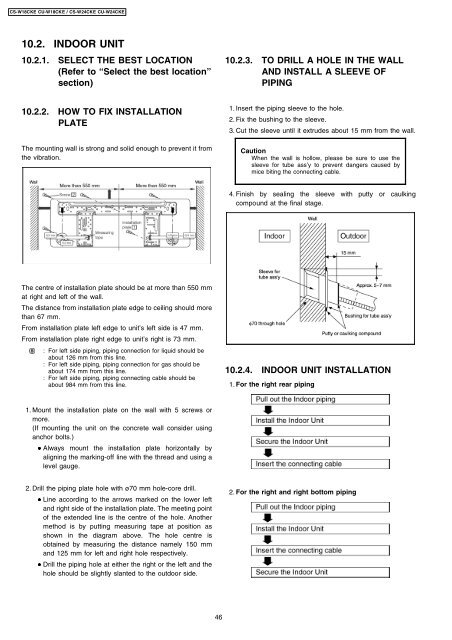
10.2. INDOOR UNIT<br />
10.2.1. SELECT THE BEST LOCATION<br />
(Refer to “Select the best location”<br />
section)<br />
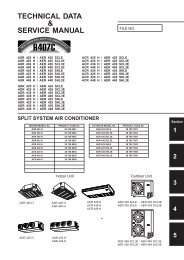
10.2.2. HOW TO FIX INSTALLATION<br />
PLATE<br />
The mounting wall is strong and solid enough to prevent it from<br />
the vibration.<br />
The centre of installation plate should be at more than 550 mm<br />
at right and left of the wall.<br />
The distance from installation plate edge to ceiling should more<br />
than 67 mm.<br />
From installation plate left edge to unit’s left side is 47 mm.<br />
From installation plate right edge to unit’s right is 73 mm.<br />
: For left side piping, piping connection for liquid should be<br />
about 126 mm from this line.<br />
: For left side piping, piping connection for gas should be<br />
about 174 mm from this line.<br />
: For left side piping, piping connecting cable should be<br />
about 984 mm from this line.<br />
1. Mount the installation plate on the wall with 5 screws or<br />
more.<br />
(If mounting the unit on the concrete wall consider using<br />
anchor bolts.)<br />
• • Always mount the installation plate horizontally by<br />
aligning the marking-off line with the thread and using a<br />
level gauge.<br />
2. Drill the piping plate hole with ø70 mm hole-core drill.<br />
• • Line according to the arrows marked on the lower left<br />
and right side of the installation plate. The meeting point<br />
of the extended line is the centre of the hole. Another<br />
method is by putting measuring tape at position as<br />
shown in the diagram above. The hole centre is<br />
obtained by measuring the distance namely 150 mm<br />
and 125 mm for left and right hole respectively.<br />
• • Drill the piping hole at either the right or the left and the<br />
hole should be slightly slanted to the outdoor side.<br />
46<br />
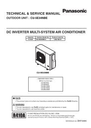
10.2.3. TO DRILL A HOLE IN THE WALL<br />
AND INSTALL A SLEEVE OF<br />
PIPING<br />
1. Insert the piping sleeve to the hole.<br />
2. Fix the bushing to the sleeve.<br />
3. Cut the sleeve until it extrudes about 15 mm from the wall.<br />
Caution<br />
When the wall is hollow, please be sure to use the<br />
sleeve for tube ass’y to prevent dangers caused by<br />
mice biting the connecting cable.<br />
4. Finish by sealing the sleeve with putty or caulking<br />
compound at the final stage.<br />
10.2.4. INDOOR UNIT INSTALLATION<br />
1. For the right rear piping<br />
2. For the right and right bottom piping