technical data & service manual split system air conditioner
technical data & service manual split system air conditioner
technical data & service manual split system air conditioner

Create successful ePaper yourself
Turn your PDF publications into a flip-book with our unique Google optimized e-Paper software.
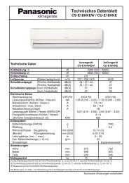
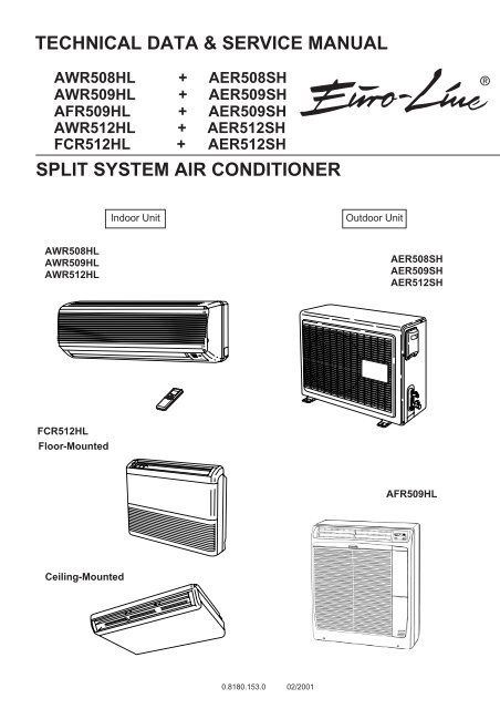
TECHNICAL DATA & SERVICE MANUAL<br />
AWR508HL + AER508SH<br />
AWR509HL + AER509SH<br />
AFR509HL + AER509SH<br />
AWR512HL + AER512SH<br />
FCR512HL + AER512SH<br />
SPLIT SYSTEM AIR CONDITIONER<br />
AWR508HL<br />
AWR509HL<br />
AWR512HL<br />
FCR512HL<br />
Floor-Mounted<br />
Ceiling-Mounted<br />
Indoor Unit Outdoor Unit<br />
0.8180.153.0 02/2001<br />
AER508SH<br />
AER509SH<br />
AER512SH<br />
AFR509HL<br />
®
Important!<br />
Please Read Before Starting<br />
This <strong>air</strong> conditioning <strong>system</strong> meets strict safety and<br />
operating standards. As the installer or <strong>service</strong> person,<br />
it is an important part of your job to install or <strong>service</strong> the<br />
<strong>system</strong> so it operates safely and efficiently.<br />
For safe installation and trouble-free operation, you<br />
must:<br />
●Carefully read this instruction booklet before<br />
beginning.<br />
●Follow each installation or rep<strong>air</strong> step exactly as<br />
shown.<br />
●Observe all local, state, and national electrical codes.<br />
●Pay close attention to all warning and caution notices<br />
given in this <strong>manual</strong>.<br />
If Necessary, Get Help<br />
This symbol refers to a hazard or<br />
unsafe practice which can result<br />
in severe personal injury or<br />
death.<br />
This symbol refers to a hazard or<br />
unsafe practice which can result<br />
in personal injury or product or<br />
property damage.<br />
These instructions are all you need for most installation<br />
sites and maintenance conditions. If you require help<br />
for a special problem, contact our sales/<strong>service</strong> outlet<br />
or your certified dealer for additional instructions.<br />
In Case of Improper Installation<br />
The manufacturer shall in no way be responsible for<br />
improper installation or maintenance <strong>service</strong>, including<br />
failure to follow the instructions in this document.<br />
Special Precautions<br />
WARNING<br />
WARNING<br />
CAUTION<br />
When Wiring<br />
ELECTRICAL SHOCK CAN CAUSE<br />
SEVERE PERSONAL INJURY OR<br />
DEATH. ONLY A QUALIFIED,<br />
EXPERIENCED ELECTRICIAN SHOULD<br />
ATTEMPT TO WIRE THIS SYSTEM.<br />
• Do not supply power to the unit until all wiring and<br />
tubing are completed or reconnected and checked.<br />
• Highly dangerous electrical voltages are used in this<br />
<strong>system</strong>. Carefully refer to the wiring diagram and<br />
these instructions when wiring. Improper connections<br />
and inadequate grounding can cause accidental<br />
injury or death.<br />
• Ground the unit following local electrical codes.<br />
• Connect all wiring tightly. Loose wiring may cause<br />
overheating at connection points and a possible fire<br />
hazard.<br />
i<br />
When Transporting<br />
Be careful when picking up and moving the indoor and<br />
outdoor units. Get a partner to help, and bend your<br />
knees when lifting to reduce strain on your back. Sharp<br />
edges or thin aluminum fins on the <strong>air</strong> <strong>conditioner</strong> can<br />
cut your fingers.<br />
When Installing…<br />
…In a Ceiling or Wall<br />
Make sure the ceiling/wall is strong enough to hold the<br />
unit’s weight. It may be necessary to construct a strong<br />
wood or metal frame to provide added support.<br />
…In a Room<br />
Properly insulate any tubing run inside a room to<br />
prevent “sweating” that can cause dripping and water<br />
damage to walls and floors.<br />
…In Moist or Uneven Locations<br />
Use a raised concrete pad or concrete blocks to<br />
provide a solid, level foundation for the outdoor unit.<br />
This prevents water damage and abnormal vibration.<br />
…In an Area with High Winds<br />
Securely anchor the outdoor unit down with bolts and a<br />
metal frame. Provide a suitable <strong>air</strong> baffle.<br />
…In a Snowy Area (for Heat Pump-type Systems)<br />
Install the outdoor unit on a raised platform that is<br />
higher than drifting snow. Provide snow vents.<br />
When Connecting Refrigerant Tubing<br />
• Use the flare method for connecting tubing.<br />
• Apply refrigerant lubricant to the matching surfaces<br />
of the flare and union tubes before connecting them,<br />
then tighten the nut with a torque wrench for a leakfree<br />
connection.<br />
• Check carefully for leaks before starting the test run.<br />
When Servicing<br />
• Turn the power off at the main power box (mains)<br />
before opening the unit to check or rep<strong>air</strong> electrical<br />
parts and wiring.<br />
• Keep your fingers and clothing away from any<br />
moving parts.<br />
• Clean up the site after you finish, remembering to<br />
check that no metal scraps or bits of wiring have<br />
been left inside the unit being <strong>service</strong>d.<br />
Others<br />
CAUTION<br />
• Ventilate any enclosed areas when installing or<br />
testing the refrigeration <strong>system</strong>. Escaped refrigerant<br />
gas, on contact with fire or heat, can produce<br />
dangerously toxic gas.<br />
• Confirm upon completing installation that no<br />
refrigerant gas is leaking. If escaped gas comes in<br />
contact with a stove, gas water heater, electric room<br />
heater or other heat source, it can produce<br />
dangerously toxic gas.
Table of Contents<br />
1 OPERATING RANGE 1<br />
2 SPECIFICATIONS<br />
2-1 Unit Specification 2<br />
2-2 Major Component Specifications 7<br />
2-3 Other Component Specifications 15<br />
3 DIMENSIONAL DATA 17<br />
4 REFRIGERANT FLOW DIAGRAM 19<br />
5 PERFORMANCE DATA<br />
5-1 Performance Charts 21<br />
5-2 Air Throw Distance Chart 24<br />
5-3 Cooling Capacity 28<br />
5-4 Heating Capacity 33<br />
6 ELECTRICAL DATA<br />
6-1 Electrical Characteristic 34<br />
6-2 Electric Wiring Diagrams 38<br />
7 INSTALLATION INSTRUCTIONS<br />
7-1 Installation Site Selection 42<br />
7-2 Remote Control Unit Installation Position 44<br />
7-3 Recommended Wire Length and Diameter 45<br />
8 FUNCTION<br />
8-1 Room Temperature Control 46<br />
8-2 Dry Operation 48<br />
8-3 Automatic Switching between Cooling and Heating 48<br />
8-4 Freeze prevention 49<br />
8-5 Overload Prevention 50<br />
8-6 Cold Draft Prevention 51<br />
8-7 Defrosting Operation 52<br />
9 REFRIGERANT R407C:SPECIAL PRECAUTION WHEN SERVICING UNIT<br />
9-1 Characteristics of new refrigerant R407c 54<br />
9-2 Checklist before servicing 54<br />
9-3 Tools specifically for R407c 55<br />
9-4 For tubing installation procedures 55<br />
9-5 In case of compressor malfunction 56<br />
9-6 In case refrigerant is leaking 58<br />
9-7 Charging additional refrigerant 60<br />
9-8 Retro-fitting existing <strong>system</strong>s 60<br />
10 TROUBLESHOOTING<br />
10-1 Check before and after troubleshooting 61<br />
10-2 Air Conditioner Does not operate 62<br />
10-3 Some Parts of Air Conditioner does not operate 66<br />
10-4 Air Conditioner Operates, but abnormalities are observed 68<br />
10-5 If a sensor is defective 70<br />
Page
11 CHECKING ELECTRICAL COMPONENTS<br />
11-1 Measurements of insulation resistance 71<br />
11-2 Checking continuity of fuse on PCB ass’y 72<br />
11-3 Checking motor capacitor 72<br />
12 DISASSEMBLY PROCEDURE FOR INDOOR UNIT<br />
12-1 Removing <strong>air</strong> intake grille 73<br />
12-2 Removing side panels 74<br />
12-3 Access and removal of electrical components box 74<br />
12-4 Removing flap motor 75<br />
12-5 Removing evaporator 75<br />
12-6 Removing fan and fan motor 77<br />
APPENDIX Instructions <strong>manual</strong> 78
1. OPERATING RANGE<br />
Cooling<br />
Heating<br />
Temperature Indoor Air Intake Temp. Outdoor Air Intake Temp.<br />
Maximum 32°C D.B. / 23°C W.B. 43°C D.B.<br />
Minimum 19°C D.B. / 14°C W.B. 19°C D.B.<br />
Maximum 27°C D.B. 24°C D.B. / 18°C W.B.<br />
Minimum 16°C D.B. – 8°C D.B. / – 9°C W.B.<br />
1
2. SPECIFICATIONS<br />
2-1. Unit Specifications<br />
Indoor Unit AWR508HL<br />
Outdoor Unit AER508SH<br />
Power Source 220–240V ~ 50Hz<br />
Voltage rating 230 V<br />
Performance Cooling Heating<br />
Capacity kW 2.30 2.6<br />
BTU/h 7,843 8,696<br />
Air circulation (High) m 3 /h 430<br />
Moisture removal (High) Liters/h 0.6 —<br />
Electrical Rating Cooling Heating<br />
Available voltage range V 198 ~ 264<br />
Running amperes A 3.7 3.6<br />
Power input W 820 390<br />
Power factor % 94 96<br />
C.O.P. W/W 2.9 3.4<br />
Compressor locked rotor amperes A 20 20<br />
Features<br />
Controls / Temperature control Microprocessor / I.C. thermostat<br />
Control unit Wireless remote control unit<br />
Timer ON/OFF 24 hours & Daily program,1-hour OFF<br />
Fan speeds Indoor / Outdoor 3 and Auto / 1(Hi)<br />
Airflow direction (Indoor) Horizontal Manual<br />
Vertical Auto<br />
Air filter Washable, Anti-Mold<br />
Compressor Rotary (Hermetic)<br />
Refrigerant / Amount charged at shipment g R407c / 770<br />
Refrigerant control Capillary tube<br />
Operation sound Indoor : Hi / Me / Lo dB-A 37 / 32 / 31 37 / 32 / 31<br />
Outdoor : Hi dB-A 43 45<br />
Refrigerant tubing connections Flare type<br />
Max. allowable tubing length at shipment m 7.5<br />
Refrigerant Narrow tube mm (in.) 6.35(1/4)<br />
tube diameter Wide tube mm (in.) 9.52(3/8)<br />
Refrigerant tube kit / Accessories Optional / Air Clean Filter<br />
Dimensions & Weight Indoor Unit Outdoor Unit<br />
Unit dimensions Height mm 270 540<br />
Width mm 805 700<br />
Depth mm 177 265<br />
Package dimensions Height mm 243 568<br />
Width mm 855 815<br />
Depth mm 332 343<br />
Weight Net kg 8.0 35.0<br />
Shipping kg 10.0 38.0<br />
Shipping volume m 3<br />
0.07 0.16<br />
Remarks:<br />
Rating conditions are:<br />
Cooling : Indoor <strong>air</strong> temperature 27°C D.B. / 19°C W.B.<br />
Outdoor <strong>air</strong> temperature 35°C D.B. / 24°C W.B.<br />
Heating : Indoor <strong>air</strong> temperature 20°C D.B.<br />
Outdoor <strong>air</strong> temperature 7°C D.B. / 6°C W.B.<br />
2<br />
DATA SUBJECT TO CHANGE WITHOUT NOTICE.
Indoor Unit AWR509HL<br />
Outdoor Unit AER509SH<br />
Power Source 220–240V ~ 50Hz<br />
Voltage rating 230 V<br />
Performance Cooling Heating<br />
Capacity kW 2.65 3.5<br />
BTU/h 9,037 11,93<br />
Air circulation (High) m 3 /h 430<br />
Moisture removal (High) Liters/h 0.8 —<br />
Electrical Rating Cooling Heating<br />
Available voltage range V 198 ~ 264<br />
Running amperes A 4.7 4.6<br />
Power input W 1030 1050<br />
Power factor % 95 96<br />
C.O.P. W/W 2.6 3.4<br />
Compressor locked rotor amperes A 24 24<br />
Features<br />
Controls / Temperature control Microprocessor / I.C. thermostat<br />
Control unit Wireless remote control unit<br />
Timer ON/OFF 24 hours & Daily program,1-hour OFF<br />
Fan speeds Indoor / Outdoor 3 and Auto / 1(Hi)<br />
Airflow direction (Indoor) Horizontal Manual<br />
Vertical Auto<br />
Air filter Washable, Anti-Mold<br />
Compressor Rotary (Hermetic)<br />
Refrigerant / Amount charged at shipment g R407c / 990<br />
Refrigerant control Capillary tube<br />
Operation sound Indoor : Hi / Me / Lo dB-A 37 / 32 / 31 37 / 32 / 31<br />
Outdoor : Hi dB-A 43 45<br />
Refrigerant tubing connections Flare type<br />
Max. allowable tubing length at shipment m 7.5<br />
Refrigerant Narrow tube mm (in.) 6.35(1/4)<br />
tube diameter Wide tube mm (in.) 9.52(3/8)<br />
Refrigerant tube kit / Accessories Optional / Air Clean Filter<br />
Dimensions & Weight Indoor Unit Outdoor Unit<br />
Unit dimensions Height mm 270 540<br />
Width mm 805 700<br />
Depth mm 177 265<br />
Package dimensions Height mm 243 568<br />
Width mm 855 815<br />
Depth mm 332 343<br />
Weight Net kg 8.0 36.0<br />
Shipping kg 10.0 39.0<br />
Shipping volume m 3<br />
0.07 0.16<br />
Remarks:<br />
Rating conditions are:<br />
Cooling : Indoor <strong>air</strong> temperature 27°C D.B. / 19°C W.B.<br />
Outdoor <strong>air</strong> temperature 35°C D.B. / 24°C W.B.<br />
Heating : Indoor <strong>air</strong> temperature 20°C D.B.<br />
Outdoor<strong>air</strong>temperature7°CD.B./6°CW.B.<br />
3<br />
DATA SUBJECT TO CHANGE WITHOUT NOTICE.
Indoor Unit AWR512HL<br />
Outdoor Unit AER512SH<br />
Power Source 220–240V ~ 50Hz<br />
Voltage rating 230 V<br />
Performance Cooling Heating<br />
Capacity kW 3.30 4.10<br />
BTU/h 11,424 13,98<br />
Air circulation (High) m 3 /h 430<br />
Moisture removal (High) Liters/h 1.3 —<br />
Electrical Rating Cooling Heating<br />
Available voltage range V 198 ~ 264<br />
Running amperes A 6.2 6.6<br />
Power input W 1,300 1,400<br />
Power factor % 95 94<br />
C.O.P. W/W 2.5 3.0<br />
Compressor locked rotor amperes A 33 33<br />
Features<br />
Controls / Temperature control Microprocessor / I.C. thermostat<br />
Control unit Wireless remote control unit<br />
Timer ON/OFF 24 hours & Daily program,1-hour OFF<br />
Fan speeds Indoor / Outdoor 3 and Auto / 1(Hi)<br />
Airflow direction (Indoor) Horizontal Manual<br />
Vertical Auto<br />
Air filter Washable, Anti-Mold<br />
Compressor Rotary (Hermetic)<br />
Refrigerant / Amount charged at shipment g R407c / 1,150<br />
Refrigerant control Capillary tube<br />
Operation sound Indoor : Hi / Me / Lo dB-A 39 / 35 / 33 39 / 35 / 33<br />
Outdoor : Hi dB-A 45 47<br />
Refrigerant tubing connections Flare type<br />
Max. allowable tubing length at shipment m 7.5<br />
Refrigerant Narrow tube mm (in.) 6.35(1/4)<br />
tube diameter Wide tube mm (in.) 12.7(1/2)<br />
Refrigerant tube kit / Accessories Optional / Air Clean Filter<br />
Dimensions & Weight Indoor Unit Outdoor Unit<br />
Unit dimensions Height mm 270 540<br />
Width mm 805 700<br />
Depth mm 177 265<br />
Package dimensions Height mm 243 568<br />
Width mm 855 815<br />
Depth mm 332 343<br />
Weight Net kg 8.0 38.0<br />
Shipping kg 10.0 41.0<br />
Shipping volume m 3<br />
0.07 0.16<br />
Remarks:<br />
Rating conditions are:<br />
Cooling : Indoor <strong>air</strong> temperature 27°C D.B. / 19°C W.B.<br />
Outdoor <strong>air</strong> temperature 35°C D.B. / 24°C W.B.<br />
Heating : Indoor <strong>air</strong> temperature 20°C D.B.<br />
Outdoor <strong>air</strong> temperature 7°C D.B. / 6°C W.B.<br />
4<br />
DATA SUBJECT TO CHANGE WITHOUT NOTICE.
Indoor Unit AFR509HL<br />
Outdoor Unit AER509SH<br />
Power Source 220–240V ~ 50Hz<br />
Voltage rating 230 V<br />
Performance Cooling Heating<br />
Capacity kW 2.65 3.5<br />
BTU/h 9,037 11,93<br />
Air circulation (High) m 3 /h 370<br />
Moisture removal (High) Liters/h 1.3 —<br />
Electrical Rating Cooling Heating<br />
Available voltage range V 198 ~ 264<br />
Running amperes A 4.7 4.6<br />
Power input W 1030 1050<br />
Power factor % 95 96<br />
C.O.P. W/W 2.6 3.4<br />
Compressor locked rotor amperes A 24 24<br />
Features<br />
Controls / Temperature control Microprocessor / I.C. thermostat<br />
Control unit Wireless remote control unit<br />
Timer ON/OFF 24 hours & Daily program,1-hour OFF<br />
Fan speeds Indoor / Outdoor 3 and Auto / 1(Hi)<br />
Airflow direction (Indoor) Horizontal Manual<br />
Vertical Manual<br />
Air filter Washable, Anti-Mold<br />
Compressor Rotary (Hermetic)<br />
Refrigerant / Amount charged at shipment g R407c / 990<br />
Refrigerant control Capillary tube<br />
Operation sound Indoor : Hi / Me / Lo dB-A 37 / 32 / 31 37 / 32 / 31<br />
Outdoor : Hi dB-A 43 45<br />
Refrigerant tubing connections Flare type<br />
Max. allowable tubing length at shipment m 7.5<br />
Refrigerant Narrow tube mm (in.) 6.35(1/4)<br />
tube diameter Wide tube mm (in.) 9.52(3/8)<br />
Refrigerant tube kit / Accessories Optional / Air Clean Filter<br />
Dimensions & Weight Indoor Unit Outdoor Unit<br />
Unit dimensions Height mm 700 540<br />
Width mm 560 700<br />
Depth mm 200 265<br />
Package dimensions Height mm 770 568<br />
Width mm 620 815<br />
Depth mm 265 343<br />
Weight Net kg 18 36.0<br />
Shipping kg 20 37.0<br />
Shipping volume m 3<br />
0.07 0.16<br />
Remarks:<br />
Rating conditions are:<br />
Cooling : Indoor <strong>air</strong> temperature 27°C D.B. / 19°C W.B.<br />
Outdoor <strong>air</strong> temperature 35°C D.B. / 24°C W.B.<br />
Heating : Indoor <strong>air</strong> temperature 20°C D.B.<br />
Outdoor<strong>air</strong>temperature7°CD.B./6°CW.B.<br />
5<br />
DATA SUBJECT TO CHANGE WITHOUT NOTICE.
Indoor Unit FCR512HL<br />
Outdoor Unit AER512SH<br />
Power Source 220–240V ~ 50Hz<br />
Voltage rating 230 V<br />
Performance Cooling Heating<br />
Capacity kW 3.30 4.10<br />
BTU/h 11,424 14,98<br />
Air circulation (High) m 3 /h 700<br />
Moisture removal (High) Liters/h 1.8 —<br />
Electrical Rating Cooling Heating<br />
Available voltage range V 198 ~ 264<br />
Running amperes A 6.2 6.6<br />
Power input W 1300 1400<br />
Power factor % 95 94<br />
C.O.P. W/W 2.5 3.0<br />
Compressor locked rotor amperes A 33 33<br />
Features<br />
Controls / Temperature control Microprocessor / I.C. thermostat<br />
Control unit Wireless remote control unit<br />
Timer ON/OFF 24 hours & Daily program,1-hour OFF<br />
Fan speeds Indoor / Outdoor 3 and Auto / 1(Hi)<br />
Airflow direction (Indoor) Horizontal Manual<br />
Vertical Auto<br />
Air filter Washable, Anti-Mold<br />
Compressor Rotary (Hermetic)<br />
Refrigerant / Amount charged at shipment g<br />
R407c /1150<br />
Refrigerant control Capillary tube<br />
Operation sound Indoor : Hi / Me / Lo dB-A 44 / 40 / 35 44 / 40 / 35<br />
Outdoor : Hi dB-A 45 47<br />
Refrigerant tubing connections Flare type<br />
Max. allowable tubing length at shipment m 7.5<br />
Refrigerant Narrow tube mm (in.) 6.35(1/4)<br />
tube diameter Wide tube mm (in.) 12.7(1/2)<br />
Refrigerant tube kit / Accessories Optional / Air Clean Filter<br />
Dimensions & Weight Indoor Unit Outdoor Unit<br />
Unit dimensions Height mm 680 540<br />
Width mm 900 700<br />
Depth mm 190 265<br />
Package dimensions Height mm 813 568<br />
Width mm 1,011 815<br />
Depth mm 296 343<br />
Weight Net kg 23.5 38.0<br />
Shipping kg 30.0 41.0<br />
Shipping volume m 3<br />
0.24 0.16<br />
Remarks:<br />
Rating conditions are:<br />
Cooling : Indoor <strong>air</strong> temperature 27°C D.B. / 19°C W.B.<br />
Outdoor <strong>air</strong> temperature 35°C D.B. / 24°C W.B.<br />
Heating : Indoor <strong>air</strong> temperature 20°C D.B.<br />
Outdoor <strong>air</strong> temperature 7°C D.B. / 6°C W.B.<br />
6<br />
DATA SUBJECT TO CHANGE WITHOUT NOTICE.
2-2. Major Component Specifications<br />
2-2-1. Indoor Unit<br />
Indoor Unit AWR508HL<br />
Controller PCB<br />
Part No. POW-K78EH(A), POW-K8EH(B)<br />
Controls Microprocessor<br />
Control circuit fuse 250 V 3.15 A<br />
Remote Control Unit RCS-8HPS3E<br />
Fan & Fan Motor<br />
Type Cross-flow<br />
Q'ty ... Dia. and length mm 1 ... ø95 / L617<br />
Fan motor model ... Q'ty KFV4Q-11H5P-S ... 1<br />
No. of poles ... rpm (230 V, High) 4 ... 1,130<br />
Nominal output W 10<br />
Coil resistance (Ambient temp. 20°C) Ω BRN-WHT : 561.8<br />
VLT-WHT : 197.4<br />
VLT-ORG : 63.4<br />
YEL-ORG : 155.7<br />
YEL-PNK : 115.9<br />
Safety devices Type Internal fuse<br />
Operating temp. Open °C 145±2<br />
Close —<br />
Run capacitor µF 0.6<br />
VAC 440<br />
Flap Motor<br />
Type Stepping motor<br />
Model MP24GA1<br />
Rating DC 12 V<br />
Coil resistance (Ambient temp. 25°C) Ω WHT – BLU (respectively 4 wires) : 380 ± 7%<br />
Heat Exch. Coil<br />
Coil Aluminum plate fin / Copper tube<br />
Rows 2<br />
Fin pitch mm 1.2<br />
Face area m 2<br />
0.130<br />
7<br />
DATA SUBJECT TO CHANGE WITHOUT NOTICE.
Indoor Unit AWR509HL<br />
Controller PCB<br />
Part No. POW-K78EH(A), POW-K8EH(B)<br />
Controls Microprocessor<br />
Control circuit fuse 250 V 3.15 A<br />
Remote Control Unit RCS-8HPS3E<br />
Fan & Fan Motor<br />
Type Cross-flow<br />
Q'ty ... Dia. and length mm 1 ... ø95 / L617<br />
Fan motor model ... Q'ty KFV4Q-11H5P-S ... 1<br />
No. of poles ... rpm (230 V, High) 4 ... 1,190<br />
Nominal output W 10<br />
Coil resistance (Ambient temp. 20°C) Ω BRN-WHT : 561.8<br />
VLT-WHT : 197.4<br />
VLT-ORG : 63.4<br />
YEL-ORG : 155.7<br />
YEL-PNK : 115.9<br />
Safety devices Type Internal fuse<br />
Operating temp. Open °C 145±2<br />
Close —<br />
Run capacitor µF 0.8<br />
VAC 440<br />
Flap Motor<br />
Type Stepping motor<br />
Model MP24GA1<br />
Rating DC 12 V<br />
Coil resistance (Ambient temp. 25°C) Ω WHT – BLU (respectively 4 wires) : 380 ± 7%<br />
Heat Exch. Coil<br />
Coil Aluminum plate fin / Copper tube<br />
Rows 2<br />
Fin pitch mm 1.4<br />
Face area m 2<br />
0.130<br />
8<br />
DATA SUBJECT TO CHANGE WITHOUT NOTICE.
Indoor Unit AWR512HL<br />
Controller PCB<br />
Part No. POW-K128EH(A), POW-K8EH(B)<br />
Controls Microprocessor<br />
Control circuit fuse 250 V 3.15 A<br />
Remote Control Unit RCS-8HPS3E<br />
Fan & Fan Motor<br />
Type Cross-flow<br />
Q'ty ... Dia. and length mm 1 ... ø95 / L617<br />
Fan motor model ... Q'ty KFV4Q-11H5P-S ... 1<br />
No. of poles ... rpm (230 V, High) 4 ... 1,230<br />
Nominal output W 10<br />
Coil resistance (Ambient temp. 20°C) Ω BRN-WHT : 561.8<br />
VLT-WHT : 197.4<br />
VLT-ORG : 63.4<br />
YEL-ORG : 155.7<br />
YEL-PNK : 115.9<br />
Safety devices Type Internal fuse<br />
Operating temp. Open °C 145±2<br />
Close —<br />
Run capacitor µF 1.0<br />
VAC 440<br />
Flap Motor<br />
Type Stepping motor<br />
Model MP24GA1<br />
Rating DC 12 V<br />
Coil resistance (Ambient temp. 25°C) Ω WHT – BLU (respectively 4 wires) : 380 ± 7%<br />
Heat Exch. Coil<br />
Coil Aluminum plate fin / Copper tube<br />
Rows 2<br />
Fin pitch mm 1.4<br />
Face area m 2<br />
0.130<br />
9<br />
DATA SUBJECT TO CHANGE WITHOUT NOTICE.
Indoor Unit AFR509HL<br />
Controller PCB<br />
Part No. POW-K96GHS(C)<br />
Controls Microprocessor<br />
Control circuit fuse 250 V 3 A<br />
Remote Control Unit RCS-8HPS3E<br />
Fan & Fan Motor<br />
Type Cross-flow<br />
Q'ty ... Dia. and length mm 1 ... ø100/C410<br />
Fan motor model ... Q'ty KR35406M01527 ... 1<br />
No. of poles ... rpm (230 V, High) 4 ... 1,130<br />
Nominal output W 27<br />
Coil resistance (Ambient temp. 20°C) Ω GRY-WHT : 545-630<br />
WHT-VLT : 192-105<br />
VLT-YEL : 62-71<br />
YEL-BRN : 780-900<br />
Safety devices Type Internal fuse<br />
Operating temp. Open °C 150±10<br />
Close —<br />
Run capacitor µF 0.6<br />
VAC 400<br />
Heat Exch. Coil<br />
Coil Aluminum plate fin / Copper tube<br />
Rows 2<br />
Fin pitch mm 1.4<br />
Face area m 2<br />
0.185<br />
10<br />
DATA SUBJECT TO CHANGE WITHOUT NOTICE.
Indoor Unit FCR512HL<br />
Controller PCB<br />
Part No. POW-K126GHS-(C)<br />
Controls Microprocessor<br />
Control circuit fuse 250 V 3.15 A<br />
Remote Control Unit RCS-6HPS3E<br />
Fan & Fan Motor<br />
Type Cross-flow<br />
Q'ty ... Dia. and length mm 2 ... ø130 / L180<br />
Fan motor model ... Q'ty K48407-M01596 ... 1<br />
No. of poles ... rpm (230 V, High) 4 ... 1,160<br />
Nominal output W 20<br />
Coil resistance (Ambient temp. 20°C) Ω GRY-WHT : 314±7%<br />
WHT-PNK : 444±7%<br />
WHT-VLT : 98.9±7%<br />
VLT-ORG : 98.9±7%<br />
ORG-YEL : 223±7%<br />
Safety devices Type Internal protector<br />
Operating temp. Open °C 145±5<br />
Close Automatic reclosing<br />
Run capacitor µF 1.5<br />
VAC 440<br />
Flap Motor<br />
Model M2LJ24ZE31<br />
Rating AC 208 / 230 V, 50 / 60 Hz<br />
No. of poles ... rpm 8 ... 2.5 / 3.0<br />
Nominal output W 3 / 2.5<br />
Coil resistance (Ambient temp. 20°C) kΩ 16.45 ± 15%<br />
Heat Exch. Coil<br />
Coil Aluminum plate fin / Copper tube<br />
Rows 2<br />
Fin pitch mm 1.8<br />
Face area m 2 0.192<br />
11<br />
DATA SUBJECT TO CHANGE WITHOUT NOTICE.
2-2-2. Outdoor Unit<br />
Outdoor Unit AER508SH<br />
Controller PCB POW-C96GH<br />
Compressor<br />
Type Rotary (Hermetic)<br />
Compressor model C-RN75H5A 80225245F<br />
Nominal output W 750<br />
Compressor oil ... Amount cc ROTARY OIL ... 470<br />
Coil resistance (Ambient temp. 25°C) Ω C–R : 3.45<br />
C–S : 8.79<br />
Safety devices Type External(OLR A) External(OLR T)<br />
Overload relay MRA38082-3229 CS-7C115<br />
Operating temp. Open °C 135±5 115±3<br />
Close °C 69±11 95±5<br />
Operating amp.(Ambient temp. 25°C) Trip in 6 to 16 sec. at 14A —<br />
Run capacitor µF 20<br />
VAC 400<br />
Crank case heater —<br />
Fan & Fan Motor<br />
Type Propeller<br />
Q'ty ... Dia. 1 ... ø370<br />
Fan motor model ... Q'ty K35610M01723 ... 1<br />
No. of poles ... rpm (230 V, High) 6 ... 810<br />
Nominal output W 20<br />
Coil resistance (Ambient temp. 20°C) Ω WHT-BRN : 341 - 392<br />
WHT-PNK : 476 - 548<br />
— —<br />
Safety devices Type Internal fuse<br />
Operating temp. Open °C 145±2<br />
Close °C —<br />
Run capacitor µF 1.5<br />
VAC 450<br />
Heat Exch. Coil<br />
Coil Aluminum plate fin / Copper tube<br />
Rows 1<br />
Fin pitch mm 1.3<br />
Face area m 2<br />
0.353<br />
External Finish Acrylic baked-on enamel finish<br />
12<br />
DATA SUBJECT TO CHANGE WITHOUT NOTICE.
Outdoor Unit AER509SH<br />
Controller PCB POW-C96GH<br />
Compressor<br />
Type Rotary (Hermetic)<br />
Compressor model C-RN90H5B 80228345-S<br />
Nominal output W 900<br />
Compressor oil ... Amount cc ROTARY OIL ... 470<br />
Coil resistance (Ambient temp. 25°C) Ω C–R : 3.07<br />
C–S : 6.69<br />
Safety devices Type External(OLR A) External(OLR T)<br />
Overload relay MRA38066-3229 CS-7C115<br />
Operating temp. Open °C 145±5 115±5<br />
Close °C 69±11 95±10<br />
Operating amp.(Ambient temp. 25°C) Trip in 6 to 16 sec. at 18A —<br />
Run capacitor µF 25<br />
VAC 400<br />
Crank case heater —<br />
Fan & Fan Motor<br />
Type Propeller<br />
Q'ty ... Dia. 1 ... ø370<br />
Fan motor model ... Q'ty K35610M01723 ... 1<br />
No. of poles ... rpm (230 V, High) 6 ... 810<br />
Nominal output W 20<br />
Coil resistance (Ambient temp. 20°C) Ω WHT-BRN : 341 - 392<br />
WHT-PNK : 476 - 548<br />
— —<br />
Safety devices Type Internal fuse<br />
Operating temp. Open °C 145±2<br />
Close °C —<br />
Run capacitor µF 1.5<br />
VAC 450<br />
Heat Exch. Coil<br />
Coil Aluminum plate fin / Copper tube<br />
Rows 1<br />
Fin pitch mm 1.2<br />
Face area m 2<br />
0.353<br />
External Finish Acrylic baked-on enamel finish<br />
13<br />
DATA SUBJECT TO CHANGE WITHOUT NOTICE.
Outdoor Unit AER512SH<br />
Controller PCB POW-C96GH<br />
Compressor<br />
Type Rotary (Hermetic)<br />
Compressor model C-RN110H5B 80235645B<br />
Nominal output W 1,100<br />
Compressor oil ... Amount cc FV68S ... 550<br />
Coil resistance (Ambient temp. 25°C) Ω C–R : 1.962<br />
C–S : 5.38<br />
Safety devices Type External(OLR A) External(OLR T)<br />
Overload relay MRA38065-3229 CS-7C115<br />
Operating temp. Open °C 135±5 115±3<br />
Close °C 69±11 95±5<br />
Operating amp.(Ambient temp. 25°C) Trip in 6 to 16 sec. at 14A —<br />
Run capacitor µF 25<br />
VAC 450<br />
Crank case heater —<br />
Fan & Fan Motor<br />
Type Propeller<br />
Q'ty ... Dia. 1 ... ø370<br />
Fan motor model ... Q'ty K35610M01722 ... 1<br />
No. of poles ... rpm (230 V, High) 6 ... 830<br />
Nominal output W 21<br />
Coil resistance (Ambient temp. 20°C) Ω BRN-WHT : 250 - 288<br />
WHT-YEL : 344 - 396<br />
Safety devices Type Internal protector<br />
Operating temp. Open °C 130±8<br />
Close °C Automatic reclosing<br />
Run capacitor µF 1.5<br />
VAC 450<br />
Heat Exch. Coil<br />
Coil Aluminum plate fin / Copper tube<br />
Rows 2<br />
Fin pitch mm 1.4<br />
Face area m 2<br />
0.333<br />
External Finish Acrylic baked-on enamel finish<br />
14<br />
DATA SUBJECT TO CHANGE WITHOUT NOTICE.
2-3. Other Component Specifications<br />
Indoor Unit AWR508HL<br />
AWR509HL<br />
AWR512HL<br />
Transformer (TR) ATR-J105<br />
Rating Primary AC 230V, 50/60Hz<br />
Outdoor Unit AER508SH<br />
AER509SH<br />
AER512SH<br />
Secondary 19V, 0.526A<br />
Capacity 10VA<br />
Coil resistance Ω(at 21°C) Primary (WHT – WHT): 205 ± 10%<br />
Thermostat (Defrost thermo. 23D) TRS02-12MSR<br />
Operating temp. °C ON 12 ± 2<br />
4-way Valve (SC) LB60012 (Coil), VH7100C (Valve)<br />
Coil rating AC 220/240V, 50Hz, 6W<br />
Coil resistance Ω(at 20°C) 1,740 ± 7%<br />
15<br />
Secondary (BRN – BRN): 2.0 ± 10%<br />
Thermal cut-off temp. 150°C<br />
Thermistor (Coil sensor) DTN-TKS131B<br />
Resistance kΩ 0°C 15.0 ± 2%<br />
Thermistor (Room sensor) DTN-TKS134B<br />
Resistance kΩ 25°C 5.0 ± 3%<br />
Power Relay (PR) DFU24D1F<br />
Coil rating DC 24V<br />
Coil resistance Ω(at 20°C) 650 ± 10%<br />
Contact rating AC 250V, 20A<br />
Diff. 8 deg. below<br />
<br />
4-way Valve (SC)<br />
(Solenoid coil) LB60012 (Coil), V26-110B (Valve)<br />
Coil rating AC 220/240V, 50Hz, 6W<br />
Coil resistance Ω(at 20°C) 1,740 ± 7%<br />
PTC Thermistor (TH) TDK 101YV<br />
Resistance Ω(at 25°C) 100 ± 20%<br />
<br />
Indoor Unit AFR509HL<br />
Thermistor (Room sensor TH2) DHKTEC-35-S6N<br />
Resistance kΩ -20°C 10 ± 5%<br />
Thermistor (Coil sensor TH1) DHPBC-41ES-14N<br />
Resistance kΩ –20°C 40.1 ± 5%<br />
Transformer (TR) ATR-H85<br />
Rating Primary AC 235V, 50Hz<br />
Secondary 11V, 0.727A<br />
Capacity 8VA<br />
Coil resistance Ω (at 21°C) Primary (WHT – WHT): 214 ± 10%<br />
16<br />
-10° 7.9 ± 5%<br />
-20°C 6.3 ± 5%<br />
-10°C 5.0 ± 5%<br />
–10°C 24.4 ± 5%<br />
0°C 15.3 ± 5%<br />
-10°C 9.9 ± 5%<br />
Secondary (BRN – BRN): 1.58 ± 10%<br />
Thermal cut-off temp. 145°C, 2A, 250V<br />
Indoor Unit FCR512HL<br />
Thermistor (Room sensor TH2) KTEC-35-S6<br />
Resistance kΩ 10°C 10.0 ± 4% 30°C 4.0 ± 4%<br />
15°C 7.9 ± 4% 35°C 3.3 ± 4%<br />
20°C 6.3 ± 4% 40°C 2.7 ± 4%<br />
25°C 5.0 ± 4% 50°C 1.8 ± 4%<br />
Thermistor (Coil sensor TH1) PBC-41E-S14<br />
Resistance kΩ –20°C 40.1 ± 5% 20°C 6.5 ± 5%<br />
–10°C 24.4 ± 5% 30°C 4.4 ± 5%<br />
0°C 15.3 ± 5% 40°C 3.0 ± 5%<br />
10°C 9.9 ± 5% 50°C 2.1 ± 5%<br />
Transformer (TR) ATR-J105<br />
Rating Primary AC 230V, 50/60Hz<br />
Secondary 19V, 0.526A<br />
Capacity 10VA<br />
Coil resistance Ω (at 21°C) Primary (WHT – WHT): 205 ± 10%<br />
Secondary (BRN – BRN): 2.0 ± 10%<br />
Thermal cut-off temp. 150°C
3. DIMENSIONAL DATA<br />
Indoor Unit AWR508HL<br />
AWR509HL<br />
AWR512HL<br />
41.0<br />
99.5<br />
Drain hose ø18<br />
Center of tubing<br />
hole (2 places)<br />
805 177<br />
17<br />
58.5<br />
Narrow tube ø6.35 (1/4")<br />
41.0 270<br />
Wide tube ø9.52 (3/8") AWR508,AWR509<br />
Wide tube ø12.7 (1/2") AWR512<br />
Remote control unit<br />
61<br />
172.5<br />
18.5<br />
Unit : mm
Outdoor Unit AER508SH<br />
AER509SH<br />
AER512SH<br />
4 – ø12 holes<br />
470<br />
Air intake<br />
Air discharge<br />
700<br />
116<br />
18<br />
294<br />
15<br />
320<br />
540<br />
Wide tube <strong>service</strong> valve<br />
ø9.52 (3/8")<br />
ø12.7 (1/2")<br />
Narrow tube <strong>service</strong> valve<br />
ø6.35 (1/4")<br />
255<br />
170<br />
AER508,AER509<br />
AER512<br />
103 57<br />
Unit : mm
4. REFRIGERANT FLOW DIAGRAM<br />
Indoor Unit AWR508HL Outdoor Unit AER508SH<br />
Indoor unit Outdoor unit<br />
Heat exchanger<br />
Wide tube<br />
O.D.<br />
ø9.52 mm<br />
(3/8 ")<br />
Narrow tube<br />
O.D.<br />
ø6.35 mm<br />
(1/4")<br />
Wide tube<br />
Accumulator<br />
<strong>service</strong><br />
valve<br />
Muffler<br />
19<br />
4-way<br />
valve<br />
Narrow<br />
tube<br />
<strong>service</strong><br />
Capillary tube<br />
valve<br />
Capillary tube<br />
Strainer<br />
Indoor Unit AWR509HL<br />
AFR509HL<br />
Outdoor Unit AER509SH<br />
Indoor unit Outdoor unit<br />
Heat exchanger<br />
Wide tube<br />
O.D.<br />
ø9.52 mm<br />
(3/8 ")<br />
Narrow tube<br />
O.D.<br />
ø6.35 mm<br />
(1/4")<br />
4-way<br />
valve<br />
Check<br />
valve<br />
Wide tube<br />
Accumulator<br />
<strong>service</strong><br />
valve<br />
Muffler<br />
Narrow<br />
tube<br />
<strong>service</strong><br />
Capillary tube<br />
valve<br />
Strainer<br />
Check<br />
valve<br />
Compressor<br />
Heat exchanger<br />
Compressor<br />
Heat exchanger<br />
Cooling cycle<br />
Heating cycle<br />
Cooling cycle<br />
Heating cycle
Indoor Unit AWR512HL<br />
FCR512HL<br />
Outdoor Unit AER512SH<br />
Indoor unit Outdoor unit<br />
Insulation of Refrigerant Tubing<br />
IMPORTANT<br />
Heat exchanger<br />
Because capillary tubing is used in the outdoor unit, both the<br />
wide and narrow tubes of this <strong>air</strong> <strong>conditioner</strong> become cold. To<br />
prevent heat loss and wet floors due to dripping of<br />
condensation, both tubes must be well insulated with a<br />
proper insulation material. The thickness of the insulation<br />
should be a min. 8 mm.<br />
CAUTION<br />
Wide tube<br />
O.D.<br />
ø12.7 mm<br />
(1/2 ")<br />
Narrow tube<br />
O.D.<br />
ø6.35 mm<br />
(1/4")<br />
Wide tube<br />
<strong>service</strong><br />
valve<br />
Narrow<br />
tube<br />
<strong>service</strong><br />
valve<br />
Muffler<br />
Strainer<br />
After a tube has been insulated,<br />
never try to bend it into a narrow<br />
curve because it can cause the tube<br />
to break or crack.<br />
20<br />
Accumulator<br />
4-way<br />
valve<br />
Capillary tube<br />
Check<br />
valve<br />
Thickness:<br />
Min. 8 mm<br />
Wide tube<br />
Compressor<br />
Heat exchanger<br />
Insulation<br />
Cooling cycle<br />
Heating cycle<br />
Narrow tube<br />
Thickness:<br />
Min. 8 mm
5. PERFORMANCE DATA<br />
5-1. Performance charts<br />
Indoor Unit AWR508HL<br />
Outdoor Unit AER508SH<br />
NOTE<br />
Low pressure at wide tube <strong>service</strong> valve MPa (kgf/cm 2G)<br />
■ Cooling Characteristics ■ Heating Characteristics<br />
Operating current (A)<br />
10<br />
9<br />
8<br />
7<br />
6<br />
5<br />
4<br />
3<br />
2<br />
1.38 (13)<br />
1.28 (12)<br />
1.18 (11)<br />
1.08 (10)<br />
0.98 ( 9 )<br />
0.89 ( 8 )<br />
0.79 ( 7 )<br />
0.69 ( 6 )<br />
0.59 ( 5 )<br />
0.49 ( 4 )<br />
0.39 ( 3 )<br />
Indoor inlet <strong>air</strong><br />
D.B. temp. (°C)<br />
1<br />
25 30 35 40 45 50<br />
Outdoor inlet <strong>air</strong> D.B. temp. (°C)<br />
Indoor inlet <strong>air</strong><br />
D.B. temp. (°C)<br />
32<br />
27<br />
19.4<br />
32<br />
27<br />
19.4<br />
25 30 35 40 45 50<br />
Outdoor inlet <strong>air</strong> D.B. temp. (°C)<br />
High pressure at wide tube <strong>service</strong> valve MPa (kgf/cm 2G)<br />
21<br />
Operating current (A)<br />
10<br />
9<br />
8<br />
7<br />
6<br />
5<br />
4<br />
3<br />
2<br />
1<br />
2.95 (30)<br />
2.85 (28)<br />
2.65 (26)<br />
2.46 (24)<br />
2.26 (22)<br />
2.06 (20)<br />
1.87 (18)<br />
1.67 (16)<br />
1.47 (14)<br />
1.28 (12)<br />
1.08 (10)<br />
Indoor inlet <strong>air</strong><br />
D.B. temp. (°C)<br />
–5 0 5 7 10 15 20 25<br />
Outdoor inlet <strong>air</strong> D.B. temp. (°C)<br />
Indoor inlet <strong>air</strong><br />
D.B. temp. (°C)<br />
–5 0 5 7 10 15 20 25<br />
Outdoor inlet <strong>air</strong> D.B. temp. (°C)<br />
Overload prevention operates to protect the <strong>air</strong> <strong>conditioner</strong> when outdoor ambient temperature reaches extremely<br />
high in heating mode. (Refer to “8-5 Overload prevention”)<br />
● ...... Points of Rating condition<br />
Black dots in above charts indicate the following rating conditions.<br />
Cooling: Indoor <strong>air</strong> temperature 27°C D.B./19°C W.B. Heating:Indoor <strong>air</strong> temperature 20°C D.B.<br />
Outdoor <strong>air</strong> temperature 35°C D.B./24°C W.B. Outdoor <strong>air</strong> temperature 7°C D.B./6°C W.B.<br />
27<br />
20<br />
15<br />
27<br />
20<br />
15
Indoor Unit AWR509HL AFR509HL<br />
Outdoor Unit AER509SH<br />
NOTE<br />
Low pressure at wide tube <strong>service</strong> valve MPa (kgf/cm 2G)<br />
■ Cooling Characteristics ■ Heating Characteristics<br />
Operating current (A)<br />
10<br />
9<br />
8<br />
7<br />
6<br />
5<br />
4<br />
3<br />
2<br />
1.38 (13)<br />
1.28 (12)<br />
1.18 (11)<br />
1.08 (10)<br />
0.98 ( 9 )<br />
0.89 ( 8 )<br />
0.79 ( 7 )<br />
0.69 ( 6 )<br />
0.59 ( 5 )<br />
0.49 ( 4 )<br />
0.39 ( 3 )<br />
Indoor inlet <strong>air</strong><br />
D.B. temp. (°C)<br />
1<br />
25 30 35 40 45 50<br />
Outdoor inlet <strong>air</strong> D.B. temp. (°C)<br />
Indoor inlet <strong>air</strong><br />
D.B. temp. (°C)<br />
32<br />
27<br />
19.4<br />
32<br />
27<br />
19.4<br />
25 30 35 40 45 50<br />
Outdoor inlet <strong>air</strong> D.B. temp. (°C)<br />
High pressure at wide tube <strong>service</strong> valve MPa (kgf/cm 2G)<br />
22<br />
Operating current (A)<br />
10<br />
9<br />
8<br />
7<br />
6<br />
5<br />
4<br />
3<br />
2<br />
1<br />
2.95 (30)<br />
2.85 (28)<br />
2.65 (26)<br />
2.46 (24)<br />
2.26 (22)<br />
2.06 (20)<br />
1.87 (18)<br />
1.67 (16)<br />
1.47 (14)<br />
1.28 (12)<br />
1.08 (10)<br />
Indoor inlet <strong>air</strong><br />
D.B. temp. (°C)<br />
–5 0 5 7 10 15 20 25<br />
Outdoor inlet <strong>air</strong> D.B. temp. (°C)<br />
Indoor inlet <strong>air</strong><br />
D.B. temp. (°C)<br />
–5 0 5 7 10 15 20 25<br />
Outdoor inlet <strong>air</strong> D.B. temp. (°C)<br />
Overload prevention operates to protect the <strong>air</strong> <strong>conditioner</strong> when outdoor ambient temperature reaches extremely<br />
high in heating mode. (Refer to “8-5 Overload prevention”)<br />
● ...... Points of Rating condition<br />
Black dots in above charts indicate the following rating conditions.<br />
Cooling: Indoor <strong>air</strong> temperature 27°C D.B./19°C W.B. Heating:Indoor <strong>air</strong> temperature 20°C D.B.<br />
Outdoor <strong>air</strong> temperature 35°C D.B./24°C W.B. Outdoor <strong>air</strong> temperature 7°C D.B./6°C W.B.<br />
27<br />
20<br />
15<br />
27<br />
20<br />
15
Indoor Unit AWR512HL FCR512HL<br />
Outdoor Unit AER512SH<br />
NOTE<br />
Low pressure at wide tube <strong>service</strong> valve MPa (kgf/cm 2G)<br />
■ Cooling Characteristics ■ Heating Characteristics<br />
Operating current (A)<br />
12<br />
11<br />
10<br />
9<br />
8<br />
7<br />
6<br />
5<br />
4<br />
1.38 (13)<br />
1.28 (12)<br />
1.18 (11)<br />
1.08 (10)<br />
0.98 ( 9 )<br />
0.89 ( 8 )<br />
0.79 ( 7 )<br />
0.69 ( 6 )<br />
0.59 ( 5 )<br />
0.49 ( 4 )<br />
Indoor inlet <strong>air</strong><br />
D.B. temp. (°C)<br />
3<br />
25 30 35 40 45 50<br />
Outdoor inlet <strong>air</strong> D.B. temp. (°C)<br />
Indoor inlet <strong>air</strong><br />
D.B. temp. (°C)<br />
32<br />
27<br />
19.4<br />
32<br />
27<br />
19.4<br />
0.39 ( 3 )<br />
25 30 35 40 45 50<br />
Outdoor inlet <strong>air</strong> D.B. temp. (°C)<br />
High pressure at wide tube <strong>service</strong> valve MPa (kgf/cm 2G)<br />
23<br />
Operating current (A)<br />
12<br />
11<br />
10<br />
9<br />
8<br />
7<br />
6<br />
5<br />
4<br />
3<br />
2.95 (30)<br />
2.85 (28)<br />
2.65 (26)<br />
2.46 (24)<br />
2.26 (22)<br />
2.06 (20)<br />
1.87 (18)<br />
1.67 (16)<br />
1.47 (14)<br />
1.28 (12)<br />
1.08 (10)<br />
Indoor inlet <strong>air</strong><br />
D.B. temp. (°C)<br />
–5 0 5 7 10 15 20 25<br />
Outdoor inlet <strong>air</strong> D.B. temp. (°C)<br />
Indoor inlet <strong>air</strong><br />
D.B. temp. (°C)<br />
–5 0 5 7 10 15 20<br />
Outdoor inlet <strong>air</strong> D.B. temp. (°C)<br />
Overload prevention operates to protect the <strong>air</strong> <strong>conditioner</strong> when outdoor ambient temperature reaches extremely<br />
high in heating mode. (Refer to “8-5 Overload prevention”)<br />
● ...... Points of Rating condition<br />
Black dots in above charts indicate the following rating conditions.<br />
Cooling: Indoor <strong>air</strong> temperature 27°C D.B./19°C W.B. Heating: Indoor <strong>air</strong> temperature 20°C D.B.<br />
Outdoor <strong>air</strong> temperature 35°C D.B./24°C W.B. Outdoor <strong>air</strong> temperature 7°C D.B./6°C W.B.<br />
25<br />
27<br />
20<br />
15<br />
27<br />
20<br />
15
5-2. Air Throw Distance Chart<br />
Indoor Unit AWR508HL<br />
Cooling<br />
Room <strong>air</strong> temp. : 27°C<br />
Fan speed : High<br />
Axis <strong>air</strong> velocity (m/s)<br />
Vertical distance (m)<br />
Heating<br />
0<br />
1<br />
2<br />
3<br />
4<br />
Room <strong>air</strong> temp. : 20°C<br />
Fan speed : High<br />
Axis <strong>air</strong> velocity (m/s)<br />
Vertical distance (m)<br />
0<br />
1<br />
2<br />
3<br />
4<br />
1 2 3 4 5 6 7 8 9<br />
Axis <strong>air</strong> velocity<br />
Flap angle<br />
24<br />
Horizontal distance (m)<br />
0°<br />
30°<br />
Horizontal distance (m)<br />
1 2 3 4 5 6 7 8 9<br />
Axis <strong>air</strong> velocity<br />
Flap angle<br />
45°<br />
60°
Indoor Unit AWR509HL<br />
Cooling<br />
Room <strong>air</strong> temp. : 27°C<br />
Fan speed : High<br />
Axis <strong>air</strong> velocity (m/s)<br />
Vertical distance (m)<br />
Heating<br />
Axis <strong>air</strong> velocity (m/s)<br />
Vertical distance (m)<br />
0<br />
1<br />
2<br />
3<br />
4<br />
Room <strong>air</strong> temp. : 20°C<br />
Fan speed : High<br />
0<br />
1<br />
2<br />
3<br />
4<br />
1 2 3 4 5 6 7 8 9<br />
Axis <strong>air</strong> velocity<br />
Flap angle<br />
1 2 3 4 5 6 7 8 9<br />
Axis <strong>air</strong> velocity<br />
Flap angle<br />
25<br />
Horizontal distance (m)<br />
0°<br />
30°<br />
Horizontal distance (m)<br />
45°<br />
60°
Indoor Unit AWR512HL<br />
Cooling<br />
Room <strong>air</strong> temp. : 27°C<br />
Fan speed : High<br />
Axis <strong>air</strong> velocity (m/s)<br />
Vertical distance (m)<br />
Heating<br />
Axis <strong>air</strong> velocity (m/s)<br />
Vertical distance (m)<br />
0<br />
1<br />
2<br />
3<br />
4<br />
Room <strong>air</strong> temp. : 20°C<br />
Fan speed : High<br />
0<br />
1<br />
2<br />
3<br />
4<br />
Horizontal distance (m)<br />
1 2 3 4 5 6 7 8 9<br />
Axis <strong>air</strong> velocity<br />
0°<br />
Flap angle<br />
30°<br />
1 2 3 4 5 6 7 8 9<br />
Axis <strong>air</strong> velocity<br />
45°<br />
Flap angle<br />
60°<br />
26<br />
Horizontal distance (m)
Indoor Unit FCR512HL<br />
Ceiling mounted<br />
Cooling<br />
Room <strong>air</strong> temp. : 27°C<br />
Fan speed : High<br />
Axis <strong>air</strong> velocity (m/s)<br />
Vertical distance (m)<br />
Heating<br />
Horizontal distance (m)<br />
0<br />
0<br />
1 2 3 4 5 6 7<br />
1<br />
2<br />
3<br />
Room <strong>air</strong> temp. : 20°C<br />
Fan speed : High<br />
Axis <strong>air</strong> velocity (m/s)<br />
Vertical distance (m)<br />
Horizontal distance (m)<br />
0<br />
0<br />
1 2 3 4 5 6 7<br />
1<br />
2<br />
3<br />
27<br />
Axis <strong>air</strong> verocity<br />
Flap angle<br />
30°<br />
45°<br />
Axis <strong>air</strong> verocity<br />
Flap angle<br />
80°<br />
60°
5-3. Cooling Capacity<br />
Indoor Unit AWR508HL<br />
Outdoor Unit AER508SH<br />
230V Single Phase 50Hz<br />
RATING CAPACITY 2.30 kW<br />
AIR FLOW RATE 430 m 3 /h<br />
EVAPORATOR CONDENSER<br />
ENT. TEMP. °C OUTDOOR AMBIENT TEMP. °C<br />
W.B. D.B. 20 25 30 35 40 45<br />
TC 2.32 2.22 2.12 2.02 1.89 1.74<br />
CM 0.53 0.58 0.62 0.66 0.69 0.72<br />
21 SHC 1.63 1.58 1.53 1.48 1.42 1.35<br />
15 23 SHC 1.84 1.79 1.74 1.70 1.64 1.57<br />
25 SHC 2.06 2.01 1.96 1.91 1.85 1.74<br />
27 SHC 2.28 2.22 2.12 2.02 1.89 1.74<br />
29 SHC 2.32 2.22 2.12 2.02 1.89 1.74<br />
31 SHC 2.32 2.22 2.12 2.02 1.89 1.74<br />
TC 2.49 2.38 2.27 2.16 2.03 1.87<br />
CM 0.55 0.59 0.63 0.68 0.71 0.74<br />
21 SHC 1.40 1.35 1.30 1.26 1.20 1.13<br />
17 23 SHC 1.62 1.57 1.52 1.47 1.42 1.35<br />
25 SHC 1.84 1.79 1.74 1.69 1.63 1.56<br />
27 SHC 2.05 2.00 1.95 1.91 1.85 1.78<br />
29 SHC 2.27 2.22 2.17 2.12 2.03 1.87<br />
31 SHC 2.49 2.38 2.27 2.16 2.03 1.87<br />
TC 2.65 2.53 2.42 # 2.30 2.16 1.99<br />
CM 0.56 0.61 0.65 0.70 0.73 0.77<br />
21 SHC 1.17 1.12 1.07 1.03 0.97 0.90<br />
19 23 SHC 1.39 1.34 1.29 1.24 1.19 1.12<br />
25 SHC 1.60 1.55 1.51 1.46 1.40 1.33<br />
27 SHC 1.82 1.77 1.72 1.67 1.62 1.55<br />
29 SHC 2.04 1.99 1.94 1.89 1.83 1.77<br />
31 SHC 2.25 2.20 2.16 2.11 2.05 1.98<br />
TC 2.80 2.68 2.56 2.44 2.29 2.11<br />
CM 0.58 0.63 0.67 0.72 0.75 0.79<br />
23 SHC 1.15 1.10 1.06 1.01 0.95 0.89<br />
21 25 SHC 1.37 1.32 1.27 1.23 1.17 1.10<br />
27 SHC 1.59 1.54 1.49 1.44 1.39 1.32<br />
29 SHC 1.80 1.75 1.71 1.66 1.60 1.54<br />
31 SHC 2.02 1.97 1.92 1.88 1.82 1.75<br />
TC 2.98 2.85 2.71 2.56 2.40 2.23<br />
CM 0.59 0.64 0.69 0.74 0.77 0.81<br />
23 25 SHC 1.12 1.08 1.03 0.97 0.92 0.86<br />
27 SHC 1.34 1.29 1.24 1.19 1.13 1.08<br />
29 SHC 1.56 1.51 1.46 1.41 1.35 1.29<br />
31 SHC 1.77 1.73 1.68 1.62 1.57 1.51<br />
TC : Total Cooling Capacity (kW)<br />
SHC : Sensible Heat Capacity (kW)<br />
CM : Compressor Input (kW)<br />
Rating conditions (#Mark) are<br />
Outdoor Ambient Temp. 35°C D.B.<br />
Indoor Unit Entering Air Temp. 27°C D.B. / 19°C W.B.<br />
28
Indoor Unit AWR509HL<br />
Outdoor Unit AER509SH<br />
230V Single Phase 50Hz<br />
RATING CAPACITY 2.65 kW<br />
AIR FLOW RATE 430 m 3 /h<br />
EVAPORATOR CONDENSER<br />
ENT. TEMP. °C OUTDOOR AMBIENT TEMP. °C<br />
W.B. D.B. 20 25 30 35 40 45<br />
TC 2.67 2.55 2.44 2.32 2.18 2.01<br />
CM 0.67 0.72 0.77 0.83 0.92 1.01<br />
21 SHC 1.80 1.74 1.69 1.63 1.56 1.47<br />
15 23 SHC 2.02 1.96 1.90 1.84 1.77 1.69<br />
25 SHC 2.24 2.18 2.12 2.06 1.99 1.91<br />
27 SHC 2.45 2.39 2.33 2.28 2.18 2.01<br />
29 SHC 2.67 2.55 2.44 2.32 2.18 2.01<br />
31 SHC 2.67 2.55 2.44 2.32 2.18 2.01<br />
TC 2.86 2.74 2.62 2.49 2.34 2.15<br />
CM 0.69 0.74 0.79 0.85 0.94 1.03<br />
21 SHC 1.58 1.52 1.46 1.40 1.34 1.25<br />
17 23 SHC 1.80 1.74 1.68 1.62 1.55 1.47<br />
25 SHC 2.02 1.96 1.90 1.84 1.77 1.68<br />
27 SHC 2.23 2.17 2.11 2.05 1.99 1.90<br />
29 SHC 2.45 2.39 2.33 2.27 2.20 2.12<br />
31 SHC 2.67 2.61 2.55 2.49 2.34 2.15<br />
TC 3.05 2.92 2.78 # 2.65 2.49 2.29<br />
CM 0.71 0.76 0.82 0.88 0.97 1.06<br />
21 SHC 1.35 1.29 1.23 1.17 1.10 1.02<br />
19 23 SHC 1.57 1.51 1.45 1.39 1.32 1.24<br />
25 SHC 1.78 1.72 1.66 1.61 1.54 1.45<br />
27 SHC 2.00 1.94 1.88 1.82 1.75 1.67<br />
29 SHC 2.22 2.16 2.10 2.04 1.97 1.89<br />
31 SHC 2.43 2.37 2.31 2.25 2.19 2.10<br />
TC 3.23 3.09 2.95 2.81 2.64 2.43<br />
CM 0.73 0.79 0.84 0.90 1.00 1.09<br />
23 SHC 1.33 1.27 1.21 1.15 1.09 1.01<br />
21 25 SHC 1.54 1.49 1.43 1.37 1.30 1.22<br />
27 SHC 1.76 1.70 1.64 1.59 1.52 1.44<br />
29 SHC 1.98 1.92 1.86 1.80 1.74 1.65<br />
31 SHC 2.19 2.14 2.08 2.02 1.95 1.87<br />
TC 3.43 3.28 3.12 2.95 2.76 2.57<br />
CM 0.74 0.81 0.86 0.93 1.02 1.12<br />
23 25 SHC 1.29 1.24 1.18 1.11 1.04 0.97<br />
27 SHC 1.51 1.45 1.39 1.33 1.26 1.19<br />
29 SHC 1.73 1.67 1.61 1.55 1.48 1.41<br />
31 SHC 1.94 1.89 1.83 1.76 1.69 1.62<br />
TC : Total Cooling Capacity (kW)<br />
SHC : Sensible Heat Capacity (kW)<br />
CM : Compressor Input (kW)<br />
Rating conditions (#Mark) are<br />
Outdoor Ambient Temp. 35°C D.B.<br />
Indoor Unit Entering Air Temp. 27°C D.B. / 19°C W.B.<br />
29
Indoor Unit AWR512HL<br />
Outdoor Unit AER512SH<br />
230V Single Phase 50Hz<br />
RATING CAPACITY 3.3 kW<br />
AIR FLOW RATE 430 m³/h<br />
EVAPORATOR CONDENSER<br />
ENT.TEMP. °C OUTDOOR AMBIENT TEMP. °C<br />
W.B. D.B. 25 30 35 40 43<br />
TC 3.13 3.03 2.89 2.71 2.50<br />
CM 0.85 0.90 0.97 1.07 1.16<br />
21 SHC 2.14 2.10 2.03 1.94 1.84<br />
23 SHC 2.43 2.38 2.31 2.22 2.12<br />
15 25 SHC 2.71 2.65 2.58 2.50 2.40<br />
27 SHC 2.99 2.93 2.86 2.71 2.50<br />
29 SHC 3.13 3.03 2.89 2.71 2.50<br />
31 SHC 3.13 3.03 2.89 2.71 2.50<br />
TC 3.39 3.26 3.10 2.91 2.68<br />
CM 0.87 0.93 1.00 1.10 1.19<br />
21 SHC 1.88 1.82 1.75 1.66 1.56<br />
23 SHC 2.16 2.09 2.02 1.94 1.84<br />
17 25 SHC 2.44 2.37 2.30 2.22 2.11<br />
27 SHC 2.72 2.65 2.58 2.49 2.39<br />
29 SHC 3.01 2.93 2.86 2.77 2.66<br />
31 SHC 3.29 3.20 3.10 2.91 2.68<br />
TC 3.59 3.47 3.30 3.10 2.86<br />
CM 0.91 0.96 1.03 1.13 1.22<br />
21 SHC 1.57 1.52 1.45 1.36 1.26<br />
23 SHC 1.85 1.80 1.73 1.64 1.54<br />
19 25 SHC 2.12 2.07 2.00 1.92 1.82<br />
27 SHC 2.39 2.35 2.28 2.20 2.09<br />
29 SHC 2.65 2.63 2.55 2.48 2.37<br />
31 SHC 2.93 2.91 2.83 2.75 2.65<br />
TC 3.80 3.67 3.50 3.29 3.03<br />
CM 0.93 0.99 1.06 1.16 1.26<br />
23 SHC 1.55 1.50 1.43 1.34 1.24<br />
21 25 SHC 1.82 1.77 1.71 1.62 1.52<br />
27 SHC 2.09 2.05 1.98 1.90 1.79<br />
29 SHC 2.36 2.32 2.26 2.17 2.07<br />
31 SHC 2.63 2.60 2.53 2.45 2.35<br />
TC 4.06 3.89 3.67 3.44 3.20<br />
CM 0.95 1.01 1.09 1.19 1.29<br />
23 25 SHC 1.52 1.46 1.38 1.29 1.21<br />
27 SHC 1.78 1.73 1.65 1.56 1.48<br />
29 SHC 2.05 2.01 1.93 1.84 1.76<br />
31 SHC 2.34 2.29 2.20 2.12 2.04<br />
TC: TOTAL COOLING CAPACITY kW<br />
SHC: SENSIBLE HEAT CAPACITY kW<br />
CM: COMPRESSOR INPUT kW<br />
RATING CONDITIONS<br />
OUTDOOR AMBIENT TEMPERATURE 35°C D.B.<br />
INDOOR UNIT ENTERING AIR TEMP. 27°C D.B./19°C W.B.<br />
30
Indoor Unit AFR509HL<br />
Outdoor Unit AER509SH<br />
230V Single Phase 50Hz<br />
RATING CAPACITY 2.65 kW<br />
AIR FLOW RATE 370 m 3 /h<br />
EVAPORATOR CONDENSER<br />
ENT. TEMP. °C OUTDOOR AMBIENT TEMP. °C<br />
W.B. D.B. 20 25 30 35 40 45<br />
TC 2.67 2.55 2.44 2.32 2.18 2.01<br />
CM 0.67 0.72 0.77 0.83 0.92 1.01<br />
21 SHC 1.80 1.74 1.69 1.63 1.56 1.47<br />
15 23 SHC 2.02 1.96 1.90 1.84 1.77 1.69<br />
25 SHC 2.24 2.18 2.12 2.06 1.99 1.91<br />
27 SHC 2.45 2.39 2.33 2.28 2.18 2.01<br />
29 SHC 2.67 2.55 2.44 2.32 2.18 2.01<br />
31 SHC 2.67 2.55 2.44 2.32 2.18 2.01<br />
TC 2.86 2.74 2.62 2.49 2.34 2.15<br />
CM 0.69 0.74 0.79 0.85 0.94 1.03<br />
21 SHC 1.58 1.52 1.46 1.40 1.34 1.25<br />
17 23 SHC 1.80 1.74 1.68 1.62 1.55 1.47<br />
25 SHC 2.02 1.96 1.90 1.84 1.77 1.68<br />
27 SHC 2.23 2.17 2.11 2.05 1.99 1.90<br />
29 SHC 2.45 2.39 2.33 2.27 2.20 2.12<br />
31 SHC 2.67 2.61 2.55 2.49 2.34 2.15<br />
TC 3.05 2.92 2.78 # 2.65 2.49 2.29<br />
CM 0.71 0.76 0.82 0.88 0.97 1.06<br />
21 SHC 1.35 1.29 1.23 1.17 1.10 1.02<br />
19 23 SHC 1.57 1.51 1.45 1.39 1.32 1.24<br />
25 SHC 1.78 1.72 1.66 1.61 1.54 1.45<br />
27 SHC 2.00 1.94 1.88 1.82 1.75 1.67<br />
29 SHC 2.22 2.16 2.10 2.04 1.97 1.89<br />
31 SHC 2.43 2.37 2.31 2.25 2.19 2.10<br />
TC 3.23 3.09 2.95 2.81 2.64 2.43<br />
CM 0.73 0.79 0.84 0.90 1.00 1.09<br />
23 SHC 1.33 1.27 1.21 1.15 1.09 1.01<br />
21 25 SHC 1.54 1.49 1.43 1.37 1.30 1.22<br />
27 SHC 1.76 1.70 1.64 1.59 1.52 1.44<br />
29 SHC 1.98 1.92 1.86 1.80 1.74 1.65<br />
31 SHC 2.19 2.14 2.08 2.02 1.95 1.87<br />
TC 3.43 3.28 3.12 2.95 2.76 2.57<br />
CM 0.74 0.81 0.86 0.93 1.02 1.12<br />
23 25 SHC 1.29 1.24 1.18 1.11 1.04 0.97<br />
27 SHC 1.51 1.45 1.39 1.33 1.26 1.19<br />
29 SHC 1.73 1.67 1.61 1.55 1.48 1.41<br />
31 SHC 1.94 1.89 1.83 1.76 1.69 1.62<br />
TC : Total Cooling Capacity (kW)<br />
SHC : Sensible Heat Capacity (kW)<br />
CM : Compressor Input (kW)<br />
Rating conditions (#Mark) are<br />
Outdoor Ambient Temp. 35°C D.B.<br />
Indoor Unit Entering Air Temp. 27°C D.B. / 19°C W.B.<br />
31
Indoor Unit FCR512HL<br />
Outdoor Unit AER512SH<br />
240V Single Phase 50Hz<br />
RATING CAPACITY 3.35 kW<br />
AIR FLOW RATE 700 m 3 /h<br />
EVAPORATOR CONDENSER<br />
ENT. TEMP. °C OUTDOOR AMBIENT TEMP. °C<br />
W.B. D.B. 20 25 30 35 40 45<br />
TC 3.38 3.23 3.08 2.93 2.76 2.54<br />
CM 0.90 0.97 1.04 1.12 1.22 1.32<br />
21 SHC 2.42 2.35 2.28 2.21 2.13 2.03<br />
15 23 SHC 2.77 2.70 2.63 2.56 2.48 2.38<br />
25 SHC 3.11 3.04 2.97 2.91 2.76 2.54<br />
27 SHC 3.38 3.23 3.08 2.93 2.76 2.54<br />
29 SHC 3.38 3.23 3.08 2.93 2.76 2.54<br />
31 SHC 3.38 3.23 3.08 2.93 2.76 2.54<br />
TC 3.62 3.46 3.31 3.15 2.96 2.72<br />
CM 0.92 1.00 1.07 1.15 1.25 1.35<br />
21 SHC 2.07 1.99 1.92 1.86 1.77 1.67<br />
17 23 SHC 2.41 2.34 2.27 2.20 2.12 2.02<br />
25 SHC 2.76 2.69 2.62 2.55 2.47 2.37<br />
27 SHC 3.10 3.03 2.96 2.89 2.81 2.71<br />
29 SHC 3.45 3.38 3.31 3.15 2.96 2.72<br />
31 SHC 3.62 3.46 3.31 3.15 2.96 2.72<br />
TC 3.85 3.69 3.52 # 3.35 3.15 2.90<br />
CM 0.95 1.03 1.10 1.18 1.29 1.39<br />
21 SHC 1.69 1.62 1.56 1.49 1.41 1.31<br />
19 23 SHC 2.04 1.97 1.90 1.83 1.75 1.65<br />
25 SHC 2.39 2.32 2.25 2.18 2.10 2.00<br />
27 SHC 2.73 2.66 2.59 2.53 2.45 2.35<br />
29 SHC 3.08 3.01 2.94 2.87 2.79 2.69<br />
31 SHC 3.43 3.36 3.29 3.22 3.14 2.90<br />
TC 4.08 3.91 3.73 3.55 3.34 3.07<br />
CM 0.98 1.06 1.13 1.22 1.32 1.43<br />
23 SHC 1.67 1.60 1.53 1.46 1.39 1.29<br />
21 25 SHC 2.01 1.94 1.88 1.81 1.73 1.63<br />
27 SHC 2.36 2.29 2.22 2.16 2.08 1.98<br />
29 SHC 2.71 2.64 2.57 2.50 2.42 2.33<br />
31 SHC 3.05 2.98 2.92 2.85 2.77 2.67<br />
TC 4.33 4.15 3.95 3.73 3.49 3.25<br />
CM 1.00 1.09 1.16 1.25 1.36 1.46<br />
23 25 SHC 1.62 1.55 1.49 1.41 1.33 1.25<br />
27 SHC 1.97 1.90 1.83 1.76 1.67 1.59<br />
29 SHC 2.31 2.25 2.18 2.10 2.02 1.94<br />
31 SHC 2.66 2.59 2.52 2.45 2.37 2.29<br />
TC : Total Cooling Capacity (kW)<br />
SHC : Sensible Heat Capacity (kW)<br />
CM : Compressor Input (kW)<br />
32
5-4. Heating Capacity<br />
Heating capacity ratio (%)<br />
120<br />
110<br />
100<br />
90<br />
80<br />
70<br />
60<br />
50<br />
40<br />
30<br />
20<br />
10<br />
0<br />
–8<br />
NOTE<br />
–5 0 5 7 10 15<br />
Outdoor temperature (°C DB)<br />
1) … Point of Rating condition<br />
Black dot in the chart indicate the following rating condition.<br />
Indoor : 20°C D.B.<br />
Outdoor : 7°C D.B. / 6°C W.B.<br />
2) Above characteristics indicate instantaneous operation, which does not take into<br />
consideration defrost operation.<br />
3) Fan speed : High<br />
4) Because this <strong>air</strong> <strong>conditioner</strong> heats a room by drawing in the heat of the outside<br />
<strong>air</strong> (heat pump <strong>system</strong>), the heating efficiency will fall off when the outdoor<br />
temperature is very low. If sufficient heat cannot be obtained with this <strong>air</strong><br />
<strong>conditioner</strong>, use another heating appliance in conjunction with it.<br />
33
6. ELECTRICAL DATA<br />
6-1. Electrical Characteristics<br />
Indoor Unit AWR508HL<br />
Outdoor Unit AER508SH<br />
COOLING<br />
Indoor Unit Outdoor Unit Complete Unit<br />
Fan Motor Fan Motor Compressor<br />
Performance at 230V 1-phase 50Hz<br />
Rating Conditions Running Amps. A 0.11 0.24 3.35 3.7<br />
Power Input kW 0.025 0.055 0.74 0.82<br />
Full Load Conditions Running Amps. A 0.11 0.24 4.05 4.4<br />
Power Input kW 0.025 0.055 0.86 0.94<br />
Rating Conditions : Indoor Air Temperature 27°C D.B. / 19°C W.B.<br />
Outdoor Air Temperature 35°C D.B.<br />
Full Load Conditions : Indoor Air Temperature 32°C D.B. / 23°C W.B.<br />
Outdoor Air Temperature 43°C D.B.<br />
HEATING<br />
Indoor Unit Outdoor Unit Complete Unit<br />
Fan Motor Fan Motor Compressor<br />
Performance at 230V 1-phase 50Hz<br />
Rating Conditions Running Amps. A 0.11 0.24 3.05 3.4<br />
Power Input kW 0.025 0.055 0.671 0.75<br />
Full Load Conditions Running Amps. A 0.11 0.24 3.65 4.0<br />
Power Input kW 0.025 0.055 0.801 0.88<br />
Rating Conditions : Indoor Air Temperature 20°C D.B.<br />
Outdoor Air Temperature 7°C D.B. / 6°C W.B.<br />
Full Load Conditions : Indoor Air Temperature 27°C D.B.<br />
Outdoor Air Temperature 24°C D.B. / 18°C W.B.<br />
34
Indoor Unit AWR509HL AFR509HL<br />
Outdoor Unit AER509SH<br />
COOLING<br />
Indoor Unit Outdoor Unit Complete Unit<br />
Fan Motor Fan Motor Compressor<br />
Performance at 230V 1-phase 50Hz<br />
Rating Conditions Running Amps. A 0.12 0.24 4.34 4.7<br />
Power Input kW 0.027 0.055 0.948 1.03<br />
Full Load Conditions Running Amps. A 0.12 0.24 5.15 5.5<br />
Power Input kW 0.027 0.055 1.148 1.23<br />
Rating Conditions : Indoor Air Temperature 27°C D.B. / 19°C W.B.<br />
Outdoor Air Temperature 35°C D.B.<br />
Full Load Conditions : Indoor Air Temperature 32°C D.B. / 23°C W.B.<br />
Outdoor Air Temperature 43°C D.B.<br />
HEATING<br />
Indoor Unit Outdoor Unit Complete Unit<br />
Fan Motor Fan Motor Compressor<br />
Performance at 230V 1-phase 50Hz<br />
Rating Conditions Running Amps. A 0.12 0.24 3.85 4.2<br />
Power Input kW 0.027 0.055 0.848 0.93<br />
Full Load Conditions Running Amps. A 0.12 0.24 4.85 5.2<br />
Power Input kW 0.027 0.055 1.058 1.14<br />
Rating Conditions : Indoor Air Temperature 20°C D.B.<br />
Outdoor Air Temperature 7°C D.B. / 6°C W.B.<br />
Full Load Conditions : Indoor Air Temperature 27°C D.B.<br />
Outdoor Air Temperature 24°C D.B. / 18°C W.B.<br />
35
Indoor Unit AWR512HL<br />
Outdoor Unit AER512SH<br />
COOLING<br />
Indoor Unit Outdoor Unit Complete Unit<br />
Fan Motor Fan Motor Compressor<br />
Performance at 230V 1-phase 50Hz<br />
Rating Conditions Running Amps. A 0.13 0.28 5.79 6.2<br />
Power Input kW 0.031 0.062 1.207 1.3<br />
Full Load Conditions Running Amps. A 0.13 0.28 6.79 7.2<br />
Power Input kW 0.031 0.062 1.427 1.52<br />
Rating Conditions : Indoor Air Temperature 27°C D.B. / 19°C W.B.<br />
Outdoor Air Temperature 35°C D.B.<br />
Full Load Conditions : Indoor Air Temperature 32°C D.B. / 23°C W.B.<br />
Outdoor Air Temperature 43°C D.B.<br />
HEATING<br />
Indoor Unit Outdoor Unit Complete Unit<br />
Fan Motor Fan Motor Compressor<br />
Performance at 230V 1-phase 50Hz<br />
Rating Conditions Running Amps. A 0.13 0.28 5.69 6.1<br />
Power Input kW 0.031 0.062 1.227 1.32<br />
Full Load Conditions Running Amps. A 0.13 0.28 7.59 8.0<br />
Power Input kW 0.031 0.062 1.617 1.71<br />
Rating Conditions : Indoor Air Temperature 20°C D.B.<br />
Outdoor Air Temperature 7°C D.B. / 6°C W.B.<br />
Full Load Conditions : Indoor Air Temperature 27°C D.B.<br />
Outdoor Air Temperature 24°C D.B. / 18°C W.B.<br />
36
Indoor Unit FCR512HL<br />
Outdoor Unit AER512SH<br />
COOLING<br />
Indoor Unit Outdoor Unit Complete Unit<br />
Fan Motor Fan Motor Compressor<br />
Performance at 230V ~ 50Hz<br />
Rating Conditions Running Amps. A 0.29 0.32 5.6 6.2<br />
Power Input kW 0.070 0.076 1.154 1.13<br />
Full Load Conditions Running Amps. A 0.29 0.32 6.59 7.2<br />
Power Input kW 0.070 0.076 1.374 1.52<br />
Rating Conditions : Indoor Air Temperature 27°C D.B. / 19°C W.B.<br />
Outdoor Air Temperature 35°C D.B.<br />
Full Load Conditions : Indoor Air Temperature 32°C D.B. / 23°C W.B.<br />
Outdoor Air Temperature 43°C D.B.<br />
HEATING<br />
Indoor Unit Outdoor Unit Complete Unit<br />
Fan Motor Fan Motor Compressor<br />
Performance at 220 – 240V ~ 50Hz<br />
Rating Conditions Running Amps. A 0.29 0.32 5.6 6.2<br />
Power Input kW 0.070 0.076 1.22 1.37<br />
Full Load Conditions Running Amps. A 0.29 0.32 7.7 8.3<br />
Power Input kW 0.070 0.076 1.68 1.83<br />
Rating Conditions : Indoor Air Temperature 20°C D.B.<br />
Outdoor Air Temperature 7°C D.B. / 6°C W.B.<br />
Full Load Conditions : Indoor Air Temperature 27°C D.B.<br />
Outdoor Air Temperature 24°C D.B. / 18°C W.B.<br />
37
6-2. Electric Wiring Diagrams<br />
Indoor Unit AWR508HL<br />
AWR509HL<br />
AWR512HL<br />
38<br />
WARNING<br />
To avoid electrical shock hazard, be sure to<br />
disconnect power before checking, servicing<br />
and/or cleaning any electrical parts.
Indoor Unit FCR512HL<br />
39<br />
WARNING<br />
To avoid electrical shock hazard, be sure to<br />
disconnect power before checking, servicing<br />
and/or cleaning any electrical parts.<br />
.
Outdoor Unit AER508SH<br />
AER509SH<br />
40<br />
WARNING<br />
To avoid electrical shock hazard, be sure to<br />
disconnect power before checking, servicing<br />
and/or cleaning any electrical parts.
Outdoor Unit AER512SH<br />
41<br />
WARNING<br />
To avoid electrical shock hazard, be sure to<br />
disconnect power before checking, servicing<br />
and/or cleaning any electrical parts.
7. INSTALLATION INSTRUCTIONS<br />
7-1. Installation Site Selection<br />
Indoor Unit<br />
WARNING<br />
To prevent abnormal heat<br />
generation and the possibility<br />
of fire, don’t place obstacles,<br />
15cm<br />
min. ,<br />
15cm min.<br />
15cm<br />
min.<br />
INDOOR UNIT<br />
enclosures and grills in front<br />
Front View<br />
of or surrounding the <strong>air</strong><br />
<strong>conditioner</strong> in a way that may<br />
block <strong>air</strong> flow.<br />
Fig.1<br />
AVOID:<br />
● direct sunlight.<br />
● nearby heat sources that may affect performance of<br />
the unit.<br />
● areas where leakage of flammable gas may be<br />
expected.<br />
● places where large amounts of oil mist exist.<br />
DO:<br />
● select an appropriate position from which every<br />
corner of the room can be uniformly <strong>air</strong>-conditioned.<br />
(High on a wall is best)<br />
● select a location that will hold the weight of the unit.<br />
● select a location where tubing and drain pipe have the<br />
shortest run to the outside.<br />
● allow room for operation and maintenance as well as<br />
unrestricted <strong>air</strong> flow around the unit. (Fig. 1)<br />
● install the unit within the maximum elevation<br />
difference (H) above or below the outdoor unit and<br />
within a total tubing length (L) from the outdoor unit as<br />
detailed Table 1 and Fig. 2a.<br />
Table 1<br />
Model<br />
Max. Allowable<br />
Tubing Length at<br />
Shipment (m)<br />
Limit of Tubing<br />
Length (L)<br />
(m)<br />
42<br />
INDOOR<br />
UNIT<br />
Elevation<br />
difference (H)<br />
CAUTION<br />
Fig. 2a<br />
Fig. 2<br />
For stable operation of<br />
the <strong>air</strong> <strong>conditioner</strong>, do<br />
not install wall-mounted<br />
type indoor units under<br />
1.5m from floor level.<br />
Fig. 2b<br />
Limit of Elevation<br />
Difference (H)<br />
(m)<br />
Tubing length (L)<br />
OUTDOOR<br />
UNIT<br />
Minimum height<br />
from floor level<br />
1.5m<br />
* If total tubing length becomes a)7.5 to 15 m , b)7.5 to 20 m (max.), charge additional refrigerant (R407c) by<br />
a)15 g/m or b)25 g/m.<br />
No additional charge of compressor oil is necessary.<br />
Indoor Unit<br />
Floor level<br />
Required Amount of<br />
Additional Refrigerant<br />
(g/m)*<br />
AWR508 AWR509 7.5 15<br />
7 a) 15<br />
AWR512 7.5 20 7 b) 25<br />
Wall
Outdoor Unit<br />
AVOID:<br />
● heat sources, exhaust fans, etc. (Fig. 3)<br />
● damp, humid or uneven locations.<br />
DO:<br />
● choose a place as cool as possible.<br />
● choose a place that is well ventilated.<br />
● allow enough room around the unit for <strong>air</strong><br />
intake/exhaust and possible maintenance.<br />
(Figs. 4b and 4c)<br />
● provide a solid base (concrete block, 10 ✕ 40 cm<br />
beams or equal), a minimum of 10 cm above ground<br />
level to reduce humidity and protect the unit against<br />
possible water damage and decreased <strong>service</strong> life.<br />
(Fig.5b)<br />
● use lug bolts or equal to bolt down unit, reducing<br />
vibration and noise.<br />
Required space around the unit.<br />
Air intake Min. 10 cm<br />
Min.<br />
5 cm<br />
Air discharge<br />
Top Fig. View 4b<br />
Air intake<br />
Concrete<br />
or equal<br />
Top View<br />
About 40 cm<br />
Min.<br />
40 cm<br />
Valve<br />
side<br />
Min. 25 cm<br />
Fig. 5b<br />
43<br />
Outdoor unit<br />
About 10 cm<br />
Hot <strong>air</strong><br />
Obstacle above<br />
Air discharge<br />
2 m<br />
Ground<br />
Side View<br />
Fig. 4c<br />
Fig 4 C<br />
Anchor bolts<br />
(4 pcs.)<br />
Min. 10 cm<br />
NO<br />
2 m<br />
Obstacle<br />
Fig. 3<br />
Fig. 3<br />
Exhaust fan<br />
Heat source
7-2. Remote Control Unit Installation<br />
Position<br />
The remote control unit can be operated from either a<br />
non-fixed position or a wall-mounted position.<br />
To ensure that the <strong>air</strong> <strong>conditioner</strong> operates correctly, do<br />
not install the remote control unit in the following places:<br />
● In direct sunlight<br />
● Behind a curtain or other place where it is covered<br />
● More than 8 m away from the <strong>air</strong> <strong>conditioner</strong><br />
● In the path of the <strong>air</strong> <strong>conditioner</strong>'s <strong>air</strong>stream<br />
● Where it may become extremely hot or cold<br />
● Where it may be subject to electrical or magnetic<br />
interference<br />
Mounting on a Wall<br />
a) Removable mounting<br />
1) Momentarily hold the remote control unit at the<br />
desired mounting position.<br />
2) Confirm that the <strong>air</strong> <strong>conditioner</strong> responds<br />
correctly when you press keys on the remote<br />
control from that position.<br />
3) After confirming correct operation, use a<br />
screwdriver to screw the supplied special<br />
mounting screw into the wall. (Fig.6a)<br />
4) Hang the remote control unit from the mounting<br />
screw.<br />
b) Non-removable mounting<br />
1) Momentarily hold the remote control unit at the<br />
desired mounting position.<br />
2) Confirm that the <strong>air</strong> <strong>conditioner</strong> responds<br />
correctly when you press keys on the remote<br />
control from that position.<br />
3) After confirming correct operation, use a<br />
screwdriver to screw the supplied special<br />
mounting screw into the wall. (Fig.6a)<br />
4) Remove the remote control cover by sliding it<br />
downward.<br />
5) Remove the batteries of the remote control unit.<br />
6) Use a screwdriver to screw the remote control<br />
unit securing screw into the wall through the hole<br />
in the battery compartment. (Fig.6b)<br />
7) Replace the batteries.<br />
8) Again confirm that the remote control unit<br />
operates correctly.<br />
44<br />
Screw<br />
Removable mounting<br />
Fig.6a<br />
Fig.6b<br />
Special<br />
mounting<br />
screw<br />
Non-removable mounting<br />
Wall<br />
Wall
7-3. Recommended Wire Length and Diameter<br />
Regulations on wiring diameter differ from locality to<br />
locality. For field wiring requirements, please refer to<br />
your local electrical codes. Carefully observe these<br />
regulations when carrying out the installation.<br />
Table 2 lists recommended wire lengths and cross<br />
section area for power supply <strong>system</strong>s.<br />
Table 2<br />
Model<br />
Cross Sectional<br />
Area (mm 2 )<br />
(A) Power Supply Wiring Length (m) (B) Power Line (m)<br />
2.5 mm 2<br />
AER508SH 57<br />
AER509SH 21<br />
AER512SH 14<br />
WARNING<br />
WARNING<br />
CAUTION<br />
27<br />
● Be sure to comply with<br />
local codes on running the<br />
wire from the indoor unit to<br />
the outdoor unit (size of<br />
wire and wiring method,<br />
etc.).<br />
● Each wire must be firmly<br />
connected.<br />
● No wire should be allowed<br />
to touch refrigerant tubing,<br />
the compressor, or any<br />
moving part.<br />
To avoid the risk of electric<br />
shock, each <strong>air</strong> <strong>conditioner</strong><br />
unit must be grounded.<br />
● Be sure to connect the<br />
power supply line to the<br />
indoor unit as shown in the<br />
wiring diagram. The<br />
outdoor unit draws its<br />
power from the indoor unit.<br />
45<br />
NOTE<br />
Refer to the WIRING SYSTEM DIAGRAM for the<br />
meaning of "A", "B" and "C" in Table 2.<br />
Power supply<br />
220 – 240 V 50Hz<br />
(C) Control Line (m)<br />
2.5 mm 2 1.0 mm 2<br />
WIRING SYSTEM DIAGRAM<br />
A<br />
Indoor unit<br />
L<br />
N<br />
1<br />
2<br />
3<br />
4<br />
Ground<br />
C<br />
Fuse or Circuit<br />
Breaker Capacity<br />
20 20 10A<br />
B<br />
Outdoor unit<br />
L<br />
N<br />
1<br />
2<br />
3<br />
4
8. FUNCTION<br />
8-1. Room Temperature Control<br />
■ Cooling<br />
● Room temperature control is obtained by cycling the compressor ON and OFF under control of the room<br />
temperature sensor in the remote control unit.<br />
● The room temperature (and other information) is transmitted every 3 minutes by the remote control unit to the<br />
controller in the indoor unit.<br />
set temp.<br />
T+1 °C<br />
T °C<br />
Compressor<br />
Outdoor fan<br />
3 minutes 3 minutes 3 minutes 3 minutes 3 minutes 3 minutes 3 minutes<br />
More than<br />
5 minutes<br />
Thermo.<br />
OFF<br />
Signal from remote control unit<br />
Thermo.<br />
ON<br />
5 minutes<br />
Thermo.<br />
OFF<br />
3 minutes<br />
ON OFF ON OFF ON OFF<br />
ON OFF ON OFF ON OFF<br />
Indoor fan Set speed<br />
Thermo.<br />
ON<br />
Thermo.<br />
ON<br />
● The control circuit will not attempt to turn the compressor ON until the compressor has been OFF for at least<br />
3 minutes. To protect the compressor from stalling out when trying to start against the high side refrigerant<br />
pressure, the control circuit has a built-in automatic time delay to allow the internal pressure to equalize.<br />
● As a protective measure, the control circuit switches the compressor OFF after 5 minutes or more of compressor<br />
operation.<br />
● Thermo. ON : When the room temperature is above T + 1°C (T°C is set temperature).<br />
Compressor ➞ ON<br />
● Thermo. OFF : When the room temperature is equal to or below set temperature T°C.<br />
Compressor ➞ OFF<br />
46<br />
Thermo.<br />
ON<br />
Room temp.<br />
Thermo.<br />
OFF
8-2. Dry Operation (Dehumidification)<br />
● Dry operation uses the ability of the cooling cycle to remove moisture from the <strong>air</strong>, but by running at low level to<br />
dehumidify without greatly reducing the room temperature. The <strong>air</strong> <strong>conditioner</strong> repeats the cycle of turning ON<br />
and OFF automatically as shown in the chart below according to the room temperature.<br />
NOTE<br />
T+2 °C<br />
Set temp. T °C<br />
T–1 °C<br />
Room temp. 15 °C<br />
Room temp.<br />
Cooling operation<br />
*Dry A zone<br />
Compressor : Continuous operation<br />
FMI (indoor fan) : L (low speed) / LL (very low speed) intermittent ventilation<br />
only while the compressor is ON.<br />
*Dry B zone<br />
Compressor : Intermittent operation (ON for 3 minutes and OFF for 9 minutes)<br />
FMI (indoor fan) : L (low speed) / LL (very low speed) intermittent ventilation<br />
only while the compressor is ON.<br />
Monitor zone<br />
Both the indoor and outdoor units stop.<br />
● Intermittent ventilation occurs by switching the indoor fan speed between L ↔ LL.<br />
● Dry operation does not occur when the room temperature is under 15°C, which is the monitor zone.<br />
● When the compressor stops, the indoor fan stops as well.<br />
8-3. Automatic Switching between Cooling and Heating<br />
● When AUTO mode is selected, the microprocessor calculates the difference between the set temperature and<br />
the room temperature, and automatically switches to COOLING or HEATING mode to maintain the desired<br />
temperature.<br />
Room temp. ≥ Set temp. ➞ COOL<br />
Room temp. < Set temp. ➞ HEAT<br />
This means that if the room temperature is higher than or equal to the set temperature, COOLING operation<br />
begins. If the room temperature is lower than the set temperature, HEATING operation begins.<br />
48
8-4. Freeze Prevention (Cooling)<br />
● This function prevents freezing of the indoor heat exchange coil.<br />
● When the compressor has been running for 10 minutes *1) or more and the temperature of the indoor heat<br />
exchange coil falls below –1°C, the control circuit stops the compressor for at least 6 minutes. The compressor<br />
does not start again until the temperature rises above 8°C or 6 minutes has elapsed.<br />
T+1 °C<br />
Set temp. T °C<br />
Indoor heat exch.<br />
coil temp.<br />
–1 °C<br />
Compressor<br />
Indoor fan<br />
Room temp.<br />
More than<br />
10 minutes<br />
ON OFF ON ON OFF ON<br />
Set speed<br />
6 minutes<br />
*1)<br />
More than<br />
*1)<br />
10 minutes<br />
Thermo. OFF<br />
Thermo. ON<br />
More than<br />
6 minutes<br />
Set speed<br />
NOTE<br />
*1) Functionally, compressor running period, or time are of two types, 10 minutes and 6 minutes depending upon<br />
production date.<br />
49
8-5. Overload Prevention (Heating)<br />
● This function prevents overheating of the indoor heat exchange coil.<br />
● When the temperature of the indoor heat exchange coil rises above B°C, and if the indoor fan is L (low speed),<br />
then the fan speed changes from L (low speed) to M (medium speed).<br />
● When the temperature of the indoor heat exchange coil rises above A°C, the outdoor fan stops.<br />
NOTE<br />
Indoor heat<br />
exch. coil<br />
temp. °C<br />
Outdoor fan<br />
Indoor fan<br />
Compressor<br />
A<br />
B<br />
C<br />
D<br />
ON OFF<br />
H or M or L H ➞ H, M ➞ M, L ➞ M<br />
The operation temperature shown as A, B, C and D in the chart differ by models.<br />
AWR508HL AWR509HL AWR512HL<br />
A 50°C 54°C 58°C<br />
B 49°C 52°C 56°C<br />
C 42°C 45°C 50°C<br />
D 39°C 42°C 46°C<br />
50<br />
ON<br />
ON
8-6. Cold Draft Prevention (Heating)<br />
● This function controls indoor fan speed so a strong draft of cold <strong>air</strong> will not blow out before the indoor heat<br />
exchange coil have sufficiently warmed up.<br />
● STANDBY lamp on front of the indoor unit lights up when this function is working.<br />
● when 10 minutes has elapsed,the fan speed is automatically switched to set speed regardless of indoor heat<br />
exchange coil temperature.<br />
NOTE<br />
Indoor heat exch.<br />
coil temp. (°C)<br />
The operation temperature shown as Tc in the chart differ by models.<br />
Tc<br />
Indoor fan<br />
Standby lamp<br />
AWR508HL AWR509HL AWR512HL<br />
Tc 32°C 33°C 34°C<br />
Max. 10minutes<br />
OFF<br />
ON<br />
51<br />
Set speed<br />
OFF
8-7. Defrosting Operation (Heating)<br />
■ Defrosting Flowchart<br />
NO<br />
A<br />
Release of overload prevention<br />
(Outdoor fan operates.)<br />
Outdoor fan is either operated<br />
or stopped for more than 10<br />
minutes.<br />
Is outdoor fan continuously<br />
operating for more than 10<br />
minutes?<br />
YES<br />
Integrated operating time of<br />
compressor is more than 50<br />
minutes.<br />
Temperature of indoor heat<br />
exchanger coil is below Ta+<br />
13°C. (See table below.)<br />
Compressor keeps running for<br />
at least 6 minutes.<br />
NOTE<br />
YES<br />
The values shown as Ta, Tb and Tc<br />
differ according to the models.<br />
*1<br />
*2<br />
*3<br />
Ta<br />
Tb<br />
Tc<br />
AWR508HL<br />
35<br />
48<br />
32<br />
*1<br />
B<br />
Overload<br />
prevention works.<br />
Does outdoor fan<br />
stop?<br />
Indoor heat exchanger coil<br />
temperature drops 0.8°C per<br />
6 minutes and it repeats<br />
3 times in succession.<br />
Continuous operating time of<br />
compressor is more than 20<br />
minutes.<br />
Temperature of outdoor heat<br />
exchange coil is higher than<br />
12°C.<br />
AWR509HL AWR512HL<br />
38<br />
51<br />
33<br />
44<br />
57<br />
34<br />
NO<br />
Compressor ON<br />
Temperature of outdoor heat<br />
exchanger coil is below 9°C.<br />
Defrosting begins.<br />
Cold-draft prevention<br />
Release of defrosting<br />
Indoor fan runs at set speed<br />
when temperature of indoor<br />
heat exchanger reads Tc °C.<br />
52<br />
C D<br />
Integrated operating time of<br />
compressor is more than<br />
3 hours.<br />
Temperature of indoor heat<br />
exchanger coil is below Ta°C.<br />
Compressor keeps running<br />
for at least 6 minutes.<br />
Defrosting time is over 12<br />
minutes.<br />
*3<br />
NOTE<br />
*1<br />
Integrated operating time of<br />
compressor is more than 1.5<br />
hours.<br />
Thermo. OFF.<br />
(Compressor OFF)<br />
Temp. of indoor heat exch.<br />
coil immediately before thermo<br />
goes off is either below<br />
Ta + 4°C or Tb + 4°C (when<br />
overload prevention works).<br />
NO<br />
YES<br />
Compressor keeps running for<br />
at least 6 minutes.<br />
No LL fan operation during this period.<br />
*1 & *2
9. REFRIGERANT R407C :<br />
SPECIAL PRECAUTIONS WHEN SERVICING UNIT<br />
9-1. Characteristics of new refrigerant R407C<br />
9-1-1.What is new refrigerant R407C<br />
R407C is a new refrigerant that contains three types of non-azeotropy-type mixed refrigerant which does<br />
not adversely affect the Earth's ozone layer. Its refrigeration capacity and energy efficiency are about the<br />
same level as the conventional refrigerant R22<br />
9-1-2.Components (mixing proportions)<br />
HFC32 (23%) / HFC125 (25%) / HFC134a (52%)<br />
9-1-3.Characteristics<br />
● Less toxic, more chemically stable refrigerant.<br />
● Composition of refrigerant R407C changes whether it is in gaseous phase or liquid phase. Thus, when there is a<br />
refrigerant leak the basic performance of the <strong>air</strong> <strong>conditioner</strong> may be degraded because of a change in<br />
composition of the remaining refrigerant. Therefore, do not add new refrigerant. Instead, recover the<br />
remaining refrigerant with the refrigerant recovery unit. Then, after evacuation, totally recharge the specified<br />
amount of refrigerant with the new refrigerant at its normal mixed composition state (liquid phase).<br />
● When refrigerant R407C is used, the composition will differ depending on whether it is in gaseous or liquid<br />
phase, and the basic performance of the <strong>air</strong> <strong>conditioner</strong> will be degraded if it is charged while the refrigerant is in<br />
gaseous state. Thus, always charge the refrigerant while it is in the liquid phase.<br />
CAUTION<br />
9-2. Checklist before servicing<br />
● Tubing precautions<br />
● Ether-type oil is used for the compressor oil for R407C-type units, which is<br />
different from the mineral oil used for R22. Thus more attention to moisture<br />
prevention and faster replacement work compared with conventional models are<br />
required.<br />
Refrigerant R407C is more easily affected by dust or moisture compared with R22, thus be sure to temporarily<br />
cover the ends of the tubing with caps or tape prior to installation.<br />
● No addition of compressor oil for R407C<br />
No additional charge of compressor oil is permitted.<br />
● No use of refrigerant other than R407C<br />
Never use a refrigerant other than R407C.<br />
● If refrigerant R407C is exposed to fire<br />
Through welding, etc., toxic gas may be released when R407C refrigerant is exposed to fire. Therefore, be sure<br />
to provide ample ventilation during installation work.<br />
● Caution in case of R407C leak<br />
Check for possible leak points with the special leak detector for R407C. If a leak occurs inside the room,<br />
immediately provide thorough ventilation.<br />
54
9-3. Tools specifically for R407C<br />
● For servicing, use the following tools for R407C<br />
Tool Distinction Tool Name<br />
• Gauge manifold<br />
• Charging hose<br />
• Gas leak detector<br />
• Refrigerant cylinder<br />
• Charging cylinder<br />
Tools specifically for R407C • Refrigerant recovery unit<br />
• Vacuum pump with anti-reverse flow (✽1)<br />
● The above tools specifically for R407C must not be used for R22. Doing so will<br />
cause malfunction of the unit.<br />
● For the above vacuum pump (✽1, ✽2) and vacuum pump adapter (✽3) , those for<br />
R22-type units can be used for R407C-type. However, they must be used<br />
exclusively for R407C and never alternately with R22.<br />
9-4. For tubing installation procedures<br />
(Solenoid valve-installed type, which prevents oil from flowing back into the unit<br />
when the power is off, is recommended.)<br />
• Vacuum pump (✽2) ..... can be used if the following adapter is attached.<br />
• Vacuum pump adapter (reverse-flow prevention adapter) (✽3).<br />
(Solenoid valve-installed adapter attached to a conventional vacuum pump.)<br />
• Electronic scale for charging refrigerant<br />
• Flare tool<br />
• Bender<br />
Tools which can be commonly • Torque wrench<br />
used for R22 and R407C • Cutter, Reamer<br />
• Welding machine, nitrogen gas cylinder<br />
● When the tubes are connected, always apply HAB oil on the flare portions to improve the sealing of<br />
tubing.<br />
NOTE<br />
CAUTION<br />
The following is the HAB oil generally used:<br />
Esso: ZERICE S32<br />
For details on tubing installation procedures, refer to the installation <strong>manual</strong>s attached to the indoor<br />
unit and outdoor unit.<br />
55
9-5. In case of compressor malfunction<br />
● Should the compressor malfunction, be sure to replace compressor as quickly as<br />
possible.<br />
● Use only the tools indicated exclusively for R407C. ➞ See "10-3. Tools specifically<br />
for R407C".<br />
9-5-1.Procedure for replacing compressor<br />
(1) Recovering refrigerant<br />
• Any remaining refrigerant inside the unit should not be<br />
released to the atmosphere, but recovered using the<br />
refrigerant recovery unit for R407C.<br />
• Do not reuse the recovered refrigerant, since will<br />
contain impurities.<br />
(2) Replacing compressor<br />
• Soon after removing pinched pipes of both discharge<br />
and suction tubes of the new compressor, replace it<br />
quickly.<br />
(3) Checking for sealing<br />
• Use nitrogen gas for the pressurized gas, and never<br />
use a refrigerant other than R407C. Also do not use<br />
oxygen or any flammable gas.<br />
(4) Evacuation<br />
CAUTION<br />
• Use a solenoid valve-installed vacuum pump so<br />
that even if power is cut off in the middle of evacuation<br />
of <strong>air</strong> due to a power interruption, the valve will<br />
prevent the pump oil from flowing back.<br />
• The equipment may be damaged if moisture remains<br />
in the tubing, thus carry out the evacuation thoroughly.<br />
• When using a vacuum pump with exhaust <strong>air</strong> volume<br />
more than 25L/min. and ultimate vacuum pressure<br />
rate of 0.05Torr:<br />
Standard time of evacuation<br />
Length of tubing Less than 10 m More than 10 m<br />
Time More than 10 min. More than 15 min.<br />
56<br />
(1). Recovering refrigerant<br />
OK<br />
(2). Replacing compressor<br />
OK<br />
(3). Checking for sealing<br />
(4). Evacuation<br />
(5). Recharging<br />
OK<br />
OK
(5) Recharging<br />
• Be sure to charge the specified amount of<br />
refrigerant in liquid state using the <strong>service</strong> port of<br />
wide tube <strong>service</strong> valve. The proper amount is listed<br />
on the unit's nameplate.<br />
When the entire amount cannot be charged all at<br />
once, charge gradually while operating the unit in<br />
Cooling Operation.<br />
CAUTION<br />
● Never charge a large amount<br />
of liquid refrigerant at once<br />
to the unit. This may cause<br />
damage to the compressor.<br />
• When charged with a refrigerant cylinder, use the<br />
electronic scale for charging refrigerant. In this case, if<br />
the volume of refrigerant in the cylinder becomes less<br />
than 20% of the fully-charged amount, the composition<br />
of the refrigerant starts to change. Thus, do not use<br />
the refrigerant if the amount in the refrigerant<br />
cylinder is less than 20%.<br />
Also, charge the minimum necessary amount to the<br />
cylinder before using it for charging the <strong>air</strong><br />
conditioning unit.<br />
Example:<br />
In case of charging refrigerant to a unit requiring<br />
0.76Kg using a capacity of 10Kg-cylinder, the<br />
minimum necessary amount for the cylinder is:<br />
0.76 + 10 x 0.20 = 2.76Kg<br />
For the remaining refrigerant, refer to the<br />
instructions of the refrigerant manufacturer.<br />
• If using a charging cylinder, transfer the specified<br />
amount of liquid refrigerant from the refrigerant<br />
cylinder to the charging cylinder.<br />
Prepare an evacuated charging cylinder beforehand.<br />
CAUTION<br />
● To prevent the composition<br />
of R407C from changing,<br />
never bleed the refrigerant<br />
gas into the atmosphere<br />
while transferring the<br />
refrigerant. (Fig. 3)<br />
Do not use the refrigerant if the amount in the<br />
charging cylinder is less than 20%.<br />
57<br />
Liquid<br />
Valve<br />
Single valve<br />
Charge the liquid refrigerant<br />
with the cylinder in the<br />
up-side-down position.<br />
Liquid<br />
Valve<br />
Single valve (with siphon tube)<br />
Charge with the cylinder in the<br />
normal position.<br />
Configurations and characteristics of cylinders<br />
Charging<br />
cylinder<br />
NO!<br />
Liquid<br />
Open Refrigerant<br />
cylinder<br />
Fig. 1<br />
Fig. 2<br />
Fig.3
9-6. In case refrigerant is leaking<br />
(1) Detecting Leaks<br />
● Never attempt to charge additional refrigerant when refrigerant has been leaking<br />
from the unit. Follow the procedure described below to locate points of leaks and<br />
carry out rep<strong>air</strong>s, then recharge the refrigerant.<br />
• Use the detector for R407C to locate refrigerant leak<br />
points.<br />
(2) Recovering refrigerant<br />
• Never release the gas to the atmosphere, recover<br />
residual refrigerant using the refrigerant recovery unit<br />
for R407C, instead.<br />
• Do not reuse the recovered refrigerant because its<br />
composition will have been altered.<br />
(3) Welding leaking points<br />
• Confirm again that no residual refrigerant exists in the<br />
unit before starting welding.<br />
• Weld securely using flux and wax for R407C.<br />
• Prevent oxide film from forming inside the tubes<br />
utilizing substitution with nitrogen (N2) in the<br />
refrigerant circuit of the unit. Leave ends of tubes open<br />
during welding.<br />
(4) Checking for sealing<br />
• Use nitrogen gas for the pressurized gas, and never<br />
use a refrigerant other than R407C. Also do not use<br />
oxygen or any flammable gas.<br />
(5) Evacuation<br />
CAUTION<br />
• Use a solenoid valve-installed vacuum pump so<br />
that even if power is cut off in the middle of evacuation<br />
of <strong>air</strong> due to a power interruption, the valve will prevent<br />
the pump oil from flowing back.<br />
• The equipment may be damaged if moisture remains<br />
in the tubing, thus carry out the evacuation thoroughly.<br />
• When using a vacuum pump with exhaust <strong>air</strong> volume<br />
more than 25L/min. and ultimate vacuum pressure rate<br />
of 0.05Torr:<br />
Standard time of evacuation<br />
Length of tubing Less than 10 m More than 10 m<br />
Time More than 10 min. More than 15 min.<br />
58<br />
(1). Detecting leaks<br />
(2). Recovering refrigerant<br />
OK<br />
(3). Welding leaking points<br />
OK<br />
(4). Checking for sealing<br />
(5). Evacuation<br />
(6). Recharging<br />
OK<br />
OK<br />
OK
(6) Recharging<br />
• Be sure to charge the specified amount of<br />
refrigerant in liquid state using the <strong>service</strong> port of<br />
wide tube <strong>service</strong> valve. The proper amount is listed<br />
on the unit's nameplate.<br />
When the entire amount cannot be charged all at<br />
once, charge gradually while operating the unit in<br />
Cooling Operation.<br />
CAUTION<br />
● Never charge a large amount<br />
of liquid refrigerant at once<br />
to the unit. This may cause<br />
damage to the compressor.<br />
• When charged with a refrigerant cylinder, use the<br />
electronic scale for charging refrigerant. In this case, if<br />
the volume of refrigerant in the cylinder becomes less<br />
than 20% of the fully-charged amount, the composition<br />
of the refrigerant starts to change. Thus, do not use<br />
the refrigerant if the amount in the refrigerant<br />
cylinder is less than 20%.<br />
Also, charge the minimum necessary amount to the<br />
cylinder before using it for charging the <strong>air</strong><br />
conditioning unit.<br />
Example:<br />
In case of charging refrigerant to a unit requiring<br />
0.76Kg using a capacity of 10Kg-cylinder, the<br />
minimum necessary amount for the cylinder is:<br />
0.76 + 10 x 0.20 = 2.76Kg<br />
For the remaining refrigerant, refer to the instructions<br />
of the refrigerant manufacturer.<br />
• If using a charging cylinder, transfer the specified<br />
amount of liquid refrigerant from the refrigerant<br />
cylinder to the charging cylinder.<br />
Prepare an evacuated charging cylinder beforehand.<br />
CAUTION<br />
● To prevent the composition<br />
of R407C from changing,<br />
never bleed the refrigerant<br />
gas into the atmosphere<br />
while transferring the<br />
refrigerant. (Fig. 6)<br />
Do not use the refrigerant if the amount in the<br />
charging cylinder is less than 20%.<br />
59<br />
Liquid<br />
Valve<br />
Single valve<br />
Charge the liquid refrigerant<br />
with the cylinder in the<br />
up-side-down position.<br />
Liquid<br />
Valve<br />
Fig. 4<br />
Single valve (with siphon tube)<br />
Charge with the cylinder in the Fig. 5<br />
normal position.<br />
Configurations and characteristics of cylinders<br />
Charging<br />
cylinder<br />
NO!<br />
Liquid<br />
Open Refrigerant<br />
cylinder<br />
Fig. 6
9-7. Charging additional refrigerant<br />
9-7-1.When tubes are extended<br />
• Observe the proper amount of refrigerant as stated in this <strong>service</strong> <strong>manual</strong> or the installation <strong>manual</strong> that came<br />
with the indoor unit. Charge additional refrigerant in liquid state.<br />
CAUTION<br />
● Never charge additional refrigerant if refrigerant is leaking from the unit. Follow<br />
instructions given in "10-6. In case refrigerant is leaking" and completely carry out<br />
rep<strong>air</strong>s. Only then should you recharge the refrigerant.<br />
9-8. Retro-fitting existing <strong>system</strong>s<br />
9-8-1 Use of existing units<br />
• Never use new refrigerant R407C for existing units which use R22. This will cause the <strong>air</strong> <strong>conditioner</strong> to<br />
operate improperly and may result in a hazardous condition.<br />
9-8-2 Use of existing tubing<br />
• If replacing an older unit that used refrigerant R22 with a R407C unit, do not use its existing tubing. Instead,<br />
completely new tubing must be used.<br />
60
10. TROUBLESHOOTING<br />
10-1. Check before and after troubleshooting<br />
10-1-1. Check power supply wiring.<br />
● Check that power supply wires are correctly connected to terminals L and N on the terminal plate in the indoor<br />
unit.<br />
WARNING<br />
Hazardous voltage can cause ELECTRIC SHOCK or<br />
DEATH. Disconnect power or turn off circuit breaker<br />
before you start checking or servicing.<br />
Power supply :<br />
Single phase<br />
220–240V ~ 50Hz<br />
10-1-2. Check inter-unit wiring.<br />
● Check that inter-unit wiring is correctly connected to the outdoor unit from the indoor unit.<br />
10-1-3. Check power supply.<br />
● Check that voltage is in specified range (±10% of the rating).<br />
● Check that power is being supplied.<br />
10-1-4. Check lead wires and connectors in indoor and outdoor units.<br />
● Check that coating of lead wires is not damaged.<br />
● Check that lead wires and connectors are firmly connected.<br />
● Check that wiring is correct.<br />
Power plug<br />
(Local supply)<br />
Ground<br />
Indoor<br />
unit<br />
Inter–unit<br />
power wiring<br />
Outdoor<br />
unit<br />
L<br />
L<br />
N<br />
Ground<br />
N<br />
1<br />
2<br />
3<br />
4<br />
Inter–unit<br />
control wiring<br />
61<br />
1<br />
2<br />
3<br />
4
10-2. Air <strong>conditioner</strong> does not operate.<br />
10-2-1. Circuit breaker trips (or fuse blows).<br />
A. When the circuit breaker is set to ON, it is tripped soon. (Resetting is not possible.)<br />
● There is a possibility of ground fault.<br />
● Check insulation resistance.<br />
If resistance value is 2MΩ or less, insulation is defective (“NO”).<br />
Circuit<br />
breaker<br />
Ground<br />
WARNING<br />
* Set circuit breaker to OFF.<br />
1 Remove inter-unit wires from<br />
terminal plate in outdoor unit.<br />
• Measure insulation resistance<br />
of outdoor unit.<br />
2 Remove inter-unit wires from<br />
terminal plate in indoor unit.<br />
Then, pull the power plug out of<br />
the wall outlet<br />
• Measure insulation resistance<br />
of indoor unit.<br />
2<br />
Wall outlet<br />
(receptacle)<br />
Single phase<br />
220–240V ~ 50Hz<br />
Power plug<br />
(Local supply)<br />
Indoor<br />
unit 2<br />
L<br />
N<br />
1<br />
2<br />
3<br />
4<br />
NO<br />
NO<br />
62<br />
Inter–unit<br />
wiring<br />
Ground<br />
1<br />
Outdoor<br />
unit<br />
L<br />
N<br />
1<br />
2<br />
3<br />
4<br />
Insulation of<br />
outdoor unit<br />
is defective.<br />
• Measure insulation<br />
resistance of electrical<br />
parts in outdoor unit.<br />
Insulation of<br />
indoor unit<br />
is defective.<br />
• Measure insulation<br />
resistance of electrical<br />
parts in indoor unit.
B. Circuit breaker trips in several minutes after turning the <strong>air</strong> <strong>conditioner</strong> on.<br />
● There is a possibility of short circuit.<br />
• Check capacity of circuit breaker.<br />
Capacity of circuit breaker is<br />
suitable.<br />
• Measure resistance of outdoor fan<br />
motor winding.<br />
• Measure resistance of compressor<br />
motor winding.<br />
10-2-2. Neither indoor nor outdoor unit runs.<br />
A. Power is not supplied.<br />
• Check power supply.<br />
Power is being supplied to the<br />
indoor unit.<br />
B. Check "OPERATION selector" switch in the indoor unit.<br />
• OPERATION selector switch is set<br />
in ON position.<br />
NO<br />
Set OPERATION selector switch<br />
to ON.<br />
NO<br />
NO<br />
YES<br />
Replace with suitable<br />
one (larger capacity).<br />
In case of Heating operation :<br />
• Measure resistance of 4-way valve's<br />
winding.<br />
63<br />
Circuit breaker<br />
is tripped.<br />
Power failure<br />
Reset breaker.<br />
Wait for recovery<br />
or contact power<br />
company.<br />
Indoor PCB Ass'y is defective.
C. Check remote control unit.<br />
• Try to run with another remote<br />
control unit.<br />
OK<br />
First remote control unit is defective.<br />
• Check for residue buildup on<br />
transmitter of remote control unit.<br />
• Check for residue buildup on remote<br />
control receiver on front of indoor<br />
unit.<br />
D. Check fuse on the indoor PCB Ass'y.<br />
• Check fuse on indoor PCB Ass'y<br />
for continuity. (F)<br />
OK<br />
• Check operation lamp to see<br />
if light is ON.<br />
Light is OFF<br />
• Measure resistance of primary and<br />
secondary winding of transformer.<br />
(TR)<br />
OK<br />
• Indoor PCB Ass'y is defective.<br />
E. Check TIMER on the remote control unit.<br />
• Timer is turned ON. Check to see<br />
if ON or is displayed on<br />
remote control<br />
If fuse has been blown,<br />
YES<br />
64<br />
• Measure resistance of indoor and<br />
outdoor fan motor winding.<br />
(FM)<br />
OK<br />
• Measure resistance of compressor<br />
motor winding. (CM)<br />
OK<br />
• Measure coil resistance of power<br />
relay in outdoor unit.<br />
(PR)<br />
• Replace the fuse.<br />
Clean transmitter.<br />
Clean receiver.<br />
OK<br />
Cancel the timer mode.
10-2-3. Only outdoor unit does not run.<br />
A. Check setting temperature.<br />
COOL<br />
Is room temperature too low ?<br />
NO<br />
Try to lower setting temperature by<br />
temperature setting button ( button).<br />
OK<br />
B. Check PCB Ass'y in either indoor or outdoor unit.<br />
• Check voltage between terminals<br />
No. 1(+) and No. 2 at the terminal<br />
plate. (DC 24V)<br />
No voltage appears.<br />
• Indoor PCB Ass'y is defective.<br />
10-2-4. Only Indoor unit does not run.<br />
• Indoor PCB Ass'y is defective.<br />
Outdoor unit still does<br />
not run.<br />
• Try to run using another remote<br />
control unit.<br />
Remote control unit is defective.<br />
OK<br />
65<br />
HEAT<br />
Is room temperature too high ?<br />
NO<br />
Try to raise setting temperature by<br />
temperature setting button ( button).<br />
Outdoor unit still does<br />
not run.<br />
• Try to run using another remote<br />
control unit.<br />
OK<br />
Remote control unit is defective.<br />
• Outdoor PCB Ass'y is defective.
10-3. Some part of <strong>air</strong> <strong>conditioner</strong> does not operate.<br />
10-3-1. Only indoor fan does not run.<br />
• Check fan rotation.<br />
Turn fan gently once or twice by<br />
hand.<br />
• Measure resistance of indoor fan<br />
motor winding.<br />
OK<br />
• Check fan motor capacitor.<br />
10-3-2. Only flap motor does not run.<br />
• Measure resistance of flap motor<br />
winding.<br />
10-3-3. Only outdoor fan does not run.<br />
• Check fan rotation.<br />
Turn fan gently once or twice by<br />
hand.<br />
• Measure resistance of outdoor fan<br />
motor winding.<br />
OK<br />
• Check fan motor capacitor.<br />
Fan cannot<br />
be turned.<br />
Fan cannot<br />
be turned.<br />
66<br />
• Check fan casing<br />
foreign matter on<br />
inside.<br />
Fan motor burnout<br />
or foreign matter in<br />
bearings.<br />
• Check fan casing<br />
foreign matter on<br />
inside.<br />
Fan motor burnout<br />
or foreign matter in<br />
bearings.<br />
Remove foreign<br />
matter or rep<strong>air</strong>.<br />
Rep<strong>air</strong> or replace.<br />
Remove foreign<br />
matter or rep<strong>air</strong>.<br />
Rep<strong>air</strong> or replace.
10-3-4. Only compressor does not run.<br />
• Check compressor motor<br />
capacitor.<br />
(C1)<br />
• Measure resistance of<br />
compressor motor winding.<br />
• Measure Power supply<br />
voltage.<br />
The voltage is too low.<br />
• Measure resistance of power<br />
relay. (PR)<br />
No<br />
Overload relay is working.<br />
(Either OLR T or OLR A)<br />
YES<br />
Temperature of compressor<br />
is abnormally high.<br />
YES<br />
YES<br />
Refrigerant gas shortage. Charge refrigerant gas (R407c).<br />
NO<br />
Rotor may be locked up.<br />
67
10-4. Air <strong>conditioner</strong> operates, but abnormalities are observed.<br />
10-4-1. Operation does not switch from HEAT to COOL (or COOL to HEAT).<br />
• Remote control unit may be defective.<br />
• Measure resistance of 4–way valve's<br />
winding.<br />
COOL ➞ HEAT<br />
• Check voltage between terminals<br />
No. 1(+) and No. 3 at the terminal<br />
plate. (DC 24V)<br />
No voltage appears.<br />
• Indoor PCB Ass'y is defective.<br />
HEAT ➞ COOL<br />
• Check voltage between terminals<br />
No. 1(+) and No. 3 at the terminal<br />
plate. (0V)<br />
OK<br />
68<br />
Receiver in lamp Ass'y may be<br />
defective.<br />
Outdoor PCB Ass'y is defective.
10-4-2. Poor cooling or heating.<br />
• Check position of remote control unit.<br />
• Cool or warm <strong>air</strong> from <strong>air</strong> <strong>conditioner</strong><br />
reaches position directly.<br />
• Wide and narrow tubes between<br />
indoor unit and outdoor unit are<br />
insulated.<br />
YES<br />
• Measure temperature of suction and<br />
discharge <strong>air</strong> of <strong>air</strong> <strong>conditioner</strong>.<br />
Check for clogging of <strong>air</strong> filter.<br />
• Fan speed is set to LOW.<br />
• Review cooling load estimate,<br />
if performance of <strong>air</strong> <strong>conditioner</strong> is<br />
normal.<br />
10-4-3. Excessive cooling or heating.<br />
• Set temperature is suitable.<br />
• Remote control unit is placed where<br />
it can detect room temperature<br />
properly.<br />
YES<br />
NO<br />
Temperature<br />
difference<br />
is small.<br />
Temperature difference between<br />
suction and discharge <strong>air</strong> is<br />
large enough (approx. 10 deg. or more).<br />
Air filter is clogged.<br />
YES<br />
NO<br />
NO<br />
69<br />
Possibility of<br />
gas shortage.<br />
Change position of remote<br />
control unit.<br />
Insulate both wide and narrow<br />
tubes separately and then<br />
tape together.<br />
Charge refrigerant<br />
gas (R407c).<br />
Clean filter.<br />
Set fan speed to either<br />
HIGH or MEDIUM.<br />
Reduce cooling or heating<br />
load or replace the <strong>air</strong><br />
<strong>conditioner</strong> with larger<br />
capacity.<br />
Set temperature to higher or<br />
lower value using temperature<br />
setting buttons of the remote<br />
control unit.<br />
Change position of remote<br />
control unit.
10-5. If a sensor is defective.<br />
10-5-1. Indoor coil temp. thermistor (TH1) is defective.<br />
• Operation lamp on front side of<br />
indoor unit is flashing on and off. (*)<br />
NOTE<br />
Alarm Signal (*)<br />
Operation lamp on the front side of the indoor unit will flash on and off when the indoor coil thermistor is defective.<br />
At the same time the outdoor unit will stop. Indoor unit will operate only for ventilation.<br />
10-5-2. Room temp. thermistor (TH2) is defective.<br />
A. Open<br />
When thermistor opens, the <strong>air</strong> <strong>conditioner</strong> will be in the following conditions as the controller tries to detect<br />
extremely low room temperature.<br />
a) In Cooling mode: The <strong>air</strong> <strong>conditioner</strong> soon stops and will not start again.<br />
(Thermo.OFF) Neither outdoor fan nor compressor runs.<br />
b) In Heating mode: The <strong>air</strong> <strong>conditioner</strong> continues to operate (Thermo.ON). Both<br />
the outdoor fan and compressor do not stop. As a result, the<br />
B. Short<br />
room becomes too warm.<br />
When thermistor is short, the <strong>air</strong> <strong>conditioner</strong> will be in the following conditions as<br />
the controller tries to detect extremely high room temperature.<br />
a) In Cooling mode: The <strong>air</strong> <strong>conditioner</strong> continues to operate (Thermo.ON). Both<br />
the outdoor fan and compressor do not stop. As a result, the<br />
room becomes too cold.<br />
b) In Heating mode: The <strong>air</strong> <strong>conditioner</strong> soon stops and will not start again<br />
(Thermo.OFF). Neither outdoor fan nor compressor runs.<br />
NOTE<br />
YES<br />
Definition of Open or Short Circuit of Sensor (Thermistor)<br />
• Thermistor (TH1 ) is defective.<br />
• Replace thermistor.<br />
Open ... A lead wire is broken or disconnected or the circuit inside the temperature sensor is open .<br />
Short ... The protective cover of a lead wire has been damaged, and the exposed wire is touching another metal<br />
part, or both lead wires have become exposed and are touching each other. Alternatively, the circuit<br />
inside the temperature sensor is closed.<br />
70<br />
YES<br />
Temperature<br />
sensor<br />
Lead<br />
wires<br />
Thermistor Structure
11. CHECKING ELECTRICAL COMPONENTS<br />
11-1. Measurement of Insulation<br />
Resistance<br />
● The insulation is in good condition if the resistance<br />
exceeds 2MΩ.<br />
11-1-1.Power Supply Wires<br />
Clamp the grounding terminal of the power plug with a<br />
lead clip of the insulation resistance tester and<br />
measure the resistance by placing a probe on either of<br />
the two power terminals. (Fig. 1)<br />
Then, also measure the resistance between the<br />
grounding and other power terminals. (Fig. 1)<br />
11-1-2.Indoor Unit<br />
Clamp an aluminum plate fin or copper tube with the<br />
lead clip of the insulation resistance tester and<br />
measure the resistance by placing a probe on each<br />
terminal screw where power supply lines are<br />
connected on the terminal plate. (Fig. 2)<br />
11-1-3.Outdoor Unit<br />
Clamp an aluminum plate fin or copper tube with the<br />
lead clip of the insulation resistance tester and<br />
measure the resistance by placing a probe on each<br />
terminal screw on the terminal plate. (Fig. 2)<br />
Note that the ground line terminal should be skipped<br />
for the check.<br />
11-1-4.Measurement of Insulation<br />
Resistance for Electrical Parts<br />
Disconnect the lead wires of the desired electric part<br />
from terminal plate, capacitor, etc. Similarly disconnect<br />
the connector. Then measure the insulation resistance.<br />
(Figs. 3 and 4)<br />
NOTE<br />
Refer to Electric Wiring Diagram.<br />
If the probe cannot enter the poles because the hole is<br />
too narrow then use a probe with a thinner pin.<br />
71<br />
power plug<br />
(Local supply)<br />
probe<br />
NOTE<br />
Copper<br />
tube or<br />
metallic part<br />
Clip<br />
Ground<br />
Insulation<br />
tester<br />
The shape of the power plug may differ from<br />
that of the <strong>air</strong> <strong>conditioner</strong> which you are<br />
servicing.<br />
Copper<br />
tube or<br />
metallic part<br />
Metallic<br />
part<br />
Clip<br />
Clip<br />
Terminal plate<br />
Insulation<br />
tester<br />
Probe<br />
Insulation<br />
tester<br />
Probe<br />
From fan motor,<br />
compressor and<br />
other parts<br />
Insulation<br />
tester<br />
Probe<br />
Fig. 1<br />
Fig. 2<br />
Fig. 3<br />
Fig. 4
11-2. Checking Continuity of Fuse<br />
on PCB Ass'y<br />
● Remove the PCB Ass’y from the electrical<br />
component box. Then pull out the fuse from the PCB<br />
Ass’y. (Fig. 5)<br />
● Check for continuity using a multimeter as shown in<br />
Fig. 6.<br />
11-3. Checking Motor Capacitor<br />
Remove the lead wires from the capacitor terminals,<br />
and then place a probe on the capacitor terminals as<br />
shown in Fig. 7. Observe the deflection of the pointer,<br />
setting the resistance measuring range of the<br />
multimeter to the maximum value.<br />
The capacitor is “good” if the pointer bounces to a<br />
great extent and then gradually returns to its original<br />
position.<br />
The range of deflection and deflection time differ<br />
according to the capacity of the capacitor.<br />
72<br />
Compressor motor<br />
capacitor<br />
Fuse<br />
PCB Ass’y<br />
Fan motor<br />
capacitor<br />
Fuse<br />
Multimeter<br />
Fig. 5<br />
Fig. 6<br />
Fig. 7
12. DISASSEMBLY PROCEDURE FOR INDOOR UNIT<br />
IMPORTANT! Please Read Before Starting<br />
Safety precautions for servicing the CEILING-MOUNTED indoor unit<br />
● Before attempting to replace heavy and bulky parts such as the evaporator and fan motor, disconnect the<br />
indoor unit from the <strong>system</strong> and place it on the floor. Refer to the steps given below.<br />
● When checking or servicing the <strong>air</strong> intake grille, side panels, or electrical component box, first check that<br />
power is completely disconnected. Pay utmost care that your working platform is stable enough. Also, do not<br />
drop any replaced parts and tools on the floor.<br />
For Floor Installation<br />
12-1. Removing Air Intake Grille<br />
(1) Hold both ends and pull forward to open the<br />
<strong>air</strong> intake grille. (Fig. 1)<br />
(2) Remove the metal clips connecting the unit and the<br />
grille. First, with a screwdriver, loosen<br />
the * marked screw a little at the right side clip<br />
(DO NOT loosen it too much, otherwise, the screw<br />
and small metal parts will fall off inside.), then press<br />
on the stopper and pull off. (Fig. 2)<br />
(3) Do the same procedure for the left metal clip.<br />
(4) Unlatch the 2 tabs on the lower part of the grille to<br />
take it off completely.<br />
73<br />
Metal clip<br />
*<br />
Air intake grille<br />
Center latch<br />
Unit<br />
Air intake<br />
grille<br />
Fig.1<br />
Fig.2
12-2. Removing Side Panels<br />
(1) Remove the 3 screws attaching the left side panel.<br />
(Fig. 3)<br />
(2) Note the position of the hook on the inside of the<br />
left side panel. To disengage the hook from the slot,<br />
slide down the panel for removal. (Fig. 3)<br />
(3) Do the same procedure for the right side panel.<br />
12-3. Access and Removal of<br />
Electrical Component Box<br />
WARNING<br />
Hazardous voltage can cause ELECTRIC<br />
SHOCK or DEATH. Disconnect the power<br />
or turn off circuit breaker before you start<br />
checking or servicing.<br />
(1) Remove the front screw with a screwdriver. (Fig. 4)<br />
(2) Slide the lid out and up. (Fig. 4)<br />
(3) Disconnect the wiring as necessary.<br />
(4) Remove the 4 screws, then pull out the electrical<br />
component box. (Fig. 5)<br />
74<br />
Hook<br />
Screw<br />
Slot<br />
Screw<br />
Connectors<br />
Electrical component box<br />
Side panel<br />
Screw<br />
Connectors<br />
Hook<br />
Tapping screws<br />
(4 × 10 mm)<br />
Fig.3<br />
Fig.4<br />
Fig.5
12-4. Removing Flap Motor<br />
(1) Remove the 3 screws used to mount the top panel.<br />
(Fig. 6)<br />
(2) While unlatching the 2 tabs inside the back of the<br />
top panel, lift the top panel diagonally in the<br />
direction of the arrow.(Fig. 6)<br />
(3) Remove the 2 screws to pull off the flap motor.<br />
The arm and cam come off together with the motor.<br />
(Fig. 7)<br />
12-5. Removing Evaporator<br />
(=Indoor Heat Exchange Coil)<br />
(1) Remove the 7 screws used to mount the blades.<br />
(Fig. 8)<br />
(2) Lift the blades in the direction of the arrow.(Fig. 8)<br />
75<br />
Top panel<br />
Blades<br />
Blade<br />
Screw<br />
Flap motor<br />
Arm<br />
Flap<br />
motor<br />
Cam<br />
Screw<br />
Fig.6<br />
Screw<br />
Fig.7<br />
Fig.8
(3) Remove the 6 screws of the front panel and pull it<br />
toward you. (Fig. 9)<br />
(4) Remove the 2 screws used to mount the<br />
evaporator. (Fig. 10)<br />
(5) Remove the rubber cap to pull the thermistor out of<br />
the evaporator. (Fig. 10)<br />
(6) Cut the plastic clamp securing the drain hose to the<br />
front fan casing. (Fig. 10)<br />
(7) The evaporator is built into the drain pan. Pull out<br />
the drain pan together with the evaporator in the<br />
direction of the arrow. (Fig. 10)<br />
IMPORTANT<br />
The foamed polystyrene drain pan is fragile: DO<br />
NOT apply excessive force when removing it.<br />
(8) The evaporator can be removed by sliding it out<br />
from the drain pan in the direction of the arrow.<br />
(Fig. 11)<br />
76<br />
Screw<br />
Mounting<br />
plate<br />
Evaporator<br />
(Indoor coil)<br />
Drain pan<br />
Drain pan<br />
Front panel<br />
Plastic clamp<br />
Rubber cap<br />
Thermistor<br />
Screw<br />
Front<br />
fan casing<br />
Drain hose<br />
Mounting<br />
plate<br />
Fig.9<br />
Fig.10<br />
Fig.11
12-6. Removing Fan and Fan Motor<br />
(1) Unlatch the 2 hooks on each side to take off the<br />
front fan casing. (Fig. 12)<br />
(2) Remove the 2 screws attaching the rear fan casing<br />
and then pull the fan casing out.<br />
(3) Insert a hex wrench in the fan boss and turn it<br />
counterclockwise to loosen the centrifugal fan.<br />
The fan can be removed by sliding it to the left.<br />
(Fig. 14)<br />
(4) Remove the 4 bolts to remove the fan motor from<br />
the frame. (Fig. 15)<br />
77<br />
Frame<br />
Hook<br />
Front fan casing<br />
Centrifugal fan<br />
Hook<br />
Rear fan casing<br />
Hex wrench<br />
(3mm or 7/64")<br />
Bolts (M6)<br />
Fan motor<br />
Fig.12<br />
Fig.13<br />
Fig.14<br />
Fig.15
APPENDIX<br />
INSTRUCTION MANUAL<br />
AWR508HL + AER508SH<br />
AWR509HL + AER509SH<br />
AWR512HL + AER512SH<br />
78
OI-858-03EG<br />
Contents<br />
Page<br />
Features............................................................................................................ 2<br />
Product Information........................................................................................ 3<br />
Alert Symbols.................................................................................................. 3<br />
Installation Location........................................................................................ 4<br />
Electrical Requirements.................................................................................. 4<br />
Safety Instructions .......................................................................................... 4<br />
Names of Parts................................................................................................ 5<br />
Using the Remote Control Unit ................................................................... 10<br />
Operation with the Remote Control Unit ................................................... 12<br />
1. Automatic Operation ...................................................................... 12<br />
2. Manual Operation ........................................................................... 13<br />
3. Adjusting the Fan Speed................................................................ 14<br />
4. Night Setback Mode ...................................................................... 15<br />
Special Remarks ........................................................................................... 17<br />
Setting the Timer........................................................................................... 18<br />
Using the 1-Hour OFF Timer ........................................................................ 20<br />
Adjusting the Airflow Direction ................................................................... 21<br />
Operation without the Remote Control Unit.............................................. 22<br />
Care and Cleaning......................................................................................... 22<br />
Troubleshooting ............................................................................................ 25<br />
Tips for Energy Saving ................................................................................ 25<br />
Product Information<br />
If you have problems or questions concerning your Air Conditioner, you<br />
will need the following information. Model and serial numbers are on<br />
the nameplate on the bottom of the cabinet.<br />
Model No. Serial No.<br />
Date of purchase<br />
Dealer’s address<br />
Phone number<br />
DECLARATION OF CONFORMITY<br />
This product is marked « » as it satisfies EEC Directive No. 89/336/<br />
EEC, 73/23/EEC, 93/68/EEC and 92/31/EEC.<br />
This declaration will become void in case of mis-usage and/or from non<br />
observance though partial of Manufacturer’s installation and/or<br />
operating instructions.<br />
Alert Symbols<br />
The following symbols used in this <strong>manual</strong>, alert you to potentially<br />
dangerous conditions to users, <strong>service</strong> personnel or the appliance:<br />
This symbol refers to a hazard or unsafe<br />
practice which can result in severe<br />
personal injury or death.<br />
CAUTION<br />
This symbol refers to a hazard or unsafe<br />
practice which can result in personal<br />
injury or product or property damage.<br />
3
Installation Location<br />
• We recommend that this <strong>air</strong> <strong>conditioner</strong> be installed properly by<br />
qualified installation technicians in accordance with the Installation<br />
Instructions provided with the unit.<br />
• Before installation, check that the voltage of the electric supply in<br />
your home or office is the same as the voltage shown on the<br />
nameplate.<br />
• Do not install this <strong>air</strong> <strong>conditioner</strong> where there are fumes or<br />
flammable gases, or in an extremely humid space such as a<br />
greenhouse.<br />
• Do not install the <strong>air</strong> <strong>conditioner</strong> where excessively high heatgenerating<br />
objects are placed.<br />
Avoid: To protect the <strong>air</strong> <strong>conditioner</strong> from heavy corrosion, avoid installing the<br />
outdoor unit where salty sea water can splash directly onto it or in<br />
sulphurous <strong>air</strong> near a spa.<br />
Electrical Requirements<br />
1. All wiring must conform to the local electrical codes. Consult your<br />
dealer or a qualified electrician for details.<br />
2. Each unit must be properly grounded with a ground (or earth) wire<br />
or through the supply wiring.<br />
3. Wiring must be done by a qualified electrician.<br />
Safety Instructions<br />
• Read this Instruction Manual carefully before using this <strong>air</strong><br />
<strong>conditioner</strong>. If you still have any difficulties or problems, consult<br />
your dealer for help.<br />
• This <strong>air</strong> <strong>conditioner</strong> is designed to give you comfortable room<br />
conditions. Use this only for its intended purpose as described in<br />
this Instruction Manual.<br />
• Never use or store gasoline or other flammable vapor or liquid near<br />
the <strong>air</strong> <strong>conditioner</strong> — it is very dangerous.<br />
• This <strong>air</strong> <strong>conditioner</strong> has no ventilator for intaking fresh <strong>air</strong> from<br />
outdoors. You must open doors or windows frequently when you<br />
use gas or oil heating appliances in the same room, which<br />
consume a lot of oxygen from the <strong>air</strong>. Otherwise there is a risk of<br />
suffocation in an extreme case.<br />
CAUTION • Do not turn the <strong>air</strong> <strong>conditioner</strong> on and off from the power mains<br />
switch. Use the ON/OFF operation button.<br />
• Do not stick anything into the <strong>air</strong> outlet of the outdoor unit. This is<br />
dangerous because the fan is rotating at high speed.<br />
• Do not let children play with the <strong>air</strong> <strong>conditioner</strong>.<br />
• Do not cool or heat the room too much if babies or invalids are<br />
present.<br />
4 OI-858-04EG
OI-858-05EG<br />
NOTE<br />
Air outlet<br />
Names of Parts<br />
Air intake<br />
Air outlet<br />
Remote<br />
control<br />
unit<br />
Refrigerant tubes<br />
OUTDOOR UNIT<br />
INDOOR UNIT<br />
Drain hose<br />
This illustration is based on the external view of a standard model.<br />
Consequently, the shape may differ from that of the <strong>air</strong> <strong>conditioner</strong><br />
which you have selected.<br />
This <strong>air</strong> <strong>conditioner</strong> consists of an indoor unit and an outdoor unit.<br />
You can control the <strong>air</strong> <strong>conditioner</strong> with the remote control unit.<br />
Air Intake Air from the room is drawn into this section and passes through<br />
<strong>air</strong> filters which remove dust.<br />
Air Outlet Conditioned <strong>air</strong> is blown out of the <strong>air</strong> <strong>conditioner</strong> through the<br />
<strong>air</strong> outlet.<br />
Remote Control Unit The wireless remote control unit controls power ON/OFF,<br />
Refrigerant Tubes<br />
operation mode selection, temperature, fan speed, timer setting,<br />
and <strong>air</strong> sweeping.<br />
The indoor and outdoor units are connected by copper tubes<br />
through which refrigerant gas flows.<br />
Drain Hose Moisture in the room condenses and drains off through this<br />
hose.<br />
Outdoor (Condensing) Unit The outdoor unit contains the compressor, fan motor, heat<br />
exchanger coil, and other electrical components.<br />
5
IMPORTANT<br />
Avoid using radio equipment<br />
such as mobile phone near<br />
(within 1 m) the indoor unit.<br />
Some radio equipment may<br />
cause malfunction of the unit.<br />
If the trouble happens, disconnect<br />
power and restart the<br />
<strong>air</strong> <strong>conditioner</strong> after a few<br />
minutes.<br />
REMOTE CONTROL<br />
receiver<br />
Operation selector<br />
Unit Display and Operation Selector<br />
This section picks up infrared signals from the remote control<br />
unit (transmitter).<br />
ON position This position is for operating the <strong>air</strong> <strong>conditioner</strong> with the<br />
wireless remote control unit.<br />
Set the selector normally in this position.<br />
OFF position Switch the selector to the OFF position if you are not going to<br />
use the <strong>air</strong> <strong>conditioner</strong> for a few days or longer.<br />
The OFF position does not disconnect the power. Use the main<br />
power switch to turn off power completely.<br />
TEST position This position is used only when servicing the <strong>air</strong> <strong>conditioner</strong>.<br />
CAUTION<br />
INDOOR UNIT<br />
ON<br />
OFF<br />
TEST<br />
OPERATION<br />
TIMER<br />
STANDBY<br />
Operation selector<br />
REMOTE CONTROL receiver<br />
Do not set at the TEST position for normal operation.<br />
OPERATION lamp<br />
TIMER lamp<br />
STANDBY lamp<br />
OPERATION lamp This lamp lights when the <strong>system</strong> is in the continuous DRY and<br />
COOL mode.<br />
TIMER lamp This lamp lights when the <strong>system</strong> is being controlled by the<br />
timer.<br />
6 OI-858-06EG
1HR.<br />
(1) Operation mode<br />
AUTO.......................................<br />
COOL .......................................<br />
HEAT........................................<br />
MILD DRY................................<br />
(2) Fan speed<br />
OI-858-07EG<br />
Displayed when main unit sensor is in use<br />
Automatic operation ..............<br />
HIGH ........................................<br />
MEDIUM..................................<br />
LOW.........................................<br />
Remote Control Unit (Display)<br />
SET TEMP<br />
C<br />
ON OFF<br />
Symbols<br />
Displayed when setting temperature<br />
Displayed when transmitting <strong>data</strong><br />
Displayed when temperature is<br />
shown<br />
Displayed when the temperature<br />
setting is at the upper or lower<br />
allowable limit<br />
Displayed when setting timer<br />
(3) Set temperature<br />
16–30 °C<br />
When set to 28 °C...........<br />
Current temprature<br />
indication .........................<br />
(4) Timer<br />
24-hour clock with ON/OFF<br />
program Timer .......................<br />
24-hour ON Timer ..................<br />
24-hour OFF Timer .................<br />
1-hour OFF Timer ...................<br />
(5) NIGHT SETBACK ....................<br />
(6) Confirmation of<br />
transmission ...........................<br />
(7) Flap angle indication .............<br />
(8) Sweep indication....................<br />
ON<br />
1HR.<br />
C<br />
OFF<br />
7
NOTE<br />
Remote Control Unit<br />
The illustration above pictures the remote control unit after the cover<br />
has been lowered and removed.<br />
Transmitter When you press the buttons on the remote control unit, the mark<br />
Sensor<br />
appears in the display to transmit the setting changes to the receiver in<br />
the <strong>air</strong> <strong>conditioner</strong>.<br />
A temperature sensor inside the remote control unit senses the room<br />
temperature.<br />
Display Information on the operating conditions is displayed while the remote<br />
control unit is switched on. If the unit is turned off, only the mode that<br />
was set previously is still displayed.<br />
NIGHT SETBACK<br />
button<br />
Display<br />
1 HR. TIMER button<br />
MODE selector button<br />
FLAP button<br />
Sensor<br />
1HR.<br />
TIMER TEMP.<br />
MODE<br />
FLAP<br />
1HR.<br />
A<br />
FAN SPEED<br />
AIR CONDITIONER<br />
A<br />
ON I /OFF<br />
SET TEMP<br />
ON OFF<br />
OFF ON<br />
CLOCK<br />
HH TIMER<br />
Transmitter<br />
For details, see ‘‘Night Setback Mode’’. When you press this button in<br />
the HEAT, DRY or COOL mode, the mark appears in the display, and<br />
the remote control unit will automatically adjust the set temperature to<br />
save energy.<br />
TEMP. setting buttons Press the button to increase the set temperature.<br />
Press the button to reduce the set temperature.<br />
ON/OFF operation<br />
button<br />
This button is for turning the <strong>air</strong> <strong>conditioner</strong> on and off.<br />
Timer setting buttons First, press the program button to select the mode you want.<br />
Each time you press the ‘‘HH’’ button, the hours advance by one.<br />
Each time you press the ‘‘MM’’ button, the minutes advance by one.<br />
Program button For details, see ‘‘Setting the Timer’’.<br />
Press this button to select the mode you want to program.<br />
MM<br />
NIGHT<br />
SETBACK<br />
SELECT<br />
AIR CONDITIONER<br />
TEMP. setting buttons<br />
ON/OFF operation button<br />
NIGHT SETBACK button<br />
Program button<br />
FAN SPEED<br />
SELECT TIME SET<br />
BATTERIES<br />
ACL A/C<br />
SENSOR<br />
Timer setting buttons<br />
A/C SENSOR button<br />
selector button ACL button<br />
C<br />
(Cover closed)<br />
TIMER SELECT button<br />
Battery compartment<br />
(Pull off the cover to expose the<br />
batteries.)<br />
8 OI-858-08EG
Remote Control Unit (continued)<br />
• Automatic switching between cooling and heating<br />
This unit automatically switches between cooling operation and heating operation according to the<br />
difference between the room temperature and the temperature setting.<br />
NOTE<br />
OI-858-09EG<br />
TIMER SELECT button No display : The timer does not operate.<br />
OFF : The <strong>air</strong> <strong>conditioner</strong> stops at the set time.<br />
ON : The <strong>air</strong> <strong>conditioner</strong> starts at the set time.<br />
: The <strong>air</strong> <strong>conditioner</strong> stops and starts, or starts and stops,<br />
at the set times every day.<br />
MODE selector button<br />
(AUTO)<br />
(HEAT)<br />
(DRY)<br />
(COOL)<br />
Use this button to select AUTO, HEAT, DRY or COOL mode.<br />
: When this setting is selected, the <strong>air</strong> <strong>conditioner</strong> calculates<br />
the difference between the thermostat setting and the room<br />
temperature and automatically switches to the ‘‘COOL’’ or<br />
‘‘HEAT’’ mode as appropriate.<br />
: The <strong>air</strong> <strong>conditioner</strong> makes the room warmer.<br />
: The <strong>air</strong> <strong>conditioner</strong> reduces the humidity in the room.<br />
: The <strong>air</strong> <strong>conditioner</strong> makes the room cooler.<br />
FLAP button Press this button either to select to set the <strong>air</strong>flow direction to one of<br />
the six possible positions <strong>manual</strong>ly, or to select the sweep function,<br />
which moves the flap up and down automatically.<br />
: The <strong>air</strong>flow direction can be set <strong>manual</strong>ly. (six positions)<br />
: The flap moves up and down automatically.<br />
NOTE<br />
To switch to the sweep function (<br />
hold down the FLAP button.<br />
) when in the <strong>manual</strong> ( ) mode,<br />
FAN SPEED selector<br />
button<br />
1 HR. TIMER button<br />
(1-HOUR OFF TIMER)<br />
ACL button<br />
(ALL CLEAR)<br />
1HR.<br />
: The <strong>air</strong> <strong>conditioner</strong> automatically decides the fan speeds.<br />
: High fan speed<br />
: Medium fan speed<br />
: Low fan speed<br />
: When you press this button, regardless of whether the unit<br />
is operating or stopping, the unit operates for one hour and<br />
then shuts down.<br />
Puts the remote control unit into pre-operation status. Always press<br />
this button after replacing the batteries.<br />
A/C SENSOR button When you press this button (use a small-tipped object such as a<br />
ballpoint pen), the mark will appear at the display. And the room<br />
temperature is detected by the sensor which is built into the indoor<br />
unit and the <strong>air</strong> <strong>conditioner</strong> is controlled accordingly.<br />
If the remote control is located near a heat source, such as a space<br />
NOTE<br />
heater or in direct sunlight, press the A/C SENSOR button to switch<br />
to the sensor on the indoor unit.<br />
The remote control unit sends the temperature signal to the <strong>air</strong> <strong>conditioner</strong> regularly at three<br />
minute intervals. If the signal from the remote control unit stops for more than ten minutes<br />
due to the loss of the remote control unit or other trouble, the <strong>air</strong> <strong>conditioner</strong> will switch to<br />
the temperature sensor which is built into the indoor unit and control the room temperature.<br />
In these cases, the temperature around the remote control unit may differ from the<br />
temperature detected at the <strong>air</strong> <strong>conditioner</strong>’s position.<br />
9
How to Install Batteries<br />
NOTE<br />
How to Use the Remote<br />
Control Unit<br />
Remote Control Unit<br />
Installation Position<br />
Using the Remote Control Unit<br />
ACL button<br />
1. Slide the cover in the direction<br />
indicated by the arrow and<br />
remove it.<br />
2. Install two AAA alkaline<br />
batteries. Make sure the<br />
batteries point in the direction<br />
marked in the battery<br />
compartment.<br />
3. Use a thin object such as the<br />
tip of a pen to press the ACL<br />
button.<br />
• The batteries last about six months, depending on how much you<br />
use the remote control unit. Replace the batteries when the remote<br />
control unit’s display fails to light, or when the remote control<br />
cannot be used to change the <strong>air</strong> <strong>conditioner</strong>’s settings.<br />
• Use two fresh leak-proof type-AAA alkaline batteries.<br />
• In replacing batteries, follow the instructions as mentioned in the<br />
sub-section ‘‘How to Install Batteries’’.<br />
• If you do not use the remote control unit more than 1 month, take<br />
out the batteries.<br />
When using the remote control unit, always point the unit’s transmitter<br />
head directly at the <strong>air</strong> <strong>conditioner</strong>’s receiver.<br />
Air <strong>conditioner</strong><br />
(Indoor unit)<br />
Remote control<br />
unit<br />
Receiver<br />
(Transmitter head)<br />
The remote control unit may be operated either from a non-fixed<br />
position or from a wall-mounted position. To ensure that the <strong>air</strong><br />
<strong>conditioner</strong> operates correctly, DO NOT install the remote control unit in<br />
the following places:<br />
DO NOT • In direct sunlight<br />
• Behind a curtain or other places where it is covered<br />
• More than 8 m away from the <strong>air</strong> <strong>conditioner</strong><br />
• In the path of the <strong>air</strong> <strong>conditioner</strong>’s <strong>air</strong>stream<br />
• Where it may become extremely hot or cold<br />
• Where it may be subject to electrical or magnetic noise<br />
• Where there is an obstacle between the remote control unit and <strong>air</strong><br />
<strong>conditioner</strong> (since a check signal is sent from the remote control unit<br />
every 3 minutes)<br />
10 OI-858-10EG
OI-858-11EG<br />
Mounting the Remote<br />
Control Unit<br />
Using the Remote Control Unit (continued)<br />
Removable mounting Non-removable mounting<br />
(Packed in the<br />
indoor unit)<br />
Mounting on a wall A. Removable mounting<br />
1) Momentarily hold the remote control unit at the desired<br />
mounting position.<br />
2) Confirm that the <strong>air</strong> <strong>conditioner</strong> responds correctly when you<br />
press keys on the remote control from that position.<br />
3) After confirming correct operation, use a screwdriver to screw<br />
the mounting screw into the wall.<br />
4) Hang the remote control unit from the mounting screw.<br />
B. Non-removable mounting<br />
1) Momentarily hold the remote control unit at the desired<br />
mounting position.<br />
2) Confirm that the <strong>air</strong> <strong>conditioner</strong> responds correctly when you<br />
press keys on the remote control from that position.<br />
3) After confirming correct operation, use a screwdriver to screw<br />
the mounting screw into the wall.<br />
4) Remove the batteries of the remote control unit.<br />
5) Use a screwdriver to screw the remote control unit securing<br />
screw into the wall through the hole in the battery compartment.<br />
6) Replace the batteries.<br />
Wall Wall<br />
(Packed in the<br />
indoor unit)<br />
7) Again confirm that the remote control unit operates correctly.<br />
11
1. Automatic Operation<br />
NOTE<br />
NOTE<br />
Operation with the Remote<br />
Control Unit<br />
STEP 1<br />
1HR.<br />
TIMER TEMP.<br />
MODE<br />
FLAP<br />
1HR.<br />
A<br />
FAN SPEED<br />
SELECT<br />
ON I /OFF<br />
HH TIMER<br />
SELECT<br />
Check that the circuit breaker on the power panel is turned on and that<br />
the operation selector of the indoor unit is in the ON position.<br />
Once mode is selected and the unit is preset by following the steps<br />
below, you can have the <strong>air</strong> <strong>conditioner</strong> automatically bring the room to<br />
the desired temperature simply by pressing the ON/OFF operation<br />
button.<br />
STEP 1 Press the MODE selector to .<br />
STEP 2 Press the ON/OFF operation button.<br />
A<br />
AIR CONDITIONER<br />
SET TEMP<br />
OFF ON<br />
CLOCK<br />
MM<br />
TIME SET<br />
BATTERIES<br />
NIGHT<br />
SETBACK<br />
ACL A/C<br />
SENSOR<br />
To stop the <strong>air</strong> <strong>conditioner</strong>, press the ON/OFF operation button again.<br />
• To change the temperature setting, press the temperature setting<br />
buttons and change the setting to the desired temperature.<br />
The indicates the upper limit for the temperature setting and the<br />
indicates the lower limit.<br />
• Although the fan speed is set automatically, you can change the fan<br />
speed by pressing the FAN SPEED button.<br />
C<br />
STEP 2<br />
12 OI-858-12EG
OI-858-13EG<br />
2. Manual Operation<br />
NOTE<br />
Operation with the Remote Control Unit (continued)<br />
STEP 1<br />
STEP 5<br />
STEP 4<br />
1<br />
A<br />
1HR.<br />
TIMER TEMP.<br />
MODE<br />
FLAP<br />
FAN SPEED<br />
SELECT<br />
AIR CONDITIONER<br />
ON I /OFF<br />
SET TEMP<br />
OFF ON<br />
CLOCK<br />
HH TIMER<br />
SELECT<br />
Check that the circuit breaker on the power panel is turned on and that<br />
the operation selector of the indoor unit is in the ON position.<br />
If the automatic operation settings of the unit do not meet your needs,<br />
press the setting buttons as described below and change the settings as<br />
desired.<br />
STEP 1 Press the MODE selector button and select the<br />
desired mode.<br />
For heating operation →<br />
For dehumidifying operation →<br />
For cooling operation →<br />
STEP 2 To start the <strong>air</strong> <strong>conditioner</strong>, press the ON/OFF<br />
operation button.<br />
STEP 3 Press the TEMP. setting buttons to change the<br />
STEP 4<br />
temperature setting to the desired temperature.<br />
Adjustable temperature range:<br />
30 °C max.<br />
16 °C min.<br />
Set the FAN SPEED selector button to the setting you<br />
want.<br />
NOTE If the fan speed is set to (Automatic), the fan<br />
speed switches automatically, according to the<br />
difference between the actual room temperature and<br />
the temperature setting.<br />
STEP 5 Press the FLAP button and set the <strong>air</strong>flow direction as<br />
desired.<br />
(Refer to ‘‘Adjusting the Airflow Direction’’ on<br />
page 21.)<br />
To stop the <strong>air</strong> <strong>conditioner</strong>, press the ON/OFF operation button again.<br />
MM<br />
TIME SET<br />
BATTERIES<br />
C<br />
NIGHT<br />
SETBACK<br />
ACL A/C<br />
SENSOR<br />
STEP 3<br />
STEP 2<br />
13
NOTE<br />
3. Adjusting the<br />
Fan Speed<br />
Operation with the Remote Control Unit (continued)<br />
• Choose the best position in the room for the remote control unit,<br />
which also acts as the sensor for room comfort and transmits the<br />
operating instructions. Once you’ve found this best position, always<br />
keep the remote control unit there.<br />
• This appliance has a built-in 3-minute time delay circuit to ensure<br />
reliable operation. When the operation button is pressed, the<br />
compressor will start running within three minutes. In the event of<br />
power failure, the unit will stop. When the power is restored, the<br />
unit will restart automatically after three minutes.<br />
A. Automatic Simply set the FAN SPEED selector to the position.<br />
Cooling and DRY mode:<br />
Heating mode:<br />
NOTE<br />
A microcomputer in the <strong>air</strong> <strong>conditioner</strong> automatically controls the fan<br />
speed when the mode is selected. When the <strong>air</strong> <strong>conditioner</strong> starts<br />
operating, the difference between the room temperature and the set<br />
temperature is detected by the microcomputer which then automatically<br />
switches the fan speed to the most suitable level.<br />
When difference between<br />
room temperature and set<br />
temperature is<br />
FAN SPEED<br />
2 °C and over High<br />
Between 2 °C and 1 °C Medium<br />
Below 1 °C Low<br />
When difference between<br />
room temperature and set FAN SPEED<br />
temperature is<br />
2 °C and over High<br />
Below 2 °C Medium<br />
The above table assumes that the sensor on the remote control is being<br />
used. If the sensor on the indoor unit is being used (the indicator is<br />
on), actual operation may differ slightly from the operation described in<br />
the table.<br />
(Refer to ‘‘A/C SENSOR button’’ on page 9.)<br />
B. Manual If you want to adjust fan speed <strong>manual</strong>ly during operation, just set the<br />
FAN SPEED selector as desired. [ , ,or ]<br />
14 OI-858-14EG
4. Night Setback Mode<br />
OI-858-15EG<br />
A. In Cooling and DRY<br />
Mode:<br />
( and )<br />
Operation with the Remote Control Unit (continued)<br />
1HR.<br />
TIMER TEMP.<br />
MODE<br />
FLAP<br />
1HR.<br />
A<br />
FAN SPEED<br />
AIR CONDITIONER<br />
ON I /OFF<br />
SET TEMP<br />
OFF ON<br />
CLOCK<br />
HH TIMER<br />
MM<br />
NIGHT<br />
SETBACK<br />
SELECT<br />
Night Setback Mode is used for saving energy.<br />
Press the NIGHT SETBACK button while operation.<br />
The mark appears in the display.<br />
C<br />
To release the night setback function, press the NIGHT SETBACK button<br />
again.<br />
When the night setback mode is selected, the <strong>air</strong> <strong>conditioner</strong><br />
automatically raises the temperature setting 1 °C when 30 minutes<br />
have passed after the selection was made, and then another 1 °C<br />
after another 30 minutes have passed, regardless of the indoor<br />
temperature when night setback was selected. This enables you to<br />
save energy without sacrificing comfort. This function is convenient<br />
when gentle cooling is needed.<br />
Setting<br />
temperature<br />
1°C<br />
Press the<br />
NIGHT SETBACK<br />
button<br />
1°C<br />
30 min. 30 min.<br />
Time<br />
15
Operation with the Remote Control Unit (continued)<br />
B. In Heating Mode:<br />
( ) When the night setback mode is selected, the <strong>air</strong> <strong>conditioner</strong><br />
automatically lowers the temperature setting 2 °C when 30 minutes<br />
have passed after the selection was made, and then another 2 °C<br />
after another 30 minutes have passed, regardless of the indoor<br />
temperature when night setback was selected. This enables you to<br />
save energy without sacrificing comfort. This function is convenient<br />
when gentle heating is needed.<br />
Setting<br />
temperature<br />
Press the<br />
NIGHT SETBACK<br />
button<br />
2°C<br />
30 min. 30 min.<br />
16 OI-858-16EG<br />
2°C<br />
Time
‘‘DRY’’ ( ) Operation<br />
Special Remarks<br />
How it works? • Once the room temperature reaches the level that was set, the unit<br />
repeats the cycle of turning on and off automatically.<br />
• During DRY operation, the fan speed is automatically set to LOW or<br />
VERY LOW; the fan speed then switches back and forth between<br />
LOW (for 20 seconds) and VERY LOW (for 10 seconds).<br />
• ‘‘DRY’’ operation is not possible if the indoor temperature is 15 °C or<br />
less.<br />
Heating ( ) Operation<br />
OI-858-17EG<br />
Heating performance • Because this <strong>air</strong> <strong>conditioner</strong> heats a room by drawing in the heat of<br />
the outside <strong>air</strong> (heat pump <strong>system</strong>), the heating efficiency will fall off<br />
when the outdoor temperature is very low. If sufficient heat cannot<br />
be obtained with this <strong>air</strong> <strong>conditioner</strong>, use another heating appliance<br />
in conjunction with it.<br />
Defrosting • When the outdoor temperature is low, frost or ice may form on the<br />
heat exchanger coil, reducing heating performance. When this<br />
happens, a microcomputer defrosting <strong>system</strong> operates. At the same<br />
time, the fan on the indoor unit stops (or runs at very low speed in<br />
some cases) and the STANDBY lamp remains lit until defrosting is<br />
completed. Heating operation restarts after several minutes. (This<br />
interval will vary slightly depending upon the outdoor temperature<br />
and the way in which frost forms).<br />
STANDBY lamp • For several minutes after the start of heating operation, the indoor<br />
fan will not start running until the indoor heat exchanger coil has<br />
warmed up sufficiently. This is because the COLD DRAFT<br />
PREVENTION SYSTEM is operating. During this period, the<br />
STANDBY lamp remains lit.<br />
OPERATION<br />
TIMER<br />
STANDBY<br />
STANDBY lamp<br />
Power failure<br />
during operation<br />
Clicking Sound<br />
Clicking sound is<br />
heard from the <strong>air</strong><br />
<strong>conditioner</strong><br />
Remote control unit<br />
• The STANDBY lamp also remains lit during defrosting or when the<br />
compressor has been turned off by the thermostat when the <strong>system</strong><br />
is in the heating mode.<br />
• Upon completion of defrosting and when the compressor is turned<br />
on again, for heating operation, the STANDBY lamp will go off<br />
automatically.<br />
• In the event of power failure, the unit will stop. When the power is<br />
resumed, the unit will restart automatically after three minutes.<br />
• In heating or cooling operation, any plastic parts may expand or<br />
shrink due to a sudden temperature change. In this event, a clicking<br />
sound may occur. This is normal, and the sound will soon disappear.<br />
• The remote control unit sends the setting condition to the <strong>air</strong><br />
<strong>conditioner</strong> regularly at three minute intervals.<br />
17
MODE<br />
FLAP<br />
FAN SPEED<br />
SELECT<br />
ON I /OFF<br />
OFF ON<br />
CLOCK<br />
1. How to set the<br />
present time<br />
2. How to set the<br />
OFF time<br />
HH TIMER<br />
MM<br />
TIME SET<br />
BATTERIES<br />
NIGHT<br />
SETBACK<br />
SELECT<br />
ACL A/C<br />
SENSOR<br />
OFF<br />
Setting the Timer<br />
NOTE<br />
(Example) To set to 21:10<br />
(Example) To stop the <strong>air</strong> <strong>conditioner</strong> at 23:30<br />
The description below assumes that the switch<br />
on the back of the remote control unit has<br />
been set to the degrees Celsius display.<br />
Operation Indication<br />
1. Press the Program button ( OFF ON<br />
CLOCK<br />
three times.<br />
2.<br />
• Press the HH button until 21 is<br />
displayed.<br />
• Press the MM button until 10 is<br />
displayed.<br />
1. Press the Program button ( OFF ON<br />
CLOCK<br />
once.<br />
2.<br />
• Press the HH button until 23 is displayed.<br />
• Press the MM button until 30 is displayed.<br />
3. Press the ON/OFF button to start the<br />
<strong>air</strong> <strong>conditioner</strong>.<br />
4. Press the TIMER SELECT button to set<br />
OFF time.<br />
)<br />
)<br />
The time indication alone<br />
flashes.<br />
The display will<br />
automatically stop flashing<br />
except for the ‘‘:’’ symbol<br />
after 10 sec.<br />
The timer OFF and time<br />
indications flash.<br />
The display will change<br />
automatically back to show<br />
the present time after 10<br />
sec.<br />
The present time is displayed.<br />
The present time and<br />
OFF are displayed.<br />
18 OI-858-18EG
Setting the Timer (continued)<br />
3. How to set the ON time (Example) To start operation at 7:10<br />
ON<br />
4. How to set a program<br />
for daily ON/OFF<br />
operation<br />
OI-858-19EG<br />
NOTE<br />
Operation Indication<br />
1. Press the Program button ( OFF ON<br />
CLOCK<br />
twice.<br />
2.<br />
• Press the HH button until 7 is<br />
displayed.<br />
• Press the MM button until 10 is<br />
displayed.<br />
3. Press the ON/OFF button to start the<br />
<strong>air</strong> <strong>conditioner</strong>.<br />
4. Press the TIMER SELECT button to set<br />
ON time.<br />
(Example) To start operation at 7:10 and stop the <strong>air</strong> <strong>conditioner</strong> at<br />
23:30<br />
1. Set the timer ON/OFF times as shown<br />
in 2) and 3).<br />
2. Press the ON/OFF button to start the<br />
<strong>air</strong> <strong>conditioner</strong>.<br />
3. Press the TIMER SELECT button to set<br />
the ON/OFF combination timer.<br />
You can check the timer ON/OFF times after you have set them by<br />
pressing the PROGRAM button.<br />
)<br />
The timer ON and time<br />
indications flash.<br />
The display will change<br />
automatically back to show<br />
the present time after 10<br />
sec.<br />
The present time is<br />
displayed.<br />
The present time and<br />
ON are displayed.<br />
is displayed.<br />
19
Using the 1-Hour OFF Timer<br />
1. 1-Hour OFF Timer This function causes the unit to operate for one hour and then stop,<br />
regardless of whether the unit is on or off when this button is pressed.<br />
The 1HR.<br />
operating.<br />
indicator in the display indicates that this function is<br />
1HR.<br />
S<br />
1HR.<br />
TIMER TEMP.<br />
ON I /OFF<br />
FLAP HH TIMER<br />
NOTE<br />
2. Operation Together<br />
with the Program<br />
Timer<br />
Setting procedure:<br />
Regardless of whether the unit is operating or stopped, press the 1 HR.<br />
TIMER button.<br />
1HR.<br />
appears in the display.<br />
Cancellation procedure:<br />
Press the ON/OFF operation button to turn the unit off, wait for the unit<br />
to stop operating, and then press the ON/OFF operation button again.<br />
The 1-Hour Timer function is now cancelled and the unit operates<br />
normally.<br />
• If, while the 1-Hour Timer function is operating, the 1 HR. TIMER<br />
button is pressed once to cancel the function and then again, the<br />
unit continues to operate for one hour from that point in time and<br />
then stops.<br />
• The Program Timer and 1-Hour OFF Timer may be used together.<br />
• It is not possible to use the OFF Timer and 1-Hour OFF Timer<br />
together. Whichever function is set last takes precedence.<br />
If the 1 HR. TIMER button is pressed while the TIMER OFF function<br />
operates, the OFF Timer is cancelled and the unit will stop operating<br />
one hour later.<br />
20 OI-858-20EG
MODE<br />
FLAP<br />
FAN SPEED<br />
SELECT<br />
Adjusting the Airflow Direction<br />
1. Horizontal The horizontal <strong>air</strong>flow can be adjusted by moving the vertical vanes with<br />
your hands to the left or right.<br />
CAUTION<br />
When the humidity is high, the vertical vanes should be in the front<br />
position during the cooling or dehumidifying operation. If the vertical<br />
vanes are positioned all of the way to the right or left, condensation<br />
may begin to form around the <strong>air</strong> vent and drip down.<br />
2. Vertical The vertical <strong>air</strong>flow can be adjusted by moving the flap with the remote<br />
control unit. Do not move the flap with your hands. Confirm that the<br />
remote control unit has been turned on. Use the FLAP button to set<br />
either the sweep function or one of the six <strong>air</strong>flow direction settings.<br />
A. Sweep function B. Setting the Airflow Manually<br />
OI-858-21EG<br />
ON I /OFF<br />
OFF ON<br />
CLOCK<br />
HH TIMER<br />
MM<br />
TIME SET<br />
BATTERIES<br />
NIGHT<br />
SETBACK<br />
SELECT<br />
ACL A/C<br />
SENSOR<br />
The flap starts moving up and down to<br />
deliver <strong>air</strong> over the sweep range.<br />
NOTE<br />
CAUTION<br />
COOL<br />
and<br />
DRY<br />
SWEEP<br />
HEAT<br />
4<br />
3<br />
SWEEP<br />
Referring to the above illustration, use<br />
the FLAP button to set the <strong>air</strong>flow<br />
direction within the range used during<br />
the heating, cooling, or dehumidifying<br />
operation.<br />
• The flap automatically closes when the unit is off.<br />
• During the heating operation, the fan speed will be very low and the<br />
flap will be in the horizontal position (position 6) until the <strong>air</strong> being<br />
blown out of the unit begins to warm. Once the <strong>air</strong> warms up, the<br />
flap position and fan speed change to the settings specified with the<br />
remote control.<br />
• Use the FLAP button on the remote control to adjust the position of<br />
the flap. If you move the flap by hand, the flap position according to<br />
the remote control and the actual flap position may no longer<br />
match. If this should happen, shut off the unit, wait for the flap to<br />
close, and then turn on the unit again; the flap position will now be<br />
normal again.<br />
• Do not have the flap pointed down during cooling operation.<br />
Condensation may begin to form around the <strong>air</strong> vent and drip down.<br />
6<br />
5<br />
2<br />
1<br />
21
INDOOR UNIT<br />
ON<br />
OFF<br />
TEST<br />
Operation<br />
selector<br />
Casing and Grille<br />
(Indoor Unit)<br />
Operation without the Remote<br />
Control Unit<br />
If you have lost the remote control unit or it has trouble, follow the<br />
steps below.<br />
1. When the <strong>air</strong> <strong>conditioner</strong> is not running<br />
If you want to turn on the <strong>air</strong> <strong>conditioner</strong>, switch the operation selector<br />
to the OFF position, and then to the ON position.<br />
NOTE<br />
The set temperature and fan speed are automatically set at<br />
the last selection before stopping.<br />
2. When the <strong>air</strong> <strong>conditioner</strong> is running<br />
If you want to turn off the <strong>air</strong> <strong>conditioner</strong>, switch the operation selector<br />
to the OFF position.<br />
Care and Cleaning<br />
1. For safety, be sure to turn the <strong>air</strong> <strong>conditioner</strong> off and also to<br />
disconnect the power before cleaning.<br />
2. Do not pour water on the indoor unit to clean it. This will damage<br />
the internal components and cause an electric shock hazard.<br />
Clean the casing and grille of the indoor unit with a vacuum cleaner<br />
brush, or wipe them with a clean, soft cloth.<br />
If these parts are stained, use a clean cloth moistened with a mild liquid<br />
detergent. When cleaning the grille, be careful not to force the vanes out<br />
of place.<br />
CAUTION 1. Never use solvents, or harsh chemicals when cleaning the indoor<br />
unit. Do not wipe the plastic casing using very hot water.<br />
2. Some metal edges and the fins are sharp and may cause injury if<br />
handled improperly; be especially careful when you clean these<br />
parts.<br />
3. The internal coil and other components of the outdoor unit must<br />
be cleaned every year. Consult your dealer or <strong>service</strong> center.<br />
22 OI-858-22EG
OI-858-23EG<br />
Care and Cleaning (continued)<br />
Anti-Mold Filter The anti-mold filter behind the <strong>air</strong> intake grille should be checked and<br />
cleaned at least once every two weeks.<br />
How to remove the<br />
anti-mold filter<br />
How to replace the<br />
anti-mold filter<br />
1. Grasp both ends of<br />
the <strong>air</strong> intake grille<br />
and pull it out and<br />
up.<br />
2. Push the anti-mold<br />
filter up slightly, and<br />
then pull<br />
it down.<br />
Cleaning Use a vacuum cleaner to remove light dust. If there is sticky dust on the<br />
filter, wash the filter in lukewarm, soapy water, rinse it in clean water,<br />
and dry it.<br />
1. With the ‘‘FRONT’’ mark<br />
facing you, slide the<br />
anti-mold filter up into the<br />
unit and then lower the<br />
handle into the groove on<br />
the unit.<br />
2. After installing the<br />
anti-mold filter, press the<br />
locations marked by the<br />
arrows ( ) and close the<br />
<strong>air</strong> intake grille.<br />
Air intake grille<br />
Anti-mold<br />
filter<br />
Anti-mold filter<br />
Air intake grille<br />
Insert into the groove on the unit.<br />
23
Air Clean Filter<br />
(not provided)<br />
NOTE<br />
How to install the <strong>air</strong> clean<br />
filter<br />
Cleaning the main unit and<br />
remote control unit<br />
Removing and remounting<br />
the <strong>air</strong> intake grille<br />
CAUTION<br />
Washing the grille with<br />
water<br />
Care and Cleaning (continued)<br />
The <strong>air</strong> cleaning filter removes dust and dirt from the <strong>air</strong>, and reduces<br />
odors and smoke from tobacco.<br />
The <strong>air</strong> clean filter is not provided with the <strong>air</strong> <strong>conditioner</strong> and must be<br />
purchased separately. The first time that you buy the <strong>air</strong> clean filter, it is<br />
necessary to get the STK-ARF4B-50 model with frame. When changing<br />
the filter subsequently, it is only necessary to replace the filter itself<br />
(model STK-F4B-50).<br />
This <strong>air</strong> clean filter cannot remove harmful gases or vapors nor ventilate<br />
<strong>air</strong> in the room. You must open doors or windows frequently when you<br />
use gas or oil heating appliances. Otherwise there is a risk of<br />
suffocation in extreme cases.<br />
The <strong>air</strong> clean filter needs to be<br />
installed behind the anti-mold<br />
filter.<br />
1. Remove the anti-mold filter.<br />
2. Install the <strong>air</strong> clean filter in<br />
the position shown in the<br />
diagram, with the<br />
‘‘ ’’ symbols (meaning<br />
‘‘FRONT’’) facing the front.<br />
3. Reinstall the anti-mold filter.<br />
• Wipe clean using a soft, dry cloth.<br />
• To remove stubborn dirt, moisten a cloth in warm water no hotter<br />
than 40°C, wring thoroughly, and then wipe.<br />
• The <strong>air</strong> intake grille can be removed in order to wash it with water.<br />
• With the <strong>air</strong> intake grille<br />
open all the way, grip<br />
both arms with your<br />
hands and pull toward<br />
you to remove.<br />
To remount, hold the <strong>air</strong><br />
intake grille roughly<br />
horizontal and push it in<br />
until the arm shafts fit<br />
into the indentations in<br />
the main unit, then fit the<br />
grille into place.<br />
Air<br />
clean<br />
filter<br />
Air intake grille<br />
When using a footstool or the like, be careful not to let it tip over.<br />
Arm<br />
• Clean the grille gently using a soft sponge, or the like. Then wipe<br />
away any remaining moisture.<br />
• Neutral detergent may be used to remove stubborn dirt. Then rinse<br />
thoroughly with water and wipe away any remaining moisture.<br />
24 OI-858-24EG
Troubleshooting<br />
If your <strong>air</strong> <strong>conditioner</strong> does not work properly, first check the following points before requesting <strong>service</strong>. If<br />
it still does not work properly, contact your dealer or <strong>service</strong> center.<br />
Trouble Possible Cause Remedy<br />
Air <strong>conditioner</strong> does not 1. Power failure. 1. Restore power.<br />
run at all.<br />
2. Leakage breaker tripped. 2. Contact <strong>service</strong> center.<br />
3. Line voltage is too low. 3. Consult your electrician or dealer.<br />
4. Operation button is OFF. 4. Press the button again.<br />
5. Batteries in remote control unit<br />
have run down.<br />
5. Replace batteries.<br />
OPERATION lamp flashes<br />
and <strong>air</strong> <strong>conditioner</strong> does<br />
not operate.<br />
Trouble in wiring <strong>system</strong>. Contact <strong>service</strong> center.<br />
Compressor runs but<br />
soon stops.<br />
Poor cooling (or heating)<br />
performance.<br />
Clicking sound is heard<br />
from the <strong>air</strong> <strong>conditioner</strong>.<br />
OPERATION lamp lights<br />
but outdoor unit will not<br />
run.<br />
OI-858-25EG<br />
Obstruction in front of condenser coil. Remove obstruction.<br />
1. Dirty or clogged <strong>air</strong> filter. 1. Clean <strong>air</strong> filter to improve <strong>air</strong>flow.<br />
2. Heat source or many people in 2. Eliminate heat source if possible.<br />
room.<br />
3. Doors and/or windows are open. 3. Shut them to keep the heat (or<br />
cold) out.<br />
4. Obstacle near <strong>air</strong> intake or <strong>air</strong> 4. Remove it to ensure good <strong>air</strong>flow.<br />
discharge port.<br />
5. Thermostat is set too high for<br />
cooling (or too low for heating).<br />
5. Set the temperature lower (or<br />
higher).<br />
6. (Outdoor temperature is too low.) 6. (Try to use a back-up heater.)<br />
7. (Defrosting <strong>system</strong> does not work.) 7. (Consult your dealer.)<br />
In heating or cooling operation, any<br />
plastic parts may expand or shrink<br />
due to a sudden temperature change.<br />
In this event, a clicking sound may<br />
occur.<br />
1. The use of portable telephones<br />
near the <strong>air</strong> <strong>conditioner</strong> may cause<br />
disturbance to its normal<br />
operation.<br />
This is normal, and the sound will<br />
soon disappear.<br />
1. Turn off the power then restart the<br />
<strong>air</strong> <strong>conditioner</strong> after 1 minute.<br />
2. Consult your dealer.<br />
Tips for Energy Saving<br />
Do not • Block the <strong>air</strong> intake and outlet of the unit. If they are obstructed,<br />
the unit will not work well, and may be damaged.<br />
• Let direct sunlight into the room. Use sunshades, blinds or curtains.<br />
If the walls and ceiling of the room are warmed by the sun, it will<br />
take longer to cool the room.<br />
Do • Always try to keep the <strong>air</strong> filter clean. (Refer to ‘‘Care and Cleaning’’.)<br />
A clogged filter will imp<strong>air</strong> the performance of the unit.<br />
• To prevent conditioned <strong>air</strong> from escaping, keep windows, doors and<br />
any other openings closed.<br />
25
Printed in italy