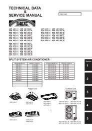
split system air conditioner
split system air conditioner
split system air conditioner

Create successful ePaper yourself
Turn your PDF publications into a flip-book with our unique Google optimized e-Paper software.
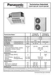
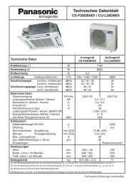
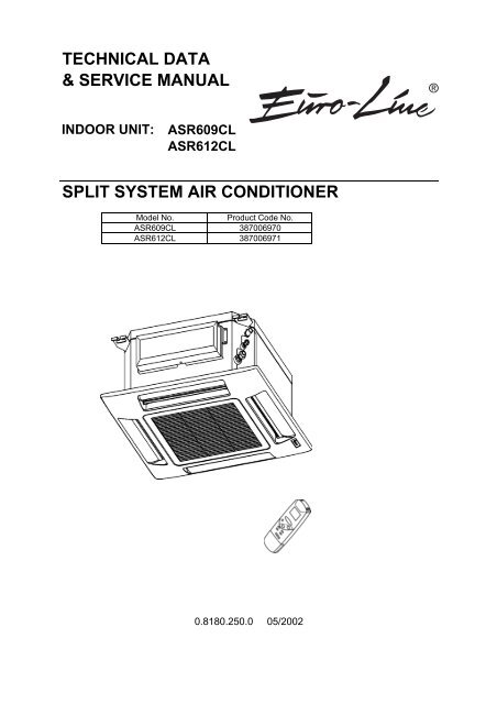
TECHNICAL DATA<br />
& SERVICE MANUAL<br />
INDOOR UNIT: ASR609CL<br />
ASR612CL<br />
SPLIT SYSTEM AIR CONDITIONER<br />
Model No. Product Code No.<br />
ASR609CL 387006970<br />
ASR612CL 387006971<br />
0.8180.250.0 05/2002<br />
®
IMPORTANT!<br />
Please read before installation<br />
This <strong>air</strong> conditioning <strong>system</strong> meets strict safety and operating<br />
standards.<br />
For the installer or service person, it is important to install or<br />
service the <strong>system</strong> so that it operates safely and efficiently.<br />
For safe installation and trouble-free operation, you must:<br />
• Carefully read this instruction booklet before beginning.<br />
• Follow each installation or rep<strong>air</strong> step exactly as shown.<br />
• Observe all local, state and national electrical codes.<br />
• Pay close attention to all warning and caution notices given in<br />
this manual.<br />
•The unit must be supplied with a dedicated electrical line.<br />
WARNING<br />
This symbol refers to a hazard or unsafe practice which can result<br />
in severe personal injury or death.<br />
CAUTION<br />
This symbol refers to a hazard or unsafe practice which can result<br />
in personal injury or product or property damage.<br />
If necessary, get help<br />
These instructions are all you need for most installation sites and<br />
maintenance conditions.<br />
If you require help for a special problem, contact our sale/service<br />
outlet or your certified dealer for additional instructions.<br />
In case of improper installation<br />
The manufacturer shall in no way be responsible for improper<br />
installation or maintenance service, including failure to follow the<br />
instructions in this document.<br />
SPECIAL PRECAUTIONS<br />
• During installation, connect before the refrigerant <strong>system</strong> and<br />
then the wiring one; proceed in the reverse orden when removing<br />
the units.<br />
WARNING When wiring<br />
ELECTRICAL SHOCK CAN CAUSE SEVERE<br />
PERSONAL INJURY OR DEATH. ONLY QUALIFIED,<br />
EXPERIENCED ELECTRICIANS SHOULD ATTEMPT<br />
TO WIRE THIS SYSTEM.<br />
• Do not supply power to the unit until all wiring and tubing are<br />
completed or reconnected and checked, to ensure the grounding.<br />
• Highly dangerous electrical voltages are used in this <strong>system</strong>.<br />
Carefully refer to the wiring diagram and these instructions when<br />
wiring.<br />
Improper connections and inadequate grounding can cause<br />
accidental injury and death.<br />
2<br />
• Ground the unit following local electrical codes.<br />
• The Yellow/Green wire cannot be used for any connection<br />
different from the ground connection.<br />
• Connect all wiring tightly. Loose wiring may cause overheating<br />
at connection points and a possible fire hazard.<br />
• Do not allow wiring to touch the refrigerant tubing, compressor,<br />
or any moving parts of the fan.<br />
• Do not use multi-core cable when wiring the power supply and<br />
control lines. Use separate cables for each type of line.<br />
When transporting<br />
Be careful when picking up and moving the indoor and outdoor<br />
units. Get a partner to help, and bend your knees when lifting to<br />
reduce strain on your back. Sharp edges or thin aluminium fins on<br />
the <strong>air</strong> <strong>conditioner</strong> can cut your fingers.<br />
When installing...<br />
… In a ceiling<br />
Make sure the ceiling is strong enough to hold the unit-weight.<br />
It may be necessary to build a strong wooden or metal frame to<br />
provide added support.<br />
… In a room<br />
Properly insulate any tubing run inside a room to prevent<br />
"sweating", which can cause dripping and water damage to<br />
walls and floors.<br />
... In moist or uneven locations<br />
Use a raised concrete base to provide a solid level foundation<br />
for the outdoor unit. This prevents damage and abnormal<br />
vibrations.<br />
... In area with strong winds<br />
Securely anchor the outdoor unit down with bolts and a metal<br />
frame. Provide a suitable <strong>air</strong> baffle.<br />
... In a snowy area (for heat pump-type <strong>system</strong>s)<br />
Install the outdoor unit on a raised platform that is higher then<br />
drifting snow. Provide snow vents.<br />
When connecting refrigerant tubing<br />
• Keep all tubing runs as short as possible.<br />
• Use the flare method for connecting tubing.<br />
• Apply refrigerant lubricant to the matching surfaces of the flare<br />
and union tubes before connecting them; screw by hand and<br />
then tighten the nut with a torque wrench for a leak-free<br />
connection.<br />
• Check carefully for leaks before starting the test run.<br />
NOTE:<br />
Depending on the <strong>system</strong> type, liquid and gas lines may be either<br />
narrow or wide. Therefore, to avoid confusion, the refrigerant<br />
tubing for your particular model is specified as narrow tube for<br />
liquid, wide tube for gas.<br />
When servicing<br />
• Turn the power OFF at the main power board before opening<br />
the unit to check or rep<strong>air</strong> electrical parts and wiring.<br />
• Keep your fingers and clothing away from any moving parts.<br />
• Clean up the site after the work, remembering to check that no<br />
metal scraps or bits of wiring have been left inside the unit being<br />
serviced.<br />
• Ventilate the room during the installation or testing the refrigeration<br />
<strong>system</strong>; make sure that, after the installation, no gas leaks are<br />
present, because this could produce toxic gas and dangerous<br />
if in contact with flames or heat-sources.
Table of Contents<br />
Page<br />
1. SPECIFICATIONS 4<br />
1-1 Unit specifications 4<br />
1-2 Major Component specifications 6<br />
1-3 Other Component specifications 8<br />
2. DIMENSIONAL DATA 9<br />
3. ELECTRICAL DATA 10<br />
3-1 Electric Wiring Diagrams 10<br />
4. FUNCTION 11<br />
4-1 Room Temperature Control 11<br />
4-2 Dry Operation (Dehumidification) 12<br />
4-3 Freeze Prevention (Cooling and Dry) 12<br />
4-4 Drain Pump and Float Switch 13<br />
5. TROUBLESHOOTING 14<br />
5-1 Check before and after troubleshooting 14<br />
5-2 Air <strong>conditioner</strong> does not operate 14<br />
5-3 Some part of <strong>air</strong> <strong>conditioner</strong> does not operate 18<br />
5-4 Air <strong>conditioner</strong> operates, but abnormalities are observed 20<br />
5-5 If a sensor is defective 21<br />
6. CHECKING ELECTRICAL COMPONENTS 22<br />
6-1 Measurement of Insulation Resistance 22<br />
6-2 Checking Continuity of Fuse on PCB Ass'y 23<br />
6-3 Checking Motor Capacitor 23<br />
7. MAINTENANCE 24<br />
7-1 Changing Address of Remote Control Unit in Indoor Unit 24<br />
3
1. SPECIFICATIONS<br />
1-1 Unit Specifications<br />
ASR609CL<br />
Power source<br />
Voltage rating<br />
Performance<br />
Capacity<br />
Air circulation (High/Med/Low) m³/h<br />
Features<br />
Controls/Temperature controls<br />
Control unit<br />
Timer<br />
Fan speed<br />
Airflow direction Vertical<br />
Air Filter<br />
Power noise level Hi/Me/Lo dB-A<br />
Refrigerant tubing connections<br />
Refrigerant Narrow tube mm(in.)<br />
tube diameter Wide tube mm(in.)<br />
Refrigerant<br />
Refrigerant tube kit / Air clean filter<br />
Dimensions & Weight<br />
Dimensions Unit Height mm<br />
Width mm<br />
Depth mm<br />
Ceiling panel Height mm<br />
Width mm<br />
Depth mm<br />
Package dimensions Unit Height mm<br />
Width mm<br />
Depth mm<br />
Volume m3<br />
Ceiling panel Height mm<br />
Width mm<br />
Depth mm<br />
Volume m3<br />
Weight Unit Net kg<br />
Shipping kg<br />
Ceiling panel Net kg<br />
Shipping kg<br />
4<br />
220 - 240V ~ 50Hz<br />
230V<br />
See catalogue with the requested matching<br />
500/450/400<br />
Microprocessor/ I.C. thermostat<br />
Wireless remote control unit<br />
ON/OFF 24 hours & Daily program, 1-hour OFF<br />
3 and Auto /1(Hi)<br />
Auto<br />
Washable, Anti-Mold<br />
45/42/38<br />
Flare type<br />
6,35 (1/4)<br />
9,52 (3/8)<br />
R407C<br />
Optional / ------<br />
273<br />
575<br />
575<br />
730<br />
730<br />
380<br />
744<br />
650<br />
0,18<br />
110<br />
800<br />
800<br />
0,07<br />
16,5<br />
21<br />
2,50<br />
4,70<br />
DATA SUBJECT TO CHANGE WITHOUT NOTICE<br />
64
ASR612CL<br />
Power source<br />
Voltage rating<br />
Performance<br />
Capacity<br />
Air circulation (High/Med/Low) m³/h<br />
Features<br />
Controls/Temperature controls<br />
Control unit<br />
Timer<br />
Fan speed<br />
Airflow direction Vertical<br />
Air Filter<br />
Power noise level Hi/Me/Lo dB-A<br />
Refrigerant tubing connections<br />
Refrigerant Narrow tube mm(in.)<br />
tube diameter Wide tube mm(in.)<br />
Refrigerant<br />
Refrigerant tube kit / Air clean filter<br />
Dimensions & Weight<br />
Dimensions Unit Height mm<br />
Width mm<br />
Depth mm<br />
Ceiling panel Height mm<br />
Width mm<br />
Depth mm<br />
Package dimensions Unit Height mm<br />
Width mm<br />
Depth mm<br />
Volume m3<br />
Ceiling panel Height mm<br />
Width mm<br />
Depth mm<br />
Volume m3<br />
Weight Unit Net kg<br />
Shipping kg<br />
Ceiling panel Net kg<br />
Shipping kg<br />
5<br />
220 - 240V ~ 50Hz<br />
230V<br />
See catalogue with the requested matching<br />
500/450/400<br />
Microprocessor/ I.C. thermostat<br />
Wireless remote control unit<br />
ON/OFF 24 hours & Daily program, 1-hour OFF<br />
3 and Auto /1(Hi)<br />
Auto<br />
Washable, Anti-Mold<br />
45/42/38<br />
Flare type<br />
6,35 (1/4)<br />
12,7 (1/2)<br />
R407C<br />
Optional / ------<br />
273<br />
575<br />
575<br />
64<br />
730<br />
730<br />
380<br />
744<br />
650<br />
0,18<br />
110<br />
800<br />
800<br />
0,07<br />
16,5<br />
21<br />
2,50<br />
4,70<br />
DATA SUBJECT TO CHANGE WITHOUT NOTICE
1-2 Major Component Specifications<br />
ASR609CL<br />
Controller PCB<br />
Part No.<br />
Controls<br />
Control circuit fuse<br />
Remote Control Unit<br />
Fan & Fan Motor<br />
Type<br />
Centrifugal fan<br />
Q'ty ……. Dia. and lenght mm<br />
1…. Ø 280 / L 175<br />
Fan motor model…Q'ty<br />
R4E280-AK43-13 …1<br />
No. Of poles…rpm (230 V)<br />
4… 620/560/490/240<br />
Running Amps A<br />
0,18<br />
Power input W<br />
41<br />
Coil resistance (Ambient temp. 20 °C ) Ω BLU-BLK: 463,5<br />
BLK-GRY: 33,5<br />
GRY-RED: 38,5<br />
RED-WHT: 143,5<br />
Safety devices Type<br />
Operating temp. Open °C<br />
Close °C<br />
Run capacitor µF<br />
VAC<br />
Flap Motor<br />
Type<br />
Model<br />
Rating<br />
No of poles …rpm<br />
Nominal output W<br />
Coil resistance (Ambient temp. 20 °C ) kΩ<br />
Heat Exch. Coil<br />
Coil<br />
Rows<br />
Fin pitch mm<br />
face area m2<br />
6<br />
XR99/129E<br />
Microprocessor<br />
250 V - 3,15 A<br />
RCS-6PN4E-G<br />
WHT-BLU: 80,0<br />
Internal thermal protector<br />
160 ± 10K<br />
130 ± 15K<br />
1,5<br />
450<br />
Synchro motor<br />
M2LJ24ZE31<br />
AC 208/230V 50/60Hz<br />
8 …. 2,5/3,0<br />
3/2,5<br />
16,45 ± 15%<br />
Aluminium plate fin / Copper tube<br />
1<br />
1,3<br />
0,258<br />
DATA SUBJECT TO CHANGE WITHOUT NOTICE
ASR612CL<br />
Controller PCB<br />
Part No.<br />
Controls<br />
Control circuit fuse<br />
Remote Control Unit<br />
Fan & Fan Motor<br />
Type<br />
Centrifugal fan<br />
Q'ty ……. Dia. and lenght mm<br />
1…. Ø 280 / L 175<br />
Fan motor model…Q'ty<br />
R4E280-AK43-13 …1<br />
No. Of poles…rpm (230 V, Cool-Heat)<br />
4… 620/560/490/240<br />
Running Amps A<br />
0,18<br />
Power input W<br />
41<br />
Coil resistance (Ambient temp. 20 °C ) Ω BLU-BLK: 463,5<br />
BLK-GRY: 33,5<br />
GRY-RED: 38,5<br />
RED-WHT: 143,5<br />
Safety devices Type<br />
Operating temp. Open °C<br />
Close °C<br />
Run capacitor µF<br />
VAC<br />
Flap Motor<br />
Type<br />
Model<br />
Rating<br />
No of poles …rpm<br />
Nominal output W<br />
Coil resistance (Ambient temp. 20 °C ) kΩ<br />
Heat Exch. Coil<br />
Coil<br />
Rows<br />
Fin pitch mm<br />
face area m2<br />
7<br />
XR99/129E<br />
Microprocessor<br />
250 V - 3,15 A<br />
RCS-6PN4E-G<br />
WHT-BLU: 80,0<br />
Internal thermal protector<br />
160 ± 10K<br />
130 ± 15K<br />
1,5<br />
450<br />
Synchro motor<br />
M2LJ24ZE31<br />
AC 208/230V 50/60Hz<br />
8 …. 2,5/3,0<br />
3/2,5<br />
16,45 ± 15%<br />
Aluminium plate fin / Copper tube<br />
1<br />
1,3<br />
0,258<br />
DATA SUBJECT TO CHANGE WITHOUT NOTICE
1-3 Other Component Specifications ASR609CL<br />
ASR612CL<br />
Trasformer<br />
Rating Primary<br />
Secondary<br />
Capacity<br />
Coil resistance Ω (at 21°C)<br />
Thermal cut-off temp.<br />
Thermistor ( Coil sensor TH1)<br />
Resistance ΚΩ<br />
Thermistor ( Room sensor TH2)<br />
Resistance ΚΩ<br />
Drain pump<br />
Model<br />
Rating Voltage<br />
Input<br />
Total head capacity<br />
Safety float switch<br />
Model<br />
Contact rating<br />
8<br />
ATR-J105<br />
AC 230V, 50/60Hz<br />
19V - 0.526A<br />
10 VA<br />
Primary (WHT-WHT): 205 ± 10%<br />
Secondary (BRN-BRN): 2,0 ± 10%<br />
150°C<br />
PBC-41E-S14<br />
0 °C 15,3 ± 5%<br />
DTN-TKS134B<br />
25 °C 5,0 ± 3%<br />
PC 309564003<br />
220/240V - 50Hz<br />
14W<br />
0,4 l/min<br />
BI 1300 2725<br />
230V AC/DC - 0,5A
2. DIMENSIONAL DATA<br />
9
3. ELECTRICAL DATA<br />
3-1 Electric Wiring Diagrams<br />
10
4. FUNCTION<br />
4-1. Room Temperature Control<br />
■ Cooling<br />
● Room temperature control is obtained by cycling the compressor ON and OFF under control of the room<br />
temperature sensor in the remote control unit.<br />
● The room temperature (and other information) is transmitted every 5 minutes by the remote control unit to the<br />
controller in the indoor unit.<br />
set temp.<br />
T+1 °C<br />
T °C<br />
Compressor<br />
Outdoor fan<br />
More than<br />
5 minutes<br />
Thermo.<br />
OFF<br />
Signal from remote control unit<br />
5 minutes 5 minutes 5 minutes 5 minutes 5 minutes 5 minutes 5 minutes<br />
Thermo.<br />
ON<br />
5 minutes<br />
Thermo.<br />
OFF<br />
3 minutes<br />
ON OFF ON OFF ON OFF<br />
ON OFF ON OFF ON OFF<br />
Indoor fan Set speed<br />
Thermo.<br />
ON<br />
Thermo.<br />
ON<br />
3 seconds 3 seconds<br />
Thermo.<br />
ON<br />
Room temp.<br />
Thermo.<br />
OFF<br />
● The control circuit will not attempt to turn the compressor ON until the compressor has been OFF for at least<br />
3 minutes. To protect the compressor from stalling out when trying to start against the high side refrigerant<br />
pressure, the control circuit has a built-in automatic time delay to allow the internal pressure to equalize.<br />
● As a protective measure, the control circuit switches the compressor OFF not before than 5 minutes<br />
of compressor operation.<br />
● Thermo. ON : When the room temperature is above T + 1°C (T°C is set temperature).<br />
Compressor ➞ ON<br />
● Thermo. OFF : When the room temperature is equal to or below set temperature T°C.<br />
Compressor ➞ OFF<br />
11
4-2. Dry Operation (Dehumidification)<br />
● Dry operation uses the ability of the cooling cycle to remove moisture from the <strong>air</strong>, but by running at low level to<br />
dehumidify without greatly reducing the room temperature. The <strong>air</strong> <strong>conditioner</strong> repeats the ON/OFF cycle<br />
automatically as shown in the chart below according to the room temperature.<br />
NOTE<br />
T+2 °C<br />
Set temp. T °C<br />
T–1 °C<br />
Room temp. 15 °C<br />
Room temp.<br />
Cooling operation<br />
*Dry A zone<br />
Compressor : Continuous operation<br />
FMI (indoor fan) : L (low speed) / LL (very low speed) intermittent ventilation<br />
only while the compressor is ON.<br />
*Dry B zone<br />
Compressor : Intermittent operation (ON for 3 minutes and OFF for 9 minutes)<br />
FMI (indoor fan) : L (low speed) / LL (very low speed) intermittent ventilation<br />
only while the compressor is ON.<br />
Monitor zone<br />
Both the indoor and outdoor units stop.<br />
● Intermittent ventilation occurs by switching the indoor fan speed between L ↔ LL.<br />
● Dry operation does not occur when the room temperature is under 15°C, which is the monitor zone.<br />
● When the compressor stops, the indoor fan stops as well.<br />
4-3. Freeze Prevention (Cooling and Dry)<br />
● This function prevents freezing of the indoor heat exchange coil.<br />
● When the compressor has been running for 6 minutes or more and the temperature of the indoor heat<br />
exchange coil falls below –1°C, the control circuit stops the compressor for at least 6 minutes. The compressor<br />
does not start again until the temperature rises above 8°C or 6 minutes has elapsed.<br />
T+1 °C<br />
Set temp. T °C<br />
Indoor heat exch.<br />
coil temp.<br />
–1 °C<br />
Compressor<br />
Indoor fan<br />
Room temp.<br />
More than<br />
6 minutes<br />
ON OFF ON ON OFF ON<br />
Set speed<br />
6 minutes<br />
12<br />
More than<br />
6 minutes<br />
Thermo. OFF<br />
More than<br />
6 minutes<br />
Set speed<br />
Thermo. ON
4-4 Drain Pump and Float Switch<br />
Compressor<br />
Drain Pump ON OFF ON OFF ON ON<br />
Float Switch<br />
ON OFF ON OFF<br />
OFF ON OFF ON<br />
OFF<br />
NOTE:<br />
Either in Heating or another mode or the unit is stopped, when the float switch is turned ON,<br />
the drain pump operates for 20 minutes minimum<br />
13<br />
3'min<br />
20'min. 20'min.<br />
ON
5. 6. TROUBLESHOOTING<br />
5-1. 6-1. Check before and after troubleshooting<br />
WARNING<br />
Hazardous voltage can cause ELECTRIC SHOCK or<br />
DEATH. Disconnect power or turn off circuit breaker<br />
before you start checking or servicing.<br />
5-1-1. 6-1-1. Check power supply wiring.<br />
● Check that power supply wires are correctly connected to terminals L and N on the terminal plate in the indoor<br />
unit.<br />
5-1-2. 6-1-2. Check inter-unit wiring.<br />
● Check that inter-unit wiring is correctly connected to the outdoor unit from the indoor unit.<br />
5-1-3. 6-1-3. Check power supply.<br />
● Check that voltage is in specified range (±10% of the rating).<br />
● Check that power is being supplied.<br />
5-1-4. 6-1-4. Check lead wires and connectors in indoor and outdoor units.<br />
● Check that coating of lead wires is not damaged.<br />
● Check that lead wires and connectors are firmly connected.<br />
● Check that wiring is correct.<br />
5-2. Air <strong>conditioner</strong> does not operate.<br />
5-2-1. Circuit breaker trips (or fuse blows).<br />
A. When the circuit breaker is set to ON, it trips immediately. (Resetting is not possible.)<br />
● There is a possibility of ground fault.<br />
● Check insulation resistance.<br />
If resistance value is 2MΩ or less, insulation is defective (“NO”).<br />
WARNING<br />
* Set circuit breaker to OFF.<br />
1 Remove inter-unit wires from<br />
terminal plate in outdoor unit.<br />
• Measure insulation resistance<br />
of outdoor unit.<br />
2 Remove inter-unit wires from<br />
terminal plate in indoor unit.<br />
Then, pull the power plug out of<br />
the wall outlet<br />
• Measure insulation resistance<br />
of indoor unit.<br />
NO<br />
NO<br />
14<br />
Insulation of<br />
outdoor unit<br />
is defective.<br />
• Measure insulation<br />
resistance of electrical<br />
parts in outdoor unit.<br />
Insulation of<br />
indoor unit<br />
is defective.<br />
• Measure insulation<br />
resistance of electrical<br />
parts in indoor unit.
B. Circuit breaker trips in several minutes after turning the <strong>air</strong> <strong>conditioner</strong> on.<br />
● There is a possibility of short circuit.<br />
• Check capacity of circuit breaker.<br />
Capacity of circuit breaker is<br />
suitable.<br />
• Measure resistance of outdoor fan<br />
motor winding.<br />
• Measure resistance of compressor<br />
motor winding.<br />
5-2-2. 6-2-2. Neither indoor nor outdoor unit runs.<br />
A. Power is not supplied.<br />
• Check power supply.<br />
Power is being supplied to the<br />
indoor unit.<br />
B. Check "OPERATION selector" switch in the indoor unit.<br />
• OPERATION selector switch is set<br />
in ON position.<br />
NO<br />
Set OPERATION selector switch<br />
to ON.<br />
NO<br />
NO<br />
YES<br />
15<br />
Replace with suitable<br />
one (larger capacity).<br />
Circuit breaker<br />
is tripped.<br />
Power failure<br />
Reset breaker.<br />
Wait for recovery<br />
or contact power<br />
company.<br />
Indoor PCB Ass'y is defective.
C. Check remote control unit.<br />
• Try to run with another remote<br />
control unit.<br />
OK<br />
First remote control unit is defective.<br />
• Check for residue buildup on<br />
transmitter of remote control unit.<br />
• Check for residue buildup on remote<br />
control receiver on front of indoor<br />
unit.<br />
D. Check fuse on the indoor PCB Ass'y.<br />
• Check fuse on indoor PCB Ass'y<br />
for continuity. (F)<br />
OK<br />
• Check operation lamp to see<br />
if light is ON.<br />
Light is OFF<br />
• Measure resistance of primary and<br />
secondary winding of transformer.<br />
(TR)<br />
OK<br />
• Indoor PCB Ass'y is defective.<br />
E. Check TIMER on the remote control unit.<br />
• Timer is turned ON. Check to see<br />
if ON or is displayed on<br />
remote control<br />
If fuse has been blown,<br />
YES<br />
16<br />
• Measure resistance of indoor and<br />
outdoor fan motor winding.<br />
(FM)<br />
OK<br />
• Measure resistance of compressor<br />
motor winding. (CM)<br />
• Replace the fuse.<br />
Clean transmitter.<br />
Clean receiver.<br />
OK<br />
Cancel the timer mode.
5-2-3. 6-2-3. Only outdoor unit does not run.<br />
A. Check setting temperature.<br />
COOL<br />
Is room temperature too low ?<br />
NO<br />
Try to lower setting temperature by<br />
temperature setting button ( button).<br />
OK<br />
5-2-4. 6-2-4. Only Indoor unit does not run.<br />
• Indoor PCB Ass'y is defective.<br />
Outdoor unit still does<br />
not run.<br />
• Try to run using another remote<br />
control unit.<br />
Remote control unit is defective.<br />
17
5-3. Some part of <strong>air</strong> <strong>conditioner</strong> does not operate.<br />
5-3-1. Only indoor fan does not run.<br />
• Check fan rotation.<br />
Turn fan gently once or twice by<br />
hand.<br />
• Measure resistance of indoor fan<br />
motor winding.<br />
OK<br />
5-3-2. Only flap motor does not run.<br />
• Measure resistance of flap motor<br />
winding.<br />
5-3-3. Only outdoor fan does not run.<br />
• Check fan rotation.<br />
Turn fan gently once or twice by<br />
hand.<br />
• Measure resistance of outdoor fan<br />
motor winding.<br />
OK<br />
• Check fan motor capacitor.<br />
Fan cannot<br />
be turned.<br />
Fan cannot<br />
be turned.<br />
• Check fan casing<br />
foreign matter on<br />
inside.<br />
Fan motor burnout<br />
or foreign matter in<br />
bearings.<br />
OK<br />
• Check fan motor capacitor. PCB assy is defective.<br />
18<br />
• Check fan casing<br />
foreign matter on<br />
inside.<br />
Fan motor burnout<br />
or foreign matter in<br />
bearings.<br />
Remove foreign<br />
matter or rep<strong>air</strong>.<br />
Rep<strong>air</strong> or replace.<br />
Remove foreign<br />
matter or rep<strong>air</strong>.<br />
Rep<strong>air</strong> or replace.
5-3-4. Only compressor does not run<br />
Check compressor motor Overload relay is working<br />
capacitor C1 (either OLR T or OLR A)<br />
Measure resistance of Temperature of compressor<br />
compressor motor winding is abnormally high<br />
Measure power supply voltage<br />
The voltage is too low<br />
NO<br />
Rotor may be locked up<br />
5-3-5. Compressor and outdoor fan do not run<br />
Float switch turned ON<br />
Check if drain pump<br />
runs normaly<br />
NO Replace the drain pump<br />
Verify if drain condensate tube<br />
is obstructed<br />
Remove obstruction<br />
YES<br />
YES<br />
YES<br />
YES<br />
YES<br />
YES<br />
Refrigerant gas shortage Charge refrigerant gas<br />
19<br />
NO
5-4.<br />
6-4. Air <strong>conditioner</strong> operates, but abnormalities are observed.<br />
6-4-1. 5-4-1. Poor cooling.<br />
• Check position of remote control unit.<br />
• Cool <strong>air</strong> from <strong>air</strong> <strong>conditioner</strong><br />
reaches position directly.<br />
• Wide and narrow tubes between<br />
indoor unit and outdoor unit are<br />
insulated.<br />
YES<br />
• Measure temperature of suction and<br />
discharge <strong>air</strong> of <strong>air</strong> <strong>conditioner</strong>.<br />
Check for clogging of <strong>air</strong> filter.<br />
• Fan speed is set to LOW.<br />
• Review cooling load estimate,<br />
if performance of <strong>air</strong> <strong>conditioner</strong> is<br />
normal.<br />
6-4-2. 5-4-2. Excessive cooling.<br />
• Set temperature is suitable.<br />
• Remote control unit is placed where<br />
it can detect room temperature<br />
properly.<br />
YES<br />
NO<br />
Temperature<br />
difference<br />
is small.<br />
Temperature difference between<br />
suction and discharge <strong>air</strong> is<br />
large enough (approx. 10 deg. or more).<br />
Air filter is clogged.<br />
YES<br />
NO<br />
NO<br />
20<br />
Possibility of<br />
gas shortage.<br />
Change position of remote<br />
control unit.<br />
Insulate both wide and narrow<br />
tubes separately and then<br />
tape together.<br />
Charge refrigerant<br />
gas.<br />
Clean filter.<br />
Set fan speed to either<br />
HIGH or MEDIUM.<br />
Reduce cooling<br />
load or replace the <strong>air</strong><br />
<strong>conditioner</strong> with larger<br />
capacity.<br />
Set temperature to higher<br />
value using temperature<br />
setting buttons of the remote<br />
control unit.<br />
Change position of remote<br />
control unit.
5-5. If a sensor is defective.<br />
5-5-1. Thermistor (TH1 or TH2) is defective.<br />
• Operation lamp on front side of<br />
indoor unit is blinking. (*)<br />
YES<br />
• Indoor coil thermistor (TH1 ) or room<br />
<strong>air</strong> thermistor (TH2 ) is defective.<br />
• Replace the thermistor.<br />
NOTE Alarm Signal (*)<br />
Operation lamp on the front side of the indoor unit will blink when either indoor coil thermistor or room<br />
<strong>air</strong> thermistor is defective. At the same time the outdoor unit will stop. Indoor unit will operate only for ventilation.<br />
21<br />
YES
6. CHECKING ELECTRICAL COMPONENTS<br />
6-1. Measurement of Insulation<br />
Resistance<br />
● The insulation is in good condition if the resistance<br />
exceeds 2MΩ.<br />
6-1-1. Power Supply Wires<br />
Clamp the grounding terminal of the power plug with a<br />
lead clip of the insulation resistance tester and<br />
measure the resistance by placing a probe on both<br />
the two power terminals. (Fig. 1)<br />
Then, also measure the resistance between the<br />
grounding and other power terminals. (Fig. 1)<br />
6-1-2. Indoor Unit<br />
Clamp a metallic part of the unit with the lead clip of<br />
the insulation resistance tester and measure the<br />
resistance by placing a probe on each terminal screw<br />
where power supply lines are connected on the<br />
terminal plate. (Fig. 2)<br />
6-1-3. Outdoor Unit<br />
Clamp an aluminum plate fin or copper tube with the<br />
lead clip of the insulation resistance tester and<br />
measure the resistance by placing a probe on each<br />
terminal screw on the terminal plate. (Fig. 2)<br />
Note that the ground line terminal should be skipped<br />
for the check.<br />
6-1-4. Measurement of Insulation<br />
Resistance for Electrical Parts<br />
Disconnect the lead wires of the desired electric part<br />
from terminal plate, capacitor, etc. Similarly disconnect<br />
the connector. Then measure the insulation resistance.<br />
(Figs. 3 and 4)<br />
NOTE<br />
Refer to Electric Wiring Diagram.<br />
If the probe cannot enter the poles because the hole is<br />
too narrow then use a probe with a thinner pin.<br />
22<br />
NOTE<br />
Copper<br />
tube or<br />
metallic part<br />
power plug<br />
(Local supply)<br />
probe<br />
Clip<br />
Clip<br />
Copper<br />
tube or<br />
metallic part<br />
Ground<br />
Terminal plate<br />
Insulation<br />
tester<br />
Insulation<br />
tester<br />
The shape of the power plug may differ from that<br />
of the <strong>air</strong> <strong>conditioner</strong> which you are servicing.<br />
Metallic<br />
part<br />
Clip<br />
Probe<br />
From fan motor,<br />
compressor and<br />
other parts<br />
Insulation<br />
tester<br />
Insulation<br />
tester<br />
Probe<br />
Probe<br />
Fig. 1<br />
Fig. 2<br />
Fig. 3<br />
Fig. 4
6-2. 7-2. Checking Continuity of Fuse<br />
on PCB Ass'y<br />
● Remove the PCB Ass’y from the electrical<br />
component box. Then pull out the fuse from the PCB<br />
Ass’y. (Fig. 5)<br />
● Check for continuity using a multimeter as shown in<br />
Fig. 6.<br />
6-3. 7-3. Checking Motor Capacitor<br />
Remove the lead wires from the capacitor terminals,<br />
and then place a probe on the capacitor terminals as<br />
shown in Fig. 7. Observe the deflection of the pointer,<br />
setting the resistance measuring range of the<br />
multimeter to the maximum value.<br />
The capacitor is “good” if the pointer bounces to a<br />
great extent and then gradually returns to its original<br />
position.<br />
The range of deflection and deflection time differ<br />
according to the capacity of the capacitor.<br />
23<br />
Compressor motor<br />
capacitor<br />
Fuse<br />
PCB Ass’y<br />
Fan motor<br />
capacitor<br />
Fuse<br />
Multimeter<br />
Fig. 5<br />
Fig. 6<br />
Fig. 7
7. MAINTENANCE<br />
7-1 Changing Address of Remote Control Unit in Indoor Unit<br />
If you are installing more than 1 indoor unit (up to 2) in the same room, it is necessary for you to assign each unit<br />
its own address, so each can be operated by its own separate remote control unit. You assign the addresses by<br />
matching the remocon address on the PCB of each indoor unit with the switch positions of its remote control unit.<br />
To change address on PCB<br />
(1) Set the switch n.2 to "off" position on the address dip switch (S01)<br />
(see detail on figure)<br />
To change address on Remote Control Unit<br />
NB.: Once changed, you cannot restore the original address<br />
(1) Remove the batteries before changing the address<br />
(2) Remove tab marked A to change the address of the remote control unit<br />
(when is removed, the address is automatically set to B)<br />
(3) After inserting the batteries, press ACL button<br />
24
Via Varese, 90 - 21013 Gallarate - Va - Italy<br />
Tel. +39 0331 755111 - Fax +39 0331 776240<br />
www.argoclima.it