APG100 Active Pirani Gauge Graphic - Ultimate Vacuum
APG100 Active Pirani Gauge Graphic - Ultimate Vacuum
APG100 Active Pirani Gauge Graphic - Ultimate Vacuum

You also want an ePaper? Increase the reach of your titles
YUMPU automatically turns print PDFs into web optimized ePapers that Google loves.
<strong>APG100</strong> <strong>Active</strong> <strong>Pirani</strong> <strong>Gauge</strong><br />
Description Item Number<br />
<strong>APG100</strong> - XM NW16 D026-01-000<br />
<strong>APG100</strong> - XM NW25 D026-02-000<br />
<strong>APG100</strong> - XLC NW16 D026-03-000<br />
<strong>APG100</strong> - XLC NW25 D026-04-000<br />
Introduction<br />
<strong>Graphic</strong><br />
Instruction Manual<br />
D026-01-880 Iss A Sep 06<br />
Scope and definitions<br />
This manual provides installation, operation and maintenance<br />
instructions for the BOC Edwards <strong>APG100</strong> <strong>Active</strong> <strong>Pirani</strong> <strong>Gauge</strong>. You<br />
must use the <strong>APG100</strong> as specified in this manual.<br />
Read this manual before you install and operate the <strong>APG100</strong>.<br />
Important safety information is highlighted as WARNING and<br />
CAUTION instructions; you must obey these instructions. The use of<br />
WARNINGS and CAUTIONS is defined below.<br />
WARNING<br />
Warnings are given where failure to observe<br />
the instruction could result in injury or death<br />
to people.<br />
CAUTION<br />
Cautions are given where failure to observe the instruction could<br />
result in damage to the equipment, associated equipment and<br />
process.<br />
The following symbols appear on the <strong>APG100</strong>:<br />
Warning - refer to accompanying documents.<br />
BOC Edwards offer European customers a recycling<br />
service.<br />
1<br />
Description<br />
The <strong>APG100</strong> is a <strong>Pirani</strong> gauge which measures vacuum pressures in the<br />
range 10 -4 mbar to 1000 mbar. It operates using the principle of<br />
thermal conductivity in which the rate of heat loss from a heated<br />
filament is dependent on the pressure of gas surrounding the filament.<br />
The <strong>APG100</strong> is available in two versions: the 'M' version can measure<br />
pressure down to 10 -3 mbar and is suitable for general applications;<br />
the 'LC' version can measure pressure down to 10 -4 mbar and is also<br />
suitable for use in corrosive applications.<br />
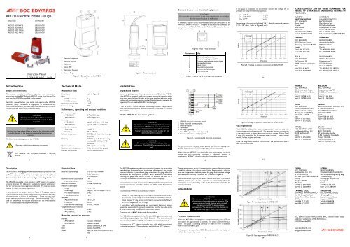
A general view of the gauge is shown in Figure 1. The gauge features<br />
a detachable tube which allows a replacement to be fitted in the event<br />
of contamination or failure of the filament. There are two pushbutton<br />
switches on the top of the gauge. The switch labelled "CAL" is<br />
used for atmosphere and vacuum calibration and the switch labelled<br />
"S/P" is used to adjust the set-point threshold.<br />
2<br />
1. Electrical connector<br />
2. Set-point button<br />
3. Cal button<br />
4. Status LED<br />
5. Electronics housing<br />
6. <strong>Vacuum</strong> flange<br />
Figure 1 - General view of the <strong>APG100</strong><br />
3<br />
Technical Data<br />
Mechanical data<br />
Dimensions<br />
Mass:<br />
Refer to Figure 2<br />
NW16 versions 85 g<br />
NW25 versions 100 g<br />
Internal volume of tube 5 cm 3<br />
Enclosure rating IP40<br />
Performance, operating and storage conditions<br />
Measurement range<br />
<strong>APG100</strong>-XM 10 -3 to 1000 mbar<br />
<strong>APG100</strong>-XLC 10 -4 Accuracy<br />
to 1000 mbar<br />
<strong>APG100</strong>-XM typically ± 15 % at < 100 mbar<br />
<strong>APG100</strong>-XLC<br />
Ambient temperature<br />
typically ± 15 % at < 10 mbar<br />
Operating 5 to 60 °C<br />
Storage -30 to +70 °C<br />
Bakeout temperature 150 °C (with electronics housing<br />
removed)<br />
Humidity 80 % RH up to 31 °C decreasing<br />
linearly to 50 % RH at 40 °C<br />
and above<br />
Maximum altitude 3000 m (indoor use only)<br />
Maximum internal pressure 10 bar absolute (9 bar gauge)<br />
Filament temperature 100 °C above ambient<br />
Electrical data<br />
Electrical supply voltage 15 to 30 V d.c. nominal<br />
13.5 V minimum<br />
32 V maximum<br />
Maximum power consumption 1 W<br />
Max inrush current 150 mA<br />
Electrical connector<br />
Pressure output signal<br />
FCC68 / RJ45 8-way<br />
Range 1.9 to 9.1 V<br />
Error range output < 1.8 V or output > 9.2 V<br />
Min load impedance 10 kΩ<br />
Max output current<br />
Set-point<br />
1 mA<br />
Adjustment range 1.8 to 9.2 V<br />
Hysteresis 500 mV<br />
Max external load rating<br />
<strong>Gauge</strong> identification resistance<br />
30 V d.c., 100 mA<br />
<strong>APG100</strong>-XM 36 kΩ<br />
<strong>APG100</strong>-XLC 43 kΩ<br />
Materials exposed to vacuum<br />
4<br />
Filament<br />
<strong>APG100</strong>-XM Tungsten / Rhenium<br />
<strong>APG100</strong>-XLC Platinum / Iridium<br />
Tube Stainless Steel 316L & 304L<br />
Filter Stainless Steel 316L<br />
Other Glass, Ni, NiFe, PTFE (<strong>APG100</strong>-XLC<br />
only)<br />
5<br />
Installation<br />
Unpack and inspect<br />
Figure 2 - Dimensions (mm)<br />
Remove all packing materials and protective covers. Check the <strong>APG100</strong>.<br />
If the <strong>APG100</strong> is damaged, notify your supplier and carrier in writing within<br />
three days: state the Item Number of the gauge together with your order<br />
number and your suppliers invoice number. Retain all packing materials for<br />
inspection. Do not use the <strong>APG100</strong> if it is damaged.<br />
If the <strong>APG100</strong> is not to be used immediately, replace the protective<br />
covers. Store the <strong>APG100</strong> in suitable conditions as described in Technical<br />
Data section.<br />
Fit the <strong>APG100</strong> to a vacuum system<br />
WARNING<br />
You must use a Co-seal or trapped ‘O’ ring carrier<br />
to connect an <strong>APG100</strong> to a vacuum system if the<br />
pressure is likely to exceed atmospheric pressure.<br />
Standard centring rings are not suitable for use<br />
above atmospheric pressure.<br />
WARNING<br />
Do not use the <strong>APG100</strong> for safety critical<br />
applications. The <strong>APG100</strong> is not intended to be failsafe.<br />
The <strong>APG100</strong> can be mounted in any orientation however the gauge tubes<br />
are individually factory calibrated in nitrogen whilst vertical. For correct<br />
pressure indication in your chosen gauge orientation, the gauge should be<br />
recalibrated at atmospheric pressure. BOC Edwards recommends<br />
mounting the gauge tube vertical in order to minimise the build up of<br />
process particulates and condensable vapours within the gauge.<br />
For optimum accuracy it is recommended that both the atmosphere and<br />
vacuum adjustment is carried out before use. Refer to the Maintenance<br />
section.<br />
To connect the <strong>APG100</strong> to your vacuum system:<br />
6<br />
Use an 'O' ring / centring-ring or Co-Seal to connect an <strong>APG100</strong> with<br />
an NW16 or NW25 flange to a similar flange on the vacuum system.<br />
Use a stepped 'O' ring carrier or Co-Seal to connect an <strong>APG100</strong> with<br />
an NW16 flange to an NW10 flange.<br />
In accordance with good practice, we recommend that your vacuum<br />
system has a secure Earth (ground) connection, and that the tube of the<br />
<strong>APG100</strong> is electrically connected to the vacuum system.<br />
Connect to a BOC Edwards Controller<br />
The <strong>APG100</strong> is compatible with the TIC and ADC digital controllers and<br />
the AGD analogue display from BOC Edwards. The controllers will<br />
automatically recognise the gauge and display the measured pressure.<br />
To connect to a BOC Edwards controller use a cable which is terminated<br />
in suitable connectors. These cables are available from BOC Edwards.<br />
7<br />
8<br />
Connect to your own electrical equipment<br />
CAUTION<br />
Do not make any connection to the gauge identification pin (pin 4) as<br />
this may cause the gauge to malfunction.<br />
A schematic diagram of the recommended electrical connections to the<br />
<strong>APG100</strong> is shown in Figure 4. The pins on the electrical connector are<br />
used as shown in Table 1. Refer to the Technical Data section for more<br />
detailed specifications.<br />
Pin number Use<br />
1<br />
2<br />
3<br />
4<br />
5<br />
6<br />
7<br />
8<br />
Figure 3 - RJ45 8-way connector<br />
Electrical supply positive<br />
Electrical supply ground (0 V)<br />
Pressure measurement output signal<br />
<strong>Gauge</strong> identification<br />
Signal ground<br />
Set-point output signal<br />
Remote calibration input<br />
Not connected<br />
Table 1 - Pins on the <strong>APG100</strong> electrical connector<br />
9<br />
1. <strong>APG100</strong> electrical connector socket<br />
2. Cable electrical connector plug<br />
3. Electrical supply<br />
4. Voltmeter<br />
5. d.c. relay (optional)<br />
6. Back EMF suppression diode (optional)<br />
7. Remote calibration switch (optional)<br />
Figure 4 - Recommended electrical connections<br />
Do not connect the electrical supply ground (pin 2) to the signal ground<br />
(pin 5). If you do, the <strong>APG100</strong> output signal will be inaccurate.<br />
When using the <strong>APG100</strong> in an electrically noisy environment you should<br />
ensure that your measuring equipment is adequately immune to<br />
interference. All BOC Edwards controllers have adequate immunity.<br />
The set-point output on pin 6 is an active low open-collector transistor<br />
suitable for driving a d.c. relay or control logic. If you connect a relay you<br />
must use a suppression diode, to protect the gauge from transient voltages<br />
generated when the relay is switched off, as shown in Figure 4.<br />
Make a connection to pin 7 if you require remote calibration. Momentarily<br />
(>50ms) connect pin 7 to pin 2 (ground) to automatically adjust the<br />
atmosphere or vacuum reading. Refer to the Maintenance section for the<br />
correct procedure.<br />
Operation<br />
WARNING<br />
Do not use the <strong>APG100</strong> to measure the pressure<br />
of explosive or flammable gasses or mixtures. The<br />
gauge contains a heated filament which normally<br />
operates around 100°C above ambient<br />
temperature. The temperature of the filament can<br />
be substantially higher under fault conditions.<br />
Pressure measurement<br />
When the <strong>APG100</strong> is connected to a power supply the status LED will<br />
turn amber for approximately 2 seconds. The status LED will then turn<br />
green if the gauge is operating correctly or red if an error is detected.<br />
Refer to the fault finding guide.<br />
If the gauge is connected to a BOC Edwards controller the display will<br />
indicate the measured pressure.<br />
10<br />
11<br />
If the gauge is connected to a voltmeter convert the voltage (V) to<br />
pressure (P) using the following equations:<br />
P = 10 (V - 6) P in mbar<br />
P = 10 (V - 6.125) P in Torr<br />
P = 10 (V-4) P in Pa<br />
For example if the measured voltage V = 4 V , then the measured pressure<br />
P = 1 x 10 -2 mbar. Refer to Figures 5 and 6.<br />
Figure 5 - Voltage to pressure conversion for <strong>APG100</strong>-XM<br />
Figure 6 - Voltage to pressure conversion for <strong>APG100</strong>-XLC<br />
Gas dependency<br />
12<br />
The <strong>APG100</strong> is calibrated for use in nitrogen, and will read correctly with<br />
dry air, oxygen and carbon monoxide. For any other gas type a conversion<br />
is required in order to obtain the correct pressure reading. Figures 7 and<br />
8 show the conversion for 6 common gases: nitrogen, argon, carbon<br />
dioxide, helium, krypton and neon.<br />
If you are using a BOC Edwards TIC controller, the gas calibration data is<br />
built into the controller.<br />
13<br />
Figure 7 - Gas dependency of <strong>APG100</strong>-XM<br />
Figure 8 - Gas dependency of <strong>APG100</strong>-XLC<br />
14<br />
PLEASE CONTACT ANY OF THESE COMPANIES FOR<br />
DETAILS OF OTHER SALES AND SERVICE CENTRES IN<br />
YOUR AREA.<br />
EUROPE/ AMERICAS<br />
UNITED KINGDOM USA HEADQUARTERS<br />
BOC EDWARDS BOC EDWARDS<br />
Manor Royal One Edwards Park<br />
Crawley 301 Ballardvale Street<br />
West Sussex Wilmington, MA 01887<br />
RH10 9LW Tel +1 978 658 5410<br />
Tel +44 (0)1293 528844 Fax +1 978 658 7969<br />
Fax +44 (0)1293 533453 Toll free (USA only)1 800 848 9800<br />
CANADA GERMANY<br />
BOC EDWARDS BOC EDWARDS<br />
5975 Falbourne Street Ammerthalstraße 36<br />
Mississauga, Ontario L5R3W6 85551 Kirchheim<br />
Canada Munich<br />
Tel +1 800 387 4076 Tel +49 89 991 9180<br />
Fax +1 905 501 1225 Fax +49 89 991 91899<br />
ITALY BOC EDWARDS<br />
BOC EDWARDS Wilhelm Klein GmbH<br />
Via Carpaccio 35 Eckenerstrasse 1<br />
20090 Trezzano sul Naviglio D-73730 Esslingen<br />
Milan Postfach 10 03 28<br />
Tel +39 02 48 4471 Tel +49 (0)711/93 18 30-0<br />
Fax +39 02 48 401638 Fax +49 (0)711/93 18 30-3<br />
FRANCE BELGIUM<br />
BOC EDWARDS BOC EDWARDS<br />
125 Avenue Louis Roche Bergensesteenweg 709<br />
92238 Gennevilliers, Cedex B1600 Sint-Pieters-Leeuw<br />
Paris Brussels<br />
Tel +33 1 47 98 24 01 Tel +32 2 363 0030<br />
Fax +33 1 47 98 44 54 Fax +32 2 363 00640<br />
INDIA ISRAEL<br />
BOC EDWARDS EDWARDS ISRAEL VACUUM LTD<br />
INDIA HEADQUARTERS 5 Habarzel Boulevard<br />
203 Surya Kiran Building Gat 2000 Industrial Zone<br />
19 Kasturba Gandhi Marg Qiryat Gat 82000<br />
New Delhi - 110 001 Israel<br />
India Tel +972 8 681 0633<br />
Tel +91 11 5151 0065 Fax +972 8 681 0640<br />
Fax +91 11 5151 0245<br />
BRAZIL JAPAN<br />
BOC DO BRASIL LTDA HEADQUARTERS<br />
Rua Bernado Wrona 222 BOC EDWARDS<br />
02710 São Paulo-SP 5F Sanshikaikan Building<br />
Brazil 1-9-4 Yurakucho Chiyoda-Ku<br />
Tel +55 11 3952 5000 Tokyo, 100-0006<br />
Fax +55 11 3965 2766 Tel +81 (0)3 6212 6771<br />
Fax +81 (0)3 6212 6780<br />
CHINA KOREA<br />
BOC TRADING HEADQUARTERS<br />
(SHANGHAI) CO. LTD. SONGWON EDWARDS LTD.<br />
23 Fu Te Road (N) 5th FL. Daewoo Engineering Bldg.<br />
Wai Gao Qiao Free Trade Zone 9-3 Sunae-dong<br />
Pudong Bundang-gu, Sungnam City<br />
Shanghai, 200131 Kyungki-do<br />
PRC China Korea<br />
Tel +86 21 5866 9618 Tel +82 31 716 7070<br />
Fax +86 21 5866 9993 Fax + 82 31 738 1001<br />
TAIWAN, R.O.C. SINGAPORE<br />
EDWARDS TAIWAN LIMITED BOC EDWARDS (ASIA)<br />
No. 434 Chung hua Road 42 Loyang Drive<br />
Toufen Town, Miaoli County Loyang Industrial Estate<br />
351 Taiwan Singapore 508962<br />
Tel +886 37 611422 Tel +65 6546 8408<br />
Fax +886 37 611401 Fax +65 6546 8407<br />
BOC Edwards is part of BOC Limited. BOC Edwards and the stripe<br />
symbol are trade marks of The BOC Group.<br />
© BOC Edwards 2005<br />
www.bocedwards.com<br />
info@bocedwards.com
For pressures below 1mbar a simple calibration factor can be used to<br />
correct for different gas types. Gas Calibration Factors (GCFs) for<br />
common gases are shown in Table 2.<br />
True pressure = GCF x indicated pressure<br />
Table 2 - Gas calibration factors below 1 mbar<br />
Set-point adjustment<br />
Gas GCF<br />
He<br />
Ne<br />
N 2<br />
Ar<br />
CO 2<br />
Kr<br />
1.1<br />
1.5<br />
1.0<br />
1.7<br />
1.0<br />
2.6<br />
CAUTION<br />
When the ‘S/P’ button is pushed the gauge output will change. Do<br />
not push the ‘S/P’ button to adjust the set-point if the change in<br />
output could cause a malfunction of your system.<br />
Note: If you use a BOC Edwards Controller the <strong>APG100</strong> set-point<br />
is not used.<br />
To read the pressure at which the set-point output turns on, push the<br />
"S/P" button with an appropriate tool (see Figure 9). The signal output<br />
of the gauge will change to indicate the set-point threshold for three<br />
seconds after which the output will return to normal.<br />
The set-point has a fixed hysteresis of 500mV. When the measured<br />
15<br />
pressure falls below the set-point pressure the transistor output<br />
changes to ON (closed). The transistor output will turn OFF when<br />
the measured pressure rises to 500mV above the set-point pressure.<br />
An external relay connected as shown in Figure 4 will turn on when<br />
the pressure falls below the set-point and turn of when the pressure<br />
rises to 500 mV above the set-point.<br />
To adjust the set-point threshold push the "S/P" button and hold it<br />
down for more than three seconds. The threshold value will increase<br />
steadily. Release the button when you reach the required value. To<br />
make finer adjustment release the button just before the required<br />
value is reached and immediately push the button as many times as<br />
required. Each time you push the button the threshold value will<br />
increase by 10mV. If during adjustment the threshold reaches the<br />
maximum value (9.2V) it will jump to the minimum (1.8V) and increase<br />
again.<br />
If you do not need to use the set-point or if you require the set-point<br />
to be permanently off, you can adjust the threshold to 1.8V. This will<br />
ensure that the set-point does not operate. The <strong>APG100</strong> is shipped<br />
from the factory with the threshold set to 1.8V.<br />
The set-point can also be used to indicate that the gauge is operating<br />
correctly. If you adjust the threshold to 9.2V then the set-point<br />
output will be ON as long as the gauge is operating correctly and will<br />
turn OFF if an error is detected.<br />
16<br />
Figure 9 - Adjusting set-point<br />
17<br />
Error monitoring<br />
If an error occurs during operation of the <strong>APG100</strong> then the status LED<br />
will turn red to indicate an error and the output voltage will change to<br />
indicate the error condition. Error voltages are shown in Table 3 below.<br />
The set-point will be disabled as soon as an error is detected. Refer to the<br />
fault finding guide.<br />
If you use a BOC Edwards Controller then an error message will be shown<br />
on the display.<br />
Error<br />
condition<br />
Broken<br />
filament or<br />
tube removed<br />
Calibration<br />
error<br />
Bakeout<br />
Output<br />
(V)<br />
TIC Display ADC<br />
Display<br />
Table 3 - Error indication<br />
AGC<br />
Display<br />
9.5 Filament Fail Err 25 Err E<br />
9.6 Cal Error Err 26 Err F<br />
In some UHV applications it is desirable to bake the vacuum system<br />
components in order to achieve a lower base pressure. The tube of the<br />
<strong>APG100</strong> can be baked to 150°C, but the electronics housing must be<br />
removed.<br />
Referring to Figure 12, remove the electronics housing.<br />
Bake the tube on your vacuum system. Do not exceed 150°C.<br />
Allow the tube to cool before refitting the electronics housing.<br />
Maintenance<br />
Atmosphere and vacuum adjustment<br />
Every <strong>APG100</strong> is individually adjusted before shipment, however thermal<br />
conductivity gauges can drift with time or as contamination builds up on<br />
the filament. Use the procedures outlined below to adjust the atmosphere<br />
and vacuum settings of the gauge. The frequency with which they should<br />
be repeated will vary depending on the level and nature of the<br />
contamination associated with the process.<br />
Atmosphere adjustment<br />
18<br />
Figure 10 - Adjustment of <strong>APG100</strong><br />
19<br />
1. Switch on the power supply to the <strong>APG100</strong> and allow it to operate at<br />
atmospheric pressure for at least 10 minutes. Ensure that the green<br />
status LED is lit.<br />
2. Press the 'CAL' button. The status LED will flash and the gauge will<br />
automatically adjust to read atmospheric pressure. Do not hold the<br />
‘CAL’ button down for longer than 5 seconds (see ‘Adjustment for<br />
new tube’ below).<br />
<strong>Vacuum</strong> adjustment<br />
1. Reduce the system pressure to 1 x 10⁻⁴ mbar (or below) for the<br />
<strong>APG100</strong>-XM, or to 1x10⁻⁵ mbar (or below) for the <strong>APG100</strong>-XLC.<br />
2. Allow the gauge to operate for at least 10 minutes.<br />
3. Press the 'CAL' button. The status LED will flash and the gauge will<br />
automatically adjust to read vacuum.<br />
Remote adjustment<br />
The atmosphere and vacuum adjustments can be performed remotely<br />
using a switch connected as shown in Figure 4. Follow the procedure<br />
described above, but momentarily close the remote switch instead of using<br />
the ‘CAL’ button on the gauge. BOC Edwards controllers use this feature<br />
so that the atmosphere and vacuum readings can be automatically adjusted<br />
from the front panel of the controller.<br />
Adjustment for new tube<br />
If a replacement tube is fitted to the gauge it will be necessary to adjust the<br />
gauge to match the new tube. Note that this is not required unless a new<br />
tube is fitted, and it is always necessary to perform a vacuum adjustment<br />
afterwards.<br />
20<br />
1. Switch on the power supply to the <strong>APG100</strong>.<br />
2. With the gauge at atmospheric pressure, press the 'CAL' button and<br />
hold it down for longer than 5 seconds. The status LED will begin to<br />
flash red / green alternately and the gauge will automatically adjust to<br />
match the new tube. This may take several seconds.<br />
3. Allow the gauge to operate at atmospheric pressure for at least<br />
10 minutes and then repeat step 2.<br />
4. It is now necessary to perform the vacuum adjustment as described<br />
above.<br />
Replace the filter<br />
CAUTION<br />
Do not clean the interior of the gauge tube as you can damage the<br />
filament.<br />
The filter that is fitted inside the vacuum flange of the gauge provides<br />
protection from process contamination. With use the filter can become<br />
dirty or blocked, and it will be necessary to replace the filter.<br />
Refer to Figure 11 and follow this procedure to replace the filter.<br />
1. Unplug the electrical cable, vent the vacuum system to atmospheric<br />
pressure and remove the gauge from the vacuum system.<br />
2. Use circlip pliers to remove the retaining circlip. Take care not to<br />
damage the sealing surface of the vacuum flange or the inside of the<br />
gauge tube.<br />
3. Remove and discard the old filter.<br />
4. Refit the filter into the gauge tube and refit the circlip.<br />
1. <strong>Gauge</strong> tube<br />
2. Filter<br />
3. Circlip<br />
Figure 11 - Replacement of filter<br />
Replace the gauge tube<br />
If the gauge tube has become severely contaminated so that atmosphere<br />
or vacuum adjustment cannot be achieved, or if the filament is broken,<br />
then you can fit a replacement tube to the gauge.<br />
Refer to Figure 12 and follow this procedure to replace the gauge tube.<br />
1. Unplug the electrical cable, vent the vacuum system to atmospheric<br />
pressure and remove the gauge from the vacuum system.<br />
2. Pull the retaining clip from side of gauge.<br />
3. Pull the tube from the electronics housing.<br />
4. Fit the replacement tube into electronics housing, noting the correct<br />
alignment.<br />
5. Refit the retaining clip.<br />
22<br />
Whenever a new tube is fitted it is necessary to adjust the gauge to match<br />
the new tube. Refer to ‘Adjustment for new tube’ above.<br />
1. Electronic housing<br />
2. Retaining clip<br />
3. <strong>Gauge</strong> tube<br />
Figure 12 - Replacement of gauge tube<br />
21<br />
23<br />
Fault finding guide<br />
Symptom Possible cause Remedy<br />
LED not lit Incorrect electrical supply<br />
voltage. Supply polarity<br />
reversed.<br />
Pressure reading<br />
incorrect<br />
Table 4 - Fault finding information<br />
Check electrical supply and<br />
connections<br />
<strong>Vacuum</strong> leak Leak check vacuum system<br />
Tube has drifted and<br />
requires adjustment<br />
Perform the atmosphere<br />
and vacuum adjustments<br />
Tube contaminated Replace the tube<br />
<strong>Gauge</strong> indicates Adjustment has been Repeat the adjustment but<br />
calibration error attempted at an make sure that the<br />
inappropriate pressure pressure is at atmosphere<br />
or good vacuum<br />
Wrong type of tube is Check that correct type of<br />
fitted<br />
tube is fitted (M or LC)<br />
New tube has been fitted Perform ‘Adjustment for<br />
new tube’<br />
Tube has drifted outside<br />
permissible limits and can<br />
no longer be adjusted<br />
Replace the tube<br />
<strong>Gauge</strong> indicates<br />
broken filament<br />
Tube is missing Fit the tube and remove<br />
then re-insert the<br />
electrical connector<br />
Wrong type of tube is<br />
fitted<br />
Check that correct type of<br />
tube is fitted (M or LC)<br />
Filament is broken Replace the tube<br />
Calibration service<br />
A calibration service is available for all BOC Edwards gauges. Calibration<br />
is by comparison with reference gauges, traceable to National Standards.<br />
Contact BOC Edwards for details.<br />
Storage and Disposal<br />
Dispose of the <strong>APG100</strong> and any components safely in accordance with all<br />
local and national safety and environmental requirements.<br />
Alternatively, you may be able to recycle the <strong>APG100</strong> and cables: contact<br />
BOC Edwards or your supplier for advice (also see below).<br />
The <strong>APG100</strong> and associated cables are within the scope of the European<br />
Directive on Waste Electrical and Electronic Equipment, 2002/96/EC.<br />
BOC Edwards offers European customers a recycling service for the<br />
<strong>APG100</strong> and cables at the end of the product’s life. Contact BOC Edwards<br />
for advice on how to return the <strong>APG100</strong> and cables for recycling.<br />
Particular care must be taken if the <strong>APG100</strong> has been contaminated with<br />
dangerous process substances.<br />
Spares and Accessories<br />
Introduction<br />
BOC Edwards products, spares and accessories are available from<br />
BOC Edwards companies in Belgium, Brazil, Canada, France, Germany,<br />
Hong Kong, Italy, Japan, Korea, Switzerland, United Kingdom, U.S.A. and<br />
a world wide network of distributors. The majority of these centres<br />
employ Service Engineers who have undergone comprehensive<br />
BOC Edwards training courses.<br />
Order spare parts and accessories from your nearest BOC Edwards<br />
company or distributor. When you order, please state for each part<br />
required:<br />
Model and Item Number of your equipment<br />
Serial number (if any)<br />
Item Number and description of part<br />
Spares<br />
Spare Item Number<br />
Replacement electronics housing<br />
<strong>APG100</strong>-XM D026-01-800<br />
<strong>APG100</strong>-XLC D026-03-800<br />
Replacement tube<br />
<strong>APG100</strong>-XM NW16 D026-01-801<br />
<strong>APG100</strong>-XM NW25 D026-02-801<br />
<strong>APG100</strong>-XLC NW16 D026-03-801<br />
<strong>APG100</strong>-XLC NW25 D026-04-801<br />
Replacement Filter Kit D026-01-805<br />
Accessories<br />
The cables for use with the <strong>APG100</strong> are as follows. These cables are<br />
supplied with 8-way male electrical connectors on both ends.<br />
Cable length Item Number<br />
0.5 m 18 inches D400-01-005<br />
1 m 3 feet D400-01-010<br />
3 m 10 feet D400-01-030<br />
5 m 15 feet D400-01-050<br />
10 m 30 feet D400-01-100<br />
15 m 50 feet D400-01-150<br />
25 m 80 feet D400-01-250<br />
50 m 150 feet D400-01-500<br />
100 m 325 feet<br />
26<br />
D400-01-999<br />
24<br />
25<br />
For printable copies of the HS2 form below please contact your<br />
supplier or BOC Edwards.<br />
Form HS1<br />
Return of BOC Edwards Equipment - Procedure<br />
INTRODUCTION<br />
Before returning your equipment, you must warn BOC Edwards if<br />
substances you used (and produced) in the equipment can be hazardous.<br />
This information is fundamental to the safety of our Service Centre<br />
employees and will determine the procedures employed to service your<br />
equipment.<br />
Complete the Declaration (HS2) and send it to BOC Edwards<br />
before you dispatch the equipment. It is important to note that this<br />
declaration is for BOC Edwards internal use only, and has no relationship<br />
to local, national or international transportation safety or environmental<br />
requirements. As the person offering the equipment for shipment, it is<br />
your responsibility to ensure compliance with applicable laws.<br />
GUIDELINES<br />
Equipment is 'uncontaminated' if it has not been used, or if it has<br />
only been used with substances that are not hazardous. Your<br />
equipment is 'contaminated' if it has been used with any substances<br />
classified as hazardous under EU Directive 67/548/EEC (as amended)<br />
or OSHA Occupational Safety (29 CFR 1910).<br />
If your equipment has been used with radioactive substances,<br />
biological or infectious agents, mercury, polychlorinated biphenyls<br />
(PCB’s), dioxins or sodium azide, you must decontaminate it before<br />
you return it to BOC Edwards. You must send independent proof of<br />
decontamination (for example a certificate of analysis) to BOC<br />
Edwards with the Declaration (HS2). Phone BOC Edwards for advice.<br />
If your equipment is contaminated, you must either:<br />
Remove all traces of contamination (to the satisfaction of laws<br />
governing the transportation of dangerous/hazardous<br />
substances).<br />
Or, properly classify the hazard, mark, manifest and ship the<br />
equipment in accordance with applicable laws governing the<br />
shipment of hazardous materials.<br />
Note: Some contaminated equipment may not be suitable for<br />
airfreight.<br />
PROCEDURE<br />
1. Contact BOC Edwards and obtain a Return Authorisation<br />
Number for your equipment.<br />
2. Complete the Return of BOC Edwards Equipment Declaration<br />
(HS2).<br />
3. If the equipment is contaminated, you must contact your<br />
transporter to ensure that you properly classify the hazard, mark,<br />
manifest and ship the equipment, in accordance with applicable<br />
laws governing the shipment of contaminated/hazardous materials.<br />
As the person offering the equipment for shipment, it is your<br />
responsibility to ensure compliance with applicable law. Note:<br />
Equipment contaminated with some hazardous<br />
materials, such as semiconductor by-products, may not<br />
be suitable for airfreight - contact your transporter for<br />
advice.<br />
4. Remove all traces of hazardous gases: pass an inert gas through<br />
the equipment and any accessories that will be returned to BOC<br />
Edwards. Where possible, drain all fluids and lubricants from the<br />
equipment and its accessories.<br />
5. Seal up all of the equipment's inlets and outlets (including those<br />
where accessories were attached) with blanking flanges or, for<br />
uncontaminated product, with heavy gauge tape.<br />
6. Seal equipment in a thick polythene/polyethylene bag or sheet.<br />
7. If the equipment is large, strap the equipment and its accessories<br />
to a wooden pallet. If the equipment is too small to be strapped<br />
to a pallet, pack it in a suitable strong box.<br />
8. Fax or post a copy of the Declaration (HS2) to BOC Edwards.<br />
The Declaration must arrive before the equipment.<br />
9. Give a copy of the Declaration (HS2) to the transporter. You<br />
must tell your transporter if the equipment is contaminated.<br />
10. Seal the original Declaration in a suitable envelope: attach the<br />
envelope securely to the outside of the equipment package, in a<br />
clear weatherproof bag.<br />
WRITE YOUR RETURN AUTHORISATION NUMBER<br />
CLEARLY ON THE OUTSIDE OF THE ENVELOPE OR ON<br />
THE OUTSIDE OF THE EQUIPMENT PACKAGE.<br />
Return of BOC Edwards<br />
Equipment - Declaration<br />
You must:<br />
Form HS2<br />
Return Authorisation No;:<br />
Know about all of the substances which have been used and produced<br />
in the equipment before you complete this Declaration<br />
Read the Return of BOC Edwards Equipment - Procedure (HS1)<br />
before you complete this Declaration<br />
Contact BOC Edwards to obtain a Return Authorisation Number and<br />
to obtain advice if you have any questions<br />
Send this form to BOC Edwards before you return your equipment<br />
SECTION 1: EQUIPMENT<br />
Equipment/System Name<br />
Part Number Serial Number<br />
Has the equipment been used, tested or operated? YES Go to Section 2<br />
NO Go to Section 4<br />
IF APPLICABLE:<br />
Tool Reference No. Process<br />
Failure Date<br />
Serial No. of Replacement Equipment<br />
SECTION 2: SUBSTANCES IN CONTACT WITH EQUIPMENT<br />
Are any substances used or produced in the equipment:<br />
Radioactive, biological or infectious agents, mercury, poly chlorinated<br />
biphenyls (PCBs), dioxins or sodium azide? (if YES, see Note 1)<br />
YES NO<br />
Hazardous to human health and safety? YES NO<br />
Note 1: BOC Edwards will not accept delivery of any equipment that is<br />
contaminated with radioactive substances, biological/infectious agents,<br />
mercury, PCB’s, dioxins or sodium azide, unless you:<br />
Decontaminate the equipment<br />
Provide proof of decontamination<br />
YOU MUST CONTACT BOC EDWARDS FOR ADVICE<br />
BEFORE YOU RETURN SUCH EQUIPMENT<br />
SECTION 3: LIST OF SUBSTANCES IN CONTACT WITH EQUIPMENT<br />
Substance name Chemical Symbol<br />
Precautions required Actions required after a spill,<br />
(e.g. use protective gloves, etc.) leak or exposure<br />
SECTION 4: RETURN INFORMATION<br />
Reason for return and symptoms of malfunction<br />
If you have a warranty claim:<br />
who did you buy the equipment from?<br />
give the supplier’s invoice number<br />
SECTION 5: DECLARATION<br />
Print your name:<br />
Print your job title:<br />
Print your organisation:<br />
Print your address:<br />
Telephone number:<br />
Date of equipment delivery:<br />
I have made reasonable enquiry and I have supplied accurate information<br />
in this Declaration. I have not withheld any information, and I have<br />
followed the Return of BOC Edwards Equipment - Procedure (HS1).<br />
Signed: Date:<br />
Note: Please print out this form, sign it and return the signed<br />
form as hard copy.