D396-20-880 EXC100E-L turbo controller
D396-20-880 EXC100E-L turbo controller
D396-20-880 EXC100E-L turbo controller

You also want an ePaper? Increase the reach of your titles
YUMPU automatically turns print PDFs into web optimized ePapers that Google loves.
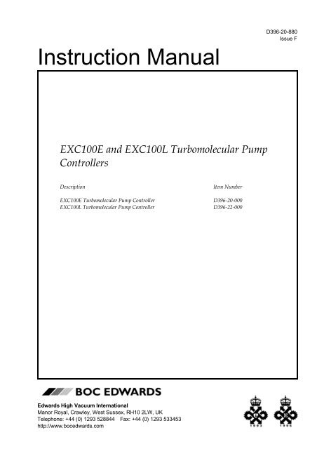
<strong>D396</strong>-<strong>20</strong>-<strong>880</strong><br />
Issue F<br />
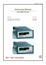
Instruction Manual<br />
<strong>EXC100E</strong> and EXC100L Turbomolecular Pump<br />
Controllers<br />
Description<br />
<strong>EXC100E</strong> Turbomolecular Pump Controller<br />
EXC100L Turbomolecular Pump Controller<br />
Item Number<br />
<strong>D396</strong>-<strong>20</strong>-000<br />
<strong>D396</strong>-22-000<br />
Edwards High Vacuum International<br />
Manor Royal, Crawley, West Sussex, RH10 2LW, UK<br />
Telephone: +44 (0) 1293 528844 Fax: +44 (0) 1293 533453<br />
http://www.bocedwards.com
CONTENTS<br />
Section Title Page<br />
1 INTRODUCTION 1<br />
1.1 Scope and definitions 1<br />
1.2 Description 2<br />
1.3 Connection of an Active gauge 3<br />
1.4 Logic interface 3<br />
1.4.1 Introduction 3<br />
1.4.2 Electrical supplies 4<br />
1.4.3 Control inputs 4<br />
1.4.4 Status outputs 4<br />
1.4.5 Analogue outputs 5<br />
1.5 Vent-valve control 5<br />
1.5.1 Introduction 5<br />
1.5.2 Vent on Stop 6<br />
1.6 Controller Fail conditions 6<br />
1.6.1 General 6<br />
1.6.2 Internal Timer 7<br />
2 TECHNICAL DATA 9<br />
2.1 Operating and storage data 9<br />
2.2 Mechanical data 9<br />
2.3 Electrical supply 9<br />
2.4 EXT pump electrical output data 9<br />
2.5 Logic interface 10<br />
2.6 Factory settings 10<br />
2.7 Electrical connectors 10<br />
DBW 5840-97<br />
3 INSTALLATION 12<br />
3.1 Unpack and inspect 12<br />
3.2 Configure the Controller 12<br />
3.2.1 Introduction 12<br />
3.2.2 Select speed or power analogue output 12<br />
3.2.3 Enable/disable the Internal Timer to monitor low pump speed 14<br />
3.2.4 Vent options 14<br />
3.3 Fit the Controller 15<br />
3.4 Introduction to Controller electrical connections 15<br />
3.5 Connect the electrical supply 18<br />
3.6 Connect additional earth (ground) bonding (if required) 18<br />
3.7 Connect the EXT pump 19<br />
3.8 Connect an AIM Active Inverted Magnetron gauge (optional) 19<br />
3.9 Connect the logic interface to your equipment 19<br />
3.9.1 Introduction 19<br />
3.9.2 Connect a vacuum gauge to the logic interface <strong>20</strong><br />
3.10 Adjust the Normal speed <strong>20</strong><br />
3.11 Adjust the Internal Timer <strong>20</strong><br />
EXC Turbomolecular Pump Controllers<br />
i
Section Title Page<br />
4 OPERATION 22<br />
4.1 Start-up 22<br />
4.2 Standby 22<br />
4.3 Operation with high inlet pressure 22<br />
4.4 Operation with high pump temperature 23<br />
4.5 Normal shutdown 23<br />
4.6 Automatic shutdown after Fail condition 23<br />
4.7 Reset the Controller after Fail condition 23<br />
4.10 Electrical supply failure 24<br />
5 MAINTENANCE 25<br />
5.1 Safety 25<br />
5.2 Replace a fuse 25<br />
5.2.1 Introduction 25<br />
5.2.2 Replace the electrical supply fuse 25<br />
5.3 Clean the Controller 25<br />
5.4 Fault finding 25<br />
6 STORAGE AND DISPOSAL 26<br />
6.1 Storage 26<br />
6.2 Disposal 26<br />
7 SERVICE, SPARES AND ACCESSORIES 27<br />
7.1 Introduction 27<br />
7.2 Service 27<br />
7.3 Accessories 27<br />
7.3.1 Electrical supply cable 27<br />
7.3.2 Pump-to-<strong>controller</strong> cable 28<br />
7.3.3 BX bakeout band 28<br />
7.3.4 TAV vent-valve 28<br />
7.3.5 ACX air-cooler 29<br />
7.3.6 Active vacuum gauges 29<br />
8 ENGINEERING DIAGRAMS 29<br />
RETURN OF BOC EDWARDS EQUIPMENT<br />
ii<br />
EXC Turbomolecular Pump Controllers
Illustrations<br />
Figure Title Page<br />
1 Rear panel of the Controller (<strong>EXC100E</strong> shown) 8<br />
2 Dimensions (mm): <strong>EXC100E</strong> shown 11<br />
3 Reconfigure the Controller (EXC100L shown) 13<br />
4 Schematic diagram of Controller electrical connections 17<br />
5 Normal Speed and Internal Timer potentiometers (EXC100L shown) 21<br />
6 EXC Controller to EXT pump connections 30<br />
7 Active Gauge connector 31<br />
Tables<br />
Table Title Page<br />
1 Configuration links 12<br />
2 Selection of vent-valve control options 14<br />
3 Logic interface pins 16<br />
4 Electrical supply cable wires 18<br />
5 APG to logic interface connections <strong>20</strong><br />
6 Active Gauge connector pins 31<br />
Associated Publications<br />
Publication title Publication Number<br />
EXT Pump Accessories<br />
EXT70 and EXT250 Turbomolecular pumps<br />
EXT351 and EXT501 Turbomolecular Pumps<br />
B580-66-<strong>880</strong><br />
B722-01-<strong>880</strong><br />
B727-<strong>20</strong>-<strong>880</strong><br />
EXC Turbomolecular Pump Controllers<br />
iii
iv<br />
EXC Turbomolecular Pump Controllers
1 INTRODUCTION<br />
1.1 Scope and definitions<br />
This manual provides installation, operation and maintenance instructions for the BOC Edwards<br />
<strong>EXC100E</strong> and EXC100L Turbomolecular Pump Controllers. You must use the Controller as<br />
specified in this manual.<br />
Read this manual before you install and operate the Controller. Important safety information is<br />
highlighted as WARNING and CAUTION instructions; you must obey these instructions. The<br />
use of WARNINGS and CAUTIONS is defined below.<br />
WARNING<br />
Warnings are given where failure to observe the instruction could result in injury or death<br />
to people.<br />
CAUTION<br />
Cautions are given where failure to observe the instruction could result in damage to the<br />
equipment, associated equipment or process.<br />
The units used throughout this manual conform to the SI international system of units of<br />
measurement.<br />
In accordance with the recommendations of IEC1010, the following warning symbols appear on<br />
the Controller.<br />
Caution - refer to accompanying documents<br />
Caution - risk of electric shock<br />
Protective conductor terminal<br />
Direct current only<br />
EXC Turbomolecular Pump Controllers 1
1.2 Description<br />
The EXC Controller generates the electrical supply and the control signals necessary to operate<br />
an EXT pump and its accessories. Refer to Section 2 for compatible EXT pumps.<br />
The Controller has a high-efficiency, auto-ranging power supply which adjusts itself to any<br />
external electrical supply in the specified voltage range (refer to Section 2). The power supply<br />
converts the single-phase electrical supply into a regulated d.c. electrical supply to control the<br />
operation of the EXT pump. The pump has three Hall effect devices which operate as rotor<br />
position sensors. These sensors ensure that the drive current is correctly switched to the<br />
phase-windings of the pump-motor . The Hall effect devices also generate a speed signal which<br />
the Controller uses to regulate the rotational speed of the pump.<br />
The Controller has a secondary regenerative supply which uses the d.c. motor of the EXT pump<br />
as a generator. If the electrical supply fails, the regenerative supply provides the Controller with<br />
a back-up source of power without the need for batteries. The Controller uses the regenerative<br />
supply to maintain the electrical supplies to the vent-valve, air-cooler and AIM gauge (if<br />
connected) until the pump speed falls to below 50% of full rotational speed (see Section 1.5.2).<br />
The Controllers have a number of control features which limit the power supplied to the EXT<br />
pump in the event of sustained high pressure or temperature:<br />
• If the EXT pump inlet pressure rises, the power supplied to the pump-motor increases to<br />
counteract the gas frictional load. The pump rotational speed remains constant until the<br />
Controller peak power level is reached; beyond this power level, the speed of the pump<br />
starts to reduce. If the pump speed falls to below 50% of its full rotational speed, the<br />
Controller may trip into Fail condition; this depends on how you have configured the<br />
Controller (see Section 1.6.2).<br />
• If the Controller detects that its temperature or the pump temperature is too high, it reduces<br />
the power supplied to the pump-motor; the pump may not therefore be able to maintain full<br />
rotational speed if it is too hot. If the pump speed falls to below 50% of its full rotational<br />
speed, the Controller may trip into Fail condition; this depends on how you have configured<br />
the Controller (see Section 1.6.2).<br />
The Controller has no front-panel controls and can only be operated through the logic interface.<br />
To operate the EXT pump, you must therefore connect the Controller to your own control<br />
equipment. Alternatively, you can configure the mating-plug for the logic interface connector<br />
so that the EXT pump starts to operate as soon as the electrical supply to the Controller is<br />
switched on: refer to Section 3.9.<br />
The rear-panel of the Controller has a Normal LED (Figure 1, item 6). The LED is on whenever<br />
the TMP Normal status output signal is low: refer to Section 1.4.4.<br />
The EXC100L Controller has an integral pump-to-<strong>controller</strong> cable. The <strong>EXC100E</strong> Controller has<br />
a mating connector suitable for a pump-to-<strong>controller</strong> cable accessory (not supplied): refer to<br />
Section 7.<br />
2 EXC Turbomolecular Pump Controllers
1.3 Connection of an Active gauge<br />
Note: The Controller contains a regenerative power supply which maintains the electrical supply to the<br />
AIM gauge in the event of a failure of the external electrical supply to the Controller (see<br />
Section 1.2).<br />
You can connect an BOC Edwards AIM Active Inverted Magnetron Gauge directly to the active<br />
gauge connector on the Controller and use the Controller TMP Normal signal to switch the gauge<br />
on. This allows you to control the AIM Gauge without the need to use an additional high<br />
pressure gauge (and its associated control equipment) to interlock the operation of the AIM<br />
Gauge to system pressure. Refer to Section 3.8 for details about how to connect an AIM gauge<br />
to the Controller.<br />
If you want to use another type of gauge, you must connect the gauge to the Controller through<br />
the logic interface: refer to Section 3.9.<br />
1.4 Logic interface<br />
1.4.1 Introduction<br />
The rear panel of the Controller has a 15-way logic interface connector (Figure 1, item 4) which<br />
you can use to connect the Controller to your own equipment.<br />
Signals on the logic interface are of four types:<br />
• Electrical supplies These are electrical supplies for optional accessories connected to<br />
your pump, such as the vent-valve and the air-cooler.<br />
• Control inputs These are switch-type input signals which are used to control the<br />
operation of the EXT pump.<br />
• Status outputs These output signals identify the status of the pump and the<br />
Controller.<br />
• Analogue output The Controller can be configured to provide a speed output or a<br />
power output. This output gives an indication of the EXT pump<br />
speed or power consumption.<br />
Refer to Table 3 and to Figure 4 for detailed information about the logic interface pins and their<br />
uses. A general description of the logic interface connections follows.<br />
EXC Turbomolecular Pump Controllers 3
1.4.2 Electrical supplies<br />
Two nominal 24 V supplies are provided, as described below:<br />
Vent-valve supply<br />
This electrical supply is provided to operate a vent-valve fitted to your EXT pump or vacuum<br />
system. The Controller automatically opens the valve when the speed of the pump falls to below<br />
50% of full rotational speed. You can also configure the Controller to operate the valve in other<br />
specific conditions: refer to Sections 1.5 and 3.2.<br />
Air-cooler supply<br />
This electrical supply is provided to operate an ACX air-cooler fitted to your EXT pump. The<br />
electrical supply is on whenever the Controller is on. Alternatively, if your pump is<br />
water-cooled, you can use this supply to operate a solenoid-valve to control the flow of water<br />
through the water-cooler.<br />
1.4.3 Control inputs<br />
You can use these inputs to control the operation of the EXT pump. The input signals are<br />
switch-type signals; you link (close) two pins on the logic interface when you want to set the<br />
required signal and you do not link (open) the pins when you do not want to set the signal. The<br />
input signals are as follows:<br />
Start/Stop<br />
Use the Start/Stop input to Start and Stop the EXT pump. To Start the pump, you must close<br />
the Start/Stop input. To Stop the pump, you must open the input (refer to Sections 4.1 and 4.5).<br />
Standby<br />
Close the Standby input to select pump Standby (refer to Section 4.2).<br />
1.4.4 Status outputs<br />
The Controller provides Normal, Fail and Pump On status output signals (TMP Normal, TMP<br />
Fail and TMP On) through open collector transistor outputs on the logic interface connector.<br />
These signals can be used to control devices in the pumping system or to provide remote status<br />
output signals. The signals operate as described below.<br />
TMP Normal<br />
TMP Normal is normally high and goes low when the EXT pump reaches its ’Normal’ speed.<br />
The Normal speed is determined by a potentiometer on the side of the Controller. The Controller<br />
is supplied with the potentiometer adjusted so that Normal speed is 80% of full rotational speed.<br />
You can adjust the Normal speed as described in Section 3.10. The Normal LED on the rear panel<br />
of the Controller (Figure 1, item 6) is on when the TMP Normal signal is low.<br />
4 EXC Turbomolecular Pump Controllers
TMP Fail<br />
TMP Fail is normally low and goes high when the Controller trips into a Fail condition (see<br />
Section 1.6).<br />
TMP On<br />
The TMP On signal mimics the operation of the vent-valve. If you select Vent On Stop (see<br />
Section 1.5.2), TMP On is normally high and goes low when the electrical supply to the EXT<br />
pump is switched on by the Controller.<br />
1.4.5 Analogue output<br />
The Controller has a single analogue output signal, which can be configured to indicate either<br />
Pump Speed or Pump Power consumption.<br />
The Controller is supplied configured so that the analogue output signal is proportional to EXT<br />
pump speed. Connect the output to a suitable meter or indicator to display the pump speed or<br />
connect the output to your control equipment (for example, to operate other components in the<br />
pumping system at a preset EXT pump speed).<br />
If required, you can configure the Controller so that the analogue output signal is proportional<br />
to the electrical power drawn by the EXT pump (see Sections 2.5 and 3.2.2). Connect the output<br />
to a suitable meter or indicator to display the pump power or connect the output to your control<br />
equipment.<br />
1.5 Vent-valve control<br />
1.5.1 Introduction<br />
Note: The factory settings for vent options are shown in Table 2.<br />
If the Controller electrical supply fails, the Controller maintains the electrical supply to the<br />
vent-valve until the pump speed falls to below 50% of full rotational speed, then the Controller<br />
switches off the vent-valve electrical supply. This feature of the Controller cannot be<br />
reconfigured.<br />
However, you can use the configuration links in the Controller (refer to Section 3.2.4) to select a<br />
combination of vent options in reponse to the Stop input signal and the TMP Fail output signal.<br />
When a selected vent option condition is detected, the Controller:<br />
• waits approximately two seconds, to allow a vacuum system isolation-valve (if fitted) to<br />
close,<br />
• then switches off the electrical supply to the vent-valve.<br />
EXC Turbomolecular Pump Controllers 5
1.5.2 Vent on Stop<br />
If Vent on Stop is selected when you switch the Controller on, the vent-valve electrical supply<br />
remains off until Start is selected. When Start is selected, the Controller switches the vent-valve<br />
electrical supply on. If Stop is then selected, the Controller switches the vent-valve electrical<br />
supply off again.<br />
If Vent on Stop is not selected when you switch the Controller on, the vent-valve electrical supply<br />
remains off until Start is selected. When Start is selected, the Controller switches the vent-valve<br />
electrical supply on. If Stop is then selected, the EXT pump will decelerate and the vent-valve<br />
electrical supply will remain on until the pump speed falls to below 50% of full rotational speed;<br />
the vent-valve electrical supply will then be switched off.<br />
1.5.3 Vent on Fail<br />
If Vent on Fail is selected, then the setting of the Vent on Stop option determines how the<br />
vent-valve is controlled in response to a Fail condition, as follows:<br />
• If you have selected Vent on Stop and a failure occurs, the Controller switches the vent-valve<br />
electrical supply off approximately two seconds after the the Fail condition is detected.<br />
• If you have not selected Vent on Stop, the EXT pump will decelerate and the vent-valve<br />
electrical supply will remain on until the pump speed falls to below 50% of full rotational<br />
speed; the vent-valve electrical supply will then be switched off.<br />
If you have not selected Vent on Fail, the electrical supply to the vent-valve will not be switched<br />
off when a Fail condition is detected.<br />
1.6 Controller Fail conditions<br />
1.6.1 General<br />
Note: If you enable the Internal Timer (see Sections 1.6.2 and 3.2.3), the Controller will trip into Fail<br />
condition only after the preset time has elapsed.<br />
The Controller will trip into Fail condition if either of the following occurs:<br />
• The EXT pump does not reach 50% of full rotational speed within a preset time after it starts<br />
(the time set by the adjustable Internal Timer: see Sections 1.6.2 and 3.2.3).<br />
• The EXT pump speed falls to below 50% of its full rotational speed.<br />
When the Controller trips into Fail condition, the electrical supply to the EXT pump-motor is<br />
switched off and the TMP Fail status output signal on the logic interface goes high. The operation<br />
of the vent-valve depends on how you have configured the Controller (refer to Sections 1.5 and<br />
3.2). To reset the Controller after a Fail condition has occurred, refer to Section 4.7.<br />
6 EXC Turbomolecular Pump Controllers
1.6.2 Internal Timer<br />
The Internal Timer has two functions:<br />
Firstly, when the EXT pump is started by the Controller, the Internal Timer in the Controller also<br />
starts. If the EXT pump does not reach 50% of full rotational speed within the preset time<br />
measured by the timer, the Controller will trip into Fail condition. This function cannot be<br />
disabled.<br />
Secondly, you can configure the Controller to enable or disable the Internal Timer if the pump<br />
speed falls during pump operation:<br />
• If you disable the Internal Timer, the Controller will trip into Fail condition as soon as the<br />
pump speed falls to below 50% of full rotational speed.<br />
• If you enable the Internal Timer, the Internal Timer will start as soon as the pump speed falls<br />
to below 50% of full rotational speed; the Controller will trip into Fail condition if the pump<br />
speed is still below 50% of full rotational speed at the end of the preset time.<br />
The Controller is supplied with the Internal Timer enabled and adjusted for a preset time of<br />
eight minutes. You can adjust the timer for your application: refer to Section 3.11.<br />
EXC Turbomolecular Pump Controllers 7
1. Electrical supply connector<br />
2. Earth (ground) stud<br />
3. EXT pump connector *<br />
4. Logic interface connector<br />
5. Active gauge connector<br />
6. Normal LED<br />
* <strong>EXC100E</strong> only; the EXC100L has an<br />
integral pump-to-<strong>controller</strong> cable<br />
Figure 1 - Rear panel of the Controller (<strong>EXC100E</strong> shown)<br />
8 EXC Turbomolecular Pump Controllers
2 TECHNICAL DATA<br />
2.1 Operating and storage data<br />
Ambient operating temperature range 0 to 40 o C<br />
Ambient storage temperature range<br />
-<strong>20</strong> to 70 o C<br />
Maximum ambient operating humidity 10 to 95% RH (non-condensing to DIN 40040)<br />
Maximum operating altitude<br />
3000 m<br />
Cooling<br />
Natural convection<br />
2.2 Mechanical data<br />
Dimensions See Figure 2<br />
Mass<br />
<strong>EXC100E</strong><br />
0.8 kg<br />
EXC100L<br />
1.0 kg<br />
Enclosure protection<br />
IP<strong>20</strong> (as defined by IEC529)<br />
Pollution degree IEC664, category 2<br />
2.3 Electrical data<br />
Electrical supply<br />
Voltage<br />
90 to 264 V a.c., single-phase<br />
Frequency<br />
47 to 63 Hz<br />
Maximum input power<br />
2<strong>20</strong> VA<br />
Peak inrush current<br />
11 A at 110 V a.c.<br />
40 A at 240 V a.c.<br />
Fuse rating<br />
2 A, type T <strong>20</strong> mm<br />
Over-voltage transients IEC664, category 2<br />
Radiated electromagnetic emission<br />
EN50081-1<br />
Electromagnetic immunity<br />
EN50082-2<br />
2.4 EXT pump electrical output data<br />
Compatible EXT pumps<br />
Maximum continuous output power<br />
Maximum output voltage<br />
Switching frequency<br />
Nominal output frequency<br />
Maximum output frequency<br />
Standby frequency<br />
EXT70, EXT250, EXT351<br />
80 W<br />
53 V a.c. r.m.s.<br />
32 kHz<br />
600 Hz to 1.5 kHz<br />
1.07 x nominal<br />
70% of nominal<br />
EXC Turbomolecular Pump Controllers 9
2.5 Logic interface<br />
Remote control signals<br />
Control voltage: low (close)<br />
< 0.8 V d.c.<br />
Control voltage: high (open)<br />
4 to 24 V d.c.<br />
Maximum input current (at 24 V) 80 µA<br />
Maximum output current (at 0 V d.c.) 160 µA<br />
Air-cooler electrical supply<br />
Voltage range<br />
+<strong>20</strong> to +26 V d.c.<br />
Maximum output current<br />
150 mA<br />
Vent-valve electrical supply<br />
Voltage range<br />
+16 to +26 V d.c.<br />
Maximum output current<br />
80 mA<br />
Analogue output<br />
Output voltage<br />
0 to +10 V d.c. proportional to speed or power:<br />
0 to 10 V ≅ 0 to 100% of pump speed, or<br />
0 to 10 V ≅ 0 to 80 W motor power<br />
Maximum output current<br />
5 mA<br />
TMP Normal and TMP Fail status outputs<br />
Maximum output voltage (high)<br />
26 V d.c.<br />
Maximum output current<br />
Vout (low) ≥0.8 V<br />
<strong>20</strong> mA<br />
Vout (low)
A<br />
B<br />
C<br />
Rear view<br />
Top view<br />
Side view<br />
1. Clearance for ventilation<br />
2. Clearance for cables<br />
3. Optional mounting plate<br />
Figure 2 - Dimensions (mm): <strong>EXC100E</strong> shown<br />
EXC Turbomolecular Pump Controllers 11
3 INSTALLATION<br />
3.1 Unpack and inspect<br />
Remove all packing materials and check the Controller. If the Controller is damaged, notify your<br />
supplier and the carrier in writing within three days; state the Item Number of the Controller<br />
together with your order number and your supplier’s invoice number. Retain all packing<br />
materials for inspection. Do not use the Controller if it is damaged.<br />
If the Controller is not to be used immediately, store the Controller in suitable conditions, as<br />
described in Section 6.<br />
3.2 Configure the Controller<br />
3.2.1 Introduction<br />
The Controller has four links which can be used to configure the Controller for your application:<br />
see Table 1. Each link can be in one of two positions as shown in Figure 3 and described in<br />
Sections 3.2.2 and 3.2.4.<br />
If you want to reconfigure the Controller, undo and remove the two screws (Figure 3, items 1)<br />
and remove the top cover (2) of the Controller to access the links. Use the links as described in<br />
the following sections.<br />
Link<br />
LK1<br />
LK4<br />
LK5<br />
LK6<br />
Use<br />
Select speed or power analogue output<br />
Enable or disable the Internal Timer<br />
Select Vent on Stop or no Vent on Stop<br />
Select Vent on Fail or no Vent on Fail<br />
Table 1 - Configuration links<br />
3.2.2 Select speed or power analogue output<br />
Note: The Controller is supplied with link LK1 configured to provide the pump speed analogue output<br />
signal on the logic interface.<br />
Refer to Figure 3. To select the pump speed analogue output signal on the logic interface, insert<br />
link LK1 in the upper position (5).<br />
To select the pump power analogue output signal on the logic interface, insert link LK1 in the<br />
lower position (6).<br />
12 EXC Turbomolecular Pump Controllers
1. Screw<br />
2. Top cover<br />
3. Fuse holder<br />
4. Speed/power link: LK1<br />
5. Link LK1 in speed configuration<br />
6. Link LK1 in power configuration<br />
7. Link LK6 not active: Vent On Fail not selected<br />
8. Link LK6 active: Vent On Fail selected<br />
9. Link LK5 not active: Vent On Stop not selected<br />
10. Link LK5 active: Vent On Stop selected<br />
11. Link LK4 not active: Timer disabled<br />
12. Link LK4 active: Timer enabled<br />
Figure 3 - Reconfigure the Controller (EXC100L shown)<br />
EXC Turbomolecular Pump Controllers 13
3.2.3 Enable/disable the Internal Timer to monitor low pump speed<br />
Notes: If you pump a high gas load when the Internal Timer is enabled (link LK4 in the enabled position:<br />
Figure 3, item 12), the EXT pump may stall before the Controller trips into Fail condition. Ensure<br />
that oil which backstreams from the backing pipeline will not adversely affect your process. Disable<br />
the Internal Timer to provide the greatest protection against backstreaming if a Fail condition<br />
occurs.<br />
The Controller is supplied with the Internal Timer enabled.<br />
Set link LK4 to enable or disable the use of the Internal Timer when the pump rotational speed<br />
falls to below 50% of full rotational speed during operation (see Section 1.6.2):<br />
• Insert link LK4 in the active position (Figure 3, item 12) to enable the Timer. The Internal<br />
Timer will then start as soon as the pump rotational speed falls to below 50% of full rotational<br />
speed. If the pump speed remains below 50% of full rotational speed after the preset time,<br />
the Controller will trip into the Fail condition.<br />
• Insert link LK4 in the not active position (Figure 3, item 11) to disable the Timer. The<br />
Controller will then trip into the Fail condition as soon as the pump rotational speed falls to<br />
below 50% of full rotational speed.<br />
3.2.4 Vent options<br />
Links LK5 and LK6 are used to select the vent-valve control options (refer to Section 1.5). Each<br />
of the links can be in one of two positions: the link not active position and the link active position.<br />
Position the links to select the required vent options as shown in Table 2.<br />
Note however, that if the electrical supply to the Controller fails, the Controller will always<br />
switch off the electrical supply to the vent-valve when the EXT pump speed falls to below 50%<br />
of full speed (see Section 1.6.1).<br />
LK6 (Vent on Fail)<br />
not active<br />
not active<br />
Link positions<br />
LK5 (Vent on Stop)<br />
not active<br />
active<br />
Vent options<br />
Vent when the EXT pump speed falls to<br />
50% of full speed after Stop is selected or a<br />
Fail condition is detected.<br />
Vent on Stop; vent when the EXT pump<br />
speed falls to 50% of full speed after a Fail<br />
condition is detected.<br />
active * not active *<br />
Vent on Fail; vent when the EXT pump<br />
speed falls to 50% of full speed after Stop<br />
is selected.<br />
active active Vent on Fail and vent on Stop.<br />
* Link positions as supplied.<br />
Table 2 - Selection of vent-valve control options<br />
14 EXC Turbomolecular Pump Controllers
3.3 Fit the Controller<br />
WARNING<br />
The Controller contains electrolytic capacitors and, under certain fault conditions, may<br />
emit dangerous fumes. Ensure that the Controller is operated in a well-ventilated area.<br />
CAUTION<br />
You must allow the correct clearances for air circulation and you must fit the Controller<br />
onto a thermally conductive surface. If you do not, the performance and reliability of the<br />
Controller may be affected at high operating temperatures.<br />
You must fit the Controller in a rack or cabinet. You can operate the Controller in a horizontal<br />
position or in a vertical position with the side vents at the top.<br />
When you fit the Controller, you must allow 15 mm clearance at the sides of the Controller for<br />
air circulation and you must allow 75 mm clearance at the back of the Controller for the cables.<br />
You must firmly fit the Controller onto a thermally conductive material, for example aluminium<br />
or steel. The location of the bottom panel fixing-holes are shown in Figure 2.<br />
3.4 Introduction to Controller electrical connections<br />
When you make the electrical connections to the Controller described in the following sections,<br />
refer to Table 3 for full details of the logic interface connections and refer to Figure 4 which shows<br />
a schematic diagram of the electrical connections.<br />
You must provide suitable strain-relief on the cables which you fit to the Controller.<br />
EXC Turbomolecular Pump Controllers 15
Pin number Signal Polarity* Signal type<br />
1 TMP On (low when pump is on) N/A<br />
7 TMP Fail (high when fail condition exists) N/A<br />
8 Status output common N/A<br />
Status<br />
outputs<br />
15 TMP Normal (low when pump is at Normal speed) ✝ N/A<br />
3<br />
+ Control<br />
Start/Stop: Close for Start<br />
input<br />
4 -<br />
11<br />
+ Control<br />
Standby: Close for Standby<br />
input<br />
4 -<br />
10 RFI screen N/A N/A<br />
5 Vent-valve electrical supply: 24 V +<br />
13 Vent-valve control ◆ -<br />
6 Air-cooler electrical supply: 24 V +<br />
14 Air-cooler electrical supply: 0 V -<br />
Supply<br />
Supply<br />
9<br />
+ Analogue<br />
Pump speed or power<br />
output<br />
2 -<br />
* + = positive, - = negative, N/A = not applicable.<br />
✝ This output is only TTL compatible when the current drawn is < 1 mA. Refer to Section 2 for more information.<br />
◆ This supply line is raised to +24 V to de-energise the valve coil and vent the system.<br />
Table 3 - Logic interface pins<br />
16 EXC Turbomolecular Pump Controllers
A<br />
Vacuum and control system<br />
1. External electrical supply<br />
9. TMP Normal output (normally open)*<br />
B<br />
EXC Controller<br />
2. Electrical supply connector<br />
10. Remote indicator equipment<br />
3. Earth (ground)<br />
11. Air-cooler<br />
L<br />
Live electrical supply<br />
4. AIM active gauge<br />
12. Vent-valve<br />
N<br />
Neutral electrical supply<br />
5. Active gauge connector<br />
13. External Standby switch<br />
E<br />
Earth (ground) electrical supply<br />
6. Logic interface connector<br />
14. External Start/Stop switch<br />
7. Vent-valve control<br />
15. Speed/power indicator<br />
(normally open)*<br />
8. TMP Fail (normally closed)*<br />
* These are solid-state switches in the Controller<br />
Figure 4 - Schematic diagram of Controller electrical connections<br />
EXC Turbomolecular Pump Controllers 17
3.5 Connect the electrical supply<br />
WARNING<br />
High voltages exist in the Controller when it is operating. Ensure that the Controller is<br />
earthed (grounded) and observe all appropriate safety precautions for the safe installation<br />
and handling of electrical equipment. If you do not, there will be a danger of injury or<br />
death to people by electric shock.<br />
You must use a suitable electrical supply cable to connect the Controller to the electrical supply.<br />
An electrical supply cable is not supplied with the Controller, but is available as an accessory:<br />
refer to Section 7.<br />
1. Connect the wires at one end of the electrical supply cable to a suitably rated and fused<br />
electrical supply; if required, connect the wires to a suitably rated plug. Connect the wires<br />
as shown in Table 4.<br />
Wire colour<br />
Green/yellow<br />
Brown<br />
Blue<br />
Use<br />
Earth (ground)<br />
Live (line)<br />
Neutral<br />
Table 4 - Electrical supply cable wires<br />
2. Fit the connector on the other end of the electrical supply cable to the electrical supply<br />
connector on the front of the Controller (see Figure 1).<br />
3.6 Connect additional earth (ground) bonding (if required)<br />
Protective earthing (grounding) for electrical safety of the Controller, EXT pump and accessories<br />
is provided by the electrical supply cables and connectors and the pump-to-<strong>controller</strong> cable.<br />
However, additional earth (ground) bonding may be required to improve the reliability of the<br />
system by reducing any effects of RFI (radio frequency interference), particularly if the vacuum<br />
system is prone to high voltage discharges or other radio frequency emissions.<br />
Use good EMC (electromagnetic compatibility) practices and take note of the following EMC<br />
earthing (grounding) guidelines to reduce the susceptibility of the system to RFI:<br />
• Connect the Controller, the EXT pump and the vacuum chamber to a common earth<br />
(ground) point on the pumping system; this ’star’ earth (ground) is typically in the electrical<br />
power distribution box.<br />
• Clamp the Controller earthing (grounding) terminal between the two lock-nuts provided<br />
on the earth (ground) stud on the rear panel of the Controller.<br />
• Use suitable heavy duty cable or braid to ensure a low impedance bond to the earth (ground)<br />
point (typically less than 0.1 Ω for each leg of the star).<br />
• Use screened cable for all wiring to the logic interface connector. (The TAV5 vent-valve and<br />
the ACX Air Cooler accessories are provided with screened cable.) Connect each screen to<br />
the Controller earth (ground) stud to ensure that they are properly earthed (grounded).<br />
18 EXC Turbomolecular Pump Controllers
3.7 Connect the EXT pump<br />
If you have an EXC100L Controller, fit the connector on the end of the integral pump-to<strong>controller</strong><br />
cable to the connector on the EXT pump.<br />
If you have an <strong>EXC100E</strong> Controller, use a pump-to-<strong>controller</strong> cable (not supplied) to connect the<br />
Controller to the EXT pump. Fit the connectors on the ends of the cable to the appropriate<br />
mating-halves on the rear of the Controller and on the EXT pump.<br />
3.8 Connect an AIM Active Inverted Magnetron gauge (optional)<br />
Use an BOC Edwards Active gauge cable (available as an accessory: see Section 7) to connect an<br />
BOC Edwards AIM Active Inverted Magnetron Gauge to the Controller through the active gauge<br />
connector (Figure 1, item 5) on the rear of the Controller.<br />
If you want to connect another type of gauge to the Controller, connect the gauge to the logic<br />
interface: refer to Section 3.9.<br />
3.9 Connect the logic interface to your equipment<br />
3.9.1 Introduction<br />
CAUTION<br />
Do not earth (ground) the logic interface 0 V line (pins 13 and 14). If you do, you will<br />
provide an earth (ground) return path for any electrical fault in the pump-motor and this<br />
could damage the Controller or your control equipment.<br />
Use the appropriate pins on a suitable mating-plug (not supplied) for the logic interface<br />
connector to connect your control equipment and accessories to the Controller, as described in<br />
the previous sections and as shown in Table 3 and Figure 4. We recommend that you use wire<br />
of 0.24 mm 2 (or smaller) cross-sectional area.<br />
Alternatively, if you do not connect the Controller to your control equipment, link pins 3 and 4<br />
in the mating-plug. The EXT pump will then start to operate as soon as the electrical supply to<br />
the Controller is switched on and the pump will stop when the electrical supply to the Controller<br />
is switched off.<br />
EXC Turbomolecular Pump Controllers 19
3.9.2 Connect a vacuum gauge to the logic interface<br />
You can connect an BOC Edwards APG Active Pirani Gauge to the Controller so that the setpoint<br />
output of the gauge sets the Start/Stop input on the logic interface, to switch on the EXT pump.<br />
We recommend that you use the following procedure:<br />
1. Fit an active gauge connector to a suitable break-out box.<br />
2. Connect wires from the break-out box to the logic interface on the Controller, as shown in<br />
Table 5.<br />
APG connector<br />
pin number<br />
1<br />
2<br />
3<br />
4<br />
5<br />
6<br />
Logic interface<br />
pin number<br />
6<br />
14<br />
-<br />
-<br />
-<br />
3<br />
Table 5 - APG to logic interface connections<br />
If you want to connect another type of gauge to the Controller, refer to the instruction manual<br />
supplied with your gauge for information on the electrical connections to the gauge.<br />
3.10 Adjust the Normal speed<br />
Note: If you set the Normal speed to be more than 70% of full rotational speed, the TMP Normal output<br />
will go high when you select Standby. The Controller is supplied with the Normal speed set to<br />
80% of full rotational speed.<br />
You can adjust the Normal speed (at which the TMP Normal output goes low: see Section 1.4.4)<br />
between 65 and 95% of full rotational speed.<br />
Refer to Figure 5. To adjust the Normal speed, use a small screwdriver to turn the SETPOINT<br />
potentiometer (A). Figure 5 also shows the approximate Normal speed settings for different<br />
potentiometer adjustments.<br />
3.11 Adjust the Internal Timer<br />
The Internal Timer can be adjusted between approximately 1 and 30 minutes. The Controller is<br />
supplied with the Internal Timer adjusted to eight minutes (see Section 1.6.2).<br />
To adjust the Internal Timer, use a small screwdriver to turn the TIMER potentiometer (B).<br />
Figure 5 also shows the approximate timer settings for different potentiometer adjustments;<br />
these settings are only approximate. If the timer setting is critical for your application, you must<br />
check the time and readjust the potentiometer as necessary, until the correct time is obtained.<br />
<strong>20</strong> EXC Turbomolecular Pump Controllers
A<br />
B<br />
Normal speed potentiometer<br />
Timer potentiometer<br />
Figure 5 - Normal Speed and Internal Timer potentiometers (EXC100L shown)<br />
EXC Turbomolecular Pump Controllers 21
4 OPERATION<br />
4.1 Start-up<br />
Notes: If you wish, you can start the backing pump and the EXT pump at the same time; the EXT pump<br />
will not be damaged and can operate as an effective baffle. However, if the system pressure remains<br />
too high for the EXT pump to reach 50% of full rotational speed in the preset time (set by the<br />
Internal Timer), the Controller will trip into Fail condition: refer to Section 3.11 for adjustment<br />
of the Internal Timer.<br />
The following sections assume that you will connect the Controller to your control equipment and<br />
use the control input signals on the logic interface connector to operate the pumping system.<br />
When Start is selected, the Controller will switch on the electrical supply to the EXT pump and<br />
the pump rotor will start to accelerate.<br />
Use the following procedure to start up your system. This procedure assumes that you will<br />
manually operate the vent-valve and the backing pump, however you can configure the<br />
Controller to automatically operate the vent-valve (refer to Section 3.2.4).<br />
1. Close the vent-valve (if fitted).<br />
2. Start the backing pump.<br />
3. Start the EXT pump: close the Start/Stop input on the logic interface (see Section 1.4.3).<br />
4.2 Standby<br />
To select Standby, close the Standby input on the logic interface (that is, ensure that the<br />
appropriate pins are linked: see Section 1.4.3).<br />
If you select Standby when the pump is operating, the speed of the pump will be reduced to the<br />
Standby speed. If you select Standby before you switch the pump on, the pump will run up to<br />
Standby speed, not up to full speed.<br />
4.3 Operation with high inlet pressure<br />
If the EXT pump inlet pressure rises, the power supplied by the Controller to the pump-motor<br />
will increase to counteract the gas frictional load. The pump rotational speed will remain<br />
constant until the Controller peak power level is reached; beyond this power level, the speed of<br />
the pump will start to reduce.<br />
If the pump speed falls to below 50% of its full rotational speed, the Controller may trip into Fail<br />
condition; this depends on how you have configured the Controller (see Sections 1.6 and 3.2).<br />
Refer to the EXT pump instruction manual for the maximum allowable inlet pressure, and refer<br />
to Section 2.4 for the maximum Controller output power.<br />
22 EXC Turbomolecular Pump Controllers
4.4 Operation with high pump temperature<br />
Temperature sensors in the Controller and the EXT pump are monitored by the Controller. If<br />
the Controller detects that the pump temperature is too high, the power supplied to the<br />
pump-motor is reduced; the pump may not therefore be able to maintain full rotational speed<br />
if it is too hot.<br />
If the pump speed falls to below 50% of its full rotational speed, the Controller may immediately<br />
trip into Fail condition, or trip into Fail condition after a set time; this depends on how you have<br />
configured the Controller (see Sections 1.6 and 3.2).<br />
Refer to the EXT pump instruction manual for the pump operating temperature ranges.<br />
4.5 Normal shutdown<br />
Use the following procedure to shut down your system. This procedure assumes that you will<br />
manually operate the vent-valve and the backing pump, however you can configure the<br />
Controller to automatically operate the vent-valve (refer to Section 3.2.4). Refer to the Instruction<br />
Manual for the EXT pump for details of the maximum allowable vent rate.<br />
1. Select Stop: open the Start/Stop input on the logic interface connector (see Section 1.4.3).<br />
2. Open the vent-valve before the EXT pump speed is below 50% of full rotational speed.<br />
3. Switch off the backing pump.<br />
4.6 Automatic shutdown after Fail condition<br />
WARNING<br />
If the Start/Stop control signal on the logic interface connector is set to Start, the Controller<br />
will automatically restart the EXT pump when the electrical supply is restored after an<br />
electrical supply failure. Ensure that people cannot be injured by the rotating rotor blades<br />
of the EXT pump.<br />
The Controller will automatically switch off the electrical supply to the EXT pump if the<br />
Controller trips into Fail condition (see Section 1.6).<br />
The operation of the vent-valve in all Fail conditions depends on how you have configured the<br />
Controller: refer to sections 1.6 and 3.2.<br />
4.7 Reset the Controller after Fail condition<br />
To reset a Fail condition, open the Start/Stop input on the logic interface for at least 300 ms and<br />
then close the input.<br />
EXC Turbomolecular Pump Controllers 23
4.8 Electrical supply failure<br />
If the electrical supply to the Controller fails when the EXT pump is rotating:<br />
• The motor of the EXT pump is used as a generator and the electrical supplies for the<br />
vent-valve, air-cooler and AIM gauge (if connected) and the associated control logic are<br />
maintained until the pump speed falls to 50% of full rotational speed, then the electrical<br />
supplies are switched off.<br />
• The Controller will then shut down.<br />
24 EXC Turbomolecular Pump Controllers
5 Maintenance<br />
5.1 Safety<br />
WARNING<br />
Obey the safety instructions given below and take note of appropriate precautions. If you<br />
do not, you can cause injury to people and damage to equipment.<br />
• A suitably trained and supervised technician must maintain the Controller.<br />
• Isolate the Controller and other components in the pumping system from the electrical<br />
supply so that they cannot be operated accidentally.<br />
• Dispose of components safely (see Section 6.2).<br />
5.2 Replace a fuse<br />
5.2.1 Introduction<br />
If the electrical supply fuse fails immediately after you have replaced it, determine the cause of<br />
the failure and rectify the fault before you use the Controller.<br />
5.2.2 Replace the electrical supply fuse<br />
1. Refer to Figure 3. Undo and remove the two screws (1) and remove the top cover (2) of the<br />
Controller.<br />
2. Remove the fuse holder (3), remove and discard the failed fuse.<br />
3. Insert a new fuse of the correct rating (refer to Section 2.3) and refit the fuse holder.<br />
4. Refit the top cover (2) and secure with the two screws (1).<br />
5.3 Clean the Controller<br />
If necessary, use a soft dry cloth to clean the exterior of the Controller.<br />
If you need to clean the interior of the Controller, we recommend that you return the Controller<br />
to your supplier or your nearest BOC Edwards Service Centre.<br />
5.4 Fault finding<br />
If the Controller shuts down because of Fail condition, refer to the appropriate sections of this<br />
manual to determine the cause of the Fail condition. If necessary, refer to the appropriate fault<br />
finding section of the instruction manual supplied with the EXT pump.<br />
EXC Turbomolecular Pump Controllers 25
6 STORAGE AND DISPOSAL<br />
6.1 Storage<br />
Fit protective covers over the electrical connections and store the Controller in clean dry<br />
conditions until required.<br />
When required for use, prepare and install the Controller as described in Section 3 of this manual.<br />
6.2 Disposal<br />
WARNING<br />
Do not incinerate the Controller. If you do, you may cause injury to people.<br />
Dispose of the Controller and any components safely in accordance with all local and national<br />
safety and environmental requirements.<br />
Do not incinerate the Controller. If the Controller is heated to very high temperatures, dangerous<br />
gases may be emitted and internal components may explode.<br />
26 EXC Turbomolecular Pump Controllers
7 SERVICE, SPARES AND ACCESSORIES<br />
7.1 Introduction<br />
BOC Edwards products, spares and accessories are available from BOC Edwards companies in<br />
Belgium, Brazil, Canada, France, Germany, Hong Kong, Italy, Japan, Korea, Switzerland, United<br />
Kingdom, U.S.A and a world-wide network of distributors. The majority of these centres employ<br />
Service Engineers who have undergone comprehensive BOC Edwards training courses.<br />
Order spare parts and accessories from your nearest BOC Edwards company or distributor.<br />
When you order, please state for each part required:<br />
• Model and Item Number of your equipment<br />
• Serial number (if any)<br />
• Item Number and description of the part.<br />
7.2 Service<br />
BOC Edwards products are supported by a world-wide network of BOC Edwards Service<br />
Centres. Each Service Centre offers a wide range of options including: equipment<br />
decontamination; service exchange; repair; rebuild and testing to factory specifications.<br />
Equipment which has been serviced, repaired or rebuilt is returned with a full warranty.<br />
Your local Service Centre can also provide BOC Edwards engineers to support on-site<br />
maintenance, service or repair of your equipment.<br />
For more information about service options, contact your nearest Service Centre or other BOC<br />
Edwards company.<br />
7.3 Accessories<br />
7.3.1 Electrical supply cable<br />
You must use a suitable elctrical supply cable to connect the Controller to your electrical supply.<br />
An electrical supply cable is not supplied with the Controller.<br />
Cable<br />
Electrical supply cable (2 m length, unterminated)<br />
Item Number<br />
D385-01-102<br />
EXC Turbomolecular Pump Controllers 27
7.3.2 Pump-to-<strong>controller</strong> cable<br />
A pump-to-<strong>controller</strong> cable must be used with each pump. It is not supplied with the EXT pump<br />
or with the <strong>EXC100E</strong> Controller. The following cables are available:<br />
Cable<br />
Pump-to-<strong>controller</strong> cable, 1 m<br />
Pump-to-<strong>controller</strong> cable, 3 m<br />
Pump-to-<strong>controller</strong> cable, 5 m<br />
Pump-to-<strong>controller</strong> cable (OEM *), 5 m<br />
Item Number<br />
<strong>D396</strong>-18-010<br />
<strong>D396</strong>-18-030<br />
<strong>D396</strong>-18-050<br />
<strong>D396</strong>-<strong>20</strong>-325<br />
* The OEM cable is supplied with a separate connector so that you can fit the cable through a bulkhead,<br />
if required.<br />
7.3.3 BX bakeout band<br />
A BX bakeout band accelerates the degassing of the pump to enable it to achieve lower pressures.<br />
It may also be used to protect the pump from condensation of contaminants. The bakeout bands<br />
are available in 110-1<strong>20</strong> V or 2<strong>20</strong>-240 V versions. You must provide an external electrical supply<br />
to power the bakeout band; you cannot power it from the Controller.<br />
Bakeout band Voltage Item Number<br />
BX70 110 V B580-52-040<br />
BX70 240 V B580-52-060<br />
BX250 110 V B580-52-041<br />
BX250 240 V B580-52-061<br />
BX351 110 V B580-52-042<br />
BX351 240 V B580-52-062<br />
7.3.4 TAV vent-valve<br />
A solenoid-operated vent-valve is available for system venting. The valve is 24 V d.c. 2 W,<br />
normally-open, and can be operated automatically from the EXC Controller. The solenoid-valve<br />
is fitted in place of the manual vent-valve, or alternatively can be fitted with an adaptor (supplied<br />
with the valve) and used with any suitable NW10 flanged port on your vacuum system.<br />
Vent-valve<br />
TAV5 vent-valve<br />
Item Number<br />
B580-66-010<br />
28 EXC Turbomolecular Pump Controllers
7.3.5 ACX air-cooler<br />
An ACX air-cooler can be fitted to the EXT pump and can be operated automatically from the<br />
Controller. However, please refer to Section 3 of the instruction manual for the EXT pump to<br />
check the suitability of air cooling in a particular application.<br />
Air-cooler<br />
ACX70<br />
ACX250<br />
ACX350/500<br />
Item Number<br />
B580-53-050<br />
B580-53-150<br />
B580-53-<strong>20</strong>0<br />
7.3.6 Active vacuum gauges<br />
Examples of suitable gauges and accessories which you can connect to the EXC Controllers are<br />
listed below. Note that you can only connect an AIM gauge directly to the active gauge connector<br />
on the Controller; you must connect other gauges through the logic interface: refer to Section 3.9.<br />
Description<br />
AIM-S-NW25 Active Inverted Magnetron Gauge<br />
AIM-SL-NW25 Active Inverted Magnetron Gauge<br />
APG-M-NW16 Active Pirani Gauge<br />
APG-L-NW16 Active Pirani Gauge<br />
ATC-E Active Thermocouple Gauge<br />
ATC-D 1 /8 inch NPT Thermocouple Gauge Tube<br />
ATC-M 1 /8 inch NPT Thermocouple Gauge Tube<br />
Active Gauge Cable, 0.5 m long<br />
Active Gauge Cable, 1 m long<br />
Active Gauge Cable, 3 m long<br />
Item Number<br />
D145-45-000<br />
D145-48-000<br />
D021-71-000<br />
D021-73-000<br />
D351-08-000<br />
D351-12-000<br />
D351-13-000<br />
D400-01-005<br />
D400-01-010<br />
D400-01-030<br />
8 ENGINEERING DIAGRAMS<br />
To assist in fault finding (refer to Section 5), the connections between the Controller and the EXT<br />
pump are shown in Figure 6.<br />
The Active Gauge connector (which is specific to the EXC Controller) is shown in Figure 7.<br />
EXC Turbomolecular Pump Controllers 29
A<br />
B<br />
C<br />
D<br />
EXT pump<br />
EXT connector on cable<br />
EXC connector on cable*<br />
EXC Controller<br />
1. DC motor<br />
2. Speed set resistor<br />
3. Hall effect device 1<br />
4. Hall effect device 2<br />
5. Hall effect device 3<br />
6. Pump temperature sensor<br />
* <strong>EXC100E</strong> <strong>controller</strong> only; the EXC100L has an integral cable<br />
Figure 6 - EXC Controller to EXT pump connections<br />
30 EXC Turbomolecular Pump Controllers
Figure 7 - Active gauge connector pins<br />
Pin Signal<br />
1 Power supply +24 V d.c.<br />
2 Power supply 0 V d.c.<br />
3 Not used<br />
4 Gauge identification signal<br />
5 Not used<br />
6 Not used<br />
7 TMP Normal status output<br />
8 Not used<br />
Table 6 - Active gauge connector pins<br />
EXC Turbomolecular Pump Controllers 31
32 EXC Turbomolecular Pump Controllers