ADC active digital controller user manual
ADC active digital controller user manual
ADC active digital controller user manual

You also want an ePaper? Increase the reach of your titles
YUMPU automatically turns print PDFs into web optimized ePapers that Google loves.
D395-90-880 Issue C Original<br />
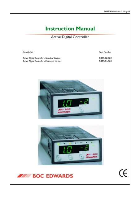
Instruction Manual<br />
Active Digital Controller<br />
Description<br />
Active Digital Controller - Standard Version<br />
Active Digital Controller - Enhanced Version<br />
Item Number<br />
D395-90-000<br />
D395-91-000
Active Digital Controller<br />
CONTENTS<br />
Section Title Page<br />
1 INTRODUCTION 1<br />
PAGE<br />
i<br />
1.1 Scope and definitions 1<br />
1.2 Product description 1<br />
2 TECHNICAL DATA 3<br />
2.1 Electrical data 3<br />
2.2 Operating and storage data 3<br />
2.3 Mechanical data 3<br />
2.4 Display 3<br />
2.5 Connections 4<br />
2.5.1 Active gauge connectors 4<br />
2.5.2 Analogue / relay connector (enhanced only) 5<br />
2.5.3 Serial communications (enhanced only) 6<br />
3 INSTALLATION 7<br />
3.1 Unpack and inspect 7<br />
3.2 Fitting the <strong>controller</strong> 7<br />
3.2.1 Bench-top mounting 7<br />
3.2.2 Panel mounting 8<br />
3.3 Rear panel description 9<br />
3.3.1 Connecting the electrical supply 9<br />
3.3.2 Connecting <strong>active</strong> gauges 9<br />
3.3.3 Connecting the analogue / relay connector (enhanced only) 10<br />
3.3.4 Connecting the serial interface (enhanced only) 10<br />
4 OPERATION 11<br />
4.1 Front panel description 11<br />
4.2 Power up 11<br />
4.3 Gauge identification 11<br />
4.4 Gauge display (standard) 12<br />
4.5 Menu structure (enhanced) 13<br />
4.5.1 Gauge pressure display 13<br />
4.5.2 Set-point adjustment 13<br />
4.5.3 Set-point 2 controlling gauge 14<br />
4.5.4 Gauge calibration 14<br />
4.5.5 Units selection 14<br />
4.6 RS232 operation (enhanced only) 15<br />
4.6.1 Message basics 15<br />
4.6.2 Commands 15<br />
4.6.3 Queries 16<br />
4.6.4 Responses 16<br />
4.7 Linking two <strong>ADC</strong>s (enhanced only) 16<br />
dcs/0139/0802<br />
Jun 06<br />
i<br />
Issue C
Active Digital Controller<br />
CONTENTS (continued)<br />
PAGE<br />
ii<br />
Section Title Page<br />
5 MAINTENANCE 17<br />
5.1 Safety 17<br />
5.2 Fault finding guide 17<br />
5.3 Cleaning the <strong>controller</strong> 18<br />
5.4 Software upgrade 18<br />
5.5 Calibration service 18<br />
6 STORAGE AND DISPOSAL 19<br />
6.1 Storage 19<br />
6.2 Disposal 19<br />
7 SPARES AND ACCESSORIES 20<br />
7.1 Introduction 20<br />
7.2 Accessories 20<br />
APPENDIX A 22<br />
APPENDIX B 24<br />
APPENDIX C 26<br />
INDEX 29<br />
RETURN OF BOC EDWARDS EQUIPMENT<br />
Issue C ii<br />
Jun 06
Active Digital Controller<br />
ILLUSTRATIONS<br />
Figure Title Page<br />
1 Pin connections for an 8-way FCC/RJ45 4<br />
2 Pin connections and pin-out for the analogue / relay connector 5<br />
3 Pin connections for the serial comms connector 6<br />
4 Bench mounted dimensions (mm) 7<br />
5 Panel cut-out required 8<br />
6 Panel mounting the <strong>ADC</strong> 8<br />
7 Rear panel connections 9<br />
8 IBM PC RS232 interface - 9-way 10<br />
9 IBM PC RS232 interface - 25-way 10<br />
10 Front panel displays 11<br />
PAGE<br />
iii<br />
Jun 06<br />
iii<br />
Issue C
TABLES<br />
Active Digital Controller<br />
PAGE<br />
iv<br />
Table Title Page<br />
1 Compatible gauges for the <strong>ADC</strong> 2<br />
2 Gauge connector pin-out 4<br />
3 Pin connections and pin-out for the analogue / relay connector 5<br />
4 Pin connections for the serial comms connector 6<br />
5 Component checklist 7<br />
6 Front panel symbols and their functions 11<br />
7 Gauge ID numbers 12<br />
8 menu items 13<br />
9 RS232 commands 15<br />
10 RS232 queries 16<br />
11 Fault finding guide 17<br />
12 Accessories 21<br />
13 <strong>ADC</strong> error numbers 23<br />
Issue C iv<br />
Jun 06
Active Digital Controller<br />
1 INTRODUCTION<br />
1.1 Scope and definitions<br />
PAGE<br />
1<br />
This <strong>manual</strong> provides installation, operation and maintenance instructions for the BOC Edwards Active Digital<br />
Controller. You must use the Controller as specified in this <strong>manual</strong>. Read this <strong>manual</strong> before you install and<br />
operate the BOC Edwards Active Digital Controller. Important safety information is highlighted as WARNING<br />
and CAUTION instructions; you must obey these instructions. The use of WARNINGS and CAUTIONS is<br />
defined below.<br />
WARNING<br />
Warnings are given where failure to observe the instruction could result in injury or death to<br />
people.<br />
INTRODUCTION<br />
CAUTION<br />
Cautions are given where failure to observe the instruction could result in damage to the equipment,<br />
associated equipment and process.<br />
The following IEC warning label appears on the Active Digital Controller:<br />
Warning - refer to accompanying documentation.<br />
From August 2005, BOC Edwards will offer European customers a recycling service.<br />
1.2 Product description<br />
WARNING<br />
Improper use of the equipment could cause damage to it or injury to people. The <strong>user</strong> is<br />
responsible for the safe operation and maintenance of the equipment.<br />
The <strong>ADC</strong> (Active Digital Controller) is used for displaying pressures measured by BOC Edwards Active Gauges.<br />
The <strong>ADC</strong> is available in two versions. The Standard version provides a large clear LED display for a single gauge,<br />
and the Enhanced version has additional features: 2 gauge inputs, 2 set-point relays, analogue outputs for data<br />
recording and an RS232 interface for control and data monitoring on a remote PC.<br />
Jun 06<br />
1<br />
Issue C
Active Digital Controller<br />
PAGE<br />
2<br />
Throughout this <strong>manual</strong>, certain sections are applicable only to the Standard or Enhanced versions. These<br />
sections are marked "Standard only" or "Enhanced only". The compatible gauges that can be used with the<br />
Active Digital Controller are listed in Table 1.<br />
INTRODUCTION<br />
Standard<br />
Enhanced<br />
<strong>ADC</strong> version<br />
Compatible gauges<br />
APG-L, APG-M, APG-MP, APGX-H, APGX-L, APGX-M,<br />
APGX-MP and WRG<br />
As above, plus AIM-S, AIM-X and ASG<br />
Table 1 - Compatible gauges for the <strong>ADC</strong><br />
Issue C 2<br />
Jun 06
Active Digital Controller<br />
2 TECHNICAL DATA<br />
2.1 Electrical data<br />
PAGE<br />
3<br />
Connector type CEE/IEC 320<br />
Electrical supply<br />
100 to 240 V a.c. 47 to 63 Hz<br />
Power consumption 15 W maximum<br />
Peak inrush current<br />
20 A at 110 V a.c.<br />
40 A at 240 V a.c.<br />
Fuse<br />
The unit is protected by an internal fuse.<br />
This fuse is not <strong>user</strong> replaceable.<br />
2.2 Operating and storage data<br />
Ambient operating temperature range<br />
Ambient storage temperature range<br />
Maximum ambient operating humidity<br />
Maximum operating altitude<br />
IP rating<br />
0 o C to 40 o C<br />
-30 o C to 70 o C<br />
Max 90% RH non condensing at 40 o C<br />
2000 m max<br />
IP20. IP40 when panel mounted. For indoor use only.<br />
TECHNICAL DATA<br />
2.3 Mechanical data<br />
Mass<br />
Dimensions (w x h x d)<br />
Panel cut-out<br />
Panel thickness<br />
0.33 kg<br />
96 x 48 x 165 mm<br />
92 +0.8 x 45 +0.6 mm to DIN43700<br />
1.5 mm minimum<br />
2.4 Display<br />
Type<br />
Update rate<br />
High brightness green LED 7-segment display<br />
LED enunciators for units and display mode<br />
300 ms<br />
Jun 06<br />
3<br />
Issue C
Active Digital Controller<br />
2.5 Connections<br />
PAGE<br />
4<br />
2.5.1 Active gauge connectors<br />
TECHNICAL DATA<br />
Connector type RJ45, 8-way (refer to Figure 1)<br />
Power supply<br />
24 V d.c. nominal<br />
Maximum power rating<br />
4 W total<br />
Figure 1 - Pin connections for an 8-way FCC/RJ45<br />
Pin Allocation<br />
1 Power supply positive<br />
2 Power supply common<br />
3 Signal input<br />
4 Identification<br />
5 Signal common<br />
6 Control line 1<br />
7 Control line 2<br />
8 N/C<br />
Table 2 - Gauge connector pin-out<br />
Issue C 4<br />
Jun 06
Active Digital Controller<br />
2.5.2 Analogue / relay connector (enhanced only)<br />
Connector type 9-way sub-miniature 'D' type plug (refer to Figure 2)<br />
Relays:<br />
Relay type<br />
Volt-free single pole change-over<br />
Relay voltage<br />
48V max<br />
Relay current<br />
1A @ 48V d.c.<br />
2A @ 24V d.c.<br />
Analogue outputs:<br />
Output voltage<br />
0 to 10 V<br />
Minimum load impedance<br />
10 kΩ<br />
Maximum current<br />
1 mA<br />
Accuracy<br />
±2% ±10 mV<br />
PAGE<br />
5<br />
TECHNICAL DATA<br />
Figure 2 - Pin connections and pin-out for the analogue / relay connector<br />
Pin Allocation<br />
1 Analogue output common<br />
2 Analogue output signal 1<br />
3 Relay 2 common<br />
4 Relay 1 normally - Closed<br />
5 Relay 1 normally - Open<br />
6 Analogue output signal 2<br />
7 Relay 2 normally - Closed<br />
8 Relay 2 normally - Open<br />
9 Relay 1 common<br />
Table 3 - Pin connections and pin-out for the analogue / relay connector<br />
Jun 06<br />
5<br />
Issue C
Active Digital Controller<br />
2.5.3 Serial communications (enhanced only)<br />
PAGE<br />
6<br />
TECHNICAL DATA<br />
Connector type 9-way sub-miniature 'D' type socket (refer to Figure 3)<br />
RS232 transmit mark: < -5 V (I out max: -1.5 mA)<br />
space: > +5 V (I out max: +1.5 mA)<br />
RS232 receive mark: < +0.8 V<br />
space: > +2.4 V<br />
input resistance: 5kΩ<br />
maximum input<br />
±25 V<br />
RS232 protocol<br />
9600 baud, 1 stop bit, 8 data bits, no parity<br />
Maximum cable length<br />
10 m<br />
Message rate<br />
3 per second maximum<br />
Figure 3 - Pin connections for the serial comms connector<br />
Pin Allocation<br />
1 N/C<br />
2 RS232 transmit<br />
3 RS232 received<br />
4 N/C<br />
5 RS232 common<br />
6 N/C<br />
7 N/C<br />
8 N/C<br />
9 N/C<br />
Table 4 - Pin connections for the serial comms connector<br />
Issue C 6<br />
Jun 06
Active Digital Controller<br />
3 INSTALLATION<br />
3.1 Unpack and inspect<br />
PAGE<br />
7<br />
Remove all of the packaging material and check the <strong>ADC</strong>. If the Controller is damaged, follow the BOC Edwards<br />
return of equipment procedures that are laid out in the back of this <strong>manual</strong>. Do not use the Controller if it is<br />
damaged.<br />
Check that your package contains the items that are listed in Table 5. If any of these items are missing, notify<br />
your supplier in writing within three days. If the Controller is not to be used immediately, store the Controller<br />
in suitable conditions as described in Section 6.1.<br />
Quantity Description Check ( )<br />
1 Active Digital Controller<br />
2 Panel mounting clamps<br />
4 Non-slip feet<br />
INSTALLATION<br />
Table 5 - Component checklist<br />
3.2 Fitting the <strong>controller</strong><br />
WARNING<br />
Ensure that all wiring is safely secured so that people cannot trip on them.<br />
CAUTION<br />
Ensure that the unit is installed where fluids cannot enter into the Controller. The Controller is IP20 rated,<br />
and therefore has no protection against fluid ingress.<br />
3.2.1 Bench-top mounting<br />
The <strong>ADC</strong> can be used on a bench-top. Figure 4 shows the dimensions of the Controller that are required for<br />
bench top use. The self-adhesive non-slip feet may be fitted to the bottom of the Controller if required.<br />
Figure 4 - Bench mounted dimensions (mm)<br />
Jun 06<br />
7<br />
Issue C
Active Digital Controller<br />
PAGE<br />
8<br />
3.2.2 Panel mounting<br />
If the Controller is to be panel mounted, follow the directions given in Figures 5 and 6 below.<br />
INSTALLATION<br />
CAUTION<br />
Allow 150 mm at the rear for cables. Allow 50 mm top and bottom and 15 mm to the sides for sufficient air<br />
circulation.<br />
Figure 5 - Panel cut-out required<br />
Figure 6 - Panel mounting the <strong>ADC</strong><br />
• Make a cut-out in the panel according to Figure 5. The minimum panel thickness should be 1.5 mm.<br />
• Fit the panel mount clamps to the case, by placing into the recesses and sliding towards the rear of the<br />
case. Use both the left and right or the top and bottom mounting positions.<br />
• Slide the Controller into the panel from the front. The Controller is a push fit and will be retained by the<br />
spring clamps.<br />
Issue C 8<br />
Jun 06
Active Digital Controller<br />
3.3 Rear panel description<br />
<strong>ADC</strong> standard rear panel<br />
<strong>ADC</strong> enhanced rear panel<br />
PAGE<br />
9<br />
Figure 7 - Rear panel connections<br />
INSTALLATION<br />
3.3.1 Connecting the electrical supply<br />
WARNING<br />
Ensure that the Controller is earthed (grounded) via the electrical supply cable and observe all<br />
appropriate safety precautions for the safe installation and handling of electrical equipment. High<br />
voltages exist in the Controller when it is operating.<br />
WARNING<br />
If access to the IEC connector is restricted an additional isolation device should be provided, that<br />
will be easily accessible by an operator.<br />
Connect the electrical supply to the Controller with an appropriate supply cable fitted with an IEC plug. Suitable<br />
cables are available from BOC Edwards.<br />
3.3.2 Connecting <strong>active</strong> gauges<br />
CAUTION<br />
Do not connect Barocel TM capacitance manometers to the <strong>ADC</strong>. Doing so will result in damage to the gauge<br />
and will invalidate the warranty.<br />
One or two (depending on version) compatible Active Gauges can be connected to the gauge connectors on<br />
the rear panel. Connect the gauges using BOC Edwards Active Gauge cables. These are available ready-made<br />
in different lengths, see Section 7.2. If you are using an Enhanced version with only one gauge, the gauge should<br />
be connected to the gauge 1 connector.<br />
Note:<br />
Where two gauges are connected, both gauges must be of the same type. If you connect two gauges of different<br />
types the second gauge will not operate and the message ’’ will be displayed.<br />
Jun 06<br />
9<br />
Issue C
Active Digital Controller<br />
3.3.3 Connecting the analogue / relay connector (enhanced only)<br />
PAGE<br />
10<br />
The analogue / relay connector provides two relays for control of your own equipment, and analogue outputs<br />
which can be used for recording the gauge signals.<br />
INSTALLATION<br />
3.3.3.1 Using relays<br />
WARNING<br />
Do not connect the relays to voltages greater than 48V d.c.<br />
Do not use the relay outputs for safety purposes.<br />
The two relays are volt-free single pole change-over types. Relay 1 is controlled by gauge 1, and relay 2 is<br />
controlled by gauge 1 or gauge 2. The relays are energised when the indicated pressure of the relevant gauge<br />
falls below the set-point low threshold, and de-energised when the pressure rises above the set-point high<br />
threshold. The threshold values are independently set using the front panel keys (see Section 4.5.3). The LED<br />
indicators on the front panel are lit when the relays are energised.<br />
3.3.3.2 Using analogue outputs<br />
Two analogue outputs provide the gauge signal voltage for monitoring or recording purposes. These can be<br />
connected to a chart recorder or other similar equipment. The outputs are buffered to prevent disturbance of<br />
the gauge signal, and will follow the gauge signal to within the accuracy specified in Section 2.5.2.<br />
3.3.4 Connecting the serial interface (enhanced only)<br />
The <strong>ADC</strong> has an RS232 interface built in, which allows a host PC to control the <strong>ADC</strong>.<br />
The <strong>ADC</strong> is fitted with a 9-way 'D' type socket on the rear panel. The interface uses two lines for data transfers<br />
and an additional line as a signal common. Hardware handshaking is not implemented.<br />
If connecting to an IBM compatible PC fitted with a 9-way 'D' type socket then a 'straight through' male-female<br />
9-way extension cable can be used to connect the <strong>ADC</strong> to the computer as shown in Figure 8. Connection to<br />
an IBM PC fitted with a 25-way serial connector should be made as shown in Figure 9.<br />
Use shielded cable for the interface to reduce interference problems and limit the length of the RS232 link to<br />
less than 10 metres. For longer links, install line drivers.<br />
Figure 8 - IBM PC RS232 interface - 9-way<br />
Figure 9 - IBM PC RS232 interface - 25-way<br />
Issue C 10<br />
Jun 06
Active Digital Controller<br />
4 OPERATION<br />
4.1 Front panel description<br />
PAGE<br />
11<br />
<strong>ADC</strong> standard front panel<br />
<strong>ADC</strong> enhanced front panel<br />
OPERATION<br />
Figure 10 - Front panel displays<br />
Symbol Name Function<br />
UP Move to previous selection.<br />
Cycle selected numerical values up.<br />
DOWN Move to next selection.<br />
Cycle selected numerical values down.<br />
ENTER<br />
Turn the selected gauge on or off.<br />
Edit the selected numerical item.<br />
Move to the next digit of a numerical value.<br />
Table 6 - Front panel symbols and their functions<br />
4.2 Power up<br />
When you apply power to the <strong>ADC</strong>, all LEDs in the display will light for 2 seconds to confirm operation. The<br />
software version will then be displayed for a further 2 seconds, in the format "AdCxx". If you need to contact<br />
BOC Edwards for support regarding the <strong>ADC</strong>, please have this software version number available.<br />
4.3 Gauge identification<br />
When a gauge is connected to the <strong>ADC</strong>, the display mode will change to display the reading from that gauge.<br />
An identification message consisting of "ID" followed by a number will be displayed for 3 seconds to show that<br />
the <strong>ADC</strong> has identified the new gauge. The ID numbers and corresponding gauges are shown in Table 7.<br />
Jun 06<br />
11<br />
Issue C
Active Digital Controller<br />
PAGE<br />
12<br />
OPERATION<br />
ID number<br />
ID 4<br />
ID 5<br />
ID 6<br />
ID 11<br />
ID 15<br />
ID 19<br />
ID 20<br />
ID 21<br />
Gauge<br />
APG-M / APG-MP<br />
APG-L<br />
APGX-H<br />
AIM-S<br />
ASG<br />
AIM-X<br />
WRG<br />
APGX-L / APGX-M / APGX-MP<br />
Table 7 - Gauge ID numbers<br />
If a gauge cannot be identified or is of a type which is not supported by the Controller, then the message ""<br />
will be displayed.<br />
Where an ASG is used, you need to select the full-scale range of the gauge. This can only be done when the<br />
gauge is first connected. After the identification message "ID15", the display will show 1.0 3 , representing a<br />
1000mbar ASG. You can change this to 2.0 3 for a 2000mbar ASG using the UP and DOWN keys ( / ).<br />
When the required value is showing on the display, press the ENTER key ( ).<br />
4.4 Gauge display (standard)<br />
The <strong>ADC</strong> will continuously display the pressure measured by an Active Gauge. The display is in exponential<br />
format. The pressure units are shown by the LEDs on the right of the display. Use the DOWN key ( )to<br />
change the pressure units. The units mbar, Torr and Pascal will be selected in turn. A further press of the<br />
DOWN key ( ) will select voltage mode, in which the output voltage of the Active Gauge will be displayed,<br />
and the LED enunciators will extinguish. To return to pressure display, press the DOWN key ( ) again.<br />
If an error condition is detected by the gauge or by the <strong>controller</strong>, then the display will show an error message<br />
of the form "Err" followed by a number. Refer to appendix A for a list of error numbers and suggested remedies.<br />
To clear the error message from the display press the DOWN key ( ). If the error originated in a gauge it may<br />
be necessary to disconnect the gauge and correct the fault before the error message can be cleared.<br />
If a gauge is not connected then the display will show "- - -".<br />
Issue C 12<br />
Jun 06
Active Digital Controller<br />
4.5 Menu structure (enhanced)<br />
The LEDs along the top of the <strong>ADC</strong> indicate which item is currently being shown on the numeric display. To<br />
select the next item press the DOWN key ( ), and to select the previous item press the UP key ( ). The<br />
available items are listed in order in Table 8.<br />
PAGE<br />
13<br />
Gauge 1 pressure display<br />
Gauge 2 pressure display<br />
Set-point 1 high threshold<br />
Set-point 1 low threshold<br />
Set-point 2 high threshold<br />
Set-point 2 low threshold<br />
Set-point 2 controlling gauge<br />
Gauge 1 calibrate<br />
Gauge 2 calibrate<br />
Units select<br />
OPERATION<br />
Table 8 - menu items<br />
4.5.1 Gauge pressure display<br />
When gauge 1 is selected (G1 LED lit) the pressure measured by gauge 1 is displayed. The display is in<br />
exponential format. The units are shown by the LEDs on the right of the display. If gauge 1 is a controllable<br />
gauge (for example an AIM gauge), then you can turn it on and off by pressing the ENTER key ( ).<br />
Controllable gauges default to off, and the display shows "OFF". When the gauge is turned on the display will<br />
show "Str" whilst the gauge is starting up, and will then display pressure.<br />
When gauge 2 is selected (G2 LED lit) gauge 2 is displayed and can be controlled similarly.<br />
If either gauge 1 or gauge 2 is displayed, the status of the set-point relays is indicated by the SP1 and SP2 LEDs.<br />
The relays are energised and the LEDs are lit when the measured pressure is below the set-point threshold.<br />
If an error condition is detected by the gauge or by the <strong>controller</strong>, then the display will show an error message<br />
of the form "Err" followed by a number. Refer to appendix A for a list of error numbers and suggested remedies.<br />
To clear the error message from the display press the ENTER key ( ). If the error originated in a gauge it<br />
may be necessary to disconnect the gauge and correct the fault before the error message can be cleared.<br />
If a gauge is not connected then the display will show "- - -".<br />
4.5.2 Set-point adjustment<br />
The set-point thresholds are adjusted using the front panel keys. Thresholds are entered and displayed as<br />
pressures, using the currently selected units.<br />
To make an adjustment, first select the required threshold using the UP and DOWN keys ( / ). The LEDs<br />
are lit in combination to show which threshold is selected. For example if SP1 and Hi LEDs are lit together,<br />
then the display is showing the set-point 1 high threshold.<br />
Jun 06<br />
13<br />
Issue C
Active Digital Controller<br />
PAGE<br />
14<br />
To change the value press the ENTER key ( ). The first digit on the display will flash and can be changed<br />
using the UP and DOWN keys ( / ). When you have selected the required value, press the ENTER key<br />
( ) again to select the next digit. Repeat this process for the second digit and then the exponent. Note that<br />
the complete exponent is adjusted as one number from -10 to +6. When the ENTER key ( ) is pressed after<br />
adjusting the exponent, the complete number will be entered and the new threshold will become effective.<br />
OPERATION<br />
For each set-point the low threshold must always be lower than or equal to the high threshold. If you enter a<br />
low threshold which is higher than the high threshold (or vice versa), then both thresholds will be set to the<br />
value that you have just entered.<br />
If you set the high and low thresholds to the same value then there will be no hysteresis, and the relay may<br />
switch on and off several times as the pressure changes through the set-point threshold. It is recommended<br />
that some hysteresis is always used.<br />
Note:<br />
The set-point thresholds can be set to any value in the range 1.0 x 10 -10 to 9.9 x 10 6 . If you set the thresholds<br />
to a pressure which cannot be measured by the gauge which you are using, then the set-points will not operate.<br />
4.5.3 Set-point 2 controlling gauge<br />
The set-point 2 relay can be controlled by gauge 1 or gauge 2. To select which gauge is controlling the relay,<br />
first select the menu option using the UP and DOWN keys ( / ). When this option is selected, the numeric<br />
display will be blank and the SP2 LED will be lit. Either the G1 or G2 LED will flash to show the currently<br />
selected controlling gauge. To change between gauge 1 and gauge 2, press the ENTER key ( ). When the<br />
required controlling gauge is flashing, press the UP or DOWN key ( / ) to move to a different menu option.<br />
4.5.4 Gauge calibration<br />
If gauge 1 or gauge 2 is a type which supports remote calibration (for example APG-X or WRG) then the<br />
calibration options will be available. To calibrate gauge 1, select G1 and CAL LEDs together using the UP and<br />
DOWN keys ( / ), and then press the ENTER key ( ). The message "CAL'd" will be displayed for 3<br />
seconds to show that the calibration command has been sent to the gauge. To calibrate gauge 2, first select G2<br />
and CAL LED's.<br />
Where an ASG is used, the calibration functions as a zero offset adjustment. You can cancel the calibration by<br />
pressing the ENTER key ( ) again. The message "OFF" will be displayed to confirm that the offset adjustment<br />
has been removed.<br />
Please refer to the instruction <strong>manual</strong> of the specific gauge which you are using for details of the correct<br />
calibration procedure.<br />
4.5.5 Units selection<br />
You can change the pressure units for the display by selecting the units menu option. When this option is<br />
selected, the numeric display will be blank, and the currently selected units will flash. To change the units, press<br />
the ENTER key ( ). The units enunciator will move between mbar, Torr and Pa with each press of ENTER.<br />
A further press of the ENTER key ( ) will select voltage mode, when the LED enunciators will extinguish and<br />
'0.000' will flash on the display. Pressing ENTER key ( ) again will return to mbar. When the required units<br />
are flashing, press the UP or DOWN keys ( / ) to move to a different menu option.<br />
Issue C 14<br />
Jun 06
Active Digital Controller<br />
When the units are changed, the set-point values will be converted to the new units. For example, if a set-point<br />
threshold is entered as 1.0 x10 -3 mbar and the units are changed to Torr, then the value will be displayed as<br />
7.5 x10 -4 Torr.<br />
PAGE<br />
15<br />
4.6 RS232 operation (enhanced only)<br />
4.6.1 Message basics<br />
WARNING<br />
The data received from this unit should not be used for safety purposes.<br />
OPERATION<br />
The communications to the <strong>ADC</strong> work on a master / slave principle. The <strong>ADC</strong> is the slave and will only transmit<br />
a message in response to one sent to it. The master, a PC for example, must always start the conversation.<br />
A conversation consists of a message to the <strong>ADC</strong> and it's response back. Having sent a message to the <strong>ADC</strong>,<br />
wait for the reply before continuing. When the <strong>ADC</strong> receives a message a reply is always sent. If the message<br />
cannot be understood or if the syntax is wrong, an error message of the form "Err n" will be returned. Refer<br />
to appendix A for a list of error numbers.<br />
All messages consist of ASCII coded characters. Messages to the <strong>ADC</strong> start with either a "!" or a "" character.<br />
All messages end with a carriage return (cr). Characters not enclosed by start (!) and end (cr) characters will<br />
be ignored. Incomplete messages will be ignored if a new start character is received. Responses from the <strong>ADC</strong><br />
end with a carriage return (cr) and line feed (lf).<br />
There are two basic types of message sent to the <strong>ADC</strong>:<br />
• Commands sending information to the <strong>ADC</strong> (starting with "!").<br />
• Queries requesting information from the <strong>ADC</strong> (starting with "").<br />
4.6.2 Commands<br />
Commands send information to the <strong>ADC</strong>. These can be literal commands such as 'turn gauge on' or values to<br />
be stored by the <strong>ADC</strong> such as 'set-point 1 high threshold'. A summary of available commands is shown in<br />
Table 9. Full details of the commands are given in appendix B.<br />
Mnemonic<br />
!CH<br />
!CL<br />
!GA<br />
!GW<br />
!RC<br />
!US<br />
Meaning<br />
Set-point high threshold<br />
Set-point low threshold<br />
Accept gauge error<br />
Switch gauge on/off<br />
Relay controlling gauge<br />
Units<br />
Table 9 - RS232 commands<br />
Jun 06<br />
15<br />
Issue C
Active Digital Controller<br />
4.6.3 Queries<br />
PAGE<br />
16<br />
Queries request information from the <strong>ADC</strong>. These can be direct queries of the value of a parameter such as<br />
gauge pressure, or reading a value currently stored in the <strong>ADC</strong>. A summary of available queries is shown in<br />
Table 10. Full details of the queries and the corresponding response from the <strong>ADC</strong> are given in appendix C.<br />
OPERATION<br />
Mnemonic Meaning Reply<br />
CH<br />
CL<br />
GA<br />
GV<br />
RC<br />
US<br />
VL<br />
Set-point high threshold<br />
Set-point low threshold<br />
Gauge pressure<br />
Gauge version<br />
Relay controlling gauge<br />
Units<br />
Voltage<br />
{pressure}<br />
{pressure}<br />
{pressure}<br />
{nn}<br />
{1..2}<br />
{1..3}<br />
{voltage}<br />
Table 10 - RS232 queries<br />
4.6.4 Responses<br />
Responses to commands will always be a message of the form "ERRn". If the command syntax was correct the<br />
response will be "ERR0", confirming that there is no error.<br />
Responses to queries will usually be a string containing the requested data. If the syntax is not correct an error<br />
message of the form "ERRn" will be returned. Refer to appendix A for a list of error numbers.<br />
4.7 Linking two <strong>ADC</strong>s (enhanced only)<br />
Two <strong>ADC</strong>s may be linked together to allow automatic switching of one gauge by another, for example using an<br />
APG gauge to switch an AIM gauge on and off.<br />
• Connect the controlling gauge (APG) to the Gauge 1 connector of the first <strong>ADC</strong>.<br />
• Set the set-point 1 thresholds to the required pressures.<br />
• Connect the controlled gauge (AIM) to the Gauge 1 connector of the second <strong>ADC</strong>.<br />
• Connect the two Gauge 2 connectors of the two <strong>ADC</strong>s together using a standard Active Gauge cable.<br />
The <strong>ADC</strong>s will automatically recognise the linking cable, and the AIM gauge on the second <strong>ADC</strong> will switch on<br />
and off at the pressures defined by the set point 1 thresholds of the first <strong>ADC</strong>.<br />
Issue C 16<br />
Jun 06
Active Digital Controller<br />
5 MAINTENANCE<br />
The <strong>ADC</strong> requires no regular maintenance. The unit is factory calibrated and will remain in calibration<br />
throughout it's lifetime. Maintenance is limited to fault finding and software upgrades if required.<br />
PAGE<br />
17<br />
5.1 Safety<br />
5.2 Fault finding guide<br />
WARNING<br />
Hazardous voltages are present inside the Controller. Qualified personnel only should carry out<br />
servicing.<br />
MAINTENANCE<br />
Symptom Possible cause Remedy<br />
Display blank<br />
(no LEDs lit)<br />
Display shows<br />
"ERR"<br />
Display shows ""<br />
Chart recorder<br />
output voltage not<br />
as expected<br />
Electrical supply defective<br />
Short circuit or overload on<br />
connections<br />
Internal fuse blown<br />
An error has been detected<br />
by the Controller or by a<br />
connected gauge<br />
A gauge has not been<br />
recognised by the <strong>ADC</strong><br />
Excessive loading on output<br />
Check electrical supply cable and external fuses.<br />
Connect the electrical supply cable to any other<br />
device to confirm that the supply is good.<br />
Remove all connectors except the electrical supply<br />
and re-check. If display now lights, there is a fault in<br />
one of the external leads or devices. Re-connect one<br />
at a time until the fault is pinpointed.<br />
Measure the voltage present between pins 1 and 2 of<br />
the RJ-45 gauge connector. This should be about 23V.<br />
If there is no voltage present then the internal fuse<br />
could be blown. This fuse is not replaceable and will<br />
only blow in the event of a major malfunction.<br />
Refer to Appendix A for a description of error<br />
numbers. Press the ENTER key ( ) to clear the<br />
message.<br />
Check that the gauge is a type listed in table 1, and is<br />
supported by the <strong>ADC</strong> version which you have. If 2<br />
gauges are being used, they must be of the same type.<br />
Set the <strong>ADC</strong> into voltage display mode (see section<br />
4.6.2) and compare the displayed voltage with the<br />
output voltage. If they are different then the loading<br />
may be incorrect. Check the connections and<br />
compare with the specification in section 2.5.2.<br />
Relays chattering Insufficient hysteresis Adjust the set-point low threshold lower or adjust the<br />
set-point high threshold higher. See section 4.6.3.<br />
RS232 no response Cable wiring incorrect Check that the wiring agrees with figure 8 or 9.<br />
Protocol on master does not<br />
match <strong>ADC</strong><br />
Handshaking selected at<br />
master<br />
Check that the master is set to 9600 baud, 8 data bits,<br />
1 stop bit, and no parity.<br />
Check that no handshaking is selected. <strong>ADC</strong> does not<br />
support CTS/RTS and Xon/Xoff.<br />
RS232 erratic Message rate too fast Ensure that the master is not sending more than 3<br />
messages per second. Wait for reply from the <strong>ADC</strong><br />
before sending another message.<br />
Table 11 - Fault finding guide<br />
Jun 06<br />
17<br />
Issue C
Active Digital Controller<br />
5.3 Cleaning the <strong>controller</strong><br />
PAGE<br />
18<br />
If necessary, use a soft dry cloth to clean the exterior of the Controller. Do not clean with harsh abrasives or<br />
liquids.<br />
MAINTENANCE<br />
5.4 Software upgrade<br />
As new compatible gauges are released, a software upgrade for the <strong>ADC</strong> might be necessary. If you have<br />
purchased a new gauge which is not listed in table 1, and the display shows "" when the gauge is connected,<br />
then you may need an upgrade. Please contact BOC Edwards for details, quoting the serial number and the<br />
software version number of the <strong>ADC</strong>. The software version number is show on the display during power-up,<br />
in the form "AdCxx".<br />
CAUTION<br />
Observe ESD handling precautions.<br />
If you are experienced at electronic equipment servicing, or your company has a service department, then you<br />
can perform the software upgrade yourself. Observe ESD handling precautions to avoid damage to the<br />
Controller. If you have any doubts, you should contact BOC Edwards.<br />
5.5 Calibration service<br />
A calibration service is available for all BOC Edwards Controllers and gauges. If you require a calibration<br />
certificate for your <strong>ADC</strong>, please contact BOC Edwards.<br />
Issue C 18<br />
Jun 06
Active Digital Controller<br />
6 STORAGE AND DISPOSAL<br />
6.1 Storage<br />
PAGE<br />
19<br />
Store the <strong>ADC</strong> in clean dry conditions in accordance with the technical specifications. Refer to Section 2.2.<br />
6.2 Disposal<br />
Dispose of the Controller and any components safely in accordance with all local and national safety and<br />
environmental requirements.<br />
Alternatively, you may be able to recycle the <strong>ADC</strong> and/or cables; contact BOC Edwards or your supplier for<br />
advice (also see below).<br />
The <strong>ADC</strong> and associated cables are within the scope of the European Directive on Waste Electrical and<br />
Electronic Equipment, 2002/96/EC. From August 2005, BOC Edwards will offer European customers a recycling<br />
service for the <strong>ADC</strong>/cables at the end of the product’s life. Contact BOC Edwards for advice on how to return<br />
the <strong>ADC</strong>/cables for recycling.<br />
The plastic enclosure of the <strong>ADC</strong> in made from >PPO+PS< material.<br />
STORAGE AND DISPOSAL<br />
WARNING<br />
Do not incinerate the Controller. If the Controller is heated to very high temperatures,<br />
dangerous gases may be emitted and internal components may explode.<br />
Jun 06<br />
19<br />
Issue C
Active Digital Controller<br />
7 SPARES AND ACCESSORIES<br />
PAGE<br />
20<br />
7.1 Introduction<br />
SPARES AND ACCESSORIES<br />
BOC Edwards products, spares and accessories are available from BOC Edwards companies in Belgium, Brazil,<br />
Canada, France, Germany, Hong Kong, Italy, Japan, Korea, Switzerland, United Kingdom, U.S.A. and a worldwide<br />
network of distributors. The majority of these centres employ Service Engineers who have undergone<br />
comprehensive BOC Edwards training courses.<br />
Order spare parts and accessories from your nearest BOC Edwards company or distributor. When you order,<br />
please state for each part required:<br />
• Model and Item Number of your equipment<br />
• Serial number (if any)<br />
• Item Number and description of the part.<br />
7.2 Accessories<br />
Table 12 shows the range of accessories that can be purchased.<br />
Product Description<br />
Active Digital Controllers<br />
Active Digital Controllers - Standard version<br />
Active Digital Controllers - Enhanced version<br />
Gauges<br />
APG-M-NW16 AL<br />
APG-M-NW16 STST<br />
APG-M-NW25 STST<br />
APG-M-15mm OD STST<br />
APG-MP-NW16 STST<br />
APG-MP-NW25 STST<br />
APG-MP-15mm OD STST<br />
APG-L-NW16 AL<br />
APG-L-NW16 STST<br />
APG-L-NW25 STST<br />
APG-L-15mm OD STST<br />
APGX-M-NW16 AL<br />
APGX-M-NW16 STST<br />
APGX-M-NW25 STST<br />
APGX-M-15MM OD STST<br />
APGX-MP-NW16 STST<br />
APGX-MP-NW25 STST<br />
APGX-MP-15mm OD STST<br />
APGX-L-NW16 AL<br />
APGX-L-NW16 STST<br />
APGX-L-NW25 STST<br />
APGX-L-15mm OD STST<br />
Ordering Information<br />
D395-90-000<br />
D395-91-000<br />
D021-71-000<br />
D021-75-000<br />
D021-72-000<br />
D021-76-000<br />
D021-85-000<br />
D021-82-000<br />
D021-86-000<br />
D021-73-000<br />
D021-77-000<br />
D021-74-000<br />
D021-78-000<br />
D023-71-000<br />
D023-75-000<br />
D023-72-000<br />
D023-76-000<br />
D023-85-000<br />
D023-82-000<br />
D023-86-000<br />
D023-73-000<br />
D023-77-000<br />
D023-74-000<br />
D023-78-000<br />
Issue C 20<br />
Jun 06
Active Digital Controller<br />
Product Description<br />
APGX-H-NW16AL<br />
APGX-H-NW25 STST<br />
APGX-H-NW16 STST<br />
APGX-H-1/8 NPT STST<br />
Ordering Information<br />
D023-91-000<br />
D023-92-000<br />
D023-95-000<br />
D023-96-000<br />
PAGE<br />
21<br />
AIM-S-NW25<br />
D146-41-000<br />
AIM-SL-NW25<br />
D146-44-000<br />
AIM-S-DN40CF<br />
D146-61-000<br />
AIM-SL-DN40CF<br />
D146-64-000<br />
AIM-X-NW25<br />
D146-42-000<br />
AIM-XL-NW25<br />
D146-45-000<br />
AIM-X-DN40CF<br />
D146-62-000<br />
AIM-XL-DN40CF<br />
D146-65-000<br />
WRG-S-NW25<br />
D147-01-000<br />
WRG-SL-NW25<br />
D147-11-000<br />
WRG-S-DN40CF<br />
D147-03-000<br />
ASG NW16 1000 mbar<br />
D357-26-000<br />
ASG NW16 2000 mbar<br />
D357-28-000<br />
ASG 1 / 8 " NPT 1000 mbar<br />
D357-25-000<br />
ASG 1 / 8 " NPT 2000 mbar<br />
D357-27-000<br />
Active Gauge Cables (including RJ45 connectors at both ends)<br />
0.5m <strong>active</strong> gauge cable D400-01-005<br />
1m <strong>active</strong> gauge cable<br />
D400-01-010<br />
3m <strong>active</strong> gauge cable<br />
D400-01-030<br />
5m <strong>active</strong> gauge cable<br />
D400-01-050<br />
10m <strong>active</strong> gauge cable<br />
D400-01-100<br />
15m <strong>active</strong> gauge cable<br />
D400-01-150<br />
25m <strong>active</strong> gauge cable<br />
D400-01-250<br />
50m <strong>active</strong> gauge cable<br />
D400-01-500<br />
100m <strong>active</strong> gauge cable<br />
D400-01-999<br />
Interface cable<br />
2m RS232 interface cable<br />
D397-00-834<br />
Mains cables<br />
2m UK plug<br />
D400-13-025<br />
2m USA plug<br />
D400-13-120<br />
2m Northern European plug<br />
D400-13-030<br />
Software Upgrade<br />
<strong>ADC</strong> software upgrade kit<br />
D395-91-800<br />
SPARES AND ACCESSORIES<br />
Table 12 - Accessories<br />
Jun 06<br />
21<br />
Issue C
Active Digital Controller<br />
APPENDIX A<br />
PAGE<br />
22<br />
Error Numbers<br />
APPENDIX A<br />
The table below lists all <strong>ADC</strong> error numbers, together with likely causes and suggested remedies. The error<br />
numbers apply both to errors appearing on the display and to error messages sent over the RS232 link.<br />
ERR<br />
number<br />
Meaning<br />
Possible cause / remedy<br />
Controller errors<br />
0 No error RS232 message in response to a correctly formatted<br />
command, indicating no error.<br />
1 EEPROM error The internal EEPROM checksum has failed. Some stored<br />
values such as set-point thresholds will revert to the<br />
factory default.<br />
2 ID reference error The reference used for identifying gauges is incorrect.<br />
Please remove all gauge connection, turn the electrical<br />
supply off and on, and wait for 30 seconds before<br />
connecting gauges.<br />
Gauge errors<br />
11 gauge voltage too high The voltage from a gauge is too high. The gauge may be<br />
defective.<br />
12 gauge voltage too low The voltage from a gauge is too low. The gauge may be<br />
defective.<br />
21 WRG Pirani failure Errors specific to WRG. Please refer to the WRG <strong>manual</strong><br />
22 WRG magnetron short<br />
for details.<br />
23 WRG striker fail<br />
24 WRG magnetron not struck<br />
25 APGX filament failure Errors specific to APGX. Please refer to the APGX<br />
26 APGX cal err<br />
<strong>manual</strong> for details.<br />
27 APGXH tube not fitted<br />
RS232 errors<br />
51 Not a valid query or command word The <strong>ADC</strong> did not recognise the mnemonic in a message.<br />
Check that the message is as specified in Appendices B<br />
and C.<br />
52 Message incomplete The mnemonic was recognised but additional characters<br />
were expected. Check that a command (!) was not used<br />
in place of a query ().<br />
53 Message too long The mnemonic was recognised by had extra characters at<br />
end of message. Check format of command message in<br />
Appendix B.<br />
54 Incorrect gauge number Queries and commands are only valid for gauges 1 and 2.<br />
Issue C 22<br />
Jun 06
Active Digital Controller<br />
ERR<br />
number<br />
Meaning<br />
57 Incorrect number format A command had an invalid number. Check range of valid<br />
numbers in Appendix B.<br />
58 Incorrect pressure format A command had a wrongly formatted pressure. Check<br />
format specified in Appendix B.<br />
81 No gauge connected An attempt was made to read or control a gauge when it<br />
was not connected. Check that gauge number is correct.<br />
82 Unknown gauge type A gauge is connected that cannot be recognised. Check<br />
that the gauge is a type listed in table 1, and if 2 gauges are<br />
used, that they are the same type. If not, a software<br />
upgrade may be needed. See section 5.4.<br />
83 Gauge not reading pressure An attempt was made to read a gauge which was switched<br />
off. Check that the gauge is switched on. Use the<br />
command !GW if necessary.<br />
84 AIM gauge striking An attempt was made to read a gauge which was striking.<br />
Wait until the gauge has struck and try again.<br />
90 Incorrect gauge type, query/<br />
command not appropriate<br />
Possible cause / remedy<br />
The command or query is not supported by the particular<br />
gauge e.g. an attempt was made to switch an APG on or<br />
off.<br />
91 Gauge turn-on is inhibited by link A "GW1=1" command has been sent when 2 <strong>ADC</strong>s are<br />
linked, and the pressure is too high to allow the<br />
controlled gauge to turn on.<br />
PAGE<br />
23<br />
APPENDIX A<br />
Table 13 - <strong>ADC</strong> error numbers<br />
Jun 06<br />
23<br />
Issue C
Active Digital Controller<br />
APPENDIX B<br />
PAGE<br />
24<br />
RS232 Commands<br />
APPENDIX B<br />
In the lists that follow:<br />
x refers to gauge channel and is in the range 1..2<br />
y refers to a single digit number<br />
pressure is in exponential format which must be m.mEsee where m is the mantissa with 1<br />
decimal place, s the sign (+ or -) and e is the exponent (2 digits).<br />
!CH x=pressure<br />
Set the set-point high threshold for relay x as a pressure using the currently selected units. If you set the<br />
threshold to a pressure which cannot be measured by the gauge which you are using then the set point will not<br />
operate.<br />
Example:<br />
!CH2=1.3E-03<br />
!CL x=pressure<br />
Set the set-point low threshold for relay x as a pressure using the currently selected units. If you set the<br />
threshold to a pressure which cannot be measured by the gauge which you are using then the set point will not<br />
operate.<br />
Example:<br />
!CL1=1.0E+01<br />
!GA x<br />
Accept an error being reported for the gauge channel x. This is equivalent to pressing the ENTER key ( )<br />
on the front panel to clear an error message. If the error originated in a gauge it may be necessary to disconnect<br />
the gauge and correct the fault before the error message can be cleared.<br />
Example:<br />
!GA1<br />
!GW x=y<br />
Turn the gauge on channel x to on or off. If the gauge type cannot be switched on and off (for example APG),<br />
then an error message is returned. The value of y is 0 = off, 1 = on.<br />
Example:<br />
!GW2=1<br />
!RCx=y<br />
Set relay control for relay x to gauge y. Only relay 2 can be configured, any other value will produce an error<br />
message. The set-point thresholds for relay 2 aare configured using !CH2 and !CL2 even if the relay is controlled<br />
by gauge 1.<br />
Example:<br />
!RC2=1<br />
Issue C 24<br />
Jun 06
Active Digital Controller<br />
!USy<br />
Set the pressure units. The value of y is:<br />
1 = mbar<br />
2 = Pa<br />
3 = Torr<br />
PAGE<br />
25<br />
Example:<br />
!US2<br />
APPENDIX B<br />
Jun 06<br />
25<br />
Issue C
Active Digital Controller<br />
APPENDIX C<br />
PAGE<br />
26<br />
RS232 Queries<br />
APPENDIX C<br />
In the lists that follow:<br />
x refers to gauge channel and is in the range 1..2<br />
pressure is in exponential format m.mmEsee where m is the mantissa<br />
s the sign (+ or -) and e is the exponent (2 digits).<br />
CH x<br />
Returns the set point high threshold for relay x as a pressure in the currently selected units.<br />
Example:<br />
Reply:<br />
CH1<br />
5.50E-03<br />
CL x<br />
Returns low set point the threshold for relay x as a pressure in the currently selected units.<br />
Example:<br />
Reply:<br />
CL2<br />
1.00E+02<br />
GA x<br />
Returns the current pressure reading for gauge channel x. If the gauge is switched off or has an error then an<br />
error number will be returned. Refer to appendix A for a description of error numbers.<br />
Example:<br />
Reply:<br />
GA1<br />
3.20E-05<br />
GV x<br />
Returns the gauge version for channel x, as a number. The number is the same as the ID number indicated on<br />
the display when a gauge is first connected.<br />
Example:<br />
Reply:<br />
GV1<br />
00 = No gauge<br />
04 = APG-M<br />
05 = APG-L<br />
06 = APGX-H<br />
11 = AIM-S<br />
15 = ASG<br />
19 = AIM-X<br />
20 = WRG<br />
21 = APGX-M / APGX-L<br />
Issue C 26<br />
Jun 06
Active Digital Controller<br />
RCx<br />
Returns the gauge number currently assigned to relay x. Only relay 2 can be configured, any other value will<br />
produce an error message.<br />
PAGE<br />
27<br />
Example: RC2<br />
Reply: 1<br />
US<br />
Returns the current units setting.<br />
Example:<br />
Reply:<br />
US<br />
1 = mbar<br />
2 = Pascal<br />
3 = Torr<br />
APPENDIX C<br />
VL x<br />
Returns the gauge voltage reading for channel x as a number of the form vv.vvv<br />
Example: VL2<br />
Reply: 5.324<br />
Jun 06<br />
27<br />
Issue C
Active Digital Controller<br />
PAGE<br />
28<br />
This page intentionally blank.<br />
Issue C 28<br />
Jun 06
Active Digital Controller (<strong>ADC</strong>)<br />
A<br />
Accessories . . . . . . . . . . . . . . . . . . . . . . . . . . 20, 21<br />
Active gauge connectors . . . . . . . . . . . . . . . . . . . . 4<br />
<strong>ADC</strong> error numbers . . . . . . . . . . . . . . . . . . . . . . 23<br />
Analogue / relay connector (enhanced only) . . . . 5<br />
APPENDIX A . . . . . . . . . . . . . . . . . . . . . . . . . . . . 22<br />
APPENDIX B . . . . . . . . . . . . . . . . . . . . . . . . . . . . 24<br />
APPENDIX C . . . . . . . . . . . . . . . . . . . . . . . . . . . . 26<br />
PAGE<br />
29<br />
B<br />
Bench mounted dimensions (mm) . . . . . . . . . . . . . 7<br />
Bench-top mounting . . . . . . . . . . . . . . . . . . . . . . . 7<br />
C<br />
Calibration service . . . . . . . . . . . . . . . . . . . . . . . . 18<br />
Checklist of components . . . . . . . . . . . . . . . . . . . . 7<br />
Cleaning the <strong>controller</strong> . . . . . . . . . . . . . . . . . . . . 18<br />
Commands . . . . . . . . . . . . . . . . . . . . . . . . . . . . . . 15<br />
Compatible gauges for the <strong>ADC</strong> . . . . . . . . . . . . . . 2<br />
Component checklist . . . . . . . . . . . . . . . . . . . . . . . 7<br />
Connecting <strong>active</strong> gauges . . . . . . . . . . . . . . . . . . . . 9<br />
Connecting the analogue / relay connector (enhanced only) 10<br />
Connecting the electrical supply . . . . . . . . . . . . . . 9<br />
Connecting the serial interface (enhanced only) 10<br />
Connections . . . . . . . . . . . . . . . . . . . . . . . . . . . . . . 4<br />
D<br />
Dimensions of a bench mounted TIC (mm) . . . . . 7<br />
Display . . . . . . . . . . . . . . . . . . . . . . . . . . . . . . . . . . 3<br />
Disposal . . . . . . . . . . . . . . . . . . . . . . . . . . . . . . . . 19<br />
E<br />
Electrical data . . . . . . . . . . . . . . . . . . . . . . . . . . . . . 3<br />
Error Numbers . . . . . . . . . . . . . . . . . . . . . . . . . . 22<br />
F<br />
Fault finding guide . . . . . . . . . . . . . . . . . . . . . . . . 17<br />
Fitting the <strong>controller</strong> . . . . . . . . . . . . . . . . . . . . . . . 7<br />
Front panel description . . . . . . . . . . . . . . . . . . . . 11<br />
Front panel display . . . . . . . . . . . . . . . . . . . . . . . . 11<br />
Front panel symbols and their functions . . . . . . . 11<br />
Fuse . . . . . . . . . . . . . . . . . . . . . . . . . . . . . . . . . . . . 3<br />
G<br />
Gauge . . . . . . . . . . . . . . . . . . . . . . . . . . . . . . . . . . . 4<br />
Gauge calibration . . . . . . . . . . . . . . . . . . . . . . . . . 14<br />
Gauge connector pin-out . . . . . . . . . . . . . . . . . . . 4<br />
Gauge display (standard) . . . . . . . . . . . . . . . . . . . 12<br />
Gauge ID numbers . . . . . . . . . . . . . . . . . . . . . . . . 12<br />
Gauge identification . . . . . . . . . . . . . . . . . . . . . . . 11<br />
Gauge pressure display . . . . . . . . . . . . . . . . . . . . 13<br />
Jun 06<br />
29<br />
Issue C
Active Digital Controller (<strong>ADC</strong>)<br />
PAGE<br />
30<br />
I<br />
IBM PC RS232 interface - 9-way . . . . . . . . . . . . 10<br />
Installation . . . . . . . . . . . . . . . . . . . . . . . . . . . . . . . 7<br />
INTRODUCTION . . . . . . . . . . . . . . . . . . . . . . . . 1<br />
Introduction . . . . . . . . . . . . . . . . . . . . . . . . . . 1, 20<br />
L<br />
Linking two <strong>ADC</strong>s (enhanced only) . . . . . . . . . . 16<br />
M<br />
Maintenance . . . . . . . . . . . . . . . . . . . . . . . . . . . . 17<br />
Mechanical data . . . . . . . . . . . . . . . . . . . . . . . . . . . 3<br />
menu items . . . . . . . . . . . . . . . . . . . . . . . . . . . . . 13<br />
Menu structure (enhanced) . . . . . . . . . . . . . . . . 13<br />
Message basics . . . . . . . . . . . . . . . . . . . . . . . . . . . 15<br />
O<br />
Operating and storage data . . . . . . . . . . . . . . . . . 3<br />
Operation . . . . . . . . . . . . . . . . . . . . . . . . . . . . . . 11<br />
P<br />
Panel cut-out required . . . . . . . . . . . . . . . . . . . . . 8<br />
Panel mounting . . . . . . . . . . . . . . . . . . . . . . . . . . . 8<br />
Panel mounting the <strong>ADC</strong> . . . . . . . . . . . . . . . . . . . 8<br />
Pin connections and pin-out for the analogue / relay connector 5<br />
Pin connections for an 8-way FCC/RJ45 . . . . . . . 4<br />
Pin connections for the serial comms connector 6<br />
Power up . . . . . . . . . . . . . . . . . . . . . . . . . . . . . . . 11<br />
Product description . . . . . . . . . . . . . . . . . . . . . . . 1<br />
Pump set up . . . . . . . . . . . . . . . . . . . . . . . . . . . . . 14<br />
Q<br />
Queries . . . . . . . . . . . . . . . . . . . . . . . . . . . . . . . . 16<br />
R<br />
Rear panel connections . . . . . . . . . . . . . . . . . . . . . 9<br />
Rear panel description . . . . . . . . . . . . . . . . . . . . . 9<br />
Responses . . . . . . . . . . . . . . . . . . . . . . . . . . . . . . 16<br />
RS232 Commands . . . . . . . . . . . . . . . . . . . . . . . . 24<br />
RS232 commands . . . . . . . . . . . . . . . . . . . . . . . . 15<br />
RS232 operation (Enhanced only) . . . . . . . . . . . 15<br />
RS232 Queries . . . . . . . . . . . . . . . . . . . . . . . . . . 26<br />
RS232 queries . . . . . . . . . . . . . . . . . . . . . . . . . . . 16<br />
S<br />
Safety . . . . . . . . . . . . . . . . . . . . . . . . . . . . . . . . . . 17<br />
Scope and definitions . . . . . . . . . . . . . . . . . . . . . . 1<br />
Serial communications (enhanced only) . . . . . . . . 6<br />
Set-point 2 controlling gauge . . . . . . . . . . . . . . . 14<br />
Set-point adjustment . . . . . . . . . . . . . . . . . . . . . . 13<br />
Software upgrade . . . . . . . . . . . . . . . . . . . . . . . . 18<br />
SPARES AND ACCESSORIES . . . . . . . . . . . . . . 20<br />
Issue C 30<br />
Jun 06
Active Digital Controller (<strong>ADC</strong>)<br />
Storage . . . . . . . . . . . . . . . . . . . . . . . . . . . . . . . . . 19<br />
STORAGE AND DISPOSAL . . . . . . . . . . . . . . . . 19<br />
T<br />
Table 4 - Front panel symbols and their functions 11<br />
TECHNICAL DATA . . . . . . . . . . . . . . . . . . . . . . . 3<br />
Technical data . . . . . . . . . . . . . . . . . . . . . . . . . . . . 3<br />
PAGE<br />
31<br />
U<br />
Units selection . . . . . . . . . . . . . . . . . . . . . . . . . . . 14<br />
Unpack and inspect . . . . . . . . . . . . . . . . . . . . . . . . 7<br />
Using analogue outputs . . . . . . . . . . . . . . . . . . . . 10<br />
Using relays . . . . . . . . . . . . . . . . . . . . . . . . . . . . . 10<br />
Jun 06<br />
31<br />
Issue C
Active Digital Controller (<strong>ADC</strong>)<br />
PAGE<br />
32<br />
Issue C 32<br />
Jun 06
Return of BOC Edwards Equipment - Procedure<br />
Form HS1<br />
P900-70-000 Issue K<br />
INTRODUCTION<br />
Before returning your equipment, you must warn BOC Edwards if substances you used (and produced)<br />
in the equipment can be hazardous. This information is fundamental to the safety of our Service Centre<br />
employees and will determine the procedures employed to service your equipment.<br />
Complete the Declaration (HS2) and send it to BOC Edwards before you dispatch the<br />
equipment. It is important to note that this declaration is for BOC Edwards internal use only, and<br />
has no relationship to local, national or international transportation safety or environmental<br />
requirements. As the person offering the equipment for shipment, it is your responsibility to ensure<br />
compliance with applicable laws.<br />
GUIDELINES<br />
• Equipment is 'uncontaminated' if it has not been used, or if it has only been used with substances<br />
that are not hazardous. Your equipment is 'contaminated' if it has been used with any substances<br />
classified as hazardous under EU Directive 67/548/EEC (as amended) or OSHA Occupational Safety<br />
(29 CFR 1910).<br />
• If your equipment has been used with radio<strong>active</strong> substances, biological or infectious agents,<br />
mercury, polychlorinated biphenyls (PCB’s), dioxins or sodium azide, you must decontaminate it<br />
before you return it to BOC Edwards. You must send independent proof of decontamination (for<br />
example a certificate of analysis) to BOC Edwards with the Declaration (HS2). Phone BOC<br />
Edwards for advice.<br />
• If your equipment is contaminated, you must either:<br />
• Remove all traces of contamination (to the satisfaction of laws governing the transportation of<br />
dangerous/hazardous substances).<br />
• Or, properly classify the hazard, mark, manifest and ship the equipment in accordance with<br />
applicable laws governing the shipment of hazardous materials.<br />
Note: Some contaminated equipment may not be suitable for airfreight.<br />
PROCEDURE<br />
1. Contact BOC Edwards and obtain a Return Authorisation Number for your equipment.<br />
2. Complete the Return of BOC Edwards Equipment - Declaration (HS2).<br />
3. If the equipment is contaminated, you must contact your transporter to ensure that you properly<br />
classify the hazard, mark, manifest and ship the equipment, in accordance with applicable laws<br />
governing the shipment of contaminated/hazardous materials. As the person offering the equipment<br />
for shipment, it is your responsibility to ensure compliance with applicable law. Note: Equipment<br />
contaminated with some hazardous materials, such as semiconductor by-products,<br />
may not be suitable for airfreight - contact your transporter for advice.<br />
4. Remove all traces of hazardous gases: pass an inert gas through the equipment and any accessories<br />
that will be returned to BOC Edwards. Where possible, drain all fluids and lubricants from the<br />
equipment and its accessories.<br />
5. Seal up all of the equipment's inlets and outlets (including those where accessories were attached)<br />
with blanking flanges or, for uncontaminated product, with heavy gauge tape.<br />
6. Seal equipment in a thick polythene/polyethylene bag or sheet.<br />
7. If the equipment is large, strap the equipment and its accessories to a wooden pallet. If the<br />
equipment is too small to be strapped to a pallet, pack it in a suitable strong box.<br />
8. Fax or post a copy of the Declaration (HS2) to BOC Edwards. The Declaration must arrive before<br />
the equipment.<br />
9. Give a copy of the Declaration (HS2) to the transporter. You must tell your transporter if the<br />
equipment is contaminated.<br />
10. Seal the original Declaration in a suitable envelope: attach the envelope securely to the outside of<br />
the equipment package, in a clear weatherproof bag.<br />
WRITE YOUR RETURN AUTHORISATION NUMBER CLEARLY ON THE<br />
OUTSIDE OF THE ENVELOPE OR ON THE OUTSIDE OF THE EQUIPMENT<br />
PACKAGE.
Form HS2<br />
Return of BOC Edwards Equipment - Declaration<br />
Return Authorisation Number:<br />
You must:<br />
• Know about all of the substances which have been used and produced in the equipment before you complete this Declaration<br />
• Read the Return of BOC Edwards Equipment - Procedure (HS1) before you complete this Declaration<br />
• Contact BOC Edwards to obtain a Return Authorisation Number and to obtain advice if you have any questions<br />
• Send this form to BOC Edwards before you return your equipment<br />
Equipment/System Name_________________________<br />
Part Number _________________________________<br />
Serial Number_________________________________<br />
Has the equipment been used, tested or operated <br />
YES R Go to Section 2 NO R Go to Section 4<br />
IF APPLICABLE:<br />
Tool Reference Number_________________<br />
Process ______________________________<br />
Failure Date___________________________<br />
Serial Number of<br />
Replacement Equipment_________________<br />
SECTION 2: SUBSTANCES IN CONTACT WITH THE EQUIPMENT<br />
Are any substances used or produced in the equipment:<br />
• Radio<strong>active</strong>, biological or infectious agents, mercury,<br />
poly chlorinated biphenyls (PCBs), dioxins<br />
or sodium azide (if YES, see Note 1) YES R NO R<br />
• Hazardous to human<br />
health and safety<br />
SECTION 1: EQUIPMENT<br />
YES R NO R<br />
Note 1 : BOC Edwards will not accept delivery of any<br />
equipment that is contaminated with radio<strong>active</strong> substances,<br />
biological/infectious agents, mercury, PCB’s, dioxins or<br />
sodium azide, unless you:<br />
• Decontaminate the equipment<br />
• Provide proof of decontamination<br />
YOU MUST CONTACT BOC EDWARDS FOR ADVICE<br />
BEFORE YOU RETURN SUCH EQUIPMENT<br />
SECTION 3: LIST OF SUBSTANCES IN CONTACT WITH THE EQUIPMENT<br />
Substance name<br />
Chemical<br />
Symbol<br />
Precautions required (for example,<br />
use protective gloves, etc.)<br />
Action required after a spill,<br />
leak or exposure<br />
SECTION 4: RETURN INFORMATION<br />
Reason for return and symptoms of malfunction _________________________________________________<br />
_________________________________________________________________________________<br />
If you have a warranty claim:<br />
• who did you buy the equipment from _____________________________<br />
• give the supplier’s invoice number_________________________________<br />
SECTION 5: DECLARATION<br />
Print your name:_________________________________Print your job title:_________________________<br />
Print your organisation:____________________________________________________________________<br />
Print your address:_______________________________________________________________________<br />
_______________________________________________________________________<br />
Telephone number: ___________________________Date of equipment delivery: ______________<br />
I have made reasonable enquiry and I have supplied accurate information in this<br />
Declaration. I have not withheld any information, and I have followed the Return of<br />
BOC Edwards Equipment - Procedure (HS1).<br />
Signed: _____________________________________Date______________<br />
Note: Please print out this<br />
form, sign it and return the<br />
signed form as hard copy.<br />
P900-71-000 Issue K
This page intentionally blank.
EUROPE/UNITED KINGDOM<br />
BOC EDWARDS<br />
Manor Royal<br />
Crawley<br />
West Sussex, RH10 9LW<br />
Tel +(44) 1293 528844<br />
Fax +(44) 1293 533453<br />
CANADA<br />
BOC EDWARDS<br />
5975 Falbourne Street<br />
Mississauga, Ontario L5R3W6<br />
Canada<br />
Tel +(1) 800 387 4076<br />
Fax +(1) 905 501 1225<br />
ISRAEL<br />
EDWARDS ISRAEL VACUUM LTD<br />
5 Habarzel Blvd<br />
Gat 2000 Industrial Zone<br />
Qiryat Gat 82000<br />
Tel +(972) 8 681 0633<br />
Fax +(972) 8 681 0640<br />
P800-80-000 Issue K 01A09-010<br />
AMERICAS<br />
USA HEADQUARTERS<br />
BOC EDWARDS<br />
One Edwards Park<br />
301 Ballardvale Street<br />
Wilmington, MA 01887<br />
Tel +(1) 978 658 5410<br />
Toll Free (USA only) 1800 848 9800<br />
Fax +(1) 978 658 5410<br />
3901 Burton Drive<br />
Santa Clara, CA 95054<br />
Tel +(1) 408 496 1117<br />
Fax +(1) 408 496 1118<br />
1810 West Drake Drive<br />
Suite 101<br />
Tempe, AZ 85283<br />
Tel +(1) 480 777 7007<br />
Fax +(1) 480 777 2244<br />
4117 Commercial Center Drive<br />
Austin, TX 78744<br />
Tel +(1) 512 416 0102<br />
Fax +(1) 512 328 9846<br />
3501 Island Avenue<br />
Philadelphia, PA 19153<br />
Tel +(1) 215 365 8653<br />
Fax +(1) 978 756 6846<br />
U.S. National Sales Center<br />
Mon 8:30 A. M. - 8:00 P.M. EST<br />
Tues 8:30 A. M. - 8:00 P.M. EST<br />
Wed 8:30 A. M. - 8:00 P.M. EST<br />
Thurs 8:30 A. M. - 8:00 P.M. EST<br />
Fri 8:30 A. M. - 6:30 P.M. EST<br />
BELGIUM<br />
BOC EDWARDS<br />
Bergensesteenweg 709<br />
B1600 Sint-Pieters-Leeuw<br />
Brussels<br />
Tel +(32) 2 363 0030<br />
Fax +(32) 2 363 0064<br />
BRAZIL<br />
BOC DO BRAZIL LTDA<br />
Rua Bernado Wrona 222<br />
02710 São Paulo-SP<br />
Brazil<br />
Tel +(55) 11 3952 5000<br />
Fax +(55) 11 3965 2766<br />
PLEASE CONTACT ANY OF THE ABOVE FOR DETAILS OF OTHER SALES AND SERVICE CENTERS IN YOUR AREA.<br />
BOC Edwards is part of BOC Limited. BOC Edwards and the stripe symbol are trade marks of The BOC Group<br />
© BOC Edwards 2004<br />
Publication No. C100-04-895<br />
www.bocedwards.com<br />
info@bocedwards.com<br />
12055 Cote de Liesse<br />
Dorval, Quebec H9P1B4<br />
Canada<br />
Tel +(1) 514 631 3501<br />
Fax +(1) 514 631 3502<br />
CHINA<br />
BOC TRADING (SHANGHAI)<br />
CO. LTD<br />
23 Fu Te Road(N),<br />
Wai Gao Qiao Free Trade Zone<br />
Pudong, Shanghai, 200131,<br />
PRC, China<br />
Tel +(86 21) 58669618<br />
Fax +(86 21) 58669993<br />
GERMANY<br />
BOC EDWARDS<br />
Ammerthalstraße 36<br />
85551 Kirchheim<br />
Munich<br />
Tel +(49) 89 99 19 18 0<br />
Fax +(49) 89 99 19 18 99<br />
FRANCE<br />
BOC EDWARDS<br />
125 Avenue Louis Roche<br />
92238 Gennevillers, Cedex<br />
Paris<br />
Tel +(33) 1 47 98 24 01<br />
Fax +(33)1 47 98 44 54<br />
HONG KONG S.A.R.<br />
BOC EDWARDS (ASIA)<br />
12 Chun Yat Street<br />
Tseung Kwan O Industrial<br />
Estate<br />
Tseung Kwan O, Kowloon<br />
Hong Kong SAR<br />
Tel +(852) 2372 2640<br />
Fax +(852) 2796 9095<br />
INDIA<br />
BOC EDWARDS<br />
DIVIN. OF BOC INDIA LIMITED<br />
203 Surya Kiran Building<br />
19 Kasturba Gandhi Marg<br />
New Delhi - 110 001<br />
India<br />
Tel +(91) 11 237 33087<br />
Fax +(91) 11 551 0245<br />
ITALY<br />
BOC EDWARDS<br />
Via Carpaccio 35<br />
20090 Trezzano sul Navigilo<br />
Milan<br />
Tel +(39) 2 48 4471<br />
Fax +(39) 2 48 401638<br />
JAPAN<br />
HEADQUARTERS<br />
BOC EDWARDS<br />
Shwa Shiba Park Building A-3F<br />
2-4-1 Shibakoen Minato-ku<br />
Tokyo, 105-0011<br />
Tel +(81)(0) 3 5470 6530<br />
Fax +(81)(0) 3 5470 6521<br />
KOREA<br />
HEADQUARTERS<br />
SONGWON EDWARDS LTD<br />
5th FL. Daewoo Engineering<br />
Bldg.<br />
Soonae-dong<br />
Bundang-gu, Sungnam City<br />
Kyungki-do, Korea<br />
Tel +(82) 31 716 7070<br />
Fax +(82) 31738 1001<br />
SONGWON EDWARDS LTD<br />
625-7 Upsong-dong<br />
Chunan City<br />
Chungchong Nam-do<br />
Korea<br />
Tel +(82) 41 621 7070<br />
Fax +(82) 41 621 7700<br />
SINGAPORE<br />
BOC EDWARDS (ASIA)<br />
42 Loyang Drive<br />
Loyang Indusrial Estate<br />
Singapore 508962<br />
Tel +(65) 546 8408<br />
Fax +(65) 546 8407<br />
TAIWAN, R.O.C.<br />
EDWARDS TAIWAN LIMITED<br />
No. 434 Chung-hua Road<br />
Toufen Town, Miaoli County<br />
Taiwan R.O.C.<br />
Tel +(886) 37 611422<br />
Fax +(886) 37 611401