COM 1003 / 3003 Comparator - Imbema Belgium
COM 1003 / 3003 Comparator - Imbema Belgium
COM 1003 / 3003 Comparator - Imbema Belgium

You also want an ePaper? Increase the reach of your titles
YUMPU automatically turns print PDFs into web optimized ePapers that Google loves.
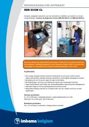
<strong>Comparator</strong><br />
single-phase or three-phase<br />
<strong>COM</strong> <strong>1003</strong> / <strong>3003</strong>
Front View<br />
Features<br />
Functions<br />
User Software<br />
®<br />
<strong>Comparator</strong> <strong>COM</strong> <strong>1003</strong> / <strong>3003</strong><br />
By continuation of previous developments the new <strong>COM</strong> <strong>1003</strong> / <strong>COM</strong> <strong>3003</strong> comparator<br />
is the new member of the ZERA high precision measuring instrument series.<br />
According to the measuring requirements 2 versions are available:<br />
Single phase instrument <strong>COM</strong> <strong>1003</strong> or three phase instrument <strong>COM</strong> <strong>3003</strong>. These comparators<br />
are common used in metrological institutes but also official test laboratories, power<br />
utilities and meters manufactures use this kind of high accurate instruments to perform their<br />
traceability to national or international standards.<br />
High accuracy, independent of measuring mode,<br />
Excellent long-term stability,<br />
Use of DC-capable current transformers ,<br />
Recalibration period by PTB (German National Metrology Laboratory) set for 2 years,<br />
RS 232 and IEEE 488 interfaces,<br />
SCPI compatible IEEE 488 interface commands,<br />
Automatic measuring range selection,<br />
Only one current input for the whole measuring range,<br />
Direct traceability of measuring accuracy by connection of DC standard and frequency<br />
standard devices.<br />
The <strong>COM</strong> <strong>1003</strong> / <strong>COM</strong> <strong>3003</strong> comparator can be controlled by :<br />
menu-related function keys and 6,4” color TFT display, located on the front panel<br />
Windows (application software SSM 3000).<br />
The following functions are<br />
selectable by softkeys:<br />
Indication of:<br />
Actual values,<br />
Vectorial diagram,<br />
Curves,<br />
Harmonics,<br />
Error measurments<br />
The SSM 3000 control program<br />
contained in the scope of supply<br />
is an MS Windows ( 95/98/<br />
NT4... application which extends<br />
the possible applications of the<br />
<strong>COM</strong><strong>1003</strong>/ <strong>COM</strong> <strong>3003</strong> with<br />
numbers of additional features. Display with menu-related function keys
The following system parameters are displayed<br />
as averages values over an adjustable<br />
integration time (1s...99s):<br />
RMS values of phase voltages and currents and<br />
their DC component,<br />
All angles between currents and voltages calculated<br />
from the fundamental components,<br />
Active, reactive and apparent power, per phase<br />
or total,<br />
Frequency and direction of rotating field.<br />
Actual vaulues can be displayed in table form or as<br />
vectorial graphic.<br />
The waveforms of voltage and currents can be measured<br />
and displayed. The user can choose between<br />
display as curves with indication of individual values<br />
and harmonic displaying with individual distortion<br />
values.<br />
Static and electromechanical power meters as well<br />
as all kind of measuring instruments with power proportional<br />
frequency output (e.g. reference standards,<br />
working standards) can be tested in the menu ‚Accuracy<br />
measurement‘. The user can select between<br />
scanning head input or frequency input.<br />
All measuring results can be stored at incorporated<br />
Compact-Flash Cards afterwards. The stored data<br />
can be processed to the PC. The device to read out<br />
the Compact-Flash Cards is contained in the scope<br />
of supply.<br />
<strong>Comparator</strong> <strong>COM</strong> <strong>1003</strong> / <strong>3003</strong><br />
®<br />
Rear View<br />
Actual Value Measurement<br />
Vectorial Measurement<br />
Curve Measurement<br />
Harmonics Measurement<br />
Accuracy Measurement
Unless otherwise indicated, all<br />
measurement errors are related<br />
to sine-wave test parameters in<br />
the nominal frequency range and<br />
appropriate range selection.<br />
Power supply<br />
Power consumption<br />
Test voltage<br />
Voltage ranges<br />
Test current<br />
Current ranges<br />
Reference voltage ranges<br />
Fundamental frequency<br />
Bandwith<br />
Measuring mode<br />
© ZERA GmbH com<strong>3003</strong>/UK/1000/06/03<br />
<strong>Comparator</strong> <strong>COM</strong> <strong>1003</strong> / <strong>3003</strong><br />
<strong>Comparator</strong> <strong>COM</strong> <strong>1003</strong> <strong>COM</strong> <strong>3003</strong><br />
Accuracy class rating according to PTB for measuring<br />
type independent of power and energy in the<br />
30 ... 500 V and 50 mA ... 160 A ranges<br />
Recalibration period according to PTB<br />
Voltage measurement error<br />
Voltage measurement drift<br />
Current measurement error<br />
Current measurement drift<br />
Power/energy measurement error<br />
(related to apparent power irrespective of measurement Type,<br />
each with 30 ... 500 V)<br />
Power/energy measurement drift<br />
Angle measurement error<br />
DC reference voltage measurement<br />
DC reference voltage measurement drift<br />
Temperature range<br />
Temperature drift<br />
Inputs / Outputs<br />
Max. Dimensions (H x W x D)<br />
Weight<br />
230 V +10% -15%, 50 ... 60 Hz<br />
approx. 80 VA<br />
30 V ... 500 V<br />
60-120-240-480 V<br />
1 mA ... 160 A<br />
5-10-20-50-100-200-500 mA<br />
1-2-5-10-20-50-100-200 A<br />
1 V and 10 V DC<br />
15 ... 70 Hz<br />
DC ... 3500 Hz<br />
2 wire Active<br />
2 wire Reactive<br />
< 100 x 10 -6<br />
2 years<br />
< 30 x 10 -6<br />
< 15 x 10 -6 / year<br />
< 50 x 10 -6 (50 mA ... 160 A)<br />
< 150 x 10 -6 (10 mA ... 50 mA)<br />
< 250 x 10 -6 (1 mA ...10 mA)<br />
< 25 x 10 -6 / year<br />
< 80 x 10 -6 (50 mA ... 160 A)<br />
< 180 x 10 -6 (10 mA ... 50 mA)<br />
< 280 x 10 -6 (1 mA ...10 mA)<br />
< 30 x 10 -6 / year<br />
< 0,005°<br />
< 20 x 10 -6<br />
< 5 x 10 -6 / year<br />
230 V +10% -15%, 50 ... 60 Hz<br />
approx. 120 VA<br />
30 V ... 500 V<br />
60-120-240-480 V<br />
1 mA ... 160 A<br />
5-10-20-50-100-200-500 mA<br />
1-2-5-10-20-50-100-200 A<br />
1 V and 10 V DC<br />
15 ... 70 Hz<br />
DC ... 3500 Hz<br />
4 wire Active<br />
4 wire Reactive true<br />
4 wire Reactive cross<br />
4 wire Reactive Q60<br />
4 wire Apparent<br />
3 wire Active<br />
3 wire Reactive true<br />
3 wire Reactive cross connected A<br />
3 wire Reactive cross connected B<br />
2 wire Active<br />
2 wire Reactive<br />
< 100 x 10 -6<br />
2 years<br />
< 30 x 10 -6<br />
< 15 x 10 -6 / year<br />
< 50 x 10 -6 (50 mA ... 160 A)<br />
< 150 x 10 -6 (10 mA ... 50 mA)<br />
< 250 x 10 -6 (1 mA ...10 mA)<br />
< 25 x 10 -6 / year<br />
< 80 x 10 -6 (50 mA ... 160 A)<br />
< 180 x 10 -6 (10 mA ... 50 mA)<br />
< 280 x 10 -6 (1 mA ...10 mA)<br />
< 30 x 10 -6 / year<br />
< 0,005°<br />
< 20 x 10 -6<br />
< 5 x 10 -6 / year<br />
15° ... 40° C<br />
U < 0,5 x 10⁻⁶ / K<br />
� < 0,5 x 10⁻⁶ / K<br />
P < 1 x 10⁻⁶ / K<br />
DC reference input < 1 x 10⁻⁶ / K<br />
Quartz time base < 0,1 x 10⁻⁶ 15° ... 40° C<br />
U < 0,5 x 10<br />
/ K<br />
1 x current<br />
1 x voltage<br />
1 x 1 V and 10 V DC reference input<br />
2 x power proportional pulse output<br />
1 x pulse input for energy comparison measurement<br />
1 x Scanning head input for meter testing<br />
1 x Quarz output for internal time base<br />
1 x RS232 interface<br />
1 x IEEE 488 interface<br />
1 x ZERA fibre optics interface<br />
172 x 465 x 460 mm<br />
16,0 Kg<br />
-6 / K<br />
� < 0,5 x 10⁻⁶ / K<br />
P < 1 x 10⁻⁶ / K<br />
DC reference input < 1 x 10⁻⁶ / K<br />
Quartz time base < 0,1 x 10⁻⁶ / K<br />
3 x current<br />
3 x voltage<br />
1 x 1 V and 10 V DC reference input<br />
2 x power proportional pulse output<br />
1 x pulse input for energy comparison measurement<br />
1 x Scanning head input for meter testing<br />
1 x Quarz output for internal time base<br />
1 x RS232 interface<br />
1 x IEEE 488 interface<br />
1 x ZERA fibre optics interface<br />
172 x 465 x 460 mm<br />
25,0 Kg<br />
®<br />
Subject to alterations<br />
Technical Data<br />
Other Products:<br />
Stationary Test Systems<br />
for Electricity Meters<br />
Portable<br />
Meter Test Equipment<br />
Stationary and Portable<br />
Power Sources<br />
Insulation Testers<br />
Test Systems for<br />
Instrument Transformers<br />
Test Systems for<br />
Circuit Breakers and<br />
Switch Gears<br />
Voltage Stabilizers<br />
Test Equipment for<br />
Ripple-Control Receiver<br />
Primary Injection Test Sets<br />
Secondary Injection Test Sets<br />
Stationary and Portable<br />
Test Systems for Calibration<br />
of Measuring Transducers<br />
Modernisation of<br />
Meter Test Systems<br />
®<br />
ZERA GmbH<br />
Hauptstraße 392<br />
D-53639 Königswinter<br />
Tel.:+49 (0)2223 704-0<br />
Fax:+49 (0)2223 704-70<br />
info@zera.de<br />
www.zera.de<br />
Commercial Register<br />
Inferior Court Siegburg<br />
HRB 7073