OPERATOR'S MANUAL - Northern Lights
OPERATOR'S MANUAL - Northern Lights
OPERATOR'S MANUAL - Northern Lights

You also want an ePaper? Increase the reach of your titles
YUMPU automatically turns print PDFs into web optimized ePapers that Google loves.
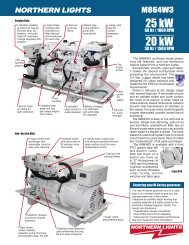
OM773LW3<br />
For Model: M773LW3<br />
OPERATOR’S <strong>MANUAL</strong><br />
Marine Generators | Marine Diesel Engines | Land-Based Generators
— CALIFORNIA —<br />
Proposition 65 Warning:<br />
Diesel engine exhaust and some of its constituents<br />
are known to the State of California to cause<br />
cancer, birth defects, and other reproductive harm.<br />
<strong>Northern</strong> <strong>Lights</strong><br />
4420 14th Avenue N.W.<br />
Seattle, WA 98107<br />
Tel: (206) 789-3880<br />
Fax: (206) 782-5455<br />
Copyright ©2012 <strong>Northern</strong> <strong>Lights</strong>, Inc.<br />
All rights reserved. <strong>Northern</strong> <strong>Lights</strong>, and<br />
the <strong>Northern</strong> <strong>Lights</strong> logo are trademarks of<br />
<strong>Northern</strong> <strong>Lights</strong>, Inc.<br />
Printed in U.S.A.<br />
PART NO.: OM773LW3 07/12
<strong>OPERATOR'S</strong> <strong>MANUAL</strong><br />
for Model<br />
M773LW₃<br />
Read this operator's manual thoroughly before starting to operate your equipment.<br />
This manual contains information you will need to run and service your new unit.<br />
Table of Contents<br />
INTRODUCTION ....................................................2<br />
Models Included .................................................2<br />
Model Numbers ..................................................2<br />
Serial Numbers ...................................................2<br />
WARRANTY ............................................................3<br />
SAFETY RULES ...............................................3 - 7<br />
LOCK OUT / TAG OUT PROCEDURES .......... 8<br />
COMPONENT LOCATIONS<br />
M773LW Marine Generators ........................... 10<br />
M773LW3 Marine Generators ..........................11<br />
PANELS<br />
<strong>Northern</strong> <strong>Lights</strong> Generator Sets ............... 12 - 13<br />
OPERATING PROCEDURES<br />
Break-in Period ................................................ 14<br />
Before Starting ................................................. 14<br />
Starting ............................................................. 14<br />
Operating ......................................................... 14<br />
Stopping ........................................................... 14<br />
Shutdowns and Alarms .................................... 15<br />
Spare Parts ....................................................... 15<br />
SERVICING SCHEDULE CHART .................... 16<br />
SERVICING RECORD NOTES ....................... 17<br />
Proprietary Information<br />
OM773LW3 07/12<br />
1<br />
SERVICING<br />
Lubrication - General ....................................... 18<br />
Checking Oil .................................................... 18<br />
Oil Changes ..................................................... 18<br />
Changing Oil Filter .......................................... 18<br />
Air Filter .......................................................... 19<br />
V-Belts ............................................................. 19<br />
Valve Clearances .............................................. 19<br />
Fuels - General ................................................. 20<br />
Fuel Filters ....................................................... 20<br />
Bleeding the Fuel System ................................ 21<br />
Injector Service ........................................ 22 - 23<br />
Injection Pump ................................................. 23<br />
Cooling System - General ................................ 23<br />
Cooling System Flushing ................................. 24<br />
Heat Exchanger ............................................... 24<br />
Raw Water Pump ............................................. 24<br />
Generator Ends ................................................ 24<br />
Electrical System - General ............................. 24<br />
Glow Plugs ....................................................... 25<br />
Booster Batteries .............................................. 25<br />
Battery Care ..................................................... 25<br />
Winterizing / Out-of-Service ........................... 25<br />
TROUBLESHOOTING<br />
Electrical .......................................................... 26<br />
Engine ...................................................... 27 - 29<br />
WIRING DIAGRAMS<br />
AC Electrical ........................................... 30 - 31<br />
DC Electrical ........................................... 32 - 39<br />
This publication is the property of <strong>Northern</strong> <strong>Lights</strong>, Inc.<br />
It may not be reproduced in whole or in part without the written permission of <strong>Northern</strong> <strong>Lights</strong>, Inc.<br />
© <strong>Northern</strong> <strong>Lights</strong>, Inc. All rights reserved. Litho U.S.A. Publication number OM773LW3 07/12
Servicing of marine engines and generator sets<br />
presents unique problems. In many cases boats<br />
cannot be moved to a repair facility. Marine engines<br />
cannot be compared to the servicing of automobiles,<br />
trucks or even farm equipment. Failures often occur<br />
in remote areas far from competent assistance.<br />
Marine engines are taxed far more severely than<br />
auto or truck engines; therefore, maintenance schedules<br />
must be adhered to more strictly.<br />
MODELS INCLUDED<br />
This manual covers the operating instructions for:<br />
M - <strong>Northern</strong> <strong>Lights</strong> marine generator set<br />
Introduction<br />
OM773LW3 07/12<br />
2<br />
Failures begin with minor problems that are overlooked<br />
and become amplifi ed when not corrected<br />
during routine maintenance.<br />
M773LW3 marine generator setModel numbers give the unit's<br />
application, block model, aspiration, and RPM:<br />
M773LW3 =<br />
M 773<br />
<strong>Northern</strong> <strong>Lights</strong> marine generator set with a<br />
773 engine, PX-309K2 generator end, AVR,<br />
Tier III.<br />
Figure 1: Generator set serial number plate.<br />
Unit Identifi cation<br />
As operator, it is your obligation to learn about your<br />
equipment and its proper maintenance. This is not a<br />
comprehensive technical service manual. Nor will it<br />
make the reader into an expert mechanic. Its aim is<br />
to aid you in maintaining your unit properly.<br />
Model numbers give the unit’s application, block model, aspiration, and RPM<br />
+<br />
Model number of engine block<br />
Bore Cylinders +<br />
77 mm 3<br />
Serial Numbers<br />
L, W, 3<br />
L - Long stroke<br />
W - New Winding in<br />
Generator End,<br />
3 - Tier III<br />
Your set has three serial numbers: 1 an engine number stamped<br />
on the block, 2 a generator plate, and 3 a generator set plate.<br />
Use the serial number on the generator set plate when ordering parts<br />
or in correspondence. The generator set plate is found on the service<br />
side of the generator and resembles the drawing in Figure 1.
A warranty registration certifi cate is supplied<br />
with your set. The extent of coverage is described<br />
in the Limited Warranty Statement. We<br />
recommend that you study the statement carefully.<br />
Warranty<br />
Safety Rules<br />
OM773LW3 07/12<br />
3<br />
NOTE: If the warranty is to apply, the servicing<br />
instructions outlined in this manual must be<br />
followed. If further information is needed, please<br />
contact an authorized dealer or the factory.<br />
NOTICE: Accident reports show that careless use of engines causes a high percentage of accidents.<br />
You can avoid accidents by observing these safety rules. Study these rules carefully and enforce them on the job.<br />
IMPORTANT SAFETY INSTRUCTIONS.<br />
Electromagnetic equipment, including generator sets<br />
and their accessories, can cause bodily harm and<br />
life threatening injuries when improperly installed,<br />
operated or maintained. To prevent accidents be aware<br />
of potential dangers and act safely.<br />
READ AND FOLLOW ALL SAFETY<br />
INSTRUCTIONS IN THIS <strong>MANUAL</strong>,<br />
PRIOR TO THE INSTALLATION<br />
OF ANY GENERATOR SET OR<br />
ACCESSORY. KEEP THESE<br />
INSTRUCTIONS FOR FUTURE<br />
REFERENCE.<br />
Recognize Safety Symbols and Instructions<br />
In addition to the information found in this section, this<br />
operator’s manual uses three different signal words to<br />
outline potential dangers of a specifi c nature.<br />
DANGER indicates a hazardous situation which, if<br />
not avoided, will result in death or serious injury.<br />
WARNING indicates a hazardous situation which, if<br />
not avoided, could result in death or serious injury.<br />
CAUTION indicates a hazardous situation which,<br />
if not avoided, could result in minor or moderate<br />
injury.<br />
updated 3-13-12<br />
Follow All Safety Instructions<br />
Carefully read and understand<br />
all safety messages in this<br />
manual and on your machine’s<br />
safety signs. Keep signs in good<br />
and clean condition. Replace<br />
missing or damaged signs. Be<br />
sure new equipment components and repair parts<br />
include the current safety signs. For replacement signs,<br />
proper placement of safety signs or clarifi cation on any<br />
safety issue, consult your <strong>Northern</strong> <strong>Lights</strong> dealer or the<br />
factory.<br />
There can be additional safety information contained<br />
on parts and components from outside suppliers<br />
that is not reproduced in this manual. Consult the<br />
suppliers for additional safety information.<br />
Learn how to operate the machine and how to use<br />
the controls properly. Only trained personnel should<br />
operate machines, or work on or around them.<br />
Keep you machine in proper working condition.<br />
UNAUTHORIZED MODIFICATIONS TO THE<br />
MACHINERY MAY IMPAIR ITS FUNCTION<br />
AND SAFETY PARAMETERS.<br />
Prevent Bypass and Accidental Starting<br />
Do not start engine by shorting<br />
across start terminal. Engine will<br />
start if normal circuitry is bypassed,<br />
creating a hazard by runaway<br />
machinery.<br />
Start engine only from operator’s station.<br />
Handle Fuel Safely - Avoid Flames<br />
Diesel is highly fl ammable and should be treated<br />
with care at all times. Do do not refuel while<br />
smoking or when near sparks or open fl ame.<br />
ALWAYS STOP ENGINE<br />
BEFORE FUELING<br />
MACHINE. Always fi ll<br />
portable fuel tank outdoors.<br />
Never fuel a hot engine.
Prevent accidental discharge of starting fl uids by<br />
storing all cans in a cool, safe place, away from sparks<br />
or open fl ame. Store with cap securely on container.<br />
Never incinerate or puncture a fuel container.<br />
Prevent fi res by keeping machine clean of accumulated<br />
trash, grease and debris. Always clean any spilled fuel<br />
as swiftly as possible. Do not store oily rags, which<br />
can ignite and burn spontaneously.<br />
Be prepared if a fi re starts. Keep a fi rst aid kit and fi re<br />
extinguisher handy. Keep emergency contact numbers<br />
for fi re department, doctors, ambulance and hospital<br />
near the telephone.<br />
Service Machines Safely<br />
Do not wear a necktie, scarf,<br />
necklace, rings or other<br />
jewelry, or any loose clothing<br />
when working near moving<br />
parts. Tie long hair behind your head. If any of these<br />
items get caught in moving machinery, severe injury or<br />
death could result.<br />
Check for any loose electrical connections or faulty<br />
wiring.<br />
Look completely around engine to make sure that<br />
everything is clear before starting.<br />
Wear Protective Clothing<br />
To prevent catching anything in moving machinery,<br />
always wear close fi tting clothes and safety equipment<br />
appropriate to the job.<br />
Prolonged exposure to loud noise can cause hearing<br />
loss or impairment.<br />
Wear suitable authorized<br />
hearing protection, such<br />
as earmuffs or plugs to<br />
protect against loud noises.<br />
Revised 3-13-12<br />
Safety Rules (Continued)<br />
OM773LW3 07/12<br />
4<br />
Operating equipment requires the full attention of<br />
the operator. Do not use radio or music headphones<br />
while operating machinery.<br />
Practice Safe Maintenance<br />
Understand all service procedures<br />
before starting work. Keep area clean and dry.<br />
Never lubricate, service, or adjust machine while it is<br />
in operation.<br />
Keep hands, feet and clothing away from powerdriven<br />
equipment. When shutting down an engine,<br />
disengage all power and operator controls. Allow<br />
the engine to cool completely before beginning any<br />
service work.<br />
Securely support any machinery elements that must<br />
be raised for service work with support or lifting<br />
machinery specifi cally intended for that purpose.<br />
Keep all parts in good conditions and properly<br />
installed. Fix damage immediately. Replace any<br />
worn or broken parts. Remove any build up of<br />
grease, oil or debris.<br />
Disconnect battery ground cable (-) before making<br />
any adjustments or service work.<br />
Stay Clear of Rotating Drivelines<br />
Entanglement in rotating drivelines can cause serious<br />
injury or death. Keep shields in place at all times.<br />
Make sure that rotating shields turn freely in pace<br />
with the drivelines.<br />
Do not wear loose fi tting equipment around rotating<br />
drivelines. Stop the engine and make sure that all<br />
moving parts have stopped<br />
before making any adjustments,<br />
connections, or performing<br />
any other type of service to<br />
the engine or other driven<br />
equipment.
Install all Safety Guards<br />
Direct contact with rotating<br />
fans, belts, pulley and drives<br />
can cause serious injury.<br />
Keep all guards in place at all<br />
times during engine operation.<br />
Wear close-fi tting clothes. Stop the engine and be<br />
sure all fans, belts, pulleys and drives are stopped<br />
before making adjustments, connections, or cleaning<br />
near fans and their components.<br />
Do not allow anything on your person to dangle into<br />
or come in contact with a moving fan, belt, pulley or<br />
drive. Fans can act as vacuums and pull materials<br />
up from below, so avoid that area as well while in<br />
service.<br />
Safe Battery Handling<br />
Prevent Battery Explosions<br />
Battery gas is highly<br />
fl ammable. Battery<br />
explosions can cause severe<br />
injury or death. To help<br />
prevent battery explosions, keep sparks, lighted<br />
matches and open fl ame away from the top of battery.<br />
When checking battery electrolyte level, use a<br />
fl ashlight.<br />
Never check battery charge by contacting the posts<br />
with a metal object. Use a volt-meter or hydrometer.<br />
Frozen batteries may explode if charged. Never<br />
charge a battery that has not been allowed to warm to<br />
at least 16 o C (60 o F).<br />
Always remove grounded (-) battery clamp fi rst and<br />
replace ground clamp last.<br />
Sulfuric acid in battery electrolyte is poisonous and<br />
strong enough to burn skin, eat holes into clothing and<br />
other materials, and cause blindness if splashed into eyes.<br />
Revised 7-9-12<br />
Safety Rules (Continued)<br />
OM773LW3 07/12<br />
5<br />
To Avoid Hazards:<br />
• Fill batteries only in well-ventilated areas.<br />
• Wear appropriate eye protection and rubber gloves.<br />
• Never use air pressure to clean batteries.<br />
• Wear appropriate ventilation equipment to avoid<br />
inhaling fumes when adding electrolyte.<br />
• Do not spill or drip electrolyte.<br />
• Use correct jump-start procedure if required.<br />
If acid is spilled on skin or in eyes:<br />
1. Flush skin with water.<br />
2. Apply baking soda or lime to<br />
help neutralize acid.<br />
3. Flush eyes with water for<br />
15-30 minutes.<br />
4. Get medical attention<br />
immediately.<br />
If acid is swallowed:<br />
1. DO NOT induce vomiting.<br />
2. Drink large amounts of<br />
water or milk, without<br />
exceeding 2 liters<br />
(2 quarts)<br />
3. Get medical attention immediately<br />
Battery posts, terminals, and related accessories<br />
can contain lead and lead compounds, chemicals<br />
known to the State of California to cause cancer and<br />
reproductive harm. Wash hands after handling.<br />
Handle Chemical Products Safely<br />
Direct exposure to hazardous<br />
chemicals can cause serious injury.<br />
Among the potentially hazardous<br />
chemicals that may be used<br />
with <strong>Northern</strong> <strong>Lights</strong><br />
products are lubricants,<br />
coolants, paints and adhesives.<br />
All potentially hazardous chemicals come with a Material<br />
Safety Data Sheet (MSDS). The MSDS provides specifi c<br />
details on chemical products, including physical hazards,<br />
safety procedures and emergency response techniques
Read and understand the MSDS for each chemical before<br />
you start any job that includes it. Follow the procedures<br />
and use appropriate equipment exactly as recommended.<br />
Contact your <strong>Northern</strong> <strong>Lights</strong> dealer or <strong>Northern</strong> <strong>Lights</strong><br />
factory for MSDS’s used on <strong>Northern</strong> <strong>Lights</strong> products.<br />
Work in Well Ventilated Areas<br />
Exhaust fumes from engines contain carbon monoxide<br />
and can cause sickness or death. Work in well ventilated<br />
areas to avoid prolonged exposure to engine fumes. If it<br />
is necessary to run an engine in an enclosed area, route<br />
the exhaust fumes out of the area with an approved, leak<br />
proof exhaust pipe extension.<br />
Remove Paint Before Welding or Heating<br />
Hazardous fumes can be generated<br />
when paint is heated by welding,<br />
soldering or using a torch. To avoid<br />
potentially toxic fumes and dust,<br />
remove paint before heating.<br />
• Remove paint a minimum of 100<br />
mm (4 in.) from the<br />
area that will be affected by heat.<br />
• If paint cannot be removed, wear an approved respirator.<br />
• If you sand or grind paint, use an approved respirator.<br />
• If you use solvent or paint stripper, remove stripper<br />
with soap and water before welding. Remove<br />
solvent or paint stripper containers from the area.<br />
• Allow at least 15 minutes for fumes to disperse<br />
before welding or heating.<br />
Do not use a chlorinated solvent in an area where welding<br />
will occur. Work only in areas that are well ventilated.<br />
Dispose of paint and solvent properly.<br />
Service Cooling System Safely<br />
Opening a pressurized cooling<br />
system can release explosive<br />
fl uids and causing serious burns.<br />
Before opening any pressurized<br />
cooling system, make sure the<br />
Revised 3-13-12<br />
Safety Rules (Continued)<br />
OM773LW3 07/12<br />
6<br />
engine has been shut off. Do not remove a fi ller cap<br />
unless it is cool enough to comfortably grip with bare<br />
hands. Slowly loosen cap to relieve pressure before<br />
opening fully.<br />
Avoid High Pressure Fluids<br />
Relieve pressure prior to<br />
disconnecting pressurized lines.<br />
Escaping fl uid under pressure<br />
can penetrate the skin causing<br />
serious injury. Always relieve pressure before<br />
disconnecting hydraulic or other pressurized lines.<br />
Tighten all connections fi rmly before re-applying<br />
pressure.<br />
If searching for leaks, use a piece of cardboard.<br />
Always protect your hands and other body parts from<br />
high-pressure fl uids.<br />
If an accident occurs, see a doctor immediately. Any<br />
high pressure spray injected into the skin must be<br />
removed within a few hours to prevent the risk of<br />
gangrene or other infection.<br />
Avoid Heating Near Pressurized Fluid Lines<br />
Flammable spray can be generated<br />
by heating near pressurized fl uid<br />
lines, resulting in severe burns and<br />
bodily injury. Pressurized lines<br />
can rupture when heat goes beyond the immediate<br />
fl ame area. Do not weld, solder or use a torch or<br />
open fl ame near pressurized lines or other fl ammable<br />
fl uids.<br />
Do Not Open High-Pressure Fuel System<br />
Many <strong>Northern</strong> <strong>Lights</strong> engines use high-pressure<br />
fuel injection. High-pressure fl uid remaining in fuel<br />
lines can cause serious injury. Do not disconnect or<br />
attempt any repair of fuel lines, sensors, or other
components between the high-pressure fuel pump<br />
and nozzles on engines with high pressure fuel<br />
systems.<br />
ONLY AUTHORIZED TECHNICIANS<br />
CAN PERFORM REPAIRS ON AN HIGH<br />
PRESSURE FUEL INJECTION SYSTEMS.<br />
Avoid Hot Exhaust<br />
Avoid exposure to and physical<br />
contact with hot exhaust<br />
gases. Exhaust parts and streams can reach high<br />
temperatures during operation, leading to burns or<br />
other serious injury.<br />
Cleaning exhaust fi lters can also lead to exposure to<br />
hot exhaust gas and the injury risk associated with<br />
it. Avoid exposure to and physical contact with hot<br />
exhaust gases when cleaning exhaust fi lters.<br />
During auto or manual/stationary exhaust fi lter<br />
cleaning operations, the engine will run at<br />
elevated temperatures for an extended period of<br />
time. Exhaust parts and streams can reach high<br />
temperatures during operation, leading to burns or<br />
other serious injury.<br />
Avoid Harmful Asbestos Dust<br />
Inhaling asbestos fi bers may cause<br />
lung cancer. Avoid breathing any<br />
dust that may be generated when<br />
handling components containing<br />
asbestos fi bers, including some<br />
gaskets.<br />
The asbestos used in these components is usually<br />
found in a resin or otherwise sealed. Normal<br />
handling of these components is not dangerous,<br />
as long as airborne dust containing asbestos is not<br />
generated.<br />
Avoid creating dust. Never use compressed air for<br />
cleaning. Avoid brushing or grinding materials<br />
containing asbestos. When servicing, wear an<br />
approved respirator. A special vacuum cleaner is<br />
recommended to clean asbestos. If this vacuum is<br />
not available, apply a mist of oil or water on the<br />
Revised 3-13-12<br />
Safety Rules (Continued)<br />
OM773LW3 07/12<br />
7<br />
material containing asbestos. Keep all bystanders<br />
away from any area where asbestos dust may be<br />
generated.<br />
Use Proper Lifting Equipment and Techniques<br />
Lifting heavy components incorrectly<br />
can cause severe injury or damage<br />
to machinery. Avoid unbalanced<br />
loads. Do not use lifting eyes. Lift the<br />
generator set using lifting bars inserted<br />
through the lifting holes on the skid.<br />
Follow all recommended removal and installation<br />
procedures in this and associated <strong>Northern</strong> <strong>Lights</strong><br />
manuals.<br />
Use Proper Tools<br />
Makeshift tools and procedures<br />
can create safety hazards.<br />
Always use appropriate tools for<br />
the job.<br />
Use power tools only to loosen threaded parts and<br />
fasteners. For loosening and tightening hardware,<br />
always use the correct sized tools.<br />
Do not use US measurement tools on metric<br />
fasteners, or vice versa. Use only service parts that<br />
meet <strong>Northern</strong> <strong>Lights</strong> specifi cations.<br />
Dispose of Waste Properly<br />
Disposing of waste improperly can threaten the<br />
environment and lead to unsafe working conditions.<br />
Potentially harmful waste used in <strong>Northern</strong> <strong>Lights</strong><br />
equipment can include oil, fuel, coolant, fi lters and<br />
batteries.<br />
Use leakproof containers to drain fl uid. Do not<br />
use food or beverage containers that may mislead<br />
someone into drinking from them.<br />
Do not pour waste onto the ground, down a drain or<br />
into any water source.
General Policy<br />
To avoid dangerous or hazardous situations, refrain from<br />
any of the following:<br />
• Removing or bypassing a guard or other safety device<br />
• Placing any part of your body in a position where you<br />
could be caught by moving machinery.<br />
• Cleaning or oiling machinery when in operation.<br />
• Adjusting circuits, chillers, pumps, air handlers, valves,<br />
circuit breakers or fans while in operation.<br />
• Working on piping or high pressure systems.<br />
Lock Out/Tag Out Instructions -<br />
Electrical Equipment<br />
Be sure the equipment’s ON/OFF switch is in the OFF<br />
position and is unplugged from any electrical source before<br />
attempting to perform any type of work on the equipment.<br />
Obtain an electrical plug cap cover with a lockset. Secure<br />
the plug terminal end using the electrical plug lockout cap.<br />
Lock the cap and retain the key.<br />
If the equipment is directly wired into an electrical box with<br />
a shut off switch, obtain a lock pad and/or the appropriate<br />
colored tags and place the lock and tag through the shut<br />
off lever. Retain the key until the repair is completed and<br />
the machine is safe to start. Be certain the shut off lever<br />
is in the OFF position before restarting. NEVER give a<br />
lock out key to unauthorized personnel.<br />
If the equipment is directly wired into an electrical box<br />
without a shut off switch and lock out capability, then a<br />
circuit breaker lock out will be required. Obtain a circuit<br />
lock and tag set. Install the lock onto the circuit breaker<br />
box. Ensure the unit ON/OFF switch is in the OFF position<br />
before restarting.<br />
Lock Out/Tag Out Instructions -<br />
Pneumatic and Hydraulic Equipment<br />
For servicing pneumatic and hydraulic equipment, the<br />
following additional procedures must be implemented,<br />
following completion of lock out/tag out procedures for<br />
the unit to be serviced:<br />
Shut off air, water or supply valves at the equipment to<br />
be serviced.<br />
Check the local bleed-off point for completed release of<br />
pressurized air, water or oil.<br />
Added 2-24-12<br />
Lock Out / Tag Out Procedures<br />
Scope<br />
During maintenance, repairs or retooling of a <strong>Northern</strong> <strong>Lights</strong> generator set, simply turning the machine off or unplugging<br />
it while it is being worked on does not give enough protection to others who are not performing the maintenance or<br />
repair. Many serious accidents happen when someone thought the machine was turned off, or all of its energy was<br />
safely blocked or released.<br />
OM773LW3 07/12<br />
8<br />
If shutting off of air, water or other material cannot be<br />
achieved at the local supply valve, shut off valves further<br />
back in the system and re-check the bleed-off point until<br />
complete shut-off is achieved.<br />
Affi x a DO NOT OPERATE tag to each valve handle that<br />
requires shut off. Each DO NOT OPERATE tag must be<br />
signed and dated by the authorized technician servicing<br />
the equipment.<br />
Lock Out/Tag Out Instructions -<br />
Air Hose Connected Pneumatic Equipment<br />
Equipment connected to the compressed air system<br />
through an air hose with a detachable fi tting must be<br />
shutdown and unplugged. Excess air must be bled prior<br />
to removing the air hose, prior to any maintenance or<br />
repair activities.<br />
Affi x a DO NOT OPERATE tag to the air hose near the<br />
detachable fi tting. Each DO NOT OPERATE tag must be<br />
signed and dated by the authorized technician servicing<br />
the equipment. Check that the equipment cannot be<br />
operated by activating the ON switch.<br />
Stored Energy<br />
Immediately after applying Lock Out or Tag Out devices,<br />
ensure that all potentially hazardous stored or residual<br />
energy is relieved, disconnected, restrained and otherwise<br />
rendered safe.<br />
Verifi cation of Isolation<br />
Verify the machinery or equipment is actually isolated and<br />
de-energized prior to beginning work on a machine or on<br />
equipment that has been locked out.<br />
Restarting Procedures<br />
Follow the procedures below prior to restoring energy:<br />
• Ensure that all machinery or equipment is properly<br />
reassembled. Inspect the machinery or equipment to<br />
verify non-essential items have been removed.<br />
• Ensure that all personnel are safely outside danger<br />
zones. Notify personnel that lock out/tag out devices have<br />
been removed and energy will be reapplied.<br />
• Only authorized personnel may remove lock out/tag out<br />
devices or notices.
Notes<br />
OM773LW3 07/12<br />
9
Figure 1 & 2: M773LW with PX-309K2 generator<br />
1. Generator Control Box<br />
2. Air Filter<br />
3. Fuel Filter<br />
4. Fuel Lift Pump<br />
5. Crankcase Vent<br />
6. Lube Oil Fill, Top<br />
7. Coolant Fill<br />
8. Fuel Injector<br />
9. Stop Solenoid<br />
10. Injection Pump<br />
11. Lube Oil Fill, Side<br />
12. Seawater Pump<br />
13. Lube Oil Drain<br />
14. Base frame<br />
Marine Generator Component Locations<br />
15. Block Drain<br />
16. Fuel Inlet and Return<br />
17. Oil Dipstick<br />
18. Lube Oil Filter<br />
19. Control Panel Plug<br />
20. Generator Data Plate<br />
OM773LW3 07/12<br />
10<br />
21. AC Circuit Breaker for<br />
AVR<br />
22. DC Circuit Breaker<br />
23. Expansion Tank<br />
24. Wet Exhaust Elbow<br />
25. Vibration Mount<br />
26. Starter<br />
27. Alternator<br />
28. Heat Exchanger End<br />
Cap<br />
29. Coolant Recovery<br />
Tank
1. Generator Control Box<br />
2. DC Circuit Breaker<br />
3. Coolant Recovery<br />
Tank<br />
4. Air Filter<br />
5. Fuel Filter<br />
6. Fuel Lift Pump<br />
Marine Generator Component Locations<br />
1 2 3 4 5<br />
Figure 3 & 4: M773LW3 with PX-309K2<br />
generator end.<br />
7. Fuel Injector<br />
8. Coolant Fill<br />
9. Lube Oil Fill, Top<br />
10. Stop Solenoid<br />
11. Injection Pump<br />
12. Lube Oil Fill, Side<br />
6 7<br />
18 17<br />
16<br />
15<br />
Updated 9-16-10<br />
8 9<br />
14<br />
19 20 21 4<br />
13. Seawater Pump<br />
14. Fuel Inlet and Return<br />
15. Oil Dipstick<br />
16. Lube Oil Filter<br />
17. Oil Drain<br />
18. Generator Data Plate<br />
19. Expansion Tank<br />
OM773LW3 07/12<br />
11<br />
10<br />
24 23<br />
11<br />
12<br />
13<br />
22<br />
20. Heat Exchanger End<br />
Cap<br />
21. Wet Exhaust Elbow<br />
22. Vibration Mount<br />
23. Starter<br />
24. Alternator
Figure 5: Series 1-B Generator Control Panel<br />
Figure 6-a: Series 3 Generator Control Panel<br />
Figure 6-b: Series 4 Generator Control Panel<br />
Control Panels<br />
OM773LW3 07/12<br />
12<br />
1. SHUTDOWN BYPASS-PREHEAT SWITCH<br />
There are two functions built into this switch:<br />
1. Preheats the fuel before beginning the starting<br />
process. Press switch 10-20 seconds before<br />
attempting start-up.<br />
2. Bypasses the safety shutdown feature during<br />
starting process. Keep switch engaged while starting<br />
engine and for 2 to 3 seconds afterwards, allowing oil<br />
pressure to build beyond shutdown set point.<br />
2. ENGINE CONTROL SWITCH<br />
To start the engine, hold this switch in the START<br />
position until the engine is running.<br />
NOTE: Excessive cranking of marine sets equipped<br />
with water lift muffl er systems can cause engine<br />
damage. See page 8.<br />
After the engine starts, release the switch and it will<br />
return to RUN position. To stop the engine, hold the<br />
switch in the STOP position.<br />
NOTE: The rocker switch is used on Series 1 panels<br />
only, and has a light that glows when the set is running.<br />
3. HOUR METER<br />
Keeps track of engine running time.<br />
4. OIL PRESSURE GAUGE<br />
Shows the oil pressure in the engine lubricating system.<br />
5. WATER TEMPERATURE GAUGE<br />
Registers the temperature of the cooling water.<br />
6. D.C. VOLTMETER OR AMMETER<br />
When the engine is stopped, the voltmeter indicates the<br />
condition of the battery. When the engine is running,<br />
the voltmeter indicates the voltage output of the<br />
alternator.<br />
For Series 4 Control Panels Only:<br />
7. A.C. VOLTMETER<br />
Shows the generator output voltage.<br />
8. FREQUENCY METER (Hertz)<br />
The frequency meter indicates engine speed: 1200 or<br />
1800 RPM (60 Hz), or 1500 RPM (50 Hz).<br />
9. AMMETER SELECTOR SWITCH<br />
Used to check each phase for load condition.<br />
NOTE: Always leave this switch in the ON position<br />
while the unit is running.<br />
10. A.C. AMMETER<br />
Shows the generator load on each phase. The phase is<br />
selected with the Ammeter Selector switch (Item 9).
FIGURE 7-A: Series 7.0 through Series 7.6 Generator<br />
Control Panels.<br />
FIGURE 7-B: Status Indicators for Series 7.0 through<br />
Series 7.6 Generator Control Panels.<br />
Control Panels<br />
OM773LW3 07/12<br />
13<br />
1. SHUTDOWN BYPASS SWITCH<br />
Manual Start Panels<br />
(S-7.1 and S-7.3)<br />
Hold the switch in the START position until the<br />
engine is running.<br />
NOTE: Excessive cranking may cause engine damage.<br />
After the engine starts, release the switch and it will<br />
return to the RUN position. To stop the engine, hold<br />
the switch in the STOP position.<br />
Auto Start Panels<br />
(S-7.0, S-7.2, S-7.4, S-7.5, and S-7.6)<br />
When the switch is placed in the AUTO START<br />
position, the unit will automatically start when there is<br />
a drop in utility power.<br />
2. OIL PRESSURE GAUGE<br />
Shows the oil pressure in the engine lubricating system.<br />
3. HOUR METER<br />
Keeps track of engine running time.<br />
4. ENGINE TEMPERATURE GAUGE<br />
Registers the temperature of the coolant.<br />
5. D.C. VOLTMETER<br />
When the engine is running, the voltmeter indicates the<br />
voltage output of the alternator.<br />
6. STATUS INDICATOR PANEL<br />
Engine monitoring alarms and lamps for monitoring<br />
engine functions.<br />
7. ALARM LAMP TEST AND RESET BUTTON<br />
Press UP to test the indicator lights and press DOWN<br />
to reset the alarm.<br />
8. A.C. VOLTAGE ADJUSTMENT RHEOSTAT<br />
Voltage has been set at the factory and should only be<br />
adjusted by factory-trained personnel.<br />
9. AMMETER SELECTOR SWITCH<br />
Used to check each phase for load condition.<br />
NOTE: Always leave this switch in the ON position<br />
while the unit is running.<br />
10. FREQUENCY METER (HERTZ)<br />
The frequency meter indicates alternator current<br />
frequency: 60 Hz (1200 or 1800 RPM), or 50 Hz (1500<br />
RPM).<br />
11. A.C. VOLTMETER<br />
Shows the generator output voltage.<br />
12. A.C. AMMETER<br />
Shows the generator load on each phase. The phase is<br />
selected with the Ammeter Selector switch.
BREAK-IN PERIOD<br />
1. The fi rst 100 hours on a new or reconditioned<br />
engine are critical to its life and performance.<br />
2. Constantly check the engine temperature and oil<br />
pressure gauges (sets with Series 3 or 4 panels).<br />
3. Oil consumption is greater during break-in as<br />
piston rings take time to seat.<br />
4. Break-In Oil Changes: Change engine oil and<br />
fi lter at 50 hours. Change oil and fi lter again at<br />
100 hours, then at every 250 hours (consult<br />
Lubricants section for oil recommendation).<br />
Operating Instructions:<br />
Maintain at least a 75% load on your generator<br />
set for the fi rst 100 hours. If this is not possible,<br />
maintain no less than a 50% load to ensure proper<br />
seating of the piston rings. Vary the load to help<br />
seat the rings.<br />
BEFORE STARTING<br />
1. Check the water level by removing the pressure<br />
cap from the expansion tank. In order to give the<br />
cooling water an opportunity to expand, the level<br />
should be about 1 in. (2.5 cm) below the fi ller cap<br />
sealing surface when the engine is cold.<br />
CAUTION: Use protective clothing and open<br />
the fi ller cap carefully when the engine is<br />
warm to prevent burns.<br />
2. Check the oil level in the crankcase with the dipstick.<br />
The oil level must be in the waffl ed area between<br />
maximum and minimum level on the stick. Never<br />
allow the level to go below this area. Always add the<br />
same viscosity of oil as is already in the crankcase.<br />
3. Check the fuel tank level and open any fuel valves.<br />
4. Close the sea-cock, check and clean the sea strainer<br />
and reopen the sea-cock.<br />
5. Place the battery switch in the ON position.<br />
6. NOTE: The battery switch must always be kept<br />
ON while the engine is running. If the switch is<br />
turned OFF while the engine is running, the battery<br />
charging regulator could be ruined.<br />
Operating Procedures<br />
STARTING<br />
OM773LW3 07/12<br />
14<br />
1. Hold the Shutdown Bypass-Preheat switch in the<br />
ON position for 10 to 20 seconds before starting a<br />
cold engine. Holding the switch too long can burn<br />
out the glow plugs. This step is not necessary if the<br />
engine is already warm.<br />
2. While holding the Shutdown Bypass-Preheat switch<br />
in the ON position, push the Engine Control switch<br />
to the START position.<br />
3. As soon as the engine starts, release both switches. Do<br />
not crank the starter for more than 10 seconds<br />
consecutively. If the engine fails to start with the fi rst<br />
attempt, be sure that it has stopped completely for at<br />
least 30 seconds before re-engaging.<br />
6. NOTE: Excessive cranking of the starter on Marine<br />
sets equipped with a water lift muffl er can cause<br />
engine damage. If the engine does not start after<br />
three 10-second cranks, remove the impeller from the<br />
raw water pump. This will prevent the muffl er from<br />
fi lling with water and backfi lling the exhaust line and<br />
engine. Once the engine starts, shut it off<br />
immediately and re-install the impeller. Re-start the<br />
engine and check the exhaust overboard outlet for<br />
gushes of water.<br />
OPERATING<br />
1. Units with Series 3 and Series 4 Control Panels:<br />
check gauges often. Oil pressure must be above 15<br />
PSI. The D.C. voltmeter should read between 11 and<br />
15 volts at 80°F (25°C) ambient temperature. The<br />
coolant temperature gauge must be between167°F<br />
and 194°F (75°C to 90°C). Check the A.C. voltage<br />
and frequency meters (Series 4 panel). If the gauges<br />
deviate from normal levels, shut down the generator<br />
set and investigate.<br />
2. Let the unit run unloaded for a three to fi ve minute<br />
warm-up period.<br />
3. Add electrical load.<br />
STOPPING<br />
1. Remove electrical load from the generator set.<br />
2. Move the Engine Control switch to the STOP<br />
position momentarily.<br />
3. Shut off the seacock, fuel valve, and battery switch.
SHUTDOWNS AND ALARMS<br />
1. Generator sets have shutdown systems to stop the<br />
engine in the event of high water temperature or low<br />
oil pressure.<br />
a. Other alarms and shutdowns are available as<br />
optional equipment.<br />
NOTE: Do not rely on your shutdown to the<br />
exclusion of careful gauge monitoring. Watching<br />
your gauges can prevent damage to the unit and<br />
dangerous power losses.<br />
2. Do the following when your warning or shutdown<br />
system is activated:<br />
a. Engage the preheat switch to check the<br />
temperature gauge.<br />
b. If above 205°F (96°C), Use the Trouble Shoot<br />
ing Guide on page 22 to isolate the cause of the<br />
overheat.<br />
CAUTION: Do not remove the water fi ll<br />
cap of an overheated engine. Escaping high<br />
temperature steam can cause severe burns.<br />
Allow the engine to cool and then remove the<br />
cap slowly using protective clothing.<br />
c. Make repairs. Restart your generator set after the<br />
temperature gauge registers below 200°F (94°C).<br />
d. Watch the temperature gauge regularly and<br />
turn off the unit if the temperature rises above<br />
205°F (96°C) on Marine units. Repeat trouble-<br />
shooting.<br />
3. If shutdown is activated and the temperature gauge<br />
shows temperature within normal temperature<br />
range:<br />
a. This shutdown could have happened because of<br />
a too high exhaust temperature. This could have<br />
been caused by a damaged impeller or a partially<br />
blocked sea water strainer. Check the sea water<br />
strainer fi rst. If it is clear, then check the<br />
condition of the sea water pump impeller.<br />
b. Check the engine crankcase oil level.<br />
c. If the oil level is low, fi ll with recommended<br />
lubricating oil and restart. Watch the oil pressure<br />
gauge carefully and shut off the engine if it does<br />
not show a normal reading (20-60 PSI) after a<br />
few seconds of operation.<br />
d. If the oil level is normal, DO NOT restart the<br />
engine. Call your dealer for assistance.<br />
updated page 8-27-09<br />
Operating Procedures<br />
OM773LW3 07/12<br />
15<br />
SPARE PARTS<br />
1. <strong>Northern</strong> <strong>Lights</strong> recommends that you keep the<br />
following spare parts on hand for fi eld service. The<br />
parts are available from your local <strong>Northern</strong> <strong>Lights</strong><br />
dealer. Marine models have optional “On-Board-<br />
Kits,” a handy box that contains the most common<br />
parts you will need.<br />
2. All owners should have the following:<br />
a. Primary and secondary fuel fi lter elements<br />
b. Oil fi lters<br />
c. Air fi lter<br />
d. Alternator belt<br />
e. Thermostat and gaskets<br />
f. Seawater pump impeller & gaskets<br />
g. Glow plug<br />
h. Injector and washer<br />
3. If your set is operating a long distance from a<br />
servicing dealer, add the following:<br />
a. Complete set of injectors<br />
b. Copper washers for injector change<br />
c. Complete set of glow plugs<br />
d. Fuel lift pump
The Servicing Schedule Chart below shows the service schedule required for proper maintenance of your generator<br />
set. More detailed coverage of each Service Point (SP) is listed on the page noted in the ‘page’ column.<br />
DAILY:<br />
SP1 Check oil level in engine<br />
SP5 Check V-belt tension<br />
SP7 Check primary fuel fi lter<br />
SP13 Check coolant level<br />
Check sea strainer<br />
SP18 Check electrolyte in batteries<br />
AFTER FIRST 50 HOURS:<br />
SP2/3 Change engine oil and fi lter<br />
SP6 Adjust valves<br />
AFTER FIRST 100 HOURS:<br />
SP2/3 Change engine oil and fi lter<br />
EVERY 250 HOURS:<br />
SP2/3 Change engine oil and fi lter<br />
SP4 Check air cleaner<br />
SP19 Check state of charge of batteries<br />
Servicing Schedule Chart<br />
SERVICE 50 250 500 1000 2500<br />
POINT PAGE OPERATION DAILY Hours Hours Hours Hours Hours<br />
SP1<br />
SP2<br />
SP3<br />
SP4<br />
SP5<br />
SP6<br />
10 & 14<br />
14<br />
14<br />
15<br />
15<br />
15<br />
ENGINE:<br />
Check oil level<br />
Change engine oil 1) 5)<br />
Change lube oil fi lters 1) 5)<br />
Check air cleaner, change element @ 1000 hrs. 1) 4) 5<br />
Check V-belt tension<br />
Check valve clearances 1) 2)<br />
•<br />
•<br />
•<br />
•<br />
•<br />
•�<br />
•� �<br />
•<br />
SP7<br />
SP8<br />
SP9<br />
16<br />
16<br />
16<br />
FUEL SYSTEM:<br />
Check primary fi lter (Racor)<br />
Change primary fi lter element (Racor)<br />
Change secondary fuel fi lter<br />
2) 3)<br />
2) 3)<br />
1) 3)<br />
•<br />
•<br />
•<br />
SP10 17 Bleed the fuel system 3)<br />
SP11 19 Check injectors 1) 3) 6) 7) •<br />
SP12 19 Check fuel injection pump 7) •<br />
SP13 10 & 19<br />
SP14 20<br />
SP15 20<br />
SP17 20<br />
SP21<br />
COOLING SYSTEM:<br />
Check coolant level<br />
Check and fl ush cooling system<br />
Check and clean heat exchanger<br />
Change impeller in raw water pump<br />
Inspect condition of exhaust elbow<br />
1) 3)<br />
1) 3)<br />
•<br />
�<br />
•<br />
•<br />
•<br />
•<br />
SP18<br />
SP19<br />
21<br />
21<br />
ELECTRICAL SYSTEM:<br />
Check electrolyte level in batteries<br />
Check condition of batteries with hydrometer<br />
OUT OF SERVICE:<br />
1) 4)<br />
•<br />
•<br />
SP20 21 Winterizing or out-of-service 3)<br />
1) Perform all maintenance once a year even if hour level has not been reached.<br />
2) Consult manufacturer's maintenance schedule, note on chart.<br />
3) Whenever necessary.<br />
4) More often if necessary.<br />
5) After fi rst 50 hours, then at 100 hrs., then every 250 hrs.<br />
OM773LW3 07/12<br />
16<br />
EVERY 500 HOURS:<br />
SP8 Change primary fuel fi lter element<br />
SP9 Change secondary fuel fi lter<br />
SP21 Inspect condition of exhaust elbow<br />
EVERY 1000 HOURS:<br />
SP4 Replace air cleaner element<br />
SP6 Check valve clearances<br />
SP11 Check injectors<br />
SP17 Change impeller<br />
EVERY 2500 HOURS:<br />
SP12 Check fuel injection pump<br />
SP14 Check and fl ush cooling system<br />
SP15 Check and clean heat exchanger<br />
6) Clean injection nozzles every 1500 hours.<br />
7) For EPA emission standards fuel nozzle needs to be<br />
cleaned every 1500 hours, the fuel nozzle and fuel pump<br />
need to be cleaned, adjusted, or repaired every 3000<br />
hours, and the quality guarantee for these parts is 1500<br />
hours or 2 years.
Service Record Notes<br />
OM773LW3 07/12<br />
17
LUBRICATION - GENERAL<br />
1. Use only clean, high quality lubricants stored in<br />
clean containers in a protected area.<br />
2. These lubricants are acceptable:<br />
a. API Service CC/CD/CE single viscosity oils.<br />
b. API Service CC/CD/SF multi-viscosity oils.<br />
3. Use the proper weight oil for your average operation<br />
temperature.<br />
Air Single Multi-<br />
Temperature Viscosity Viscosity<br />
Above 32°F<br />
(0°C)<br />
-10 to 32°F<br />
(-23 to 0°C)<br />
Below -10°F<br />
(-23°C)<br />
Figure 8: Lube Oils<br />
4. Some increase in oil consumption may be expected<br />
when SAE 5W and SAE 5-20W oils are used. Check<br />
oil level frequently.<br />
5. Never put additives or fl ushing oil in crankcase.<br />
SP1. CHECKING OIL LEVEL<br />
SAE 30W SAE 15-40W<br />
SAE 10W SAE 10-30W<br />
SAE 5W SAE 5-20W<br />
1. Check the oil level in the crankcase with the dipstick.<br />
The oil level must be in the waffl ed area<br />
on the stick. Never allow the level to go below this<br />
area. Follow the lubrication recommendations above.<br />
Servicing<br />
OM773LW3 07/12<br />
18<br />
SP2. OIL CHANGES<br />
1. The set is delivered with special break-in oil.<br />
Change the engine oil and oil fi lter after 50 hours<br />
of operation. Use Service CC 30 weight oil during<br />
the fi rst 100 hours.<br />
2. Change the oil and fi lter again at 100 hours using the<br />
oil recommended in Figure 8. After this, change oil<br />
and fi lter every 250 hours.<br />
3. During intermittent cold weather operation, change<br />
oil every 100 hours or six weeks, whichever comes<br />
fi rst.<br />
4. Change oil at any seasonal change in temperature<br />
when a new viscosity of oil is required.<br />
5. Change oil when engine is warm.<br />
6. Dispose of waste oil in an approved manner.<br />
7. Never use a fl ushing oil.<br />
8. Loosen the clamp on the oil change tube. Remove<br />
cap. Drain oil. Replace the cap and tube.<br />
9. Refi ll engine with recommended oil.<br />
10. Engine capacity with new oil fi lter is:<br />
773LW3 - 4.75 quarts (4.9 liters)<br />
SP3. CHANGING LUBE OIL FILTER<br />
1. Change the lube oil fi lter every 250 hours.<br />
2. Use a fi lter wrench to remove old fi lter. Dispose of<br />
fi lter in approved manner.<br />
3. Make sure the gasket from the old fi lter is removed<br />
and discarded. Clean mount face.<br />
4. Spread a thin fi lm of engine oil on the rubber gasket<br />
on the new fi lter and screw it on nipple until gasket<br />
meets the sealing surface.<br />
5. Using hands only – no wrench – tighten fi lter<br />
one-half turn farther. Overtightening can do<br />
damage to fi lter housing.<br />
6. Fill engine with recommended oil. Start engine and<br />
check for leakage. Stop engine, wait 3 minutes, and<br />
check oil level. Add additional oil if necessary.<br />
7. Oil fi lter part numbers are:<br />
773LW3 - #24-02001
SP4. AIR CLEANER<br />
1. Inspect air cleaner every 250 hours. In dusty conditions,<br />
check more often.<br />
2. If dirty, wash element in soapy water. Rinse and dry<br />
thoroughly before re-installing.<br />
Replace if necessary. Part numbers are:<br />
M773LW3 – #24-28602<br />
3. NOTE: Make absolutely sure no impurities enter<br />
the engine while changing the element. Do NOT<br />
run the engine with the air cleaner removed.<br />
SP5. V-BELTS<br />
1. Check the tension and wear on the V-belt daily.<br />
2. Use your thumb to press on the belt at the midpoint<br />
between the crankshaft and alternator pulleys. The<br />
tension is correct if the belt can be depressed about<br />
3/16 in. (5 mm).<br />
Figure 9: Valve Adjustment<br />
Cylinder No. 1 2 3<br />
Valve Arrangement Int. Exh. Int. Exh. Int. Exh.<br />
When No.1 cylinder<br />
is at Top Dead Center<br />
in the compression<br />
stroke<br />
With the crankshaft<br />
turned 360 0 in<br />
normal direction from<br />
above<br />
Valve Arrangement<br />
Servicing<br />
OM773LW3 07/12<br />
19<br />
SP6. VALVE CLEARANCES<br />
1. Adjust valve clearance after 1000 hours or as<br />
needed.<br />
2. Valve adjustments should be done after the cylinder<br />
head bolts have been re-tightened. Engine should be<br />
cold and NOT running.<br />
3. To bring the No. 1 cylinder to top dead center in the<br />
compression stroke, align the timing mark; the top<br />
mark of the crank pulley with that of the timing gear<br />
case. Remove the rocker arm cover and turn the<br />
crankshaft foward and backward. If the inlet and<br />
exhaust valves of the No. 1 cylinder do not move<br />
it is in top dead center position. When the valves<br />
move, or rock, turn the crankshaft one full turn and<br />
align the top mark of the crank pulley with the top<br />
mark of the timing gear case.<br />
4. Loosen the lock nut and adjust the clearance between<br />
the rocker arm and valve guide of both the intake<br />
and exhaust valves with the adjustment screw (Figure<br />
9). Clearance on both intake and exhaust valves<br />
should be 0.008 in. (0.2 mm).<br />
5. Repeat steps 3 and 4 for each cylinder. Each set of<br />
valves must be adjusted individually.<br />
6. Replace the rocker arm cover. Tighten cover nuts to<br />
5 - 8 ft/lbs (0.8 - 2.3 kg/m).<br />
Figure 10: Timing Mark
FUELS - GENERAL<br />
1. Use only clean, high quality fuels of the following<br />
specifi cations, as defi ned by ASTM designation<br />
D975 for diesel fuels:<br />
a. Use grade no. 2 diesel at ambient temperatures<br />
above freezing 32°F (0°C).<br />
b. Use grade no. 1 at ambient temperatures below<br />
freezing and for all temperatures at an altitude of<br />
above 5,500 ft. (1500 meters).<br />
2. Use fuel having less that 1% sulphur (preferably less<br />
that 0.5%).<br />
3. The cetane number should be a minimum of 45.<br />
4. DO NOT use these unsuitable grades of fuel:<br />
a. Domestic heating oils, all types.<br />
b. Class B engine.<br />
c. Class D domestic fuels.<br />
d. Class E, F, G or H industrial or marine fuels.<br />
e. ASTM-D975-60T No. 4-D and higher number<br />
fuels.<br />
5. Storing fuel:<br />
a. Keep dirt, scale, water, and other foreign matter<br />
out of fuel.<br />
b. Avoid storing fuel for long periods of time.<br />
c. Fill the fuel tank at the end of each day’s<br />
operation. This will reduce condensation.<br />
Servicing<br />
OM773LW3 07/12<br />
20<br />
SP7-9. FUEL FILTERS<br />
1. Your generator set should have a primary fuel fi lter<br />
installed. We recommend the Racor brand of fuel<br />
fi lter-water separators.<br />
a. Check the primary fuel fi lter daily as<br />
recommended by the fi lter manufacturer.<br />
Empty the collection bowl as necessary.<br />
b. Change the element as often as necessary or<br />
every 500 hours.<br />
c. If the bowl fi lls with water, change the primary<br />
and secondary element immediately.<br />
2. Change secondary fuel fi lter every 500 hours or as<br />
necessary.<br />
a. Remove the spin-on fi lter by turning it<br />
counterclockwise with a fi lter wrench. Fill the<br />
new cartridge with fuel and install it after<br />
applying engine oil to gasket surface. Screw on<br />
until the gasket surface comes into contact with<br />
sealing surface of fi lter base. Then, tighten it<br />
two-thirds of a turn by hand. Do not overtighten.<br />
b. Fuel fi lter part number is:<br />
773LW3: #24-52020
SP10. BLEEDING THE FUEL SYSTEM<br />
Servicing<br />
CAUTION: Escaping diesel fuel under pressure can penetrate skin causing serious personal injury.<br />
Before disconnecting lines be sure to relieve all pressure. Before applying pressure, be sure all connections<br />
are tight and lines, pipes and hoses aren't damaged. Fuel escaping from a very small hole can be almost<br />
invisible. Use a piece of cardboard or wood, rather than hands, to search for suspected leaks. If injured by<br />
escaping fuel, see a doctor at once. Serious infection or reaction can develop if proper medical treatment<br />
isn't administered immediately.<br />
Figure 11: Fuel System.<br />
1. The fuel system is self-bleeding. However, any<br />
system may need manual bleeding when:<br />
a. A new fuel fi lter is installed;<br />
b. The engine has run out of fuel;<br />
c. The fuel lines, injection pump or any other fuel<br />
system component has been removed and<br />
installed.<br />
2. Loosen bleed bolt “A” (Figure 11) on top of the<br />
fi lter. Pump hand primer “B” on fuel lift pump until<br />
pure fuel (no bubbles) escapes from bleed bolt “A”.<br />
Tighten bleed screw “A”.<br />
OM773LW3 07/12<br />
21<br />
3. Loosen bleed screw “C”. Pump hand primer “B”<br />
until pure fuel (no bubbles) escapes. Then tighten<br />
bleed screw “C”.<br />
4. If the engine does not start after the above bleeding<br />
process, loosen a fuel line at the injector while<br />
cranking the engine with the starter motor until pure<br />
fuel escapes. Then tighten the connection. Do each<br />
line one-at-a-time.<br />
5. After the engine has started, use a piece of cardboard<br />
to look for fuel leaks.
Figure 12: Remove delivery line fl are nuts.<br />
Figure 13: Remove delivery lines.<br />
Figure 14: Remove return line nuts.<br />
Figure 15: Remove return line.<br />
Servicing<br />
OM773LW3 07/12<br />
22<br />
Figure 16: Unscrew injector.<br />
Figure 17: Remove and replace copper sealing washer.<br />
Figure 18: Reinstall injector. Torque to proper tightness.
SP11. INJECTOR SERVICE<br />
1. Injectors should be checked every 1000 hours, or<br />
whenever necessary. Check should be made by a<br />
<strong>Northern</strong> <strong>Lights</strong> dealer or local injection repair<br />
station.<br />
CAUTION: Escaping diesel fuel under pressure<br />
can have suffi cient force to penetrate the skin<br />
causing serious personal injury. If injured by<br />
escaping diesel fuel, see a doctor at once.<br />
2. Injector removal:<br />
a. Clean loose dirt from around the injectors and<br />
the fuel lines.<br />
b. Relieve high pressure in the fuel lines by<br />
loosening the delivery line fl are nuts at each<br />
injector (Figure 12).<br />
c. Remove delivery lines by disconnecting from<br />
injectors and injection pump (Figure 13). Remove<br />
all lines as an assembly; do not remove the<br />
spacers. Cover the ends of the lines, the injector<br />
inlets and injection pump outlets to keep dirt out.<br />
d. Remove the return line retaining bolts (Figure 14).<br />
Remove the return line (Figure 15).<br />
e. Unscrew and remove the injectors (Figure 16).<br />
NOTE: Do not use pry bars to remove injectors<br />
from cylinder head.<br />
f. After removing the injectors, discard the copper<br />
sealing washers from the injector hole in the head<br />
(Figure 17). Cover holes to prevent dirt and debris<br />
from entering the cylinders.<br />
3. Injector installation:<br />
a. Install a new copper sealing washer in each<br />
injector hole (Figure 17).<br />
b. Screw in injector and tighten to 43 or 50 ft/lbs<br />
(6 to 7 kgm) (Figure 18).<br />
NOTE: Overtightening can damage injector.<br />
c. Install return line using new copper sealing above<br />
and below each connection. Tighten return line<br />
retaining bolts to 22 - 30 ft/lbs.<br />
d. Install delivery lines. Leave loose at injectors for<br />
bleeding.<br />
e. Pump hand level on fuel pump to fi ll lines.<br />
Tighten lines at injectors. Start engine and check<br />
for leaks using a piece of paper or cardboard.<br />
DO NOT use hand to check for leaks.<br />
Servicing<br />
OM773LW3 07/12<br />
23<br />
SP12. INJECTION PUMP<br />
1. Since operating conditions may vary considerably, it<br />
is diffi cult to give a defi nite interval for checking the<br />
injection pump. But as a rule, pump settings,<br />
maximum speed, idle speed and exhaust smoke<br />
should be checked after every 2500 hours of<br />
operation. Service of the fuel injection pump should<br />
only be done if checks indicate pump malfunction.<br />
2. Black smoke can be an indication of pump<br />
malfunction. Before servicing the pump, check other<br />
possible causes:<br />
a. Check cleanliness of air fi lter.<br />
b. Check valve clearances.<br />
c. Clean and check injectors.<br />
3. Any repair which involves disassembly of the injection<br />
pump must be carried out by specially trained<br />
mechanics with the proper tools and test equipment.<br />
NOTE: All warranties on the engine become null<br />
and void if the injection pump seals are broken by<br />
unauthorized persons.<br />
COOLING SYSTEM - GENERAL<br />
NOTE: Be sure to close the sea-cock before working<br />
on the engine cooling system.<br />
CAUTION: The cooling water in the engine<br />
reaches extremely high temperatures. You must<br />
use extreme caution when working on hot engines<br />
to avoid burns. Allow the engine to cool before<br />
working on the cooling system. Open the fi ller<br />
cap carefully, using protective clothing when the<br />
engine is warm.<br />
SP13. CHECK THE COOLANT LEVEL<br />
1. Check the coolant level each day before starting the<br />
engine. Check the water level by removing the pressure<br />
cap from the expansion tank or radiator.<br />
In order to give the cooling water an opportunity<br />
to expand, the level should be about 1 in. (2.5 cm)<br />
below the fi ller cap sealing surface when the engine is<br />
cold.<br />
2. The pressure valve in the fi ller cap releases when the<br />
pressure is approximately 7 PSI (0.5 bar). Use a cap<br />
pressure tester to check cap if you suspect it is faulty.
SP14. COOLING SYSTEM FLUSHING<br />
1. Flush the cooling system every 2500 hours or every<br />
12 months, whichever comes fi rst.<br />
a. Remove expansion tank cap and drain engine<br />
block.<br />
b. Open block drain cock.<br />
Remove plug in lower left<br />
side of heat exchanger tank.<br />
c. Pour clean water into expansion tank until water<br />
coming from drains is free of discoloration and<br />
sediment. Let water drain completely. Close<br />
drains and refi ll with recommended mixture.<br />
2. Coolant Specifi cations:<br />
Use 50% water / 50% ethylene glycol antifreeze<br />
mix. Antifreeze mixture is recommended as a good<br />
year-round coolant, but not methyl alcohol based<br />
antifreeze because of it’s effect on non-metallic<br />
components and it’s low boiling point. Also, antifreeze<br />
with high silicate should not be used as it<br />
could case silica gelation problems.<br />
3. Check hoses and connections and repair any leakage.<br />
SP15. HEAT EXCHANGER<br />
1. Clean the heat exchanger core once a year or after<br />
2500 hours of operation.<br />
2. Drain expansion tank and heat exchanger.<br />
3. Remove heat exchanger end covers and remove<br />
core.<br />
4. Clean the inside of exchanger core tubes using<br />
a metal rod. Flush, inspect and clean again if<br />
necessary.<br />
5. Reassemble. Fill the cooling system, start the engine<br />
and check for leaks.<br />
Servicing<br />
OM773LW3 07/12<br />
24<br />
SP17. RAW WATER PUMP<br />
1. Change the seawater pump impeller every 1000 hours,<br />
or as needed.<br />
2. Remove the pump end cover. Pry out the impeller using<br />
needle-nose pliers or two screwdrivers.<br />
Be sure you remove all pieces of failed impeller.<br />
NOTE: Place some kind of protection under the<br />
screwdrivers in order not to damage the pump<br />
housing.<br />
3. Clean the inside of the housing.<br />
4. Press in the new impeller and place the sealing washers<br />
in the outer end of the impeller center if this has not<br />
already been done.<br />
5. Replace the cover using a new gasket.<br />
NOTE: Make sure that there is always an extra<br />
impeller and cover gasket in reserve on board.<br />
GENERATOR ENDS<br />
The maintenance and operation recommendations for<br />
the generator end are in a separate Owner’s Manual.<br />
If you do not have one of these manuals, contact your<br />
local <strong>Northern</strong> <strong>Lights</strong> dealer.<br />
ELECTRICAL SYSTEM - GENERAL<br />
1. Never switch battery switch off or break the circuit<br />
between the alternator and batteries while the engine is<br />
running. Regulator damage can result.<br />
2. Do NOT reverse the polarity of battery cables when<br />
installing the battery.<br />
3. When welding on the unit, disconnect the regulator and<br />
battery. Isolate the leads.<br />
4. Disconnect the battery cables when servicing the D.C.<br />
alternator.<br />
5. Never test with a screwdriver, etc., against any terminal<br />
to see if it emits sparks.<br />
6. Do not polarize the alternator or regulator.<br />
7. A D.C. circuit breaker protects your control panel and<br />
wiring harness. It is located in the side of the generator<br />
junction box.
GLOW PLUGS<br />
1. Each cylinder is supplied with a glow plug which<br />
serves to heat the combustion chamber.<br />
2. To check the glow plugs, loosen the current<br />
carrying fl at wire between the plus-poles of the<br />
glow plugs (Figure 19). Connect a D.C. test bulb<br />
between the plus-pole of the battery and the<br />
plus-pole of the glow plug. If the bulb lights up,<br />
the glow plug is functioning properly.<br />
3. Check all glow plugs and replace any faulty ones.<br />
Figure 19: Glow plugs.<br />
BOOSTER BATTERIES<br />
CAUTION: Battery gas can explode.<br />
Keep all fl ames and sparks away from batteries.<br />
Battery electrolyte is sulfuric acid diluted, which<br />
can burn or stain body or clothes.<br />
1. Before changing or using booster batteries, check battery<br />
electrolyte level. Add distilled water if necessary.<br />
2. Booster and main batteries must have the same voltage<br />
rating.<br />
3. First, connect positive (+) terminal of booster battery<br />
to positive (+) terminal of main battery. Then,<br />
connect negative (-) terminal of booster battery to<br />
ground on the engine block (see Figure 20).<br />
4. Remove booster battery after starting engine.<br />
5. Sealed batteries: See manufacturer charging and<br />
booster instructions.<br />
Figure 20:<br />
Battery connections.<br />
Servicing<br />
OM773LW3 07/12<br />
25<br />
SP 18-19. BATTERY CARE<br />
1. Check electrolyte level daily. Add distilled water to<br />
manufacturer’s recommended level.<br />
2. Batteries, cables and cable terminals should<br />
be checked and cleaned every 100 hours.<br />
Clean corrosion with a water and baking soda<br />
solution. Flush with clean water. Tighten terminals<br />
and grease them to inhibit corrosion.<br />
3. Check the battery condition with a hydrometer every<br />
250 hours.<br />
SP20. WINTERIZING / OUT-OF-SERVICE<br />
1. Generator sets:<br />
a. Drain fresh water and seawater cooling systems<br />
completely. Remember to shut off seacocks<br />
before opening drain cocks.<br />
b. Drain water supply lines and wet exhaust line.<br />
c. Loosen the seawater pump cover and drain pump.<br />
d. Fill the fuel tank or add biocide as per<br />
manufacturer’s instructions.<br />
e. Seal the air cleaner inlet, exhaust opening,<br />
crankcase breather pipe, and fuel tank vent with<br />
plastic bags and tape.<br />
f. Store the set in a dry, protected place. If unit must<br />
be stored outside, be sure it is well protected with<br />
a cover.<br />
g. Change the crankcase oil and fi lter.<br />
h. Loosen the alternator belt.<br />
i. Disconnect and clean battery. Remove to warm<br />
storage place if possible.<br />
j. Clean outside of unit. Paint any scratched or<br />
chipped surfaces. Put corrosion preventative on<br />
all exposed metal surfaces.
Troubleshooting<br />
DC ELECTRICAL SYSTEM<br />
PROBLEM POSSIBLE CAUSE RECOMMENDATION(S)<br />
Battery Will Not Charge Loose or corroded connections • Clean and tighten battery connections.<br />
Sulfated or worn out batteries • Check specifi c gravity of each battery.<br />
• Check electrolyte level of each battery.<br />
Loose or defective alternator belt • Adjust belt tension.<br />
• Replace belt.<br />
Starter Inoperative Check DC circuit breaker • If the breaker is tripped, reset it.<br />
Loose or corroded connections • Clean and tighten loose battery and<br />
harness plug connection.<br />
Low battery output • Check specifi c gravity of each battery.<br />
• Check electrolyte level of each battery.<br />
Defective electrical system<br />
ground wire:<br />
• Repair or replace.<br />
Starter Cranks Slowly Low battery output • Battery is too small.<br />
• Battery cables are too small.<br />
Check specifi c gravity<br />
of each battery<br />
• Replace battery if necessary.<br />
Check electrolyte level<br />
of each battery<br />
• If low, fi ll cells with distilled water.<br />
Crankcase oil too heavy • Fill with oil of appropriate viscosity.<br />
Loose or corroded connections • Clean and tighten loose connections.<br />
Entire Electrical System Check DC circuit breaker • If breaker is tripped, reset it.<br />
Does Not Function<br />
Faulty connection • Clean and tighten battery and harness<br />
plug connections.<br />
Sulfated or worn out batteries • Check specifi c gravity and electrolyte<br />
level of each battery.<br />
If you cannot correct problems with these procedures, see your <strong>Northern</strong> <strong>Lights</strong> dealer.<br />
OM773LW3 07/12<br />
26
Troubleshooting<br />
ENGINE<br />
PROBLEM POSSIBLE CAUSE RECOMMENDATION(S)<br />
Engine Hard to Start Improper starting procedure • See starting section of this manual. Take<br />
or Will Not Start special note of Bypass Switch operation.<br />
No fuel • Check level of fuel in fuel tank.<br />
Low battery output • Check electrolyte level and condition.<br />
Excessive resistance<br />
in starting circuit<br />
• Clean and tighten all battery connections.<br />
Crankcase oil too heavy • Use oil of proper viscosity.<br />
Improper type of fuel • Consult fuel supplier and use proper type<br />
of fuel for operating condition.<br />
Water, dirt or air in fuel system • Drain, fl ush, fi ll and bleed system.<br />
Clogged primary<br />
fuel fi lter element<br />
• Clean or replace fi lter element.<br />
Clogged secondary<br />
fuel fi lter element<br />
• Replace fi lter element.<br />
Dirty or faulty injection nozzles • Have your dealer check injection nozzles.<br />
Fuel injected but no ignition • Glow plug malfunction<br />
• Injection timing not correct<br />
• Low cylinder compression pressure<br />
Engine Runs Irregularly<br />
or Stalls Frequently<br />
Below normal engine temperature<br />
Clogged primary<br />
fuel fi lter element<br />
• Remove and check thermostat.<br />
• Clean or replace fi lter element.<br />
Clogged secondary<br />
fuel fi lter element<br />
• Replace secondary fi lter element.<br />
Water or dirt in the fuel system • Drain, fl ush, fi ll and bleed system.<br />
Dirty or faulty injection nozzles • Have your dealer check injection nozzles.<br />
Air in fuel system • Inspect clamps and hoses on suction side<br />
of fuel pump for air leak.<br />
Improper type of fuel • Consult fuel supplier and use proper type<br />
of fuel for operating condition.<br />
Low idle, not stable • Uneven cylinder compression<br />
Lack of Engine Power Intake air restriction • Service air cleaner.<br />
Clogged primary or secondary<br />
fuel fi lter element<br />
• Clean or replace fi lter element.<br />
� Improper type of fuel • Consult fuel supplier and use proper type of<br />
fuel for operating conditions.<br />
Overheated engine • See “Engine Overheats” in next category.<br />
OM773LW3 07/12<br />
27
Troubleshooting<br />
ENGINE<br />
PROBLEM POSSIBLE CAUSE RECOMMENDATION(S)<br />
Lack of Engine Power,<br />
continued Below normal engine temperature • Remove and check thermostat.<br />
Injection pump fuel supply • Air mixing in injection pump.<br />
insuffi cient • Fuel fi lter clogged.<br />
Improper valve clearance • Reset valves. Best done by dealer.<br />
Dirty or faulty injection nozzles • Replace injectors. Best done by dealer.<br />
Cylinder compression pressure • Adjust valve clearance<br />
low, cylinder compression pressure • Adjust nozzle holder alignment<br />
leakage • Check cylinder bore wear<br />
Engine Overheats Low coolant level or cooling • Fill tank or radiator to proper level.<br />
system defective • Check hoses for loose connections<br />
and leaks.<br />
• Fan belt slippng<br />
Keel cooling tubes<br />
have been painted<br />
• Remove paint from tubes.<br />
Cooling system needs fl ushing • Flush cooling system.<br />
Defective thermostat • Remove and check thermostat.<br />
Defective temperature gauge • Check water temperature with thermometer<br />
and replace gauge if necessary.<br />
Water pump impeller worn/broken • Check impeller and replace if necessary.<br />
Engine Knocks Insuffi cient oil • Call your dealer.<br />
Injection pump out of time • Call your dealer.<br />
Below normal engine temperature • Check your thermostats.<br />
• Check water temperature to see if<br />
temperature gauge is working properly.<br />
Engine overheating • See “Engine Overheating” section.<br />
High Fuel Consumption Improper type of fuel, or fuel • Use correct fuel for temperature.<br />
leaking • Check installation or tightening.<br />
Clogged or dirty air cleaner • Service air cleaner.<br />
Improper valve clearance • See your dealer.<br />
Injection nozzles dirty • See your dealer.<br />
� Injection pump out of time • See your dealer.<br />
Engine overloaded • Check load usage.<br />
Engine not at proper temperature • Check your thermostats.<br />
• Check water temperature with thermometer<br />
and replace gauge if necessary.<br />
If you cannot correct problems with these procedures, see your <strong>Northern</strong> <strong>Lights</strong> dealer.<br />
OM773LW3 07/12<br />
28
Troubleshooting<br />
ENGINE<br />
PROBLEM POSSIBLE CAUSE RECOMMENDATION(S)<br />
Below Normal Engine<br />
Temperature Thermostats not working properly • Check thermostats.<br />
Temperature gauge • Check water temperature with thermometer.<br />
� not working properly<br />
Low Oil Pressure Low oil level • Fill crankcase to proper level.<br />
Clogged fi lter and strainer or<br />
worn bearings and oil pump<br />
• Repair or replace<br />
Improper type of oil • Drain and fi ll crankcase with correct oil.<br />
Partially plugged oil fi lter • Replace fi lter.<br />
High Oil Consumption Break-in period • Oil consumption decreases after break in.<br />
Crankcase oil too light • Use proper viscosity oil.<br />
Oil leaks • Check for leaks in lines around gaskets<br />
and drain plug.<br />
Engine Emits Black Clogged or dirty air cleaner • Service air cleaner.<br />
or Gray Exhaust Smoke<br />
Defective muffl er<br />
(back pressure too high)<br />
• Have dealer check back pressure.<br />
Improper fuel • Use correct fuel for temperature.<br />
Injection nozzles dirty • See your dealer.<br />
Engine timing off • See your dealer.<br />
Engine Emits Improper fuel • Use correct fuel for temperature.<br />
White Smoke<br />
Cold engine • Warm up engine to normal operating<br />
temperature.<br />
Defective thermostat • Remove and check thermostat.<br />
Engine timing off • See your dealer.<br />
If you cannot correct problems with these procedures, see your <strong>Northern</strong> <strong>Lights</strong> dealer.<br />
OM773LW3 07/12<br />
29
updated page 3-13-12<br />
Wiring Diagrams<br />
OM773LW3 07/12<br />
30<br />
AC Engine Wiring Diagram<br />
Taiyo PX300K2 4 lead generator<br />
with DST-1002FAK AVR<br />
B-9724C
updated page 3-13-12<br />
Wiring Diagrams<br />
OM773LW3 07/12<br />
31<br />
AC Engine Wiring Diagram<br />
M773LW3, 12 Lead Generators<br />
with AVR DST-100-2FAK<br />
B-9723A
UPdated page 3-13-12<br />
Wiring Diagrams<br />
OM773LW3 07/12<br />
32<br />
DC Engine Wiring Diagram<br />
M773LW3 12 Volt Standard Ground<br />
B-9852A
Updated page 7-9-12<br />
Wiring Diagrams<br />
OM773LW3 07/12<br />
33<br />
DC Engine Wiring Diagram<br />
M773LW3 12 Volt Isolated Ground<br />
B-10130B
Added page 3-13-12<br />
Wiring Diagrams<br />
OM773LW3 07/12<br />
34<br />
Panel Wiring Diagram<br />
S-3C Viewline<br />
Panels 12V<br />
Drawing A-12645A
Added page 3-13-12<br />
Wiring Diagrams<br />
OM773LW3 07/12<br />
35<br />
DC Wiring Diagram<br />
M773LW3, Control Panel S-3C, 12 V<br />
A-12572B
Added page 7-9-12<br />
Wiring Diagrams<br />
OM773LW3 07/12<br />
36
updated page 3-13-12<br />
Wiring Diagrams<br />
OM773LW3 07/12<br />
37<br />
DC Engine Wiring Diagram<br />
M773LW3 24 VDC Standard Ground<br />
B-B-9908
Wiring Diagrams<br />
OM773LW3 07/12<br />
38<br />
DC Engine Wiring Diagram<br />
M773LW3 24 Volt Isolated Ground<br />
B-8662C
Added page 3-13-12<br />
Wiring Diagrams<br />
OM773LW3 07/12<br />
39<br />
DC Engine Wiring Diagram<br />
M773LW3, Control Panel S-1B 24V<br />
A-4792
added page 3-13-12<br />
Wiring Diagrams<br />
OM773LW3 07/12<br />
40<br />
DC Wiring Diagram<br />
M773LW3, Control Panel S-3C, 24V<br />
A-12594B
www.northern-lights.com<br />
4420 14th Ave. NW., Seattle WA 98107<br />
Tel: (206) 789-3880 • 1-800-762-0165 • Fax: (206) 782-5455<br />
<strong>Northern</strong> <strong>Lights</strong> and Lugger are registered trademarks of <strong>Northern</strong> <strong>Lights</strong>, Inc.<br />
© 2012 All rights reserved. Litho USA.