PARTS CATALOG for Models L1276, M1276, and ... - Northern Lights
PARTS CATALOG for Models L1276, M1276, and ... - Northern Lights
PARTS CATALOG for Models L1276, M1276, and ... - Northern Lights

Create successful ePaper yourself
Turn your PDF publications into a flip-book with our unique Google optimized e-Paper software.
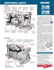
P1276<br />
For <strong>Models</strong>: <strong>L1276</strong>, <strong>M1276</strong>, <strong>and</strong> N<strong>L1276</strong><br />
<strong>PARTS</strong> <strong>CATALOG</strong><br />
Marine Generators | Marine Diesel Engines | L<strong>and</strong>-Based Generators
— CALIFORNIA —<br />
Proposition 65 Warning:<br />
Diesel engine exhaust <strong>and</strong> some of its constituents<br />
are known to the State of Cali<strong>for</strong>nia to cause<br />
cancer, birth defects, <strong>and</strong> other reproductive harm.<br />
<strong>Northern</strong> <strong>Lights</strong><br />
4420 14th Avenue N.W.<br />
Seattle, WA 98107<br />
Tel: (206) 789-3880<br />
Fax: (206) 782-5455<br />
Copyright ©2011 <strong>Northern</strong> <strong>Lights</strong>, Inc.<br />
All rights reserved. <strong>Northern</strong> <strong>Lights</strong>, <strong>and</strong><br />
the <strong>Northern</strong> <strong>Lights</strong> logo are trademarks of<br />
<strong>Northern</strong> <strong>Lights</strong>, Inc.<br />
Printed in U.S.A.<br />
PART NO.: P1276 02/11
<strong>PARTS</strong> <strong>CATALOG</strong><br />
<strong>for</strong> <strong>Models</strong> <strong>L1276</strong>, <strong>M1276</strong>, <strong>and</strong> N<strong>L1276</strong><br />
Please read thoroughly be<strong>for</strong>e attempting to use this manual:<br />
Table of Contents ......................................................I<br />
Model Designation & Serial Numbers ........................II<br />
Reading a Parts Page ...............................................III<br />
Table of Contents<br />
GROUP 1 - ENGINE<br />
Cylinder Block ............................................................0 - 2<br />
Flywheel & Housing ..................................................3 - 4<br />
Crankshaft & Crankshaft Pulley ...............................5 - 11<br />
Cylinder Liner & Connecting Rod ......................... 12 - 17<br />
Timing Gear Cover ................................................. 18 - 21<br />
Oil Filter & Cooler ................................................. 22 - 27<br />
Oil Pump ........................................................................ 28<br />
Oil Pan ............................................................................ 29<br />
Oil Drain ......................................................................... 30<br />
Dipstick .......................................................................... 31<br />
Oil Fill Assembly ........................................................... 32<br />
Camshaft ........................................................................ 33<br />
Cylinder Head ........................................................ 34 - 35<br />
Rocker Arm Assembly & Cover ............................. 36 - 37<br />
GROUP 2 - INTAKE & EXHAUST SYSTEM<br />
Air Intake Manifold & Air Intake Connection ...........0 - 2<br />
“Air Sep” Air Filter .....................................................4 - 7<br />
Air Filter ......................................................................8 - 9<br />
Exhaust Manifold ................................................... 10 - 12<br />
Turbocharger & Mounting ..................................... 14 - 15<br />
Turbocharger Assembly .......................................... 16 - 18<br />
Exhaust Elbows ...................................................... 19 - 20<br />
GROUP 3 - COOLING SYSTEM<br />
Expansion Tank ................................................................ 1<br />
Heat Exchanger & Oil Cooler .....................................2 - 7<br />
Coolant Pump ..............................................................8 - 9<br />
Raw Water Pump & Mounting ............................... 10 - 13<br />
Thermostats, Housing, & Connector ..................... 14 - 17<br />
Fan <strong>and</strong> Drive Assembly ........................................ 18 - 19<br />
Radiator & Charge Air Cooler................................ 20 - 21<br />
P1276 2/11<br />
1<br />
GROUP 4 - FUEL SYSTEM<br />
Electronic Unit Injectors & Controller .................. 0<br />
Fuel Injector Applications ..................................... 1<br />
Electronic Control Unit Applications .................... 2<br />
Fuel Pump ............................................................ 3<br />
Fuel Filter & Lines ...........................................4 - 6<br />
GROUP 5 - ELECTRICAL SYSTEM<br />
Engine Electrical ..............................................0 - 7<br />
Starter .............................................................8 - 11<br />
Alternator & Mounting ................................ 12 - 16<br />
Relay Boards & DC Enclosure .................... 17 - 21<br />
Belt Guard ................................................... 22 - 23<br />
Control Panels ............................................. 24 - 32<br />
Drive Belts .......................................................... 33<br />
GROUP 6 - GASKET SETS<br />
Gasket Kits .......................................................0 - 1<br />
GROUP 7 - GEAR AND ADAPTER SETS<br />
Consult dealer or factory<br />
GROUP 8 - BASE FRAME & MOUNTING<br />
Lifting Eyes ........................................................... 0<br />
Engine Mounting ................................................... 1<br />
Base Frames .....................................................2 - 8<br />
GROUP 9 - ACCESSORIES & OPTIONAL<br />
EQUIPMENT<br />
Auxiliary Drive ..................................................... 1<br />
Low Coolant Level Switch ...............................2 - 3<br />
Raw Water Flow Switch ........................................ 4<br />
Proprietary In<strong>for</strong>mation<br />
This publication is the sole property of <strong>Northern</strong> <strong>Lights</strong>, Inc.<br />
It may not be reproduced in whole or part without the expressed written permission of <strong>Northern</strong> <strong>Lights</strong>, Inc.<br />
© <strong>Northern</strong> <strong>Lights</strong>, Inc. 2009. All rights reserved. Litho U.S.A. Publication number: P1276 09/09
INTRODUCTION<br />
Model Designation<br />
Refer to the category designations below to fi nd the correct parts pages <strong>for</strong> your model.<br />
L, M, NL<br />
L - Lugger propulsion unit<br />
M - Marine generator set<br />
NL - Industrial generator set<br />
L 1276 A<br />
M 1276 A<br />
Serial Numbers<br />
=<br />
=<br />
1276<br />
Base Model #<br />
(Deere 12.5 Liter<br />
Powertech Series<br />
engine block)<br />
<strong>Northern</strong> <strong>Lights</strong> aftercooled propulsion<br />
engine with a John Deere 12.5 liter<br />
engine.<br />
<strong>Northern</strong> <strong>Lights</strong> aftercooled marine engine<br />
with a John Deere 12.5 liter engine.<br />
P1276 2/11<br />
II<br />
A Aftercooled<br />
H High output<br />
All model numbers used in headings will indicate a John Deere base engine. All variations<br />
requiring serial numbers <strong>for</strong> proper identifi cation will be noted as <strong>Northern</strong> <strong>Lights</strong> or John Deere.<br />
NORTHERN LIGHTS<br />
Your set has three serial numbers: 1� an engine number stamped on the block, �2� a generator plate,<br />
<strong>and</strong> �3� a generator set plate. Use the serial number on the generator set plate when ordering parts or<br />
in correspondence. The generator set plate is found on the service side of the generator <strong>and</strong> resembles<br />
one of the drawings below.<br />
Lugger serial number<br />
NL 1276 H<br />
=<br />
A, H<br />
<strong>Northern</strong> <strong>Lights</strong> industrial<br />
engine with a John Deere<br />
12.5 liter engine, high output.<br />
Generator set serial number
5<br />
6<br />
REFERENCES:<br />
1. Grouping section title. 7. Quantity of parts used.<br />
2. Model designation of equipment that uses parts 8. Description of each component part.<br />
listed on this page. 9. Serial number of unit the part fi ts.<br />
3. Title <strong>and</strong> description of assembly. 10. Assembly or kit designated by Key 0 or ••/•.<br />
4. Drawing numbers that correspond to key 11. Grouping index number.<br />
column numbers <strong>for</strong> parts identifi cation. 12. Page number within the grouping index.<br />
5. Key column <strong>for</strong> locating parts shown on drawing. 13. Manual title.<br />
6. Part number. 14. Page publication date.<br />
NOTE: � Arrows always point toward the front of the engine.<br />
P1276 2/11<br />
III<br />
1<br />
Reading a Parts Page<br />
IMPORTANT:<br />
Be<strong>for</strong>e selecting parts, be sure that you are choosing parts from the correct page.<br />
Check the model designation at the page top.<br />
Do not use this illustration <strong>for</strong> parts purchasing.<br />
ELECTRICAL SYSTEM<br />
4 3<br />
2<br />
7 8 9<br />
0<br />
1<br />
185046210<br />
185446219<br />
1<br />
1<br />
Alternator Assembly<br />
Flywheel, complete<br />
10<br />
-<br />
-<br />
2 185446217 1 Plate, complete -<br />
3 185716200 1 Plate -<br />
4 185446218 1 Stator, complete -<br />
5 040126210 2 Bearing -<br />
6 020210010 1 Nut -<br />
7 027100010 1 Spring washer -<br />
8 026100010 1 Washer -<br />
9 185446220 1 Clamp -<br />
10 015140408 1 Screw -<br />
11 015140425 2 Screw -<br />
12 199236510 1 Collar -<br />
13<br />
11<br />
P1276 08/00<br />
5-2<br />
14<br />
12<br />
ALTERNATOR ASSEMBLY: M - N<strong>L1276</strong><br />
KEY PART NUMBER QTY. DESCRIPTION SERIALNUMBER<br />
INTRODUCTION
GROUP 1 – ENGINE<br />
Cylinder Block<br />
Reproduced by permission of Deere & Co., c2005. Deere & Company. All rights reserved.<br />
Updated 3-25-09<br />
P1276 2/11<br />
1 - 0<br />
R625769PCDB02
Updated 3-25-09<br />
P1276 2/11<br />
1 - 1<br />
GROUP 1 – ENGINE<br />
Cylinder Block<br />
KEY PART NUMBER QTY DESCRIPTION DEERE S/N<br />
1 Cylinder Block* (marked R526650) -<br />
2 R116638 6 Bearing Cap, Main up to xxxx-045313<br />
R5185501 6 Bearing Cap, Main from xxxx-045314<br />
R116639 1 Bearing Cap, Thrust up to xxxx-045313<br />
R518573 1 Bearing Cap, Thrust from xxxx-045314<br />
3 R116640 14 Screw up to xxxx-045313<br />
R518579 14 Capscrew from xxxx-045314<br />
4 R502753 2 Expansion Plug -<br />
5 15H690 1 Plug 3/4 NPT -<br />
6 R51133 1 Fitting -<br />
7 T11370 1 Elbow Fitting -<br />
8 T21937 1 Plug -<br />
9 R116466 1 Plug -<br />
10 AT13740 1 Drain Valve -<br />
11 15H685 2 Plug 1/4 NPT -<br />
*Not available separately- see short block listings
GROUP 1 – ENGINE<br />
Short Block<br />
Updated 3-13-09 & 3-25-09<br />
Reproduced by permission of Deere & Co., c2005. Deere & Company. All rights reserved.<br />
KEY PART NUMBER QTY DESCRIPTION DEERE S/N<br />
1 RE68692 1 Short Block Assembly <strong>L1276</strong>A, <strong>M1276</strong>A1 @50 Hz (marked<br />
R116428 or R502884, piston/crown marked RE66125,<br />
replaced by RE528460 & damper)<br />
up to xxxx-053079<br />
RE528460 1 Short Block Assembly <strong>L1276</strong>A, <strong>M1276</strong>A1 @ 50 Hz (marked<br />
R524326, R522822, or R519559) from xxxx-053080-<br />
2 RE524829 1 Short Block Assembly <strong>L1276</strong>A2 all, <strong>M1276</strong>A1 @ 60 Hz,<br />
<strong>M1276</strong>A2 all 50 & 60 Hz (marked R502884 replaced by RE528462<br />
& damper) up to xxxx-053079<br />
RE528462 1 Short Block Assembly <strong>L1276</strong>A2 all, <strong>M1276</strong>A1 @ 60 Hz,<br />
<strong>M1276</strong>A2 all 50 & 60 Hz (marked R522822 <strong>and</strong> R519559) from xxxx-053080<br />
P1276 2/11<br />
1 - 2<br />
RGP4978
Reproduced by permission of Deere & Co., c2005. Deere & Company. All rights reserved.<br />
P1276 2/11<br />
1 - 3<br />
GROUP 1 – ENGINE<br />
Flywheel Housing SAE #1 & SAE #2<br />
KEY PART NUMBER QTY DESCRIPTION SERIAL NUMBER<br />
1 R27149 1 O-ring -<br />
2 AR61533 1 Plug -<br />
3 R35043 1 Gasket -<br />
4 R116338 1 Housing -<br />
5 RE53687 1 Seal -<br />
6 19H2369 4 Capscrew, 3/4” x 1” -<br />
7 R133483 1 Cover -<br />
8 21H1318 2 Machine Screw, #12 x 1/2” -<br />
9 R31493 1 Cover -<br />
10 R67989 1 Gasket -<br />
11 H79910 2 Dowel Pin, 9/16” x 1.752” -<br />
12 R121689 1 Housing (SAE #1) -<br />
R121696 1 Housing (SAE #2) -<br />
13 19H1862 6 Capscrew, 3/4” x 2 -1/2” -<br />
14 R130091 8 Screw, M6 x 12 -<br />
15 19M7868 7 Screw, M8 x 30 -<br />
RGP8088
GROUP 1 – ENGINE<br />
Flywheel, SAE #11-1/2 & SAE #14<br />
Reproduced by permission of Deere & Co., c2005. Deere & Company. All rights reserved.<br />
KEY PART NUMBER QTY DESCRIPTION SERIAL NUMBER<br />
1 RE68953 1 Flywheel Assembly SAE #11-1/2 (marked R133951- includes key #2) -<br />
RE53698 1 Flywheel Assembly SAE #14 (marked R116828 - includes key #2) -<br />
2 AR103044 1 Ring Gear (147 Teeth - #11-1/2 Flywheel) -<br />
R76000 1 Ring Gear (147 Teeth - #14 Flywheel) -<br />
3 R135049 12 Capscrew (SAE #11-1/2 Flywheel) -<br />
R116911 12 Capscrew (SAE #14 Flywheel) -<br />
P1276 2/11<br />
1 - 4<br />
RGP4667
Reproduced by permission of Deere & Co., c2005. Deere & Company. All rights reserved.<br />
P1276 2/11<br />
1 - 5<br />
GROUP 1 – ENGINE<br />
Crankshaft<br />
RGP4662 & RGP4715<br />
KEY PART NUMBER QTY DESCRIPTION SERIAL NUMBER<br />
1 34M7129 1 Spring Pin, 3 x 16 mm -<br />
2 26M4224 1 Shaft Key -<br />
3 R122377 1 Wheel Speed Sensor -<br />
4 R116330 1 Gear -<br />
5 RE51761 1 Crankshaft (marked R116068) -<br />
6 RE63906 1 Thrust Washer (St<strong>and</strong>ard pkg (3) R116299) -<br />
RE68659 1 Thrust Washer (.18 mm [.007”] OS Flange Pkg (2) R133599 & R116299) -<br />
7 RE63905 1 Thrust Bearing (St<strong>and</strong>ard pkg 129751 & R129752) -<br />
RE68663 1 Thrust Bearing (.25 mm [.010”] US pkg R133606 & R133607) -<br />
RE68664 1 Thrust Bearing (.50 mm [.020”] US pkg R133608 & R133609) -<br />
8 RE63903 6 Bearing (St<strong>and</strong>ard pkg R129749 & R129750) -<br />
RE68655 6 Bearing (.25 mm [.010”] US pkg R133600 & R133601) -<br />
RE68656 6 Bearing (.50 mm [.020”] US pkg R133602 & R133603) -
GROUP 1 – ENGINE<br />
Crankshaft Pulley<br />
<strong>L1276</strong>A & A2 Continuous Duty 340 Hp @1800 RPM<br />
<strong>L1276</strong>A2 Medium Duty 425 Hp @2100 RPM<br />
<strong>M1276</strong>A2 Generator 230 kW@1500 RPM<br />
Reproduced by permission of Deere & Co., c2005. Deere & Company. All rights reserved.<br />
KEY PART NUMBER QTY DESCRIPTION SERIAL NUMBER<br />
1 RE54073 1 Seal (Front) -<br />
2 R130091 8 Screw, M6 x 12 mm -<br />
3 RE523266 1 Torsional Damper & Pulley (<strong>for</strong>merly #RE505520) from S/N 053080 -<br />
RE519753 1 Washer (use with RE523266 Damper & Pulley) from S/N 053080 -<br />
4 R133882 1 Hub -<br />
5 19M8088 6 Capscrew, M12 x 75 -<br />
P1276 2/11<br />
1 - 6<br />
RGP7108
Reproduced by permission of Deere & Co., c2006. Deere & Company. All rights reserved.<br />
P1276 2/11<br />
1 - 7<br />
GROUP 1 – ENGINE<br />
Crankshaft Pulley<br />
<strong>L1276</strong>A2 High Output 525 Hp @2100 RPM<br />
KEY PART NUMBER QTY DESCRIPTION SERIAL NUMBER<br />
1 RE54073 1 Seal (Front) -<br />
2 R130091 8 Screw, M6 x 12 mm -<br />
3 RE516281 1 Torsional Damper -<br />
4 R133882 1 Hub -<br />
5 19M8088 6 Capscrew, M12 x 75 -<br />
6 R516399 1 Pulley -<br />
7 19M7818 4 Screw -<br />
RGP9765
GROUP 1 – ENGINE<br />
Crankshaft Pulley<br />
<strong>M1276</strong>A2 280 kW @1800 RPM<br />
Reproduced by permission of Deere & Co., c2006. Deere & Company. All rights reserved.<br />
KEY PART NUMBER QTY DESCRIPTION SERIAL NUMBER<br />
1 RE54073 1 Seal (Front) -<br />
2 R130091 8 Screw, M6 x 12 mm -<br />
3 RE507214 1 Torsional Damper with Pulley (<strong>for</strong>merly #RE50507) up to S/N -053079<br />
RE523268 1 Torsional Damper with Pulley from S/N 053080 -<br />
R519753 1 Spacer (use with RE523268 - not shown) -<br />
4 R133882 1 Hub -<br />
5 19M8088 6 Capscrew, M12 x 75 -<br />
P1276 2/11<br />
1 - 8<br />
RGP7108
Reproduced by permission of Deere & Co., c2006. Deere & Company. All rights reserved.<br />
P1276 2/11<br />
1 - 9<br />
GROUP 1 – ENGINE<br />
Crankshaft Pulley<br />
N<strong>L1276</strong>H2 Power Unit 450 Hp @1800 RPM<br />
KEY PART NUMBER QTY DESCRIPTION SERIAL NUMBER<br />
1 RE54073 1 Seal (Front) -<br />
2 R130091 8 Screw, M6 x 12 mm -<br />
3 RE65565 1 Torsional Damper -<br />
4 R501561 1 Hub -<br />
5 19M7818 6 Capscrew, M12 x 80 -<br />
6 R133879 1 Pulley -<br />
7 19M7818 4 Screw, M12 x 80 -<br />
RGP7106
GROUP 1 – ENGINE<br />
Crankshaft Pulley<br />
N<strong>L1276</strong>H1 285 Hp @1800 RPM<br />
Reproduced by permission of Deere & Co., c2006. Deere & Company. All rights reserved.<br />
KEY PART NUMBER QTY DESCRIPTION Deere S/N<br />
1 RE54073 1 Seal (Front) -<br />
2 R130091 8 Screw, M6 x 12 mm -<br />
3 RE505507 1 Torsional Damper up to - 031576<br />
RE507214 1 Torsional Damper with Pulley from 031577 -<br />
4 R501561 1 Hub -<br />
5 19M7818 6 Capscrew, M12 x 80 -<br />
6 R133880 1 Pulley -<br />
7 19M7818 4 Screw -<br />
P1276 2/11<br />
1 - 10<br />
RGP7107
Reproduced by permission of Deere & Co., c2006. Deere & Company. All rights reserved.<br />
P1276 2/11<br />
1 - 11<br />
GROUP 1 – ENGINE<br />
Crankshaft Pulley<br />
N<strong>L1276</strong>H3 330 kW @1800 RPM<br />
RGP7113<br />
KEY PART NUMBER QTY DESCRIPTION SERIAL NUMBER<br />
1 RE54073 1 Seal (Front) -<br />
2 R130091 8 Screw, M6 x 12 mm -<br />
3 RE505507 1 Torsional Damper up to - 031576<br />
RE507214 1 Torsional Damper with Pulley from 031577 -<br />
4 R501561 1 Hub -<br />
5 19M7818 6 Capscrew, M12 x 80 -
GROUP 1 – ENGINE<br />
<strong>L1276</strong>A - All, <strong>M1276</strong>A All, <strong>M1276</strong>A1 All<br />
Updated 3-24-09<br />
Cylinder Liner Assembly <strong>and</strong> Connecting Rod<br />
Reproduced by permission of Deere & Co., c2005. Deere & Company. All rights reserved.<br />
P1276 2/11<br />
1 - 12<br />
RGP7222
P1276 2/11<br />
1 - 13<br />
<strong>L1276</strong>A - All, <strong>M1276</strong>A All, <strong>M1276</strong>A1 All<br />
KEY PART NUMBER QTY DESCRIPTION Deere S/N<br />
1 N51168 12 Snap Ring -<br />
2 R64451 6 Piston Pin -<br />
3 R66453 12 Capscrew (use with Connecting Rod RE57641) up to xxxx-010513<br />
R501380 12 Capscrew (use with Connecting Rod marked R519614) from xxxx-010514<br />
4 R69045 6 Bushing (marked R63960) -<br />
5 RE57641 6 Connecting Rod (marked R121174, substitute SE500502) up to xxxx-010513<br />
SE500502 6 Connecting Rod (remanufactured <strong>for</strong> RE57641) up to xxxx-010513<br />
RE522978 6 Connecting Rod (marked R519614 or R501566, 2 notches, xxxx-101514 to<br />
replaces RE502314) xxxx-057910<br />
RE532355 6 Connecting Rod (marked R519614 or R526175, 1 notch) from xxxx-057911<br />
SE501066 6 Connecting Rod (remanufactured <strong>for</strong> RE502314)<br />
6 RE63811 ** Bearing (Std., use with Rods marked R524613 or R501566, 2 notches) xxxx-010514 to<br />
xxxx-057910<br />
RE68703 ** Bearing (.25 mm [.010”] US, use with Rods marked R524613 or R501566, xxxx- 010514 to<br />
2 notches) xxxx-057910<br />
RE68704 ** Bearing (.50 mm [.020”] US, use with Rods marked R524613 or R501566, xxxx- 010514 to<br />
2 notches) xxxx-057910<br />
RE530787 ** Bearing Kit (Std., use with Rods marked R519614 or R526175,<br />
one notch)<br />
from xxxx-057911<br />
RE531768 ** Bearing Kit (.25 mm [.010”] US, 1 notch) from xxxx-057911<br />
RE531769 ** Bearing Kit (.50 mm [.020”] US, 1 notch) from xxxx-057911<br />
RE534626 ** Bearing Kit (Std., use with Rods marked R121174) up to xxxx-010513<br />
RE534627 ** Bearing Kit (.25 mm [.010”] US, use with Rods marked R121174) up to xxxx-010513<br />
RE534628 ** Bearing Kit (.50 mm [.020”] US, use with Rods marked R121174) up to xxxx-010513<br />
7 RE504630 6 Piston Ring Kit (use with Piston Liner marked RE503969) from xxxx-030000<br />
RE53637 6 Piston Ring Kit (use with Piston Liner marked RE66125) up to xxxx-010908<br />
RE504630 6 Piston Ring Kit from xxxx-010909<br />
8 AR72351 6 O-ring Kit -<br />
9 RE506961 6 Piston Liner Kit (marked RE505901) from xxxx-030000<br />
RE66216 6 Piston Liner Kit (marked RE66125) up to xxxx-010908<br />
RE505213 6 Piston Liner Kit (marked RE503969) from xxxx-010909<br />
10 R81276 ** Shim (.05 mm [.002”] ) -<br />
R81277 ** Shim (.10 mm [.004”] ) -<br />
11 R48317 12 Sleeve (use with Rod RE57641, marked R121174) -<br />
**As required<br />
Updated 3-24-09<br />
GROUP 1 – ENGINE<br />
Cylinder Liner Assembly <strong>and</strong> Connecting Rod
GROUP 1 – ENGINE<br />
Updated 3-24-09<br />
Cylinder Liner Assembly <strong>and</strong> Connecting Rod<br />
<strong>L1276</strong>A2 @ 340 Hp, <strong>L1276</strong>A2 @ 425 Hp, <strong>M1276</strong>A2 All, N<strong>L1276</strong>H1/ H2/ H3<br />
Reproduced by permission of Deere & Co., c2005. Deere & Company. All rights reserved.<br />
P1276 2/11<br />
1 - 14<br />
RGP7222
KEY PART NUMBER QTY DESCRIPTION Deere S/N<br />
1 N51168 12 Snap Ring -<br />
2 R64451 6 Piston Pin -<br />
3 R501380 12 Capscrew, 12 PT. 5/8-18 x 2-9/16” (Special) -<br />
4 R69045 6 Bushing (marked R63960) -<br />
5 RE522978 6 Connecting Rod (marked R519614 or R501566, 2 notches) up to xxxx-057910<br />
RE532355 6 Connecting Rod (marked R519614 or R526175, 1 notch) from xxxx-057911<br />
SE501066 6 Connecting Rod (remanufactured <strong>for</strong> RE502314)<br />
6 RE63811 ** Bearing (Std., use with Rods marked R501566 or R519614, 2 notches) up to xxxx-057910<br />
RE68703 ** Bearing (.25 mm [.010”] US, use with Rods marked R501566 or R519614, up to xxxx-057910<br />
2 notches)<br />
RE68704 ** Bearing (.50 mm [.020”] US, use with Rods marked R501566 or R519614, up to xxxx-057910<br />
2 notches)<br />
RE530787 ** Bearing Kit (Std., use with Rods marked R519614 or R526175,<br />
one notch)<br />
from xxxx-057911<br />
RE531768 ** Bearing Kit (.25 mm [.010”] US, use with Rods marked R519614 or<br />
R526175, 1 notch)<br />
from xxxx-057911<br />
RE531769 ** Bearing Kit (.50 mm [.020”] US, use with Rods marked R519614 or<br />
R526175, 1 notch)<br />
from xxxx-057911<br />
7 RE515941 6 Piston Ring Kit from xxxx-030000<br />
8 AR72351 6 O-ring Kit -<br />
9 RE506961 6 Piston Liner Kit (marked RE515356, RE517209, or RE524325) from xxxx-030000<br />
10 R81276 ** Shim (.05 mm [.002”] ) -<br />
R81277 ** Shim (.10 mm [.004”] ) -<br />
**As required<br />
Updated 3-24-09<br />
P1276 2/11<br />
1 - 15<br />
GROUP 1 – ENGINE<br />
Cylinder Liner Assembly <strong>and</strong> Connecting Rod<br />
<strong>L1276</strong>A2 @ 340 Hp, <strong>L1276</strong>A2 @ 425 Hp, <strong>M1276</strong>A2 All, N<strong>L1276</strong>H1/ H2/ H3
GROUP 1 – ENGINE<br />
Cylinder Liner Assembly <strong>and</strong> Connecting Rod<br />
<strong>L1276</strong>A2 525 Hp @ 2100 RPM<br />
Reproduced by permission of Deere & Co., c2005. Deere & Company. All rights reserved.<br />
P1276 2/11<br />
1 - 16<br />
RGP7222
KEY PART NUMBER QTY DESCRIPTION Deere S/N<br />
1 N51168 12 Snap Ring -<br />
2 R64451 6 Piston Pin -<br />
3 R501380 12 Capscrew, 12 Pt 5/18-18 x 2-9/16” (Special) -<br />
4 R69045 6 Bushing (marked R63960) -<br />
5 RE522978 6 Connecting Rod (marked R501566 or R519614, two notches) up to xxxx-057910<br />
RE532355 6 Connecting Rod (marked R519614 or R526175, one notch) from xxxx-057911<br />
SE501066 6 Connecting Rod (remanufactured <strong>for</strong> RE502314) -<br />
6 RE63811 ** Bearing (Std., use with Rods marked R501566 or R519614, two notches) up to xxxx-057910<br />
RE68703 ** Bearing (.25 mm [.010”] US, use with Rods marked R501566 or R519614, up to xxxx-057910<br />
two notches)<br />
RE68704 ** Bearing (.50 mm [.020”] US, use with Rods marked R501566 or R519614, up to xxxx-057910<br />
two notches)<br />
RE530787 ** Bearing Kit (Std., use with Rods marked R519614 or R526175,<br />
one notch)<br />
from xxxx-057911<br />
RE531768 ** Bearing Kit (.25 mm [.010”] US, use with Rods marked R519614 or<br />
R526175, one notch)<br />
from xxxx-057911<br />
RE531769 ** Bearing Kit (.50 mm [.020”] US, use with Rods marked R519614 or<br />
R526175, one notch)<br />
from xxxx-057911<br />
7 RE515941 1 Piston Ring Kit -<br />
8 AR72351 6 O-ring Kit -<br />
9 RE515942 6 Piston Liner Kit (marked RE515356, RE517209, or RE524325) -<br />
10 R81276 ** Shim (.05 mm [.002”] ) -<br />
R81277 ** Shim (.10 mm [.004”] ) -<br />
**As required<br />
Updated 3-24-09<br />
P1276 2/11<br />
1 - 17<br />
GROUP 1 – ENGINE<br />
Cylinder Liner Assembly <strong>and</strong> Connecting Rod<br />
<strong>L1276</strong>A2 525 Hp @ 2100 RPM
GROUP 1 – ENGINE<br />
Timing Gear Cover <strong>and</strong> Front Plate<br />
<strong>L1276</strong>A & L- <strong>M1276</strong>A1, A2, A3<br />
Reproduced by permission of Deere & Co., c2005. Deere & Company. All rights reserved.<br />
P1276 2/11<br />
1 - 18<br />
RGP7183
P1276 2/11<br />
1 - 19<br />
Timing Gear Cover <strong>and</strong> Front Plate<br />
<strong>L1276</strong>A & L- <strong>M1276</strong>A1, A2, A3<br />
KEY PART NUMBER QTY DESCRIPTION SERIAL NUMBER<br />
1 R500212 1 Gasket -<br />
N102039 4 Cap -<br />
2 R501741 1 Plate (marked R128730) -<br />
3 R502026 1 V-ring Seal, M10 x 25 -<br />
4 19M8551 5 Screw, M10 x 25 mm -<br />
5 R26333 1 Washer -<br />
6 19M7488 1 Capscrew, M16 x 40 mm -<br />
7 R43696 3 Washer -<br />
8 R119157 1 Cover -<br />
9 19M8738 3 Capscrew -<br />
10 RE53911 3 Gear, Idler -<br />
11 R501309 1 Plate -<br />
12 19M7867 1 Screw -<br />
13 19M7836 2 Screw, M10 x 110 mm -<br />
14 19M7786 2 Screw, M10 x 30 mm -<br />
15 19M7812 6 Screw -<br />
16 14M7296 1 Flange Nut, M10 -<br />
17 R129809 1 Cover, Camshaft -<br />
18 R502441 1 V-ring Seal -<br />
19 R131660 1 Drain Plug -<br />
20 T74492 1 O-ring -<br />
21 R502530 1 Cover (replaced by R506150 & 2 ea. 19M8528) -<br />
R506150 1 Cover (supercedes R502530) -<br />
22 19M8528 7 Screw, M10 x 55 -<br />
23 19M7836 2 Screw, M10 x 110 (use with R502530) -<br />
19M8528 2 Screw, M10 x 55 (use with R506150) -<br />
24 19M8114 1 Screw, M10 x 70 -<br />
25 R120801 1 Dipstick Tube -<br />
26 RE500250 1 Filler Cap -<br />
27 R119159 1 Bolt -<br />
GROUP 1 – ENGINE
GROUP 1 – ENGINE<br />
Timing Gear Cover <strong>and</strong> Front Plate<br />
N<strong>L1276</strong>H1, H2, H3<br />
Reproduced by permission of Deere & Co., c2006. Deere & Company. All rights reserved.<br />
P1276 2/11<br />
1 - 20<br />
RGP7177
P1276 2/11<br />
1 - 21<br />
GROUP 1 – ENGINE<br />
Timing Gear Cover <strong>and</strong> Front Plate<br />
N<strong>L1276</strong>H1, H2, H3<br />
KEY PART NUMBER QTY DESCRIPTION DEERE S/N<br />
1 R500212 1 Gasket -<br />
N102039 4 Cap -<br />
2 R501740 1 Plate (marked R500117) -<br />
N102039 1 Plug -<br />
3 R502026 1 V-ring Seal, M10 x 25 -<br />
4 19M8551 5 Screw, M10 x 25 mm -<br />
5 R26333 1 Washer -<br />
6 19M7488 1 Capscrew, M16 x 40 mm -<br />
7 19M7867 3 Screw, M8 x 25 mm -<br />
8 R119157 1 Cover, M10 x 45 mm -<br />
9 19M8738 3 Capscrew -<br />
10 RE53911 3 Gear, Idler -<br />
11 R501309 1 Plate -<br />
12 19M7836 1 Screw, M10 x 110 mm -<br />
13 19M7786 2 Screw, M10 x 30 mm -<br />
14 19M7812 6 Screw, M10 x 100 mm -<br />
15 14M7296 1 Flange Nut, M10 -<br />
16 R129809 1 Cover, Camshaft -<br />
17 R502441 1 V-ring Seal -<br />
18 19M7836 2 Screw, M10 x 110 mm (use with cover #R502470) up to - 033732<br />
19M8528 2 Screw, M10 x 55 mm (use with cover #R506149) from 033733 -<br />
19 19M8528 7 Screw, M10 x 55 mm -<br />
19M8114 1 Screw -<br />
20 R119159 1 Bolt -<br />
21 R502470 1 Cover (replaced by R506149 & 2 ea. 19M8528) up to - 033732<br />
R506149 1 Cover from 033733 -<br />
22 T70176 1 O-ring -<br />
23 R126926 1 Camshaft Cover -<br />
24 R136091 2 Screw -<br />
25 R43696 3 Washer -
GROUP 1 – ENGINE<br />
Oil Filter <strong>and</strong> Cooler<br />
<strong>L1276</strong>A-A2, <strong>M1276</strong>A1, A2, A3, N<strong>L1276</strong> All<br />
Reproduced by permission of Deere & Co., c2005. Deere & Company. All rights reserved.<br />
P1276 2/11<br />
1 - 22<br />
RGP4800
KEY PART NUMBER QTY DESCRIPTION SERIAL NUMBER<br />
1 RE500657 1 Oil Cooler -<br />
2 R134716 2 O-ring -<br />
3 R500209 1 Gasket -<br />
4 RE71255 1 Pipe Plug -<br />
5 R116854 1 Housing -<br />
6 15H624 1 Pipe Plug, 1/2” -<br />
7 R55233 1 Pipe Plug (sub <strong>for</strong> AT13740) -<br />
8 19M8574 2 Screw, M10 x 85 mm -<br />
9 R500210 1 Gasket -<br />
10 RE515304 1 Housing (marked RE503400 or R503714, sub <strong>for</strong> RE505883, includes<br />
key #20) -<br />
11 21-00132 1 Bushing 1/4 NPT x 1/8 NPT -<br />
12 R127208 1 Adapter -<br />
13 RE58935 1 Oil Filter -<br />
14 R500055 2 Valve, Bypass -<br />
15 R98064 2 Spring -<br />
16 U17409 3 O-ring -<br />
17 R500232 3 Fitting Plug -<br />
18 19M7810 1 Screw, M10 x 80 mm -<br />
19 19M7958 7 Screw, M10 x 150 mm -<br />
20 1 Bushing (not available separately - use RE515304) -<br />
R40750 ** Washer -<br />
21 R124186 1 Relief Valve, Pressure Regulating -<br />
22 R130717 1 Spring -<br />
23 R63532 1 Valve -<br />
24 T31636 1 Spring -<br />
25 R26375 1 O-ring -<br />
26 R33138 1 Fitting -<br />
27 21-51905 ** Plug, Socket Head 1/4 NPT -<br />
28 R136500 2 Nut -<br />
29 RE167207 1 Engine Oil Pressure Sensor (replaces RE56009) -<br />
**As required<br />
P1276 2/11<br />
1 - 23<br />
GROUP 1 – ENGINE<br />
Oil Filter <strong>and</strong> Cooler<br />
<strong>L1276</strong>A-A2, <strong>M1276</strong>A1, A2, A3, N<strong>L1276</strong> All
GROUP 1 – ENGINE<br />
Oil Filter <strong>and</strong> Cooler<br />
L- <strong>M1276</strong><br />
Reproduced by permission of Deere & Co., c2006. Deere & Company. All rights reserved.<br />
P1276 2/11<br />
1 - 24<br />
RGP9813a
P1276 2/11<br />
1 - 25<br />
L- <strong>M1276</strong><br />
KEY PART NUMBER QTY DESCRIPTION SERIAL NUMBER<br />
1 23-09713 1 Bracket -<br />
2 T76938 2 O-ring -<br />
3 21-79705 2 Male Elbow 90 0 Steel 1” O-ring Port -<br />
4 R29936 2 O-ring -<br />
5 R39741 1 Drain Plug -<br />
6 U13639 2 O-ring -<br />
7 T78612 2 O-ring -<br />
8 21-79711 1 Male Elbow 45 0 Steel 1-1/4” O-ring Port -<br />
9 R504011 1 Adapter, Right H<strong>and</strong> Oil Filter Mtg. -<br />
10 R500055 2 Valve -<br />
11 R98064 2 Spring -<br />
12 U17409 3 O-ring -<br />
13 R500232 3 Fitting Plug -<br />
14 R36636 1 Fitting Plug -<br />
16 R127208 1 Adapter -<br />
17 RE58935 1 Oil Filter L, M, N<strong>L1276</strong> -<br />
18 RE500657 1 Oil Cooler -<br />
19 R134716 2 O-ring -<br />
20 R500209 1 Gasket -<br />
21 RE71255 1 Pipe Plug -<br />
22 R116854 1 Housing -<br />
23 RE57836 3 Pipe Plug 1/2” -<br />
24 R55233 1 Pipe Plug -<br />
25 19M8574 2 Screw -<br />
26 21-79706 1 Male Elbow, 90 0 Steel 1-1/4” O-ring Port -<br />
27 A4925R 1 Fitting -<br />
28 R55233 2 Pipe Plug -<br />
29 19M7810 1 Capscrew, Hex Head Flanged M10 x 1.5 x 80 mm -<br />
30 19M7958 6 Screw (2 ea. per pack) -<br />
31 19M8598 1 Capscrew, Hex Head Flanged M10 x 1.5 x 170 mm -<br />
32 RE504758 1 Housing -<br />
34 R124186 1 Pressure Relief Valve -<br />
35 R130717 1 Spring -<br />
36 R63532 1 Valve -<br />
37 T31636 1 Spring -<br />
38 R26375 1 O-ring -<br />
39 R33138 1 Fitting -<br />
40 18-09701 1 Hose Assembly 7/8” x 77-1/2” -<br />
41 18-09702 1 Hose Assembly 1-1/8” I.D. x 63” -<br />
42 R500210 1 Gasket -<br />
GROUP 1 – ENGINE<br />
Oil Filter <strong>and</strong> Cooler
GROUP 1 – ENGINE<br />
Oil Filter <strong>and</strong> Cooler<br />
N<strong>L1276</strong>H2 Power Unit<br />
Reproduced by permission of Deere & Co., c2006. Deere & Company. All rights reserved.<br />
P1276 2/11<br />
1 - 26<br />
RGP9813
P1276 2/11<br />
1 - 27<br />
N<strong>L1276</strong>H2 Power Unit<br />
KEY PART NUMBER QTY DESCRIPTION SERIAL NUMBER<br />
1 R50400 1 Bracket -<br />
2 T76938 2 O-ring -<br />
3 38H1008 1 Elbow Fitting (also order o-rings #T78612 <strong>and</strong> U13639) -<br />
4 R29936 2 O-ring -<br />
5 R39741 1 Drain Plug -<br />
7 T78612 2 O-ring -<br />
8 38H1165 1 Adapter Fitting -<br />
9 R504011 1 Adapter, Right H<strong>and</strong> Oil Filter Mtg. -<br />
10 R500055 2 Valve -<br />
11 R98064 2 Spring -<br />
12 U17409 3 O-ring -<br />
13 R500232 3 Fitting Plug -<br />
14 R36636 1 Fitting Plug -<br />
15 19M7908 4 Capscrew, M12 x 110 mm<br />
16 R127208 1 Adapter, 24 mm x 67 mm -<br />
17 RE58935 1 Oil Filter -<br />
18 RE500657 1 Oil Cooler -<br />
19 R134716 2 O-ring -<br />
20 R500209 1 Gasket -<br />
21 RE71255 1 Pipe Plug -<br />
22 R116854 1 Housing -<br />
23 RE57836 3 Pipe Plug 1/2” -<br />
24 R55233 1 Pipe Plug -<br />
25 19M8574 2 Screw, M10 x 85 mm -<br />
26 61H1165 1 Screw -<br />
27 A4925R 1 Fitting -<br />
28 R55233 2 Pipe Plug -<br />
29 19M7810 1 Capscrew, Hex Head Flanged M10 x 1.5 x 80 mm -<br />
30 19M7958 6 Screw, M10 x 150 mm -<br />
31 19M8598 1 Capscrew, Hex Head Flanged M10 x 1.5 x 170 mm -<br />
32 RE504758 1 Housing -<br />
R43549 ** Washer -<br />
33 RE504758 1 Housing (marked R501537) -<br />
34 R124186 1 Pressure Relief Valve -<br />
35 R130717 1 Spring -<br />
36 R63532 1 Valve -<br />
37 T31636 1 Spring -<br />
38 R26375 1 O-ring -<br />
39 R33138 1 Fitting -<br />
40 RE505983 1 Tube, Outlet -<br />
41 RE508345 1 Bracket -<br />
43 19M8318 1 Screw, M8 x 45 mm -<br />
44 U46753 1 Hose Clamp -<br />
45 RE505982 1 Tube, Inlet -<br />
46 R136500 2 Nut -<br />
47 R500210 1 Gasket -<br />
GROUP 1 – ENGINE<br />
Oil Filter <strong>and</strong> Cooler
GROUP 1 – ENGINE<br />
Oil Pump<br />
Reproduced by permission of Deere & Co., c2005. Deere & Company. All rights reserved.<br />
P1276 2/11<br />
1 - 28<br />
RGP4693<br />
KEY PART NUMBER QTY DESCRIPTION DEERE S/N<br />
1 R500387 1 Gasket -<br />
2 RE501880 1 Oil Pump (contains [4] 19M8675, sub RE502752) up to - 031394<br />
RE502752 1 Oil Pump (contains [4] 19M8675) from 031395 -<br />
3 19M8508 3 Screw, M8 x 80 -<br />
4 RE53654 1 Gear -<br />
5 40M7076 1 Snap Ring -
Reproduced by permission of Deere & Co., c2005. Deere & Company. All rights reserved.<br />
KEY PART NUMBER QTY DESCRIPTION SERIAL NUMBER<br />
1 R126783 1 Gasket -<br />
2 RE68429 1 Oil Pump Intake -<br />
3 19M7866 3 Screw, M8 x 20 mm -<br />
4 R36636 1 Fitting Plug -<br />
5 R29936 1 O-ring -<br />
6 RE521549 1 Gasket -<br />
7 R128780 1 Oil Pan -<br />
8 19M8528 8 Screw, M10 x 55 mm -<br />
9 19M7835 22 Screw, M10 x 35 mm -<br />
10 R27175 4 Drain Plug -<br />
11 R56751 4 O-ring -<br />
P1276 2/11<br />
1 - 29<br />
GROUP 1 – ENGINE<br />
Oil Pan<br />
RGP5365
GROUP 1 – ENGINE<br />
Oil Drain <strong>M1276</strong><br />
Corrected page 12-4-07<br />
P1276 2/11<br />
1 - 30<br />
A-10240 / B-9349<br />
KEY PART NUMBER QTY DESCRIPTION SERIAL NUMBER<br />
1 21-79701 1 Male Elbow, 90 0 Steel -<br />
2 36-70008 1 Ball Valve, Brass 3/4 NPT -<br />
3 21-12803 1 Male Connector, Steel 3/4 NPT x 3/4-37T -<br />
4 21-71059 2 Female Swivel, Brass 3/4 HB x 3/4-37T -<br />
5 41-00002 20” Hose, 3/4” I.D., Push-on -<br />
6 21-64801 1 Male Elbow, 90 0 Steel 3/4 NPT x 3/4-37T -<br />
7 21-12530 1 Plug, Hex Head Brass 3/4 NPT -
KEY PART NUMBER QTY DESCRIPTION SERIAL NUMBER<br />
1 RE521521 1 Dipstick (Center, Right h<strong>and</strong>, <strong>for</strong>merly #RE66583) -<br />
2 A4925R 1 Male Connector, Brass 1/4 NPT x 3/8- 45T -<br />
3 R130049 1 Dipstick Tube* -<br />
4 A4926R 1 Tube Nut, Short Brass 3/8- 45T -<br />
15H685 ** Pipe Plug 1/4” (<strong>for</strong> unused locations) -<br />
*Note: Dipstick tube is replaced by new #RE526276 <strong>and</strong> dipstick<br />
#RE525818.<br />
**As required.<br />
P1276 2/11<br />
1 - 31<br />
GROUP 1 – ENGINE<br />
Oil Dipstick<br />
RGP4907
GROUP 1 – ENGINE<br />
Oil Fill Assembly<br />
Reproduced by permission of Deere & Co., c2005. Deere & Company. All rights reserved.<br />
P1276 2/11<br />
1 - 32<br />
RGP5360<br />
KEY PART NUMBER QTY DESCRIPTION SERIAL NUMBER<br />
1 RE500250 1 Filler Cap -<br />
2 19M7804 2 Screw, M10 x 40 mm -<br />
3 RE505718 1 Tube ( L.H. Rear) -<br />
4 AR44217 2 Clamp -<br />
5 R133758 1 Hose -<br />
6 AU14063 1 Hose Fitting -<br />
7 R29936 3 O-ring -<br />
8 R36636 3 Fitting Plug -
Reproduced by permission of Deere & Co., c2005. Deere & Company. All rights reserved.<br />
KEY PART NUMBER QTY DESCRIPTION SERIAL NUMBER<br />
1 R500211 1 Gasket -<br />
2 R62976 1 O-ring -<br />
3 R119158 1 Ring -<br />
4 19M7867 6 Capscrew, M8 x 25 -<br />
5 R116526 1 Gear -<br />
6 R119575 1 Bushing -<br />
7 R116911 6 Capscrew -<br />
8 R134706 4 Bushing -<br />
9 R117021 1 Coupling -<br />
10 R502027 1 Spider -<br />
11 R117020 1 Pin -<br />
12 RE506962 1 Camshaft (marked R503970, includes key #11) -<br />
P1276 2/11<br />
1 - 33<br />
GROUP 1 – ENGINE<br />
Camshaft<br />
RGP7164
GROUP 1 – ENGINE<br />
Cylinder Head<br />
Reproduced by permission of Deere & Co., c2005. Deere & Company. All rights reserved.<br />
P1276 2/11<br />
1 - 34<br />
RGP7163
Updated 9-4-08 & 9-8-08<br />
P1276 2/11<br />
1 - 35<br />
Cylinder Head<br />
KEY PART NUMBER QTY DESCRIPTION SERIAL NUMBER<br />
1 RE518347 1 Cylinder Head (marked R504243) -<br />
2 ** Spring -<br />
3 RE505499 24 Kit -<br />
4 RE66635 24 Seal -<br />
5 R517011 24 Sleeve -<br />
6 R134706 4 Bushing -<br />
7 R504713 24 Valve Seat Insert (St<strong>and</strong>ard) -<br />
R133637 ** Valve Seat Insert (.25 mm [.010”] OS)<br />
8 R516892 12 Exhaust Valve (Exhaust, St<strong>and</strong>ard) -<br />
9 R516892 12 Exhaust Valve (Intake, St<strong>and</strong>ard) -<br />
10 M1206T 7 Cap (38 mm OD) -<br />
11 15H690 5 Pipe Plug, 3/4” -<br />
12 R504174 3 Plug -<br />
AT107509 1 Plug<br />
13 N102039 6 Cap (25 mm OD) -<br />
14 34H309 4 Spring Pin, 1/4” x 5/8” -<br />
15 RE518339 6 Sleeve -<br />
16 T122075 6 O-ring -<br />
17 RE57784 1 Engine Cylinder Head Gasket -<br />
18 R129645 26 Washer* -<br />
19 R519524 26 Capscrew* (<strong>for</strong>merly #R132103) -<br />
20 R91889 48 Retainer -<br />
*Included in Head Bolt kit RE530817 (<strong>for</strong>merly #RG28087)<br />
**As required<br />
GROUP 1 – ENGINE
GROUP 1 – ENGINE<br />
Rocker Arm & Shaft Assembly<br />
Reproduced by permission of Deere & Co., c2005. Deere & Company. All rights reserved.<br />
KEY PART NUMBER QTY DESCRIPTION SERIAL NUMBER<br />
1 R130595 2 Clamp (also order [2] R136507) -<br />
2 30M7010 4 Cap -<br />
3 RE66193 2 Rocker Arm Shaft -<br />
4 R136507 12 Screw -<br />
5 R136507 2 Screw -<br />
6 R130501 2 Clamp (also order R136507) -<br />
7 R500145 12 Nut -<br />
8 R116556 12 Screw -<br />
9 RE53416 6 Rocker Arm, Intake -<br />
10 R130643 6 Nut -<br />
11 R115516 6 Screw -<br />
12 RE508660 6 Rocker Arm, Injector -<br />
13 RE53420 6 Rocker Arm, Exhaust -<br />
14 R117069 12 Push Rod -<br />
15 RE503824 12 Crossbar -<br />
16 RE508659 1 Rocker Arm -<br />
P1276 2/11<br />
1 - 36<br />
RGP7162
Reproduced by permission of Deere & Co., c2005. Deere & Company. All rights reserved.<br />
P1276 2/11<br />
1 - 37<br />
GROUP 1 – ENGINE<br />
Rocker Arm Cover<br />
RGP5334<br />
KEY PART NUMBER QTY DESCRIPTION DEERE S/N<br />
1 19M8039 3 Screw, M8 x 80 mm -<br />
2 RE71265 3 Isolator -<br />
3<br />
4<br />
5<br />
R120467<br />
AR21839<br />
TY22450<br />
1<br />
1<br />
**<br />
Elbow Fitting<br />
} Clamp<br />
Industrial Only<br />
Bulk Hose<br />
-<br />
-<br />
-<br />
6 R72328 1 O-ring -<br />
7 R116843 1 Valve Cover up to - 014582<br />
R505450 1 Valve Cover from 014583 -<br />
8 R63185 1 O-ring -<br />
9 RE66329 1 Defl ector -<br />
10 R130738 1 Gasket up to - 014582<br />
R521520 1 Gasket (<strong>for</strong>merly #R502124) from 014583 -<br />
11 R130091 2 Screw, M6 x 12 mm -<br />
12 R501292 2 Bushing -<br />
13 1 Label -<br />
**As required
GROUP 2 – INTAKE AND EXHAUST SYSTEM<br />
Intake Manifold & Air Intake Connection Assembly<br />
Reproduced by permission of Deere & Co., c2005. Deere & Company. All rights reserved.<br />
P1276 2/11<br />
2 - 0<br />
A-10366, A-10457/ RGP8339a
P1276 2/11<br />
2 - 1<br />
GROUP 2 – INTAKE AND EXHAUST SYSTEM<br />
Intake Manifold & Air Intake Connection Assembly<br />
KEY PART NUMBER QTY DESCRIPTION SERIAL NUMBER<br />
1 RE62249 1 Aftercooler & Intake Manifold -<br />
2 21-31003 2 Pipe Plug 3/8 NPT -<br />
3 RE46684 1 Plug -<br />
4 16-00005 1 O-ring -<br />
5 R116830 1 Gasket -<br />
6 19M7866 14 Capscrew M8 x 20 -<br />
7 R523240 3 Hose (<strong>for</strong>merly #R129608) -<br />
8 21-31616 1 Male Connector, Steel 1/2 NPT x 3/4 Hose Barb -<br />
9 19-01012 8 Clamp #12 -<br />
10 R129702 1 Tube, Outlet -<br />
11 21-31616 1 Male Connector, Steel 1/2 NPT x 3/4 Hose Barb -<br />
12 R129607 1 Hose -<br />
13 R502193 1 Tube, Inlet -<br />
14 21-10002 1 Drain Valve -<br />
15 R502194 1 Clamp -<br />
16 19M7785 1 Capscrew, Hex Head Flanged M10 x 1.5 x 25 mm -<br />
17 18-24801 1 Hose, 3” ID x 3” 6 Ply Silicone -<br />
18 19-02044 2 Hose Clamp #44 -<br />
19 27-29701 1 Tube, Air Intake -<br />
20 16-25002 2 O-ring -<br />
21 10-24806 2 Elbow, Air Inlet -<br />
22 16-25002 2 O-ring -<br />
23 00-24802 3 Clamp Dog -<br />
24 12-00312 3 Capscrew, Hex Head 3/8-16 x 1” -<br />
25 15-00302 3 Lock Washer 3/8” -
GROUP 2 – INTAKE AND EXHAUST SYSTEM<br />
Intake Manifold<br />
N<strong>L1276</strong><br />
Reproduced by permission of Deere & Co., c2006. Deere & Company. All rights reserved.<br />
P1276 2/11<br />
2 - 2<br />
RGP7209<br />
KEY PART NUMBER QTY DESCRIPTION SERIAL NUMBER<br />
1 R516998 1 Cover -<br />
2 R116830 1 Gasket -<br />
3 15H666 1 Pipe Plug -<br />
4 19M8006 4 Screw, M8 x 120 -<br />
5 19M7803 10 Screw, M8 x 70 -<br />
6 T75197 2 Clamp -<br />
7 RE61812 1 Sensor -<br />
8 24M7055 2 Washer -<br />
9 RE71255 ** Pipe Plug -<br />
**As required
P1276 2/11<br />
2 - 3<br />
GROUP 2 – INTAKE AND EXHAUST SYSTEM<br />
Notes
GROUP 2 – INTAKE AND EXHAUST SYSTEM<br />
“Air-Sep” Air Filter<br />
Early Production<br />
Amended 1-15-08<br />
P1276 2/11<br />
2 - 4<br />
A-10192/ B-8248
Amended 1-15-08<br />
P1276 2/11<br />
2 - 5<br />
GROUP 2 – INTAKE AND EXHAUST SYSTEM<br />
Early Production<br />
KEY PART NUMBER QTY DESCRIPTION SERIAL NUMBER<br />
1 24-26807 1 Filter Assembly “Air Sep” * -<br />
2 18-26801 1 Hump Hose 6” ID x 5” ID x 4” LOA -<br />
3 19-00104 1 Hose Clamp #104 -<br />
4 19-00088 1 Hose Clamp #88 -<br />
5 23-29704 1 Bracket, “Air Sep” Filter Support, Lower -<br />
6 12-00812 2 Capscrew, Hex Head M10 x 1.5 x 40 mm -<br />
7 15-00802 2 Lock Washer M10 -<br />
8 23-24817 1 Bracket, “Air Sep” Filter Support, Upper -<br />
9 12-00112 2 Capscrew, Hex Head 1/4- 20 x 1” -<br />
10 15-00111 2 Flat Washer 1/4” -<br />
11 14-00112 2 Hex Nut, Nylock -<br />
12 33-70000 3 Mount, S<strong>and</strong>wich 55 lb. -<br />
13 12-00204 3 Capscrew, Hex Head 5/16- 18 x 5/8 Grade 8 -<br />
14 15-00203 6 Star Washer -<br />
15 15-00211 3 Flat Washer 5/16” -<br />
16 14-00213 3 Hex Nut -<br />
17 18-25003 2 Hose, 1- 1/4” ID x 2- 1/4” -<br />
18 21-71004 1 Female Elbow 90 0 Copper -<br />
19 19-00020 6 Hose Clamp #20 -<br />
20 24-26811 1 Vacuum Regulator with Relief** -<br />
21 41-01070 13 Hose, 1- 1/4” ID -<br />
22 21-10053 1 Reducing Coupling, Copper 1” x 5/8” -<br />
23 41-00002 4 Hose, 3/4” ID Push-on -<br />
24 19-00012 2 Hose Clamp #12 -<br />
25 21-00606 1 Male Elbow, 90 0 Steel 3/8 NPT x 3/8- 37T -<br />
26 21-71034 2 Female Swivel, Brass 3/8 HB x 3/8- 37T -<br />
27 41-01020 35” Hose 3/8” ID -<br />
28 21-20002 1 One Way Valve, Brass 1/4 NPT x 3/8- 37T -<br />
*Note: Service Elements<br />
24-26805 Air Filter<br />
24-26808 Oil Separator<br />
**See Late Production Assembly to select new support<br />
bracket <strong>and</strong> hose is desired.<br />
“Air-Sep” Air Filter
GROUP 2 – INTAKE AND EXHAUST SYSTEM<br />
“Air-Sep” Air Filter<br />
Late Production<br />
Amended 1-15-08<br />
P1276 2/11<br />
2 - 6<br />
A-10192/ B-8248changedtocurrent
Amended 1-15-08<br />
P1276 2/11<br />
2 - 7<br />
GROUP 2 – INTAKE AND EXHAUST SYSTEM<br />
KEY PART NUMBER QTY DESCRIPTION SERIAL NUMBER<br />
1 24-26807 1 Filter Assembly “Air Sep” * -<br />
2 18-26801 1 Hump Hose 6” ID x 5” ID x 4” LOA -<br />
3 19-00104 1 Hose Clamp #104 -<br />
4 19-00088 1 Hose Clamp #88 -<br />
5 23-29704 1 Bracket, “Air Sep” Filter Support, Lower -<br />
6 12-00812 2 Capscrew, Hex Head M10 x 1.5 x 40 mm -<br />
7 15-00802 2 Lock Washer M10 -<br />
8 23-24817 1 Bracket, “Air Sep” Filter Support, Upper -<br />
9 12-00112 2 Capscrew, Hex Head 1/4- 20 x 1” -<br />
10 15-00111 2 Flat Washer 1/4” -<br />
11 14-00112 2 Hex Nut, Nylock -<br />
12 33-70000 4 Mount, S<strong>and</strong>wich 55 lb. -<br />
13 12-00204 4 Capscrew, Hex Head 5/16- 18 x 5/8 Grade 8 -<br />
14 15-00203 8 Star Washer -<br />
15 15-00211 4 Flat Washer 5/16” -<br />
16 14-00213 4 Hex Nut -<br />
17 24-26811 1 Vacuum Regulator -<br />
18 23-29707 1 Bracket -<br />
19 19M7788 2 Capscrew, Hex Head Flanged M12 x 1.75 x 25 mm -<br />
20 12-93309 2 Capscrew, Flat Head Socket 3/8- 16 x 5/8” 82 0 S/S -<br />
21 41-01051 3-1/4” Hose, 3/4” ID -<br />
22 21-10053 1 Reducing Coupling -<br />
23 41-01072 2.3” Hose, 1-1/4” ID -<br />
24 18-29703 1 Hose 1-1/4” ID 90 0 Molded -<br />
25 19-01012 2 Hose Clamp #12 Extended B<strong>and</strong> S/S -<br />
26 19-01020 4 Hose Clamp #20 Extended B<strong>and</strong> S/S -<br />
27 21-00606 1 Male Elbow 90 0 Steel 3/8 NPT x 3/8-37T -<br />
28 21-71034 2 Female Swivel, Brass 3/8 HB x 3/8-37T -<br />
29 41-01020 42” Hose 3/8” ID Push-on -<br />
30 21-20002 1 One Way Valve, Brass 1/4 NPT x 3/8-37T -<br />
*Note: Service Elements<br />
24-26805 Air Filter<br />
24-26808 Oil Separator<br />
16-26801 O-ring, Oil Separator (inner)<br />
16-26802 O-ring, Oil Separator (outer)<br />
“Air-Sep” Air Filter<br />
Late Production
GROUP 2 – INTAKE AND EXHAUST SYSTEM<br />
Air Filter<br />
N<strong>L1276</strong><br />
P1276 2/11<br />
2 - 8<br />
A-9461, A-11416/ RGP9654
P1276 2/11<br />
2 - 9<br />
GROUP 2 – INTAKE AND EXHAUST SYSTEM<br />
KEY PART NUMBER QTY DESCRIPTION SERIAL NUMBER<br />
1 RE16807 1 Air Filter Assembly (includes keys #16, 18-25) -<br />
2 RE16811 1 Rain Cap -<br />
3 RE16810 2 Bracket, Air Filter Mtg. -<br />
4 23-29701 2 Bracket, Air Filter Mtg. Brace -<br />
5 23-29702 1 Bracket, Air Filter Mtg. Left h<strong>and</strong> (Early Production) -<br />
23-29705 1 Bracket, Air Filter Mtg. Left h<strong>and</strong> (Late Production) -<br />
6 23-29703 1 Bracket, Air Filter Mtg. Right h<strong>and</strong> (Early Production) -<br />
23-29706 1 Bracket, Air Filter Mtg. Right h<strong>and</strong> (Late Production) -<br />
7 12-01313 4 Capscrew, Hex Head 5/8- 11 x 1- 1/4 -<br />
8 15-00902 4 Lock Washer 5/8” -<br />
9 12-00814 4 Capscrew, Hex Head M10 x 1.5 x 35 mm -<br />
10 15-00805 8 Flat Washer M10 -<br />
11 14-00812 4 Hex Nut Nylock M10 x 1.5 -<br />
12 R133585 1 Elbow, Air Intake -<br />
13 R133587 1 Tube, Air Intake -<br />
14 R152687 1 Reducing Elbow, Air Intake -<br />
15 19-00128 2 Hose Clamp #128 -<br />
16 19-00104 2 Hose Clamp #104 -<br />
17 19-00096 1 Hose Clamp #96 -<br />
18 R45096 1 Valve -<br />
19 RE16809 1 Filter Element -<br />
20 E52884 1 Nut -<br />
21 E52882 1 Pin Fastener -<br />
22 RE16808 1 Filter Element -<br />
23 P46402 1 Snap Ring -<br />
24 E52880 1 Gasket -<br />
25 AT69791 1 Nut -<br />
26 E55662 4 Flange Nut -<br />
27 19H3704 2 Capscrew 3/8” x 2-1/4” -<br />
Air Filter<br />
N<strong>L1276</strong>
GROUP 2 – INTAKE AND EXHAUST SYSTEM<br />
Exhaust Manifold<br />
P1276 2/11<br />
2 -10<br />
A-10193/ B-7999
P1276 2/11<br />
2 - 11<br />
GROUP 2 – INTAKE AND EXHAUST SYSTEM<br />
Exhaust Manifold<br />
KEY PART NUMBER QTY DESCRIPTION SERIAL NUMBER<br />
1 10-39701 1 Exhaust Manifold (includes key #21) -<br />
2 R131809 6 Gasket -<br />
3 R116205 1 Gasket -<br />
4 12-00844 15 Capscrew, Hex Head M10 x 1.5 x 205 mm -<br />
5 15-00805 15 Flat Washer M10 -<br />
6 31-19702 1 Adapter, Cooling System Vent Connection -<br />
7 41-01052 ** Hose, 1” ID 3 Ply Silicone -<br />
8 19-01016 2 Hose Clamp #16 -<br />
9 21-09701 1 Male Connector, Brass 1/8 NPT x 3/8” -<br />
10 27-19710 1 Tube Assembly, Liner Coolant Return, Forward (includes keys 22-23) -<br />
11 27-19711 1 Tube Assembly, Liner Coolant Return, Rear (includes keys 22-23) -<br />
12 21-09702 3 Male Connector, Brass 1/4 NPT x 3/8” -<br />
13 21-19704 1 Male Connector, Brass 3/4 NPT x 1” HB -<br />
14 41-01052 5” Hose, 1” ID 3 Ply Silicone SAE J20R1 -<br />
15 21-19705 1 Male Connector, Brass 1” NPT x 1” HB -<br />
16 19-01016 2 Hose Clamp #16 -<br />
17 21-10002 1 Drain Cock 1/4 NPT -<br />
18 21-31616 1 Male Connector, 1/2 NPT x 3/4” Hose Barb -<br />
19 21-00530 ** Plug, Hex Head Brass 1/2 NPT -<br />
20 21-31003 ** Plug, Hex Head Brass 3/8 NPT -<br />
21 17-15001 5 Expansion Plug -<br />
22 21-09703 4 Sleeve -<br />
23 21-09704 4 Nut -<br />
24 21-31616 1 Male Connector, Steel 1/2 NPT x 3/4” Hose Barb -<br />
25 T11370 1 Street Elbow, Steel 1/8 NPT x 1/4 NPT -<br />
26 R57503 1 Connector, 1” Hose Barb<br />
**As required
GROUP 2 – INTAKE AND EXHAUST SYSTEM<br />
Exhaust Manifold<br />
N<strong>L1276</strong><br />
Reproduced by permission of Deere & Co., c2006. Deere & Company. All rights reserved.<br />
KEY PART NUMBER QTY DESCRIPTION SERIAL NUMBER<br />
1 R504613 2 Exhaust Manifold -<br />
2 R116838 1 Exhaust Manifold -<br />
3 R135482 4 Ring -<br />
4 R131809 6 Gasket -<br />
5 19M8637 12 Capscrew -<br />
6 24M7346 12 Washer -<br />
P1276 2/11<br />
2 - 12
P1276 2/11<br />
2 - 13<br />
GROUP 2 – INTAKE AND EXHAUST SYSTEM<br />
Notes
GROUP 2 - INTAKE AND EXHAUST SYSTEM<br />
4MFW Turbocharger & Mounting<br />
P1276 2/11<br />
2 - 14<br />
A-10194 / D-3699
Amended 1-15-08<br />
P1276 2/11<br />
2 - 15<br />
GROUP 2 - INTAKE AND EXHAUST SYSTEM<br />
4MFW Turbocharger & Mounting<br />
KEY PART NUMBER QTY DESCRIPTION SERIAL NUMBER<br />
1 30-34833 1 Turbocharger -<br />
2 11-34804 1 Gasket -<br />
3 13-00814 4 Stud, M10 x 1.5 x 30 mm (42 mm LOA) -<br />
4 15-00302 8 Helical Lock Washer 3/8 -<br />
5 14-00818 4 Hex Nut M10 x 1.5 S/S (15 mm Hex) -<br />
6 13-00335 4 Stud 3/8-16 x 3/8-24 x 1-1/4” (1 - 3/4” LOA) -<br />
7 15-00804 4 Wave Washer M10 -<br />
8 14-05001 4 Hex Nut 3/8-24, Stainless Steel -<br />
9 21-12803 1 Male Connector, Steel 3/4 NPT x 3/4 - 37T -<br />
10 27-19712 1 Tube Assembly, Turbo Coolant Supply -<br />
11 21-12803 1 Male Connector, Steel 3/4 NPT x 3/4 - 37T -<br />
12 21-15001 1 Male Elbow, 90 0 Steel, 3/4 NPT x 3/4 - 37T (Tapped <strong>for</strong> Vent Cock) -<br />
13 21-10001 1 Drain Cock, Brass 1/8 NPT -<br />
14 27-19713 1 Tube Assembly, Turbo Coolant Return -<br />
15 16-01000 2 O-ring -<br />
16 R41285 2 Adapter, O-ring Seal x 1/2 NPT -<br />
17 21-03459 1 Female Elbow 90 0 , Steel 5/8 O-ring Port x 1/2 NPT -<br />
18 11-31014 1 Turbo Oil Inlet Gasket -<br />
19 31-31047 1 Turbo Oil Inlet Adapter -<br />
20 21-52800 1 Male Connector Steel, 3/8 NPT x 3/8 - 37T -<br />
21 27-39702 1 Tube Assembly, Turbo Oil Supply -<br />
22 21-00015 1 Male Elbow 90 0 , Steel 1/4 NPT x 3/8 - 37T -<br />
24 12-00315 2 Capscrew, Hex Head 3/8 - 16 x 1 - 3/4” -<br />
25 11-31013 1 Gasket, Turbo Oil Return -<br />
26 31-74800 1 Adapter, Turbo Oil Return -<br />
27 12-20312 2 Capscrew, Socket Head 3/8 - 16 x 1” -<br />
28 21-14807 1 Male Elbow 45 0 1/2 NPT x 3/4 - 37T -<br />
29 27-39703 1 Tube Assembly, Turbo Oil Return -
GROUP 2 - INTAKE AND EXHAUST SYSTEM<br />
Schwitzer Turbocharger Assembly 4MFW<br />
P1276 2/11<br />
2 - 16
KEY PART NUMBER QTY DESCRIPTION SERIAL NUMBER<br />
•• 30-34833 1 Turbocharger (ID tag# 199383) -<br />
• 30-00025 1 Repair Kit (30-34833) -<br />
• 30-04809 1 Cartridge Assembly (includes keys 2-9, 12-16, 18, 20, 21, 26-27) -<br />
1 30-04802 1 Compressor Cover -<br />
2 30-04803 1 Lock Nut -<br />
3 30-04804 1 Compressor Wheel -<br />
4 30-00001 1 Flinger Sleeve -<br />
5 30-00002 1 Piston Ring -<br />
6 30-00003 1 Oil Defl ector -<br />
7 30-00004 1 Snap Ring -<br />
8 30-00005 1 Compressor Insert -<br />
9 30-00006 1 O-ring -<br />
11 30-00007 1 V-Clamp -<br />
12 30-04805 1 Thrust Bearing Assembly -<br />
13 30-00008 1 Spacer Sleeve -<br />
14 30-00009 1 Pin -<br />
15 30-00010 2 Bearing -<br />
16 30-00011 4 Snap Ring -<br />
17 30-00012 1 V-Clamp -<br />
18 30-00013 1 Bearing Housing Assembly -<br />
19 30-04810 1 Turbine Housing Assembly (includes keys 28 & 29) -<br />
20 30-04807 1 Shaft <strong>and</strong> Turbine Wheel Assembly -<br />
21 30-00014 2 Thrust Ring -<br />
22 30-00020 1 Rivet (not shown) -<br />
23 30-00015 1 Name Plate (not shown) -<br />
24 30-00016 2 Clamp Nut -<br />
26 30-00017 1 Turbine Backplate -<br />
27 30-00018 1 Piston Ring -<br />
28 30-04808 7 Plug -<br />
29 30-00019 5 Plug -<br />
P1276 2/11<br />
2 - 17<br />
GROUP 2 - INTAKE AND EXHAUST SYSTEM<br />
Schwitzer Turbocharger Assembly 4MFW
GROUP 2 - INTAKE AND EXHAUST SYSTEM<br />
Turbocharger Assembly<br />
Reproduced by permission of Deere & Co., c2006. Deere & Company. All rights reserved.<br />
KEY PART NUMBER QTY DESCRIPTION SERIAL NUMBER<br />
1 RE508019 1 Turbocharger (marked RE507022) -<br />
2 R520685 1 Gasket -<br />
3 RE65198 1 Oil Line -<br />
4 R105346 1 Gasket -<br />
5 CC22170 2 Screw -<br />
6 R72328 1 O-ring -<br />
7 R41285 1 Adapter Fitting -<br />
8 A4925R 1 Adapter Fitting -<br />
9 RE66525 1 Oil Line -<br />
10 24M7239 4 Washer -<br />
11 R127941 4 Capscrew -<br />
P1276 2/11<br />
2 - 18<br />
RGP7891
P1276 2/11<br />
2 - 19<br />
GROUP 2 - INTAKE AND EXHAUST SYSTEM<br />
Dry Exhaust Elbow - 5” & 6”<br />
<strong>L1276</strong> with 4MFW<br />
A-5148, A-4708 / C-2497A<br />
KEY PART NUMBER QTY DESCRIPTION SERIAL up to S/N NUMBER xxxx-0616<br />
1 27-34831 1 Dry Exhaust Elbow 5” (<strong>for</strong>merly #27-34825) -<br />
27-35021 1 Dry Exhaust Elbow 6” (<strong>for</strong>merly #27-35008) -<br />
2 11-34808 1 Gasket -<br />
3 00-30005 4 Retaining Clip -<br />
4 21-31624 1 Brass Plug 1/4 NPT -<br />
5 12-01217 8 Capscrew, Hex Head 3/4-10 x 2-1/2” -<br />
6 11-31096 1 Gasket (5”) -<br />
11-31097 1 Gasket (6”) -<br />
7 28-32801 1 Companion Flange (5”) -<br />
28-34802 1 Companion Flange (6”) -<br />
8 15-01202 8 Helical Lock Washer 3/4 -<br />
9 14-01211 8 Hex Nut 3/4-10 -<br />
10 15-00804 4 Wave Washer M10 -<br />
11 14-05001 4 Hex Nut, Stainless Steel 3/8-24 -
GROUP 2 - INTAKE AND EXHAUST SYSTEM<br />
Wet Exhaust Elbow - 6” & 8”<br />
L- <strong>M1276</strong><br />
KEY PART NUMBER QTY DESCRIPTION SERIAL NUMBER<br />
1 27-30050 1 6” Wet Exhaust Elbow (<strong>for</strong>merly #27-34821) -<br />
27-30051 1 8” Wet Exhaust Elbow (<strong>for</strong>merly #27-35009) -<br />
2 11-34808 1 Gasket, Turbo Exhaust Outlet -<br />
3 00-30005 4 Clip, Exhaust Elbow Mtg. -<br />
4 41-14801 24” Hose 1-5/8” ID (6” Elbow) -<br />
41-01109 24” Hose 2” ID (8” Elbow) -<br />
5 19-00032 2 Hose Clamp #32 (6” Elbow) -<br />
19-00036 2 Hose Clamp #36 (8” Elbow) -<br />
6 27-19606 1 Tube, Raw Water Discharge -<br />
27-05005 1 Tube, Raw Water Discharge -<br />
7 18-11026 1 Hose, 2” ID x 4” 2 Ply -<br />
8 19-00036 2 Hose Clamp #36 -<br />
9 19-14801 1 Adelle Clamp 1- 9/16” ID x 1/2” Stud (6” Elbow) -<br />
19-60000 1 Adelle Clamp 2- 1/6” ID x 1/2” Stud (8” Elbow) -<br />
10 12-00954 1 Capscrew, Hex Head M12 x 1.75 x 35 mm -<br />
11 15-00007 2 Flat Washer M12 -<br />
12 14-00830 1 Nylock Nut M12 x 1.75 -<br />
13 23-19710 1 Bracket -<br />
14 12-00911 1 Capscrew, Hex Head M12 x 1.75 x 20 mm -<br />
15 15-00912 1 Lock Washer M12 -<br />
P1276 2/11<br />
2 - 20<br />
A-10464, A-10463 / B-8989
P1276 2/11<br />
3 - 1<br />
GROUP 3 - COOLING SYSTEM<br />
Expansion Tank Assembly<br />
A-10195 / C-5439<br />
KEY PART NUMBER QTY DESCRIPTION SERIAL NUMBER<br />
1 10-19702 1 Expansion Tank -<br />
2 16-15006 2 O-ring -<br />
3 16-14804 1 O-ring -<br />
4 10-14811 1 Filler Neck Assembly -<br />
5 21-10007 1 Filler Cap, 7 PSI -<br />
6 12-00055 3 Capscrew, Socket Head M8 x 1.25 x 20 mm -<br />
7 15-00702 3 Lock Washer, M8 -<br />
8 12-00070 2 Capscrew, Hex Head M10 x 1.5 x 100 mm -<br />
9 12-00050 2 Capscrew, Hex Head M10 x 1.5 x 85 mm -<br />
10 15-00805 4 Flat Washer, M10 -<br />
11 41-01013 42” Hose 5/16" ID x 7/16" OD Polyvinyl -<br />
12 21-74406 2 Male Connector, Steel 1/4 NPT x 1/4- 37T -<br />
13 27-19714 1 Vent Tube Assembly -<br />
14 21-19703 1 Plug, Socket Head Steel, 3/4 OR Port -<br />
15 00-09701 1 Nameplate “1276” -
GROUP 3 - COOLING SYSTEM<br />
Heat Exchanger & Oil Cooler<br />
<strong>L1276</strong><br />
P1276 2/11<br />
3 - 2<br />
A-10196 / D-3711z
P1276 2/11<br />
3 - 3<br />
GROUP 3 - COOLING SYSTEM<br />
Heat Exchanger & Oil Cooler<br />
<strong>L1276</strong><br />
KEY PART NUMBER QTY DESCRIPTION SERIAL NUMBER<br />
1 10-15004 1 Heat Exchanger Housing -<br />
2 20-15000 1 Heat Exchanger Element -<br />
3 16-14802 2 O-ring -<br />
4 20-14814 2 End Cover -<br />
5 23-19703 1 Bracket, Heat Exchanger Mtg. -<br />
6 18-14805 1 Hose, 2- 1/2” ID x 4” 3 Ply Silicone -<br />
7 27-19705 1 Connector, Heat Exchanger Inlet -<br />
8 20-14801 1 End Cap -<br />
9 20-15001 1 End Cap -<br />
10 11-14804 2 Gasket -<br />
11 21-15007 1 Elbow, Raw Water Outlet -<br />
•• 20-12802 1 Gear Oil Cooler (includes keys 12, 43-45, & 50) -<br />
12 10-04802 1 Gear Oil Cooler Housing -<br />
13 11-14806 1 Gasket -<br />
14 27-19701 1 Tube, Coolant Pump Outlet -<br />
15 23-75005 1 Bracket, Gear Oil Cooler Support -<br />
16 19-01040 2 Hose Clamp #40 Extended B<strong>and</strong> S/S -<br />
17 12-00814 6 Capscrew, Hex Head M10 x 1.5 x 35 mm -<br />
18 15-00801 4 Lock Washer, High Collar M10 S/S -<br />
19 12-34805 4 Capscrew, Socket Head M10 x 1.5 x 25 mm S/S -<br />
20 12-34802 8 Capscrew, Socket Head M10 x 1.5 x 30 mm -<br />
21 12-14802 6 Capscrew, Socket Head M8 x 1.25 x 30 mm -<br />
22 12-00715 2 Capscrew, Hex Head M8 x 1.25 x 50 mm -<br />
23 15-00704 10 Lock Washer, M8 -<br />
24 12-00812 2 Capscrew, Hex Head M10 x 1.5 x 40 mm -<br />
25 12-20913 4 Capscrew, Socket Head M12 x 1.75 x 30mm -<br />
26 15-04802 4 Lock Washer, M12 -<br />
27 16-15006 2 O-ring -<br />
29 12-00953 4 Capscrew, Hex Head M12 x 1.75 x 30 mm -<br />
30 15-00007 4 Flat Washer M12 -<br />
31 21-00530 1 Plug, Brass 1/2 NPT -<br />
32 21-31624 2 Plug, Brass 1/4 NPT -<br />
33 21-75015 2 Spacer -<br />
34 15-00701 6 Flat Washer, M8 -<br />
35 11-15001 1 Gasket -<br />
36 18-19702 1 Hose, 3” ID x 3-1/2” 3 Ply Silicone -<br />
37 21-10000 1 Plug, Brass 1/2 NPT x 7/16 - 14 -<br />
38 18-75001 1 Hose, 2-7/8" ID x 3-1/2" -<br />
39 21-10010 1 Zinc -<br />
40 19-01048 6 Hose Clamp -<br />
41 12-00753 4 Capscrew, Hex Head M8 x 1.25 x 30 mm -<br />
42 15-00805 4 Flat Washer, M10 -<br />
43 15-00804 8 Wave Washer, M10 -<br />
44 31-14802 2 Bushing, 1-1/4 BSP x 3/4 NPT -<br />
45 11-14807 2 Gasket -<br />
46 23-19712 1 Bracket, Tube Support -<br />
47 19-71002 1 Adelle Clamp 2-3/4” I.D. -<br />
48 12-00903 1 Capscrew, Hex Head M12 x 1.75 x 30 mm -<br />
49 15-00007 2 Flat Washer M12 -<br />
50 14-00830 1 Nylock Nut M12 x 1.75 -
GROUP 3 - COOLING SYSTEM<br />
Gear Oil Cooler Assembly<br />
<strong>L1276</strong> Keel Cooled<br />
P1276 2/11<br />
3 - 4<br />
A-10201 / D-3641A
P1276 2/11<br />
3 - 5<br />
GROUP 3 - COOLING SYSTEM<br />
Gear Oil Cooler Assembly<br />
<strong>L1276</strong> Keel Cooled<br />
KEY PART NUMBER QTY DESCRIPTION SERIAL NUMBER<br />
1 20-12802 1 Gear Oil Cooler -<br />
2 23-19705 1 Bracket, Expansion Tank & Gear Oil Cooler -<br />
3 12-00832 2 Capscrew, Hex Head M10 x 1.5 x 30 mm -<br />
4 15-00802 2 Lock Washer, Helical M10 -<br />
5 12-00953 1 Capscrew, Hex Head M12 x 1.75 x 30 mm -<br />
6 15-00912 2 Lock Washer, Helical M12 -<br />
7 12-00055 4 Capscrew, Socket Head M8 x 1.25 x 20 mm -<br />
8 15-00704 4 Lock Washer, Hi-collar M8 -<br />
9 20-14801 1 End Cover, Gear Oil Cooler Outlet -<br />
10 20-15001 1 End Cover -<br />
11 12-14802 8 Capscrew, Socket Head M8 x 1.25 x 30 mm -<br />
12 15-00704 8 Lock Washer, Hi-collar M8 -<br />
13 16-64801 2 O-ring -<br />
14 27-19707 1 Tube, Gear Oil Cooler Outlet -<br />
15 11-19701 1 Gasket -<br />
16 12-64801 4 Capscrew, Socket Head M10 x 1.5 x 35 mm -<br />
17 15-00805 4 Flat Washer M10 -<br />
19 14-00815 4 Lock Nut, Flanged M10 x 1.5 -<br />
20 21-10002 1 Drain Cock, Brass -<br />
21 21-00530 1 Plug, Hex Head Brass 1/2 NPT -<br />
22 27-19706 1 Tube, Gear Oil Cooler Outlet -<br />
23 41-01141 4 Hose, 2 -3/4” ID 3 Ply Silicone -<br />
24 19-01048 4 Hose Clamp #48 -<br />
25 41-01151 4 Hose, 3” ID 3 Ply Silicone -<br />
26 21-19702 1 Male Connector, Steel 3/4 OR Port x 1” HB -<br />
27 41-01052 6.5” Hose, 1” ID 3 Ply Silicone -<br />
28 19-01016 2 Hose Clamp #16 -<br />
29 21-12806 1 Male Elbow, 90 0 Steel 3/4 NPT x 1” HB -<br />
30 31-14802 2 Bushing, Steel 1 -1/4 BSPP x 3/4 NPT -<br />
31 11-14807 2 Gasket -<br />
32 16-15006 2 O-ring -<br />
33 21-31624 1 Plug, Hex Head Brass, 1/4 NPT -<br />
34 19-71002 1 Adelle Clamp -<br />
35 23-19712 1 Bracket, Tube Support -<br />
36 12-00903 1 Capscrew, Hex Head M12 x 1.75 x 30 mm -<br />
37 15-00007 2 Flat Washer, M12 -<br />
38 14-00830 1 Nylock Nut, M12 x 1.75 -
GROUP 3 - COOLING SYSTEM<br />
Heat Exchanger<br />
<strong>M1276</strong><br />
P1276 2/11<br />
3 - 6<br />
A-10197 / D-3711a
KEY PART NUMBER QTY DESCRIPTION SERIAL NUMBER<br />
1 10-15004 1 Heat Exchanger Housing -<br />
2 20-15000 1 Heat Exchanger Element -<br />
3 16-14802 2 O-ring -<br />
4 10-14814 2 End Cover, Heat Exchanger -<br />
5 23-19703 1 Bracket, Heat Exchanger Mounting -<br />
6 18-14805 1 Hose, 2 -1/2” ID x 4” 3 Ply Silicone -<br />
7 27-19705 1 Connector, Heat Exchanger Inlet -<br />
9 27-19707 1 Connector, Heat Exchanger & Gear Oil Cooler -<br />
10 11-14804 2 Gasket -<br />
11 21-15007 1 Elbow, Raw Water Outlet -<br />
12 11-15001 1 Gasket -<br />
13 11-19701 1 Gasket -<br />
14 27-19703 1 Tube, Heat Exchanger Outlet -<br />
17 12-64801 8 Capscrew, Socket Head M10 x 1.5 x 35 mm -<br />
18 15-00801 10 Lock Washer, Hi-collar M10 S/S -<br />
19 12-34805 2 Capscrew, Socket Head M10 x 1.5 x 25 mm S/S -<br />
20 12-34802 8 Capscrew, Socket Head M10 x 1.5 x 30 mm -<br />
21 21-10000 1 Plug, Hex Head Brass 1/2 NPT -<br />
22 18-75001 1 Hose 2 - 7/8” ID x 3 - 1/2” Silicone -<br />
23 21-10010 2 Zinc Anode 5/8” OD x 2” x 7/16 - 14T (not shown) -<br />
24 19-01048 4 Hose Clamp #48 Extended B<strong>and</strong> -<br />
25 12-00831 6 Capscrew, Hex Head M10 x 1.5 x 25 mm -<br />
26 15-00802 4 Lock Washer, Helical M10 -<br />
27 21-31624 3 Plug, Hex Head Brass 1/4 NPT -<br />
28 15-00007 4 Flat Washer M12 -<br />
29 12-00953 4 Capscrew, Hex Head M12 x 1.75 x 30 mm -<br />
31 21-00530 1 Plug, Hex Head Brass 1/2 NPT -<br />
32 12-00753 4 Capscrew, Hex Head M8 x 1.25 x 30 mm -<br />
33 15-00702 4 Lock Washer M8 -<br />
34 15-35401 4 Washer M8 Special -<br />
35 19-71002 1 Adelle Clamp -<br />
36 23-19712 1 Bracket, Tube Support -<br />
37 12-00903 1 Capscrew, Hex Head M12 x 1.75 x 30 mm -<br />
38 15-00007 2 Flat Washer M12 -<br />
39 14-00830 1 Nylock Nut, M12 x 1.75 -<br />
P1276 2/11<br />
3 - 7<br />
GROUP 3 - COOLING SYSTEM<br />
Heat Exchanger<br />
<strong>M1276</strong>
GROUP 3 - COOLING SYSTEM<br />
Coolant Pump<br />
Reproduced by permission of Deere & Co., c2005. Deere & Company. All rights reserved.<br />
P1276 2/11<br />
3 - 8<br />
RGP7293&4840
page updated 10-12-09<br />
P1276 2/11<br />
3 - 9<br />
GROUP 3 - COOLING SYSTEM<br />
Coolant Pump<br />
KEY PART NUMBER QTY DESCRIPTION SERIAL NUMBER<br />
•• RE503603 1 Water Pump (includes keys #3 - 12, marked R502052) -<br />
1 RE52702 2 Clamp -<br />
2 R117080 1 Radiator Hose -<br />
3 16-19702 1 O-ring (<strong>for</strong>merly #E52687) -<br />
4 R121187 1 Clamp -<br />
5 16-19701 1 O-ring (<strong>for</strong>merly #R56757) -<br />
6 RE39134 1 Seal -<br />
7 RE68707 1 Seal Kit (includes keys #3, 5, 6) -<br />
8 R57503 1 Tube -<br />
9 21-31616 1 Male Connector, Steel 1/2 NPT x 3/4” Hose Barb -<br />
10 21-19704 1 Male Connector, Brass 3/4 NPT x 1” Hose Barb -<br />
11 R100369 1 Filter -<br />
12 1 Housing (not available separately) -<br />
13 19M7785 3 Screw -<br />
14 JD10363 1 Ball Bearing -<br />
15 R116644 1 Shaft (8-1/2” OD) -<br />
16 JD10362 1 Ball Bearing -<br />
17 R71228 1 Ring -
GROUP 3 - COOLING SYSTEM<br />
Raw Water Pump <strong>and</strong> Mounting<br />
L-<strong>M1276</strong><br />
P1276 2/11<br />
3 - 10<br />
A-10200/ D-3912
P1276 2/11<br />
3 - 11<br />
GROUP 3 - COOLING SYSTEM<br />
Raw Water Pump <strong>and</strong> Mounting<br />
KEY PART NUMBER QTY DESCRIPTION SERIAL NUMBER<br />
•• 25-19700 1 Raw Water Pump <strong>and</strong> Mounting Assembly (includes keys 1-16) -<br />
1 25-19701 1 Raw Water Pump -<br />
2 R501137 1 Gasket -<br />
3 12-20913 2 Capscrew, Socket Head M12 x 1.75 x 30 mm -<br />
4 15-04802 2 Lock Washer, Hi-collar M12 -<br />
5 16-15401 2 O-ring -<br />
6 21-15005 1 Connector, Raw Water Pump Inlet -<br />
7 21-15032 1 Elbow, Raw Water Pump Outlet -<br />
8 12-34805 10 Capscrew, Socket Head M10 x 1.5 x 25 mm S/S -<br />
9 15-00801 10 Lock Washer, Hi-collar M10 S/S -<br />
10 18-21018 2 Hose, 2” ID x 3-1/2” 3 Ply Silicone -<br />
11 19-01032 4 Hose Clamp #32 -<br />
12 27-19715 1 Tube, Raw Water Pump Outlet -<br />
13 21-15007 1 Elbow, Raw Water Outlet -<br />
14 11-14804 1 Gasket -<br />
15 21-10000 1 Plug, Hex Head Brass 1/2 NPT -<br />
16 21-10010 1 Zinc Anode 5/8” OD x 2” -<br />
L-<strong>M1276</strong>
GROUP 3 - COOLING SYSTEM<br />
Raw Water Pump Assembly<br />
P1276 2/11<br />
3 - 12<br />
A-10670/ 14070-0101jabsco
P1276 2/11<br />
3 - 13<br />
GROUP 3 - COOLING SYSTEM<br />
Raw Water Pump Assembly<br />
KEY PART NUMBER QTY DESCRIPTION SERIAL NUMBER<br />
•• 25-19701 1 Raw Water Pump Assembly (includes all keys) -<br />
1 25-19702 1 Housing -<br />
2 25-19703 1 Flange -<br />
3 25-19704 1 Shaft -<br />
4 25-15003 1 Impeller -<br />
5 25-19706 1 End Cover -<br />
6 25-19707 1 Cam -<br />
7 25-19708 1 Wear Plate -<br />
8 25-19709 2 Bearing -<br />
9 25-19711 1 Seal, Mechanical -<br />
10 25-15014 1 Bearing Seal, Inner -<br />
11 25-19712 1 Seal, Spline -<br />
12 25-19713 1 O-ring -<br />
13 25-19714 1 O-ring -<br />
14 25-19716 1 O-ring -<br />
15 25-19717 2 O-ring -<br />
16 25-19718 1 O-ring -<br />
17 25-19719 1 Snap Ring, Internal -<br />
18 25-19721 1 Snap Ring, External -<br />
19 25-19722 1 Dowel Pin -<br />
20 21-31624 2 Plug, Hex Head Brass 1/4 NPT -<br />
21 12-09832 6 Capscrew, Hex Head M10 x 1.5 x 30 mm S/S -<br />
22 12-00098 6 Capscrew, Hex Head 1/4-20 x 1/2” S/S -<br />
23 15-00808 6 Lock Washer, Helical M10 S/S -
GROUP 3 - COOLING SYSTEM<br />
Thermostats & Cover Assembly, Aluminum<br />
Reproduced by permission of Deere & Co., c2005. Deere & Company. All rights reserved.<br />
KEY PART NUMBER QTY DESCRIPTION SERIAL NUMBER<br />
1 RE502571 1 Cover -<br />
2 R136151 1 Seal -<br />
3 RE33705 1 Thermostat, 180°F -<br />
4 AR102258 1 Thermostat -<br />
5 12-80049 2 Capscrew, Hex Head Flanged M10 x 1.5 x 80 mm -<br />
6 19M7784 3 Capscrew, Hex Head Flanged M10 x 1.5 x 20 mm -<br />
Thermostats & Cover Assembly, Cast Iron<br />
Reproduced by permission of Deere & Co., c2005. Deere & Company. All rights reserved.<br />
P1276 2/11<br />
3 - 14<br />
RGP9151<br />
KEY PART NUMBER QTY DESCRIPTION SERIAL NUMBER<br />
1 R89439 1 Cover, Iron -<br />
2 R133142 1 Gasket -<br />
3 RE33705 1 Thermostat, 180°F -<br />
4 AR102258 1 Thermostat -<br />
5 19M7811 2 Capscrew, Hex Head Flanged M10 x 1.5 x 90 mm -<br />
6 12-80832 3 Capscrew, Hex Head Flanged M10 x 1.5 x 30 mm -<br />
RGP9151a
P1276 2/11<br />
3 - 15<br />
GROUP 3 - COOLING SYSTEM<br />
Thermostats & Cover Assembly<br />
Keel Cooled Units<br />
KEY PART NUMBER QTY DESCRIPTION SERIAL NUMBER<br />
1 10-19701 1 Cover -<br />
2 R136151 1 Seal -<br />
3 RE33705 1 Thermostat, 180 0 F -<br />
4 AR102258 1 Thermostat -<br />
5 12-00048 4 Capscrew, Hex Head M10 x 1.5 x 60 mm -<br />
6 15-00802 4 Lock Washer, Helical M10 -<br />
7 21-10002 1 Drain Cock, Brass 1/4 NPT -<br />
A-10199/ B-8026
GROUP 3 - COOLING SYSTEM<br />
Thermostat Housing<br />
N<strong>L1276</strong><br />
Reproduced by permission of Deere & Co., c2006. Deere & Company. All rights reserved.<br />
P1276 2/11<br />
3 - 16<br />
RGP5382
P1276 2/11<br />
3 - 17<br />
GROUP 3 - COOLING SYSTEM<br />
Thermostat Housing<br />
KEY PART NUMBER QTY DESCRIPTION SERIAL NUMBER<br />
1 RE48419 1 Sensor -<br />
2 16-00005 1 O-ring -<br />
3 AT13740 1 Drain Valve -<br />
4 R55233 ** Pipe Plug -<br />
5 R116205 1 Gasket -<br />
6 R121443 1 Adapter Fitting -<br />
7 R56464 1 O-ring -<br />
8 R57503 1 Tube -<br />
9 RE501605 1 Housing (marked R116204 or R501050) -<br />
10 R121427 1 Radiator Hose -<br />
11 TY22466 2 Clamp -<br />
12 RE57836 2 Pipe Plug -<br />
13 R51133 1 Fitting -<br />
14 R67092 2 Sealing Washer -<br />
15 RE58336 1 Line -<br />
16 T11370 1 Elbow Fitting -<br />
17 R133142 1 Gasket -<br />
18 R89439 1 Cover (Cast Iron) -<br />
RE502571 1 Cover (Aluminum) -<br />
19 19M7944 2 Capscrew, M10 x 120 mm (use with #R89439 cover) -<br />
19M7812 2 Capscrew (use with #RE502571 cover) -<br />
20 19M7835 1 Capscrew, M10 x 35 mm (use with #R89439 cover) -<br />
21 19M8598 1 Capscrew, M10 x 170 mm (use with #R89439 cover) -<br />
19M9017 1 Capscrew (use with #RE502571 cover) -<br />
22 RE33705 1 Thermostat, 180 0 F/ 82 0 C -<br />
23 AR102258 1 Thermostat, 180 0 F/ 82 0 C -<br />
**As required<br />
N<strong>L1276</strong>
GROUP 3 - COOLING SYSTEM<br />
Fan & Drive Assembly<br />
N<strong>L1276</strong><br />
Reproduced by permission of Deere & Co., c2006. Deere & Company. All rights reserved.<br />
P1276 2/11<br />
3 - 18<br />
RGP7575
P1276 2/11<br />
3 - 19<br />
GROUP 3 - COOLING SYSTEM<br />
Fan & Drive Assembly<br />
KEY PART NUMBER QTY DESCRIPTION SERIAL NUMBER<br />
1 RE69358 1 Housing -<br />
2 ** O-ring -<br />
3 AT13740 1 Drain Valve -<br />
4 R55233 1 Pipe Plug -<br />
5 R116205 1 Gasket -<br />
6 R121443 1 Adapter Fitting -<br />
7 R56464 1 O-ring -<br />
8 R57503 1 Tube -<br />
9 RE501605 1 Housing (marked R116204 or R501050) -<br />
10 R121427 1 Radiator Hose -<br />
11 TY22466 2 Clamp -<br />
12 RE57836 2 Pipe Plug -<br />
13 R51133 1 Fitting -<br />
14 R67092 2 Sealing Washer -<br />
15 RE58336 1 Line -<br />
16 T11370 1 Elbow Fitting -<br />
17 R133142 1 Gasket -<br />
18 R89439 1 Cover -<br />
RE502571 1 Cover (new production, no s/n provided) -<br />
19 19M7944 2 Capscrew, M10 x 120 mm (use with #R89439 cover) -<br />
19M7812 2 Capscrew (use with #RE502571 cover) -<br />
20 19M7835 1 Capscrew, M10 x 36 mm (use with #R89439 cover) -<br />
21 19M8598 1 Capscrew, M10 x 170 mm (use with #R89439 cover) -<br />
19M9017 1 Capscrew (use with #RE502571 cover) -<br />
22 RE33705 1 Thermostat, 180 0 F/ 82 0 C -<br />
23 AR102258 1 Thermostat, 180 0 F/ 82 0 C -<br />
N<strong>L1276</strong>
GROUP 3 - COOLING SYSTEM<br />
Radiator & Charge Air Cooler N<strong>L1276</strong>H<br />
Reproduced by permission of Deere & Co., c2006. Deere & Company. All rights reserved.<br />
P1276 2/11<br />
3 - 20<br />
RGP5096&8006<br />
KEY PART NUMBER QTY DESCRIPTION SERIAL NUMBER<br />
1 RE68640 1 Radiator -<br />
2 RE504953 1 Shroud -<br />
3 RE68638 1 Air Cooler -<br />
4 RE504405 1 Guard -<br />
5 19H3411 11 Screw, 3/8 x 1-1/8” -<br />
6 24H1309 11 Washer, 13/32 x 1-1/16” -<br />
7 RE500726 1 Filler Cap -<br />
8 AT13740 1 Drain Valve -<br />
9 19H1900 15 Capscrew, 5/16 x 3/4” -
KEY PART NUMBER QTY DESCRIPTION SERIAL NUMBER<br />
10 RE52703 8 Clamp, Constant Tension -<br />
11 RE500365 2 Hose, Rein<strong>for</strong>ced -<br />
12 R133207 1 Hose, 90 0 Molded -<br />
13 24H1243 6 Washer -<br />
14 AW19033 2 Strap -<br />
15 B28400 2 Bushing -<br />
16 19-00052 4 Hose Clamp #52 -<br />
17 R122290 1 Hose -<br />
18 R520444 1 Tube, Radiator Inlet -<br />
19 RE521454 1 Tube, Charge Air Cooler Inlet -<br />
20 RE522418 1 Tube, Charge Air Cooler Outlet -<br />
21 R518750 1 Tube, Radiator Outlet -<br />
22 R117080 1 Hose -<br />
23 19-00044 4 Hose Clamp #44 -<br />
24 12-00212 18 Screw, 5/16- 18 x 1” -<br />
25 15-00202 18 Lock Washer, 5/16” -<br />
26 19M8538 1 Capscrew, M6 x 45 mm -<br />
27 24M7054 1 Washer -<br />
28 15-00211 18 Flat Washer, 5/16 -<br />
29 15-00302 6 Lock Washer, 3/8 -<br />
30 19M7788 2 Screw, M12 x 25 mm -<br />
31 R134200 1 Bracket -<br />
32 R500495 1 Hose -<br />
33 RE52702 1 Clamp, Constant Tension -<br />
34 14-00311 6 Nut, 3/8 -<br />
35 39-19701 1 Crossmember, Radiator & Charge Air Cooler -<br />
12-00514 4 Capscrew, Hex Head 1/2-13 x 1-1/2” -<br />
15-00501 8 Flat Washer 1/2” -<br />
15-00502 4 Lock Washer, Helical 1/2” -<br />
14-00511 4 Hex Nut 1/2-13 -<br />
36 39-19702 2 Side Panel, Radiator & Charge Air Cooler -<br />
12-00414 6 Capscrew, Hex Head 7/16- 14 x 1-1/2” -<br />
15-00401 12 Flat Washer 7/16 -<br />
15-00402 6 Lock Washer, Helical 7/16 -<br />
14-00412 6 Hex Nut, Nylock 7/16-14 -<br />
37 39-19703 1 Top Panel -<br />
38 39-19704 1 Front Cover/ Air Duct Adapter -<br />
12-00212 22 Capscrew, Hex Head 5/16-18 x 1” -<br />
15-00211 44 Flat Washer 5/16 -<br />
15-00202 22 Lock Washer Helical 5/16 -<br />
14-00213 22 Hex Nut 5/16-18 -<br />
39 23-19716 2 Brace -<br />
40 23-19718 2 Bracket -<br />
12-00314 4 Capscrew, Hex Head 3/8- 16 x 1-1/2” -<br />
15-00301 8 Flat Washer 3/8” -<br />
15-00302 4 Lock Washer Helical 3/8 -<br />
14-00311 4 Hex Nut 3/8- 16 -<br />
P1276 2/11<br />
3 - 21<br />
GROUP 3 - COOLING SYSTEM<br />
Radiator & Charge Air Cooler N<strong>L1276</strong>H
GROUP 4 - FUEL SYSTEM<br />
Updated 9-8-08<br />
Electronic Unit Injectors & Controller<br />
Reproduced by permission of Deere & Co., c2005. Deere & Company. All rights reserved.<br />
KEY PART NUMBER QTY DESCRIPTION SERIAL NUMBER<br />
1 26-99701 1 Engine Control Unit 24 V, 340 Hp @1800 RPM (marked RE507981) -<br />
2 RE508984 1 Wiring Harness -<br />
3 R56461 1 O-ring -<br />
4 R128315 5 Clamp -<br />
5 19M7864 5 Screw -<br />
6 R124676 1 Bracket -<br />
7 19M7865 2 Screw, M8 x 16 -<br />
8 R505747 1 Clamp -<br />
9 R501390 1 Capscrew, M8 x 50 mm -<br />
10 R134920 12 Nut -<br />
11 RG33957 6 Electronic Unit Injector (remanufactured, marked RE504468 or<br />
RE505262, includes key #9) -<br />
12 R133654 1 Socket -<br />
13 R133653 1 Packing -<br />
14 R133655 1 Pad -<br />
15 R133651 1 Packing -<br />
16 R502703 1 Packing -<br />
17 R502171 1 Packing -<br />
18 RE531334 1 Sleeve (<strong>for</strong>merly #RE518339) -<br />
19 T122075 1 O-ring -<br />
P1276 2/11<br />
4 - 0<br />
RGP8231
Model Rating Injector<br />
<strong>L1276</strong>A 340 Hp @ 1800 RPM RG33957<br />
<strong>L1276</strong>A2 340 Hp @ 1800 RPM RG33966<br />
<strong>L1276</strong>A2 425 Hp @ 2100 RPM RG33967<br />
<strong>L1276</strong>A2 525 Hp @ 2100 RPM RG33967<br />
<strong>M1276</strong>A 185 kW @ 1500 RPM RG33967<br />
<strong>M1276</strong>A1 200 kW @ 1500 RPM RG33967<br />
<strong>M1276</strong>A1 235 kW @ 1800 RPM RG33967<br />
<strong>M1276</strong>A2 230 kW @ 1500 RPM RG33967<br />
<strong>M1276</strong>A2 280 kW @ 1800 RPM RG33967<br />
N<strong>L1276</strong>H1 285 kW @ 1800 RPM RG33967<br />
N<strong>L1276</strong>H2 450 Hp @ 1800 RPM RG33967<br />
N<strong>L1276</strong>H3 330 Hp @ 1800 RPM RG33967<br />
P1276 2/11<br />
4 - 1<br />
GROUP 4 - FUEL SYSTEM<br />
Fuel Injector Applications
GROUP 4 - FUEL SYSTEM<br />
Engine Control Unit Applications<br />
Propulsion Units - (Serial number must be provided when ordering)<br />
<strong>L1276</strong>A<br />
26-99701 340 Hp @ 1800 RPM 12 Volt<br />
<strong>L1276</strong>A2<br />
26-9971012C340 340 Hp @ 1800 RPM 12 Volt<br />
26-9971024C340 340 Hp @ 1800 RPM 24 Volt<br />
26-9971012M425 425 Hp @ 2100 RPM 12 Volt<br />
26-9971024M425 425 Hp @ 2100 RPM 24 Volt<br />
26-9971012H525 525 Hp @ 2100 RPM 12 Volt<br />
26-9971024H525 525 Hp @ 2100 RPM 24 Volt<br />
Generator Units - (Serial number must be provided when ordering)<br />
<strong>M1276</strong>A<br />
26-99710245185 185 kW @ 1500 RPM 24 Volt<br />
<strong>M1276</strong>A1<br />
26-99710245200 200 kW @ 1500 RPM 24 Volt<br />
26-99710246235 235 kW @ 1800 RPM 24 Volt<br />
<strong>M1276</strong>A2<br />
26-99710245230 230 kW @ 1500 RPM 24 Volt<br />
26-99710246280 280 kW @ 1800 RPM 24 Volt<br />
N<strong>L1276</strong>H1<br />
26-99710126315 315 kW @ 1800 RPM 12 Volt<br />
26-99710246315 315 kW @ 1800 RPM 24 Volt<br />
N<strong>L1276</strong>H3<br />
26-99710126400 400 kW @ 1800 RPM 12 Volt<br />
Marine & Industrial Power Units - (Serial number must be provided when ordering)<br />
N<strong>L1276</strong>H2<br />
26-9971012H450 450 Hp @ 2100 RPM 12 Volt<br />
P1276 2/11<br />
4 - 2
Reproduced by permission of Deere & Co., c2005. Deere & Company. All rights reserved.<br />
P1276 2/11<br />
4 - 3<br />
GROUP 4 - FUEL SYSTEM<br />
Fuel Pump<br />
KEY PART NUMBER QTY DESCRIPTION SERIAL NUMBER<br />
1 R117063 1 Bracket -<br />
2 R500318 1 O-ring -<br />
3 R502027 1 Spider -<br />
4 R117021 1 Coupling -<br />
5 R117020 1 Pin -<br />
6 1 Cylinder Head -<br />
7 19M7865 2 Screw, M8 x 16 (Low) -<br />
8 21-59701 1 Male Elbow 45° Steel, 3/8 O-ring Port x 1/2 O-ring Face Seal -<br />
T77857 1 O-ring -<br />
9 R26448 3 O-ring -<br />
10 38H1173 3 Adapter -<br />
11 T77613 1 O-ring -<br />
12 19M7867 2 Screw, M8 x 25 (Up) -<br />
13 19M7835 3 Screw, M10 x 35 -<br />
14 T35580 1 O-ring -<br />
15 RE502974 1 Fuel Pump -<br />
RGP7517
GROUP 4 - FUEL SYSTEM<br />
Fuel Filter <strong>and</strong> Lines<br />
Left h<strong>and</strong> Mounted<br />
Reproduced by permission of Deere & Co., c2005. Deere & Company. All rights reserved.<br />
P1276 2/11<br />
4 - 4<br />
RGP9802
P1276 2/11<br />
4 - 5<br />
GROUP 4 - FUEL SYSTEM<br />
Fuel Filter <strong>and</strong> Lines<br />
Left h<strong>and</strong> Mounted<br />
KEY PART NUMBER QTY DESCRIPTION SERIAL NUMBER<br />
1 R502490 1 Cover -<br />
3 RE507284 1 Fuel Filter (contains T12275) -<br />
4 RE504938 1 Tube -<br />
5 L41709 1 Pipe Plug -<br />
6 51M7041 6 O-ring -<br />
7 51M7040 1 O-ring -<br />
8 L41079 1 Pipe Plug -<br />
9 RE504493 1 Housing -<br />
10 T122803 2 Fitting Plug -<br />
11 51M7042 4 O-ring -<br />
12 R502704 1 Valve -<br />
13 RE504939 1 Adapter -<br />
14 RE65265 1 H<strong>and</strong> Primer -<br />
15 51M7043 2 O-ring -<br />
16 RE504670 1 Fitting -<br />
17 T77613 2 O-ring -<br />
18 38H5017 1 Elbow Fitting -<br />
19 38H5037 1 Adapter -<br />
20 RE12187 1 Receptacle -<br />
21 RE504498 2 Intake Valve -<br />
22 R501632 1 Packing -<br />
23 RE503583 1 Sediment Bowl -<br />
24 RE503590 1 Sensor (Water in fuel) -<br />
25 RE48419 1 Sensor (Fuel temperature) -<br />
26 RE506723 1 Valve -<br />
27 RE504500 1 Valve -<br />
28 R502705 1 Insert -<br />
29 19M7785 4 Screw -<br />
30 R517250 1 Bracket -<br />
31 R72853 1 Clamp -<br />
32 RE504503 1 Fitting -<br />
33 19M7789 2 Screw -<br />
34 RE154966 1 Switch (Fuel pressure) -<br />
35 R504812 1 Elbow Fitting -<br />
36 RE504499 1 Valve -<br />
37 RE504494 1 Fuel Filter -<br />
38 RE504517 1 Fuel Line -<br />
39 RE504511 1 Fuel Line -<br />
40 38H5016 1 Elbow Fitting -<br />
41 RE504518 1 Fuel Line -<br />
42 R44302 3 Tie B<strong>and</strong> -<br />
43 38H5002 1 Adapter -<br />
44 T77857 2 O-ring -<br />
45 RE502954 1 Elbow Fitting -
GROUP 4 - FUEL SYSTEM<br />
Fuel Filter<br />
Right h<strong>and</strong> Mounted<br />
KEY PART NUMBER QTY DESCRIPTION SERIAL NUMBER<br />
1 23-09713 1 Bracket -<br />
2 18-59703 1 Hose Assembly, 3/8” I.D. x 11” -<br />
3 18-59704 1 Hose Assembly, 3/8” I.D. x 16” -<br />
4 18-59705 1 Hose Assembly, 1/2” I.D. x 46” -<br />
5 21-59704 1 Male Elbow, 90 0 Steel, 3/8 O-ring Port -<br />
6 12-00953 4 Capscrew, Hex Head M12 x 1.75 x 30 mm -<br />
7 15-00007 4 Flat Washer, M12 -<br />
8 12-00832 4 Capscrew, Hex Head M10 x 1.5 x 30 mm -<br />
9 15-00805 4 Flat Washer, M10 -<br />
P1276 2/11<br />
4 - 6<br />
A-11234/ A-12270
P1276 2/11<br />
4 - 7<br />
GROUP 4 - FUEL SYSTEM<br />
Notes
GROUP 5 - ELECTRICAL SYSTEM<br />
Engine Electrical Assembly 24V Isolated Ground<br />
Early Production with<br />
Circuit Breaker &<br />
Relay Assembly<br />
KEY PART NUMBER QTY DESCRIPTION SERIAL NUMBER<br />
1 22-49701 1 Engine Wire Harness -<br />
2 22-44864 1 Starter 24V Isolated Ground -<br />
3 19M7813 2 Capscrew, Hex Head Flanged M12 x 1.75 x 45 mm -<br />
4 42M7029 1 Stud -<br />
5 14M7299 1 Hex Nut, Flanged M12 x 1.75 -<br />
6 23-49707 1 Bracket -<br />
7 01435-01220 2 Capscrew, Hex Head Flanged M12 x 1.75 x 20 mm -<br />
8 12-01131 2 Capscrew, Hex Head M6 x 1.0 x 20 mm -<br />
9 15-00008 4 Flat Washer M6 -<br />
10 14-04803 2 Hex Nut, Nylock M6 x 1.0 -<br />
11 22-40085 1 Relay, SPDT 24 VDC 20A -<br />
12 00-44801 1 Cover, Circuit Breaker& Relays -<br />
13 12-00015 2 Machine Screw, BH Slotted #10-32 x 3/8” -<br />
14 15-00032 2 Flat Washer #10 -<br />
15 23-40009 1 Bracket -<br />
16 19-00088 1 Hose Clamp #88 -<br />
17 22-41079 1 Solenoid, 24 VDC 65A N.O. Isolated Ground -<br />
18 14-00112 2 Hex Nut, Nylock -<br />
19 15-00121 2 Flat Washer, 1/4” SAE -<br />
20 AT163022 1 Transient Voltage Protector 24V (not shown) -<br />
21 22-40212 1 Resistor 390 Ohm 2 Watt (not shown) -<br />
P1276 2/11<br />
5 - 0<br />
A-10243/ C-5561
P1276 2/11<br />
5 - 1<br />
GROUP 5 - ELECTRICAL SYSTEM<br />
Engine Electrical Assembly 12V Isolated Ground<br />
Early Production<br />
with Circuit Breaker &<br />
Relay Assembly<br />
A-10202/ C-5561<br />
KEY PART NUMBER QTY DESCRIPTION SERIAL NUMBER<br />
1 22-49701 1 Engine Wire Harness -<br />
2 RE515843 1 Starter 12V Isolated Ground -<br />
3 19M7813 2 Capscrew, Hex Head Flanged M12 x 1.75 x 45 mm -<br />
4 42M7029 1 Stud -<br />
5 14M7299 1 Hex Nut, Flanged M12 x 1.75 -<br />
6 23-49707 1 Bracket -<br />
7 01435-01220 2 Capscrew, Hex Head Flanged M12 x 1.75 x 20 mm -<br />
8 12-01131 2 Capscrew, Hex Head M6 x 1.0 x 20 mm -<br />
9 15-00008 4 Flat Washer M6 -<br />
10 14-04803 2 Hex Nut, Nylock M6 x 1.0 -<br />
11 22-42047 1 Relay, SPDT 12 VDC 50A -<br />
12 00-44801 1 Cover, Circuit Breaker & Relays -<br />
13 12-00015 2 Machine Screw, BH Slotted #10-32 x 3/8” -<br />
14 15-00032 2 Flat Washer #10 -<br />
15 23-40009 1 Bracket -<br />
16 19-00088 1 Hose Clamp #88 -<br />
17 22-41080 1 Solenoid, 12 VDC 65A N.O. Isolated Ground -<br />
18 14-00112 2 Hex Nut, Nylock -<br />
19 15-00121 2 Flat Washer, 1/4” SAE -<br />
20 AT157679 1 Transient Voltage Protector 12V (not shown) -<br />
21 22-40212 1 Resistor 390 Ohm 2 Watt (not shown) -
GROUP 5 - ELECTRICAL SYSTEM<br />
Engine Electrical Assembly <strong>L1276</strong> 12V & 24V<br />
Current Production<br />
without Circuit Breaker &<br />
Relay Assembly<br />
Reproduced by permission of Deere & Co., c2005. Deere & Company. All rights reserved.<br />
P1276 2/11<br />
5 - 2<br />
RGP6599
updated 3-22-11<br />
P1276 2/11<br />
5 - 3<br />
GROUP 5 - ELECTRICAL SYSTEM<br />
Engine Electrical Assembly <strong>L1276</strong> 12V & 24V<br />
Current Production<br />
without Circuit Breaker &<br />
Relay Assembly<br />
KEY PART NUMBER QTY DESCRIPTION SERIAL NUMBER<br />
1 22-49709 1 Wiring Harness -<br />
2 AH130222 2 Clamp -<br />
3 19M7788 2 Screw, M12 x 25 -<br />
4 14M296 1 Flange Nut -<br />
5 RE500805 1 Wiring Harness -<br />
6 RE500927 1 Wire -<br />
7 R44302 1 Tie B<strong>and</strong> -<br />
8 1 Engine Controller (see Fuel System) -<br />
9 R72659 1 Clamp -<br />
10 R500488 3 Isolator -<br />
11 R72659 3 Clamp -<br />
19M7783 3 Screw -<br />
12 RE500588 1 Bracket -<br />
13 19M7786 3 Screw -<br />
14 19M8483 4 Screw -<br />
15 24M7296 3 Washer -<br />
16 RE167207 1 Oil Pressure Sensor -<br />
17 RE48419 2 Coolant & Fuel Temperature Sensor* -<br />
18 RE519144 2 Crankshaft & Camshaft Position Sensor* -<br />
*Not shown
GROUP 5 - ELECTRICAL SYSTEM<br />
Engine Electrical Assembly 12V Isolated Ground<br />
<strong>M1276</strong><br />
P1276 2/11<br />
5 - 4<br />
D-3442changed
P1276 2/11<br />
5 - 5<br />
GROUP 5 - ELECTRICAL SYSTEM<br />
Engine Electrical Assembly 12V Isolated Ground<br />
KEY PART NUMBER QTY DESCRIPTION SERIAL NUMBER<br />
1 22-70086-1 1 Autostart Relay Board Sub-Assembly (see Parts Detail) -<br />
22-70093-1 1 Autostart Relay Board Sub-Assembly <strong>for</strong> Energise-To-Stop<br />
<strong>and</strong> Redundant Power Supply (see Parts Detail) -<br />
22-42047 3 Relay, SPDT 12 VDC 50 Amp -<br />
22-70083-1 1 Relay Board Sub-assembly (see Parts Detail) -<br />
2 12-00001 4 Machine Screw, PH Phillips #10-32 x 3/4” S/S -<br />
3 14-00006 4 Hex Nut, Nylock #10-32 -<br />
4 22-40915 1 Switch, Pressure 15 PSI -<br />
5 22-40907 1 Switch, Temperature 205 0 F -<br />
6 23-40009 1 Bracket, Solenoid Mtg. -<br />
7 19-00088 1 Hose Clamp #88 -<br />
8 22-41080 1 Solenoid 12 VDC 65 Amp -<br />
9 14-00112 2 Hex Nut, Nylock 1/2-20 -<br />
10 15-00121 2 Flat Washer, 1/4” SAE -<br />
11 RE515843 1 Starter 12 V Isolated Ground (marked RE506825 or RE522851) -<br />
12 19M7813 2 Capscrew, Hex Head Flanged M12 x 1.75 x 45 mm -<br />
13 42M7029 1 Stud -<br />
14 14M7299 1 Hex Nut, Flanged M12 x 1.75 -<br />
15 AT157679 1 Transient Voltage Protector 12V -<br />
16 21-71052 1 Female Plain Tee, Steel 1/4 NPT -<br />
17 21-74413 1 Hex Nipple, Steel 1/4 NPT -<br />
18 21-00132 2 Bushing, Brass 1/4 NPT x 1/8 NPT -<br />
19 22-49708 1 Engine Wire Harness, Isolated Ground -<br />
20 22-42803 1 Oil Pressure Sender 0-80 PSI, Isolated Ground Single Station -<br />
22-74803 1 Oil Pressure Sender 0-80 PSI, Isolated Ground Dual Station -<br />
21 22-42802 1 Temperature Sender 0-250 0 F Isolated Ground Single Station -<br />
22-74802 1 Temperature Sender 0-250 0 F Isolated Ground Single Station -<br />
22 21-00135 1 Bushing, 1/2 NPT x 1/4 NPT (use with 22-74802) -<br />
23 22-40509 1 Water Pressure Switch -<br />
24 21-00132 1 Bushing -<br />
25 21-19706 1 Female Swivel, 90 0 1/4- 37T x 1/4 NPT -<br />
26 21-55403 1 Male Connector, M12 x 1.5 x 1/4- 37T -<br />
27 RE519144 1 Camshaft Sensor -<br />
28 51M7044 2 O-ring -<br />
29 R60756 1 Washer -<br />
30 RE519144 1 Crankshaft Sensor -<br />
<strong>M1276</strong>
GROUP 5 - ELECTRICAL SYSTEM<br />
Engine Electrical Assembly 24V Isolated Ground<br />
<strong>M1276</strong><br />
P1276 2/11<br />
5 - 6<br />
D-3442changed
P1276 2/11<br />
5 - 7<br />
GROUP 5 - ELECTRICAL SYSTEM<br />
Engine Electrical Assembly 24V Isolated Ground<br />
KEY PART NUMBER QTY DESCRIPTION SERIAL NUMBER<br />
1 22-70086-1 1 Autostart Relay Board Sub-Assembly (see Parts Detail) -<br />
22-70093-1 1 Autostart Relay Board Sub-Assembly <strong>for</strong> Energise-To-Stop<br />
<strong>and</strong> Redundant Power (see Parts Detail) -<br />
22-40085 3 Relay, SPDT 24 VDC 20 Amp -<br />
22-70083-1 1 Relay Board Sub-assembly -<br />
2 12-00001 4 Machine Screw, PH Phillips #10-32 x 3/4” S/S -<br />
3 14-00006 4 Hex Nut, Nylock #10-32 -<br />
4 22-40915 1 Switch, Pressure 15 PSI -<br />
5 22-40907 1 Switch, Temperature 205 0 F -<br />
6 23-40009 1 Bracket, Solenoid Mtg. -<br />
7 19-00088 1 Hose Clamp #88 -<br />
8 22-41079 1 Solenoid 24 VDC 65 Amp -<br />
9 14-00112 2 Hex Nut, Nylock 1/2-20 -<br />
10 15-00121 2 Flat Washer, 1/4” SAE -<br />
11 RE515895 1 Starter 24 V Isolated Ground (marked RE522852) -<br />
12 19M7813 2 Capscrew, Hex Head Flanged M12 x 1.75 x 45 mm -<br />
13 42M7029 1 Stud -<br />
14 14M7299 1 Hex Nut, Flanged M12 x 1.75 -<br />
15 AT163022 1 Transient Voltage Protector 24V -<br />
16 21-71052 1 Female Plain Tee, Steel 1/4 NPT -<br />
17 21-74413 1 Hex Nipple, Steel 1/4 NPT -<br />
18 21-00132 2 Bushing, Brass 1/4 NPT x 1/8 NPT -<br />
19 22-49708 1 Engine Wire Harness, Isolated Ground -<br />
20 22-42803 1 Oil Pressure Sender 0-80 PSI, Isolated Ground Single Station -<br />
22-74803 1 Oil Pressure Sender 0-80 PSI, Isolated Ground Dual Station -<br />
21 22-42802 1 Temperature Sender 0-250 0 F Isolated Ground Single Station -<br />
22-74802 1 Temperature Sender 0-250 0 F Isolated Ground Single Station -<br />
22 21-00135 1 Bushing, 1/2 NPT x 1/4 NPT (use with 22-74802) -<br />
23 22-40509 1 Water Pressure Switch -<br />
24 21-00132 1 Bushing -<br />
25 21-19706 1 Female Swivel, 90 0 1/4- 37T x 1/4 NPT -<br />
26 21-55403 1 Male Connector, M12 x 1.5 x 1/4- 37T -<br />
27 RE519144 1 Camshaft Sensor -<br />
28 51M7044 2 O-ring -<br />
29 R60756 1 Washer -<br />
30 RE519144 1 Crankshaft Sensor -<br />
<strong>M1276</strong>
GROUP 5 - ELECTRICAL SYSTEM<br />
Starter 12 Volt<br />
Reproduced by permission of Deere & Co., c2007. Deere & Company. All rights reserved.<br />
KEY PART NUMBER QTY DESCRIPTION SERIAL NUMBER<br />
1 RE515843 1 12 Volt Starter Kit (marked RE522851, includes keys 2, 3, & 10) -<br />
2 RE515734 1 Shield (includes keys 3, 10) -<br />
3 TY22471 1 Clamp -<br />
4 42M7029 2 Stud, M12 x 1.75 x 40 mm (55 mm LOA) -<br />
5 14M7299 2 Flange Nut, M12 -<br />
6 19M7813 1 Screw, M12 x 45 -<br />
7 AR67069 ** Ground Cable -<br />
8 12H301 ** Lock Washer, 1/2” -<br />
9 14H1069 ** Nut, 1/2” -<br />
10 T146102 1 Safety Label, English -<br />
T146106 1 Safety Label, Spanish -<br />
T146104 1 Safety Label, French -<br />
T146515 1 Safety Label, German -<br />
T146516 1 Safety Label, Italian -<br />
T146517 1 Safety Label, English <strong>and</strong> French -<br />
**As required<br />
P1276 2/11<br />
5 - 8<br />
RGP8386
Reproduced by permission of Deere & Co., c2007. Deere & Company. All rights reserved.<br />
P1276 2/11<br />
5 - 9<br />
GROUP 5 - ELECTRICAL SYSTEM<br />
KEY PART NUMBER QTY DESCRIPTION SERIAL NUMBER<br />
•• RE515843 1 12 Volt Starter Kit (marked RE522851) -<br />
1 R516331 2 Nut* -<br />
2 R516332 1 Lock Washer* -<br />
3 R518381 2 Flange Nut* -<br />
4 RE522853 1 Clutch (substitute <strong>for</strong> RE515729) -<br />
5 RE515727 1 Solenoid -<br />
6 RE515734 1 Cover -<br />
7 RE515731 1 Brush Holder -<br />
8 RE515730 1 Brush -<br />
RE515754 1 Kit -<br />
9 R515283 1 Screw -<br />
*not shown<br />
Starter Repair Parts, 12 Volt<br />
RGP8387
GROUP 5 - ELECTRICAL SYSTEM<br />
Starter 24 Volt<br />
Reproduced by permission of Deere & Co., c2007. Deere & Company. All rights reserved.<br />
KEY PART NUMBER QTY DESCRIPTION SERIAL NUMBER<br />
1 RE515895 1 24 Volt Starter Kit (marked RE522852, includes keys 2, 3, & 10) -<br />
2 RE515734 1 Shield (includes keys 3, 10) -<br />
3 TY22471 1 Clamp -<br />
4 42M7029 1 Stud -<br />
5 14M7299 2 Flange Nut, M12 -<br />
6 19M7813 2 Screw, M12 x 45 -<br />
7 AR67069 ** Ground Cable -<br />
8 12H301 ** Lock Washer, 1/2” -<br />
9 14H1069 ** Nut, 1/2” -<br />
10 T146102 1 Safety Label, English -<br />
T146106 1 Safety Label, Spanish -<br />
T146104 1 Safety Label, French -<br />
T146515 1 Safety Label, German -<br />
T146516 1 Safety Label, Italian -<br />
T146517 1 Safety Label, English <strong>and</strong> French -<br />
**As required<br />
P1276 2/11<br />
5 - 10<br />
RGP8386
Reproduced by permission of Deere & Co., c2007. Deere & Company. All rights reserved.<br />
P1276 2/11<br />
5 - 11<br />
GROUP 5 - ELECTRICAL SYSTEM<br />
KEY PART NUMBER QTY DESCRIPTION SERIAL NUMBER<br />
•• RE515895 1 24 Volt Starter Kit (marked RE522852) -<br />
1 R516331 2 Nut* -<br />
2 R516332 1 Lock Washer* -<br />
3 R518381 2 Flange Nut* -<br />
4 RE522853 1 Clutch (substitute <strong>for</strong> RE515729) -<br />
5 RE515728 1 Switch -<br />
6 RE515734 1 Cover -<br />
7 RE515731 1 Brush Holder -<br />
8 RE515730 1 Brush -<br />
RE515754 1 Kit -<br />
9 R515283 1 Screw -<br />
*not shown<br />
Starter Repair Parts, 24 Volt<br />
RGP8387
GROUP 5 - ELECTRICAL SYSTEM<br />
Large Frame Alternator & Mounting<br />
12 Volt/ 160 Amp<br />
24 Volt/ 75 Amp<br />
24 Volt/ 100 Amp<br />
24 Volt/ 175 Amp<br />
P1276 2/11<br />
5 - 12<br />
A-10242/ B-8129
KEY PART NUMBER QTY DESCRIPTION SERIAL NUMBER<br />
1 22-40504 1 Alternator 12V/ 160 Amp -<br />
22-40277 1 Alternator 24V/ 75 Amp -<br />
22-45018 1 Alternator 24V/ 100 Amp -<br />
22-40227 1 Alternator 24V/ 175 Amp -<br />
2 34-49503 1 Pulley 8 Groove 3- 1/4” OD x 7/8” ID (<strong>for</strong> 12V/ 160A & 24V/ 75A) -<br />
34-42501 1 Pulley 8 Groove 3-1/4” OD x 7/8” ID (<strong>for</strong> 24V/ 100A & 24V/ 175A)<br />
3 23-49702 1 Bracket, Large Frame Alternator -<br />
4 23-49701 1 Bracket, Rear Alternator Support -<br />
5 RE170084 1 Tensioner/ Idler Assembly -<br />
6 12-00832 2 Capscrew, Hex Head M10 x 1.5 x 30 mm -<br />
7 12-00053 2 Capscrew, Hex Head M10 x 1.5 x 120 mm -<br />
8 12-00842 1 Capscrew, Hex Head M10 x 1.5 x 140 mm -<br />
9 15-00802 ** Lock Washer, Helical M10 -<br />
10 12-00516 1 Capscrew, Hex Head 1/2- 13 x 2” -<br />
11 12-00517 1 Capscrew, Hex Head 1/2- 13 x 2- 1/4” -<br />
12 15-00504 ** Flat Washer, 1/2” SAE -<br />
13 14-00512 2 Hex Nut, Nylock 1/2- 13 -<br />
14 12-00513 1 Capscrew, Hex Head 1/2- 13 x 1- 1/4” (<strong>for</strong> 75, 100, & 175<br />
amp alternators) -<br />
12-00514 1 Capscrew, Hex Head 1/2- 13 x 1- 1/2” (<strong>for</strong> 160 amp alternators) -<br />
15 01437-01075 1 Capscrew, 12 Point M10 x 1.5 x 75 mm -<br />
16 14-00812 1 Hex Nut, Nylock M10 x 1.5 -<br />
17 15-00502 1 Lock Washer 1/2” -<br />
18 40-49702 1 Drive Belt (not shown) -<br />
**As required.<br />
Updated 4-17-09<br />
P1276 2/11<br />
5 - 13<br />
GROUP 5 - ELECTRICAL SYSTEM<br />
Large Frame Alternator & Mounting<br />
12 Volt/ 160 Amp<br />
24 Volt/ 75 Amp<br />
24 Volt/ 100 Amp<br />
24 Volt/ 175 Amp
GROUP 5 - ELECTRICAL SYSTEM<br />
Second Alternator & Mounting<br />
24 Volt/ 75 Amp<br />
Corrected page 12-19-07 & 8-18-08<br />
P1276 2/11<br />
5 - 14<br />
A-10502/ B-9307
Corrected page 12-19-07 & 8-18-08<br />
KEY PART NUMBER QTY DESCRIPTION SERIAL NUMBER<br />
1 22-40277 1 Alternator 24V/ 75 Amp -<br />
2 34-42501 1 Pulley, 2-A x 3-1/4” x 7/8” ID -<br />
3 23-49709 1 Bracket, 2nd Large Frame Alternator -<br />
4 12-01508 2 Capscrew, Hex Head M16 x 2.0 x 45 mm -<br />
5 15-01000 2 Lock Washer, Helical M16 -<br />
6 12-00812 1 Capscrew, Hex Head M10 x 1.5 x 40 mm -<br />
7 15-00805 1 Flat Washer, M10 -<br />
8 15-00802 1 Lock Washer, Helical M10 -<br />
9 12-04802 2 Capscrew, Hex Head M12 x 1.75 x 45 mm -<br />
10 15-00007 4 Flat Washer, M12 -<br />
11 14-00830 2 Hex Nut, Nylock M12 x 1.75 -<br />
12 12-00516 1 Capscrew, Hex Head 1/2-13 x 2” -<br />
13 12-00517 1 Capscrew, Hex Head 1/2-13 x 2-1/4” -<br />
14 15-00504 4 Flat Washer, 1/2” SAE -<br />
15 14-00512 2 Hex Nut, Nylock 1/2-13 -<br />
16 12-00513 1 Capscrew, Hex Head 1/2-13 x 1-1/4” -<br />
17 15-00502 1 Lock Washer, Helical 1/2” -<br />
18 15-00504 1 Flat Washer, 1/2” SAE -<br />
19 40-05405 2 Drive Belt 31/64” x 48-7/8” -<br />
20 34-69703 1 Crankshaft Pulley 4-A x 8” -<br />
21 01436-01015 1 Capscrew, Hex Head Flanged M10 x 1/5 x 115 mm -<br />
22 00-09706 1 Belt Guard, 2nd Large Frame Alternator -<br />
23 12-00711 2 Capscrew, Hex Head M8 x 1.25 x 20 mm -<br />
24 15-00702 2 Lock Washer, Helical M8 -<br />
25 15-00701 2 Flat Washer, M8 -<br />
26 23-09708 1 Bracket, Belt Guard Mtg. -<br />
27 23-09709 1 Bracket, Belt Guard Mtg. -<br />
28 00-00017 2 Grommet, 1/2” ID x 1” OD -<br />
29 21-05002 2 Spacer, BP 1/4 Schd. 40 x 0.35” -<br />
30 15-70004 4 Snubbing Washer, S/S -<br />
31 12-09712 2 Capscrew, Hex Head M8 x 1.25 x 25 mm S/S -<br />
32 15-00705 4 Lock Washer, M8 S/S -<br />
33 00-01008 2 Grommet, Well-nut type -<br />
34 12-09212 2 Capscrew, Hex Head 5/16-18 x 1” S/S -<br />
35 15-00222 2 Lock Washer, Helical 5/16” S/S -<br />
P1276 2/11<br />
5 - 15<br />
GROUP 5 - ELECTRICAL SYSTEM<br />
Second Alternator & Mounting<br />
24 Volt/ 75 Amp
GROUP 5 - ELECTRICAL SYSTEM<br />
Alternator & Mounting<br />
N<strong>L1276</strong><br />
Reproduced by permission of Deere & Co., c2006. Deere & Company. All rights reserved.<br />
KEY PART NUMBER QTY DESCRIPTION SERIAL NUMBER<br />
1 RE500227 1 Alternator 24V/ 90 Amp -<br />
2 R114844 1 Pulley -<br />
3 RE500232 1 Wiring Harness -<br />
4 19M7868 1 Screw -<br />
5 19M7812 1 Screw -<br />
6 H140461 1 Bushing -<br />
7 RE500267 1 Voltage Regulator (not shown) -<br />
8 R129532 1 Adjusting Strap -<br />
P1276 2/11<br />
5 - 16<br />
RG26012RGP01&RGP7434
Added page 2-16-09<br />
P1276 2/11<br />
5 - 17<br />
GROUP 5 - ELECTRICAL SYSTEM<br />
12 & 24 Volt Relay Logic Board<br />
Manual Start<br />
A-8851, A-8852, A-8854, A-8855/ C-2041C<br />
KEY PART NUMBER QTY DESCRIPTION SERIAL NUMBER<br />
•• 22-70083 1 12V Relay Logic Board, Manual Start (Includes all keys) -<br />
•• 22-70084 1 24V Relay Logic Board, Manual Start (Includes all keys) -<br />
1 22-41060 2 6 amp Diode (not shown) -<br />
2 22-42047 4 12V Relay SPDT -<br />
22-40085 4 24V Relay SPDT -<br />
3 22-40391 4 Relay Base -<br />
22-40393 4 Clip -<br />
4 22-40193 1 12 Connection Terminal Board, 600 VAC -<br />
5 22-40018 1 10 amp Circuit Breaker -<br />
6 28-40001 1 Relay Board Mounting Plate- Manual Start -<br />
7 22-40393 4 Terminal Retainer Clip -<br />
8 12-00083 2 Machine Screw, Flat Head Countersunk #8-32 x 3/4" -<br />
9 12-00082 4 Machine Screw, Flat Head Countersunk #8-32 x 3/8" -<br />
10 14-00003 2 Hex Nut, Nylock, #8 x 32 -<br />
11 12-40225 2 Machine Screw, Flat Head Countersunk, #8-32 x 7/8" -<br />
12 15-00001 4 Flat Washer, #8 -<br />
13 22-40347 1 Wire Harness, Manual Start (not shown) -<br />
14 14-00000 4 Hex Nut #8- 32 -
GROUP 5 - ELECTRICAL SYSTEMS<br />
12 & 24 Volt Relay Logic Board<br />
Autostart<br />
Added page 2-16-09<br />
KEY PART NUMBER QTY DESCRIPTION SERIAL NUMBER<br />
•• 22-70086 1 12V Relay Logic Board, Autostart (Includes all keys) -<br />
•• 22-70087 1 24V Relay Logic Board, Autostart (Includes all keys) -<br />
2 22-42047 4 12V Relay SPDT -<br />
22-40085 4 24V Relay SPDT -<br />
3 22-40391 4 Relay Base -<br />
4 22-40193 1 12 Connection Terminal Board, 600 VAC -<br />
5 22-40018 1 10 amp Circuit Breaker -<br />
6 28-90018 1 Relay Board Mounting Plate -<br />
7 22-40393 4 Terminal Retainer Clip (not shown) -<br />
8 12-00083 2 Machine Screw, Flat Head Countersunk #8-32 x 3/4" -<br />
9 12-00082 4 Machine Screw, Flat Head Countersunk #8-32 x 3/8" -<br />
10 14-00003 4 Hex Nut, Nylock, #8 x 32 -<br />
11 12-40225 2 Machine Screw, Flat Head Countersunk, #8-32 x 7/8" -<br />
12 15-00001 4 Flat Washer, #8 -<br />
13 22-40392 1 Wire Harness, Autostart (not shown) -<br />
14 14-00000 4 Hex Nut #8- 32 -<br />
P1276 2/11<br />
5 - 18<br />
A-8854, A-8855/ C-2041
Added page 2-16-09<br />
P1276 2/11<br />
5 - 19<br />
GROUP 5 - ELECTRICAL SYSTEMS<br />
12 & 24 Volt Relay Logic Board<br />
Autostart/ Energise-To-Stop/<br />
Redundant Power Supply<br />
A-11644, A-11645/ C-2041<br />
KEY PART NUMBER QTY DESCRIPTION SERIAL NUMBER<br />
•• 22-70093 1 12V Relay Logic Board, Autostart (Includes all keys) -<br />
•• 22-70094 1 24V Relay Logic Board, Autostart (Includes all keys) -<br />
1 22-00089 1 Number Strip (not shown) -<br />
2 22-42047 3 12V Relay SPDT -<br />
22-40085 3 24V Relay SPDT -<br />
3 22-40391 3 Relay Base -<br />
4 22-40193 1 12 Connection Terminal Board, 600 VAC -<br />
5 22-40018 1 10 amp Circuit Breaker -<br />
6 28-40001 1 Relay Board Mounting Plate -<br />
7 22-40393 3 Terminal Retainer Clip (not shown) -<br />
8 12-00083 2 Machine Screw, Flat Head Countersunk #8-32 x 3/4" -<br />
9 12-00082 3 Machine Screw, Flat Head Countersunk #8-32 x 3/8" -<br />
10 14-00003 3 Hex Nut, Nylock, #8 x 32 -<br />
11 12-40225 2 Machine Screw, Flat Head Countersunk, #8-32 x 7/8" -<br />
12 15-00001 4 Flat Washer, #8 -<br />
13 22-40420 1 Wire Harness, Autostart (not shown) -<br />
14 14-00000 3 Hex Nut #8- 32 -
GROUP 5 – ELECTRICAL SYSTEM<br />
Added pages 2-13-09<br />
NEMA 3R DC Electrical Enclosure & Relay Panel<br />
P1276 2/11<br />
5 - 20<br />
A-12021, 12022, 12023, 12024/ B-9556
P1276 2/11<br />
5 - 21<br />
GROUP 5 - ELECTRICAL SYSTEM<br />
KEY PART NUMBER QTY DESCRIPTION SERIAL NUMBER<br />
•• 22-70183 1 Relay Panel Assembly, Manual Start (includes keys #13-23) -<br />
•• 22-70186 1 Relay Panel Assembly, Autostart (includes keys #13-23) -<br />
•• 22-70193 1 Relay Panel Assembly, Energise-to-stop & Redundant Power -<br />
Supply (includes keys #13-23) -<br />
1 39-42036 1 Enclosure, NEMA 3R -<br />
2 12-00832 2 Capscrew, Hex Head M10 x 1.5 x 30 mm -<br />
3 28-49502 1 Plate, D.C. Enclosure Mtg. -<br />
4 15-00014 2 Head/ Tail Washer -<br />
5 14-00812 2 Hex Nut, Nylock M10 x 1.5 Class 8 -<br />
6 12-01131 4 Capscrew, Hex Head M6 x 1.0 x 20 mm -<br />
7 15-00008 12 Flat Washer M6 -<br />
8 14-04803 8 Hex Nut, Nylock M6 x 1.0 Class 8 -<br />
9 00-40023 4 Receptacle, Screw Retainer -<br />
10 12-72004 4 Sheet Metal Screw, Truss Head Phillips #10 -<br />
11 15-00036 4 Flat Washer #10 Nylon -<br />
12 00-73109 2 Grommet 1-1/2” ID x 2-1/8” OD -<br />
13 28-49501 1 Back Plane -<br />
14 22-99537 1 Harness Assembly, Manual Start (includes key #23) -<br />
22-99538 1 Harness Assembly, Autostart -<br />
22-99539 1 Harness Assembly, Autostart with Redundant Power Supply -<br />
15 22-40391 3 Relay Base (without retainer) -<br />
16 22-40393 3 Terminal Retainer -<br />
17 22-41069 1 Terminal Strip -<br />
18 22-40018 1 Circuit Breaker -<br />
19 12-00005 4 Machine Screw, Phillips #8-32 x 3/4” S/S -<br />
20 12-00004 2 Machine Screw, Phillips #8-32 x 3/8” S/S -<br />
21 12-42105 2 Machine Screw, Phillips #8-32 x 7/8” S/S -<br />
22 15-00001 2 Flat Washer #8 -<br />
23 22-41060 4 Diode 6 Amp (<strong>for</strong> use with Harness 22-99537) -<br />
24 22-42047 ** Relay 12 Volt -<br />
22-40085 ** Relay 24 Volt -<br />
**As required<br />
Added pages 2-13-09<br />
NEMA 3R DC Electrical Enclosure & Relay Panel<br />
Optional<br />
25 37-90086 1 Powerview Module -<br />
26 22-99506 1 Wire Harness (not shown) -
GROUP 5 - ELECTRICAL SYSTEM<br />
Belt Guard, Steel<br />
P1276 2/11<br />
5 - 22<br />
A-10276/ C-5494<br />
KEY PART NUMBER QTY DESCRIPTION SERIAL NUMBER<br />
1 00-49703 1 Belt Guard, Lower 1/2 -<br />
2 00-49702 1 Belt Guard, Upper 1/2 -<br />
3 23-49703 1 Bracket, Belt Guard Mtg., Upper 1/2, Upper -<br />
4 12-00832 9 Capscrew, M10 x 1.5 x 30 mm -<br />
5 15-00802 9 Lock Washer M10 -<br />
6 23-49704 1 Bracket, Belt Guard Mtg., Upper 1/2, Lower -<br />
7 23-49705 1 Bracket, Belt Guard Mtg., Lower 1/2, Right H<strong>and</strong> -<br />
8 12-04803 2 Capscrew, M16 x 2.0 x 40 mm -<br />
9 15-01000 2 Lock Washer M16 -<br />
10 15-01003 4 Flat Washer M16 (S/S) -<br />
11 14-01433 2 Hex Nut, Nylock -<br />
12 23-49706 1 Bracket, Belt Guard Mtg., Lower 1/2, Left H<strong>and</strong> -<br />
13 12-00912 1 Capscrew, M12 x 1.75 x 25 mm -<br />
14 15-00912 1 Lock Washer M12 -
P1276 2/11<br />
5 - 23<br />
GROUP 5 - ELECTRICAL SYSTEM<br />
Belt Guard, Plastic<br />
KEY PART NUMBER QTY DESCRIPTION SERIAL NUMBER<br />
1 00-09703 1 Belt Guard, Upper 1/2 -<br />
2 00-09704 1 Belt Guard, Lower 1/2 -<br />
3 23-09701 1 Bracket, Upper 1/2 Belt Guard Mounting -<br />
4 23-49702 1 Bracket, Lower 1/2 Belt Guard Mounting -<br />
5 23-09703 1 Bracket, Upper Right H<strong>and</strong>, Belt Guard Lower 1/2 -<br />
6 23-09704 1 Bracket, Lower Right H<strong>and</strong>, Belt Guard Lower 1/2 -<br />
7 23-09706 1 Bracket, Lower Left H<strong>and</strong>, Belt Guard Lower 1/2 -<br />
8 12-00805 1 Capscrew, Hex Head M10 x 1.5 x 20 mm -<br />
9 15-00802 2 Lock Washer, Helical M10 -<br />
10 15-00805 2 Flat Washer M10 -<br />
11 12-00912 1 Capscrew, Hex Head M12 x 1.75 x 25 mm -<br />
12 15-00912 1 Lock Washer, M12 -<br />
13 15-00007 1 Flat Washer M12 -<br />
14 12-01500 2 Capscrew, Hex Head M16 x 2.0 x 40 mm -<br />
15 15-01000 2 Lock Washer M16 -<br />
16 15-01330 2 Flat Washer 5/8 SAE -<br />
17 00-00017 7 Grommet -<br />
18 21-05002 7 Spacer -<br />
19 15-70004 5 Snubbing Washer S/S<br />
20 12-09712 3 Capscrew, Hex Head M8 x 1.25 x 25 mm S/S -<br />
21 12-09713 2 Capscrew, Hex Head M8 x 1.25 x 35 mm S/S -<br />
22 15-00705 5 Lock Washer M8 S/S -<br />
23 12-00814 1 Capscrew, Hex Head M10 x 1.5 x 35 mm -<br />
A-10431/ C-5634
GROUP 5 - ELECTRICAL SYSTEM<br />
Main Instrument Panel 12 Volt<br />
P1276 2/11<br />
5 - 24<br />
A-10523B/ B-8512<br />
KEY PART NUMBER QTY DESCRIPTION SERIAL NUMBER<br />
•• 22-99706 1 Main Instrument Panel (includes all keys) -<br />
1 28-90026 1 Plate -<br />
2 37-90087 1 Tachometer 0-3000 RPM -<br />
3 37-90089 1 Temperature Gauge 250°F -<br />
4 37-90091 1 Pressure Gauge 0-100 PSI -<br />
5 37-90093 1 Alarm Horn -<br />
6 37-90099 1 Voltmeter 12 Volt -<br />
7 PVW-J-9 4 Jumper Assembly 9” -<br />
8 37-90096 1 Hourmeter -<br />
9 37-94803 1 Key Switch 5 Position -<br />
10 PVJR 1 Termination Resistor -<br />
11 22-99708 1 Wire Harness Assembly -<br />
12 23-99504 1 Bracket, Terminal Strip & Relay -<br />
13 22-40498 1 Terminal Strip -<br />
14 22-00088 1 Number Strip -<br />
15 22-40391 1 Relay Base without Retainer -<br />
16 22-40393 1 Terminal Retainer -<br />
17 22-42047 1 Relay, SPDT 12 VDC 50 Amp -<br />
18 37-40024 1 Potentiometer 1 k Ohm 2 Watt -<br />
19 37-40026 1 Aluminum Knob -<br />
20 12-00005 2 Machine Screw, Pan Head #8- 32 x 3/4” -<br />
21 12-42404 1 Machine Screw, Truss Head #8- 32 x 1/2” -<br />
22 14-00003 3 Nut, Nylock #8- 32 -<br />
23 00-00013 1 Label “12 Volt” (not shown) -
P1276 2/11<br />
5 - 25<br />
GROUP 5 - ELECTRICAL SYSTEM<br />
Main Instrument Panel 24 Volt<br />
A-10466/ B-8512<br />
KEY PART NUMBER QTY DESCRIPTION SERIAL NUMBER<br />
•• 22-99701 1 Main Instrument Panel (includes all keys) -<br />
1 28-90026 1 Plate -<br />
2 37-90087 1 Tachometer 0-3000 RPM -<br />
3 37-90089 1 Temperature Gauge 250°F -<br />
4 37-90091 1 Pressure Gauge 0-100 PSI -<br />
5 37-90093 1 Alarm Horn -<br />
6 37-90095 1 Voltmeter 24 Volt -<br />
7 PVW-J-9 4 Jumper Assembly 9” -<br />
8 37-90096 1 Hourmeter -<br />
9 37-94803 1 Key Switch 5 Position -<br />
10 PVJR 1 Termination Resistor -<br />
11 22-99708 1 Wire Harness Assembly -<br />
12 23-99504 1 Bracket, Terminal Strip & Relay -<br />
13 22-40498 1 Terminal Strip -<br />
14 22-00088 1 Number Strip -<br />
15 22-40391 1 Relay Base without Retainer -<br />
16 22-40393 1 Terminal Retainer -<br />
17 22-40085 1 Relay, SPDT 24 VDC 20 Amp -<br />
18 37-40024 1 Potentiometer 1 k Ohm 2 Watt -<br />
19 37-40026 1 Aluminum Knob -<br />
20 12-00005 2 Machine Screw, Panhead #8- 32 x 3/4” -<br />
21 12-42404 1 Machine Screw, Truss Head #8- 32 x 1/2” -<br />
22 14-00003 3 Nut, Nylock #8- 32 -<br />
23 00-00014 1 Label “24 Volt” (not shown) -
GROUP 5 - ELECTRICAL SYSTEM<br />
Main Instrument Panel 12 Volt<br />
With Local Powerview Connection<br />
P1276 2/11<br />
5 - 26<br />
A-10995/ B-8512<br />
KEY PART NUMBER QTY DESCRIPTION SERIAL NUMBER<br />
•• 22-99716 1 Main Instrument Panel (includes all keys) -<br />
1 28-90026 1 Plate -<br />
2 37-90087 1 Tachometer 0-3000 RPM -<br />
3 37-90089 1 Temperature Gauge 250°F -<br />
4 37-90091 1 Pressure Gauge 0-100 PSI -<br />
5 37-90093 1 Alarm Horn -<br />
6 37-90099 1 Voltmeter 12 Volt -<br />
7 PVW-J-9 4 Jumper Assembly 9” -<br />
8 37-90096 1 Hourmeter -<br />
9 37-94803 1 Key Switch 5 Position -<br />
10 PVJR 1 Termination Resistor -<br />
11 22-99709 1 Wire Harness Assembly (with Powerview connection) -<br />
12 23-99504 1 Bracket, Terminal Strip & Relay -<br />
13 22-40498 1 Terminal Strip -<br />
14 22-00088 1 Number Strip -<br />
15 22-40391 1 Relay Base without Retainer -<br />
16 22-40393 1 Terminal Retainer -<br />
17 22-42047 1 Relay, SPDT 12 VDC 50 Amp -<br />
18 37-40024 1 Potentiometer 1 k Ohm 2 Watt -<br />
19 37-40026 1 Aluminum Knob -<br />
20 12-00005 2 Machine Screw, Pan Head #8- 32 x 3/4” -<br />
21 12-42404 1 Machine Screw, Truss Head #8- 32 x 1/2” -<br />
22 14-00003 3 Nut, Nylock #8- 32 -<br />
23 00-00013 1 Label “12 Volt” (not shown)
With Local Powerview Connection<br />
P1276 2/11<br />
5 - 27<br />
GROUP 5 - ELECTRICAL SYSTEM<br />
Main Instrument Panel 24 Volt<br />
A-10994/ B-8512<br />
KEY PART NUMBER QTY DESCRIPTION SERIAL NUMBER<br />
•• 22-99711 1 Main Instrument Panel (includes all keys) -<br />
1 28-90026 1 Plate -<br />
2 37-90087 1 Tachometer 0-3000 RPM -<br />
3 37-90089 1 Temperature Gauge 250°F -<br />
4 37-90091 1 Pressure Gauge 0-100 PSI -<br />
5 37-90093 1 Alarm Horn -<br />
6 37-90095 1 Voltmeter 24 Volt -<br />
7 PVW-J-9 4 Jumper Assembly 9” -<br />
8 37-90096 1 Hourmeter -<br />
9 37-94803 1 Key Switch 5 Position -<br />
10 PVJR 1 Termination Resistor -<br />
11 22-99709 1 Wire Harness Assembly (with Powerview connection) -<br />
12 23-99504 1 Bracket, Terminal Strip & Relay -<br />
13 22-40498 1 Terminal Strip -<br />
14 22-00088 1 Number Strip -<br />
15 22-40391 1 Relay Base without Retainer -<br />
16 22-40393 1 Terminal Retainer -<br />
17 22-40085 1 Relay, SPDT 24 VDC 20 Amp -<br />
18 37-40024 1 Potentiometer 1 k Ohm 2 Watt -<br />
19 37-40026 1 Aluminum Knob -<br />
20 12-00005 2 Machine Screw, Panhead #8- 32 x 3/4” -<br />
21 12-42404 1 Machine Screw, Truss Head #8- 32 x 1/2” -<br />
22 14-00003 3 Nut, Nylock #8- 32 -<br />
23 00-00014 1 Label “24 Volt” (not shown) -
GROUP 5 - ELECTRICAL SYSTEM<br />
Flybridge Panel 12 & 24 Volt<br />
P1276 2/11<br />
5 - 28<br />
A-10467B/ B-8706<br />
KEY PART NUMBER QTY DESCRIPTION SERIAL NUMBER<br />
•• 22-99702 1 Flybridge Panel (includes all keys) -<br />
1 28-90027 1 Plate -<br />
2 37-90088 1 Tachometer 0-3000 RPM -<br />
3 37-90090 1 Temperature Gauge 250°F -<br />
4 37-90092 1 Pressure Gauge 0-100 PSI -<br />
5 37-90094 1 Alarm Horn -<br />
6 PVW-J-9 3 Jumper Assembly 9” -<br />
7 37-91007 2 Switch, Push Button -
Auxiliary Panel “Ocean Line” 12 <strong>and</strong> 24 Volt<br />
Units with 28 PSI Turbo Boost<br />
KEY PART NUMBER QTY DESCRIPTION SERIAL NUMBER<br />
•• 22-99745 1 Auxiliary Panel Kit 12 Volt (includes all keys) -<br />
•• 22-99740 1 Auxiliary Panel Kit 24 Volt (includes all keys) -<br />
• 22-99744 1 Auxiliary Panel 12 Volt (includes keys #1-5) -<br />
• 22-99739 1 Auxiliary Panel 24 Volt (includes keys #1-5) -<br />
1 28-74801 1 Plate -<br />
2 37-90029-1 1 Pyrometer Assembly 180°F -<br />
3 37-90083-1 1 Pressure Gauge 0-400 PSI 12 Volt -<br />
37-90084-1 1 Pressure Gauge, 0-400 PSI, 24 Volt -<br />
4 37-90063-1 1 Pressure Gauge 0-28 PSI, 12 Volt -<br />
37-90064-1 1 Pressure Gauge 0-28 PSI, 24 Volt -<br />
5 22-44865 1 Wire Harness -<br />
6 12-90002 4 Self Tapping Screw #8 x 1 Type AB Phillips* -<br />
7 22-41004 ** Bulb, Clear 12 Volt -<br />
22-41003 ** Bulb, Clear 24 Volt -<br />
8 22-41094 1 Pressure Sender 0-30 PSI* -<br />
9 22-40239 1 Pressure Sender 400 PSI* -<br />
10 21-00139 1 Adapter 1/8 BSPT x 1/8 NPT* -<br />
11 22-94803 1 Extension Harness 3 Ft.* -<br />
12 21-34802 1 Connector <strong>for</strong> Thermocouple (included in #37-90029-1) -<br />
13 22-40004 1 Resistor Kit (<strong>for</strong> Pyrometer 24 Volt only) -<br />
*Not shown.<br />
**As required.<br />
P1276 2/11<br />
5 - 29<br />
GROUP 5 - ELECTRICAL SYSTEM<br />
A-11832, A-11830, A-11831, A-11829/ B-8705changed
GROUP 5 - ELECTRICAL SYSTEM<br />
Auxiliary Panel “Murphy” 12 <strong>and</strong> 24 Volt<br />
Units with 80 PSI Turbo Boost<br />
KEY PART NUMBER QTY DESCRIPTION SERIAL NUMBER<br />
•• 22-99710 1 Auxiliary Panel Kit 12 Volt (includes all keys) -<br />
•• 22-99705 1 Auxiliary Panel Kit 24 Volt (includes all keys) -<br />
• 22-99707 1 Auxiliary Panel 12 Volt (includes keys #1-5) -<br />
• 22-99703 1 Auxiliary Panel 24 Volt (includes keys #1-5) -<br />
1 28-74801 1 Plate -<br />
2 37-90016 1 Pyrometer Assembly 180°F -<br />
3 37-90101 1 Pressure Gauge 0-80 PSI -<br />
37-90098 1 Pressure Gauge, 0-80 PSI, 24 Volt -<br />
4 37-90100 1 Pressure Gauge 0-400 PSI, 12 Volt -<br />
37-90097 1 Pressure Gauge 0-400 PSI, 24 Volt -<br />
5 22-40272<br />
22-40286<br />
1<br />
1<br />
Bulb 14 Volt<br />
Bulb 28 Volt } <strong>for</strong> Pyrometer<br />
-<br />
-<br />
6 22-40325 ** Diffuser, Green -<br />
22-40415 ** Diffuser, Red<br />
7 ES2P-80 1 Sender 80 PSI* -<br />
8 ES2PMK-400 1 Sender 400 PSI* -<br />
9 21-55201 1 Bushing 3/8 NPT x 1/8 NPT* -<br />
10 21-00139 1 Adapter 1/8 BSPT x 1/8 NPT* -<br />
11 22-94803 1 Extension Harness 3 Ft.* -<br />
12 21-34802 1 Connector <strong>for</strong> Thermocouple -<br />
*Not shown.<br />
**As required.<br />
P1276 2/11<br />
5 - 30<br />
A-10515, A-10524, A-10468, A-10870/ B-8705
P1276 2/11<br />
5 - 31<br />
S-3B Control Panel 12 & 24 Volt<br />
A-10525, A-10526/ C-2470<br />
KEY PART NUMBER QTY DESCRIPTION SERIAL NUMBER<br />
•• 22-99501 1 S-3B Control Panel Assembly, 12 Volt (includes all keys) -<br />
•• 22-99502 1 S-3B Control Panel Assembly, 24 Volt (includes all keys) -<br />
1 39-40008 1 Enclosure -<br />
2 37-90081-1 1 Oil Pressure Gauge 12 Volt -<br />
37-90082-1 1 Oil Pressure Gauge 24 Volt -<br />
3 37-90075-1 1 Temperature Guage 12 Volt -<br />
37-90076-1 1 Temperature Guage 24 Volt -<br />
4 37-90072-1 1 DC Volt Meter, 8- 16 VDC -<br />
37-90073-1 1 DC Volt Meter, 18- 32 VDC -<br />
5 37-90074-1 1 Hour Meter -<br />
6 00-91018 1 Decal -<br />
7 22-41077 1 Terminal Board -<br />
8 22-41051 2 Switch -<br />
9 22-00052 1 Number Strip -<br />
10 22-40257 1 Wire Harness* -<br />
11 00-40028 1 Grommet -<br />
12 37-41004 ** Bulb, 12 Volt* -<br />
37-41003 ** Bulb, 24 Volt* -<br />
*Not Shown **As required<br />
GROUP 5 - ELECTRICAL SYSTEM
GROUP 5 - ELECTRICAL SYSTEM<br />
S-3C Control Panel 12 & 24 Volt<br />
P1276 2/11<br />
5 - 32<br />
A-10521, A-10522/ C-2465<br />
KEY PART NUMBER QTY DESCRIPTION SERIAL NUMBER<br />
•• 22-99511 1 S-3C Control Panel Assembly, 12 Volt (includes all keys) -<br />
•• 22-99512 1 S-3C Control Panel Assembly, 24 Volt (includes all keys) -<br />
1 28-90010 1 Plate -<br />
2 37-90081-1 1 Oil Pressure Gauge 0-80 PSI 12 Volt -<br />
37-90082-1 1 Oil Pressure Gauge 0-80 PSI 24 Volt -<br />
3 37-90075-1 1 Temperature Guage 250 0 F 12 Volt -<br />
37-90076-1 1 Temperature Guage 250 0 F 24 Volt -<br />
4 37-90072-1 1 DC Volt Meter, 8- 16 VDC -<br />
37-90073-1 1 DC Volt Meter, 18- 32 VDC -<br />
5 37-90074-1 1 Hour Meter 12/ 24 Volt -<br />
6 23-90014 1 Bracket -<br />
7 12-90007 4 Self Tapping Screw, OVH Phillips #6 -<br />
8 22-41051 2 Switch -<br />
9 22-41077 1 Terminal Board -<br />
10 22-00052 1 Number Strip -<br />
11 12-00006 2 Machine Screw, #8- 32 x 1/2” -<br />
12 00-00013 ** Label, 12 Volt -<br />
00-00014 ** Label, 24 Volt -<br />
13 22-40245 1 Wire Harness -<br />
14 37-41004 ** Bulb, 12 Volt* -<br />
37-41003 ** Bulb, 24 Volt* -<br />
*Not Shown **As required
Reproduced by permission of Deere & Co., c2006. Deere & Company. All rights reserved.<br />
P1276 2/11<br />
5 - 33<br />
Drive Belts<br />
KEY PART NUMBER QTY DESCRIPTION SERIAL NUMBER<br />
St<strong>and</strong>ard Large Frame Size Alternators, Propulsion <strong>and</strong> Marine<br />
12V/ 160 Amp, 24V/ 75 Amp, 24V/ 100 Amp, <strong>and</strong> 24V/ 175 Amp<br />
40-49702 1 Drive Belt, Poly V-belt, L- <strong>M1276</strong> -<br />
Optional 2nd Alternator Left h<strong>and</strong> Mounting, 24V/ 75 Amp<br />
40-05405 2 Drive Belt, L-<strong>M1276</strong> -<br />
St<strong>and</strong>ard Alternator, Industrial, 24V/ 90 Amp<br />
GROUP 5 - ELECTRICAL SYSTEM<br />
R133696 1 Drive Belt, Poly V-belt, <strong>for</strong> Alternator N<strong>L1276</strong>H2 -<br />
R502461 1 Drive Belt, Poly V-belt, <strong>for</strong> Fan Drive N<strong>L1276</strong>H2 -<br />
R133696 1 Drive Belt, Poly V-belt, <strong>for</strong> Alternator N<strong>L1276</strong>H3 -<br />
R134631 1 Drive Belt, Poly V-belt, <strong>for</strong> Fan Drive N<strong>L1276</strong>H3 -<br />
RGP6068
GROUP 6 - GASKET SETS<br />
Gasket Set, Engine<br />
KEY PART NUMBER QTY DESCRIPTION Deere S/N<br />
•• 29-09701 1 Gasket Set (includes all keys) -<br />
1 R72328 2 O-ring -<br />
2 R63185 1 O-ring -<br />
3 R505677 1 Gasket (use with valve cover R116843) - up to 014582<br />
R502124 1 Gasket (use with valve cover R505450) from 014583 -<br />
4 R56461 1 O-ring -<br />
5 R133651 6 Packing -<br />
6 R133652 6 Packing -<br />
R133653 6 Packing -<br />
7 R130772 6 Packing -<br />
8 R26375 3 O-ring -<br />
9 T77613 7 O-ring -<br />
10 T77857 1 O-ring -<br />
11 51M7045 1 O-ring -<br />
12 R116830 1 Gasket -<br />
13 51M7041 1 O-ring -<br />
14 R26448 6 O-ring -<br />
15 RE57784 1 Cylinder Head Gasket -<br />
16 R500211 1 Gasket -<br />
17 R62976 1 O-ring -<br />
18 R119155 1 Gasket -<br />
R500212 1 Gasket -<br />
19 T70176 1 O-ring -<br />
R82459 1 O-ring -<br />
T74492 1 O-ring -<br />
20 R502026 1 V-ring Seal -<br />
21 R502441 1 V-ring Seal -<br />
22 R500387 1 Gasket -<br />
23 R56757 1 O-ring -<br />
24 E52687 1 O-ring -<br />
25 R56751 4 O-ring -<br />
26 R29936 1 O-ring -<br />
27 R116494 1 Gasket -<br />
28 R126783 1 Gasket -<br />
29 R63548 12 O-ring -<br />
30 U17409 3 O-ring -<br />
31 R500210 1 Gasket -<br />
32 R500209 1 Gasket -<br />
33 R134716 2 O-ring -<br />
34 R35043 1 Gasket -<br />
35 R56464 1 O-ring -<br />
36 R133142 1 Gasket -<br />
37 R116205 1 Gasket -<br />
38 R105346 1 Gasket -<br />
39 R49697 1 Gasket -<br />
40 R131809 6 Gasket -<br />
41 R500318 1 O-ring -<br />
42 T35580 1 O-ring -<br />
43 R119148 1 Gasket -<br />
44 R502027 1 Spider -<br />
45 N102039 4 Plug -<br />
P1276 2/11<br />
6 - 0
KEY PART NUMBER QTY DESCRIPTION SERIAL NUMBER<br />
46 RE522632 1 Gasket Set, Engine Overhaul -<br />
47 11-34804 1 Gasket, Turbo Mtg. -<br />
48 16-01000 1 O-ring -<br />
49 11-31014 1 Gasket, Turbo Oil Inlet -<br />
50 11-31013 1 Gasket, Turbo Oil Return -<br />
51 16-14804 1 O-ring -<br />
52 16-15006 2 O-ring -<br />
53 11-14807 2 Gasket -<br />
54 R133142 1 Gasket, Thermostat Cover -<br />
55 11-34808 1 Gasket, Turbo Exhaust Outlet -<br />
56 16-14802 2 O-ring -<br />
57 11-14804 2 Gasket -<br />
58 11-14806 1 Gasket -<br />
59 11-15001 1 Gasket, Coolant Outlet to Heat Exchanger -<br />
60 11-19701 1 Gasket, Heat Exchanger & Gear Oil Cooler Outlet -<br />
P1276 2/11<br />
6 - 1<br />
GROUP 6 - GASKET SETS<br />
Gasket Set, Engine continued
GROUP 8 - BASE FRAME AND MOUNTING<br />
Lifting Eyes<br />
Reproduced by permission of Deere & Co., c2006. Deere & Company. All rights reserved.<br />
page added 11-11-09<br />
KEY PART NUMBER QTY DESCRIPTION SERIAL NUMBER<br />
1 R503481 1 Front Lifting Eye -<br />
2 R128000 1 Rear Lifting Eye (Marine) -<br />
R519993 1 Rear Lifting Eye (Industrial) -<br />
3 19M7789 4 Capscrew, Hex Head Flanged M12 x 1.75 x 30 mm -<br />
P1276 2/11<br />
8 - 0<br />
RE29448RGP01
P1276 2/11<br />
8 - 1<br />
GROUP 8 - BASE FRAME AND MOUNTING<br />
Engine Mounting<br />
A-10206, A-10207/ B-8449<br />
KEY PART NUMBER QTY DESCRIPTION SERIAL NUMBER<br />
1 23-89703 2 Bracket, Front Engine Support -<br />
2 12-01503 8 Capscrew, Hex Head M16 x 2.0 x 50 mm (front) -<br />
3 15-01000 8 Lock Washer M16 (front) -<br />
4 23-89704 2 Bracket, Rear Engine Support -<br />
5 12-00916 8 Capscrew, Hex Head 5/8-11 x 2” (rear) -<br />
6 15-00902 8 Lock Washer 5/8” (rear) -<br />
7 33-75098 4 Vibration Mounts, 1540 lbs. (optional) -
GROUP 8 - BASE FRAME AND MOUNTING<br />
Base Frame<br />
<strong>M1276</strong>A, A1, A2<br />
P1276 2/11<br />
8 - 2<br />
A-10755, A-11091/ B-9006
KEY PART NUMBER QTY DESCRIPTION SERIAL NUMBER<br />
1 39-89702 1 Base Frame, Steel, Hydrolastic Mounts -<br />
1 Base Frame, Aluminum, Hydrolastic Mounts -<br />
2 23-89703 2 Bracket, Front Engine Support -<br />
3 12-01503 8 Capscrew, Hex Head M16 x 2.0 x 50 mm -<br />
4 15-01000 8 Lock Washer, Helical M16 -<br />
5 23-89708 2 Bracket, Front Mtg. Adapter -<br />
6 12-01218 2 Capscrew, Hex Head 3/4- 10 x 2- 1/4” -<br />
7 15-01221 4 Flat Washer, 3/4” SAE -<br />
8 14-01212 2 Hex Nut, Nylock 3/4- 10 -<br />
9 12-00913 4 Capscrew, Hex Head 5/8- 11 x 1- 1/2” -<br />
10 15-00902 4 Lock Washer, Helical 5/8” -<br />
11 33-81013 4 Hydrolastic Mount, 500 lbs. -<br />
12 14-00511 8 Hex Nut 1/2- 13 -<br />
13 15-00502 8 Lock Washer, Helical 1/2” -<br />
14 23-89707 1 Bracket, Rear Engine Mtg. Left h<strong>and</strong> (not shown) -<br />
15 23-89706 1 Bracket, Rear Engine Mtg. Right h<strong>and</strong> -<br />
16 12-00916 8 Capscrew, Hex Head 5/8- 11 x 2” -<br />
17 15-00902 8 Lock Washer, Helical 5/8” -<br />
18 12-00913 2 Capscrew, Hex Head 5/8- 11 x 1- 1/2” -<br />
19 15-00902 2 Lock Washer, Helical 5/8” -<br />
20 15-00901 4 Flat Washer 5/8” -<br />
21 33-81017 2 Hydrolastic Mount, 800 lbs. -<br />
22 14-00511 4 Hex Nut 1/2- 13 -<br />
23 15-00502 4 Lock Washer, Helical 1/2” -<br />
24 12-00913 4 Capscrew, Hex Head 5/8- 11 x 1- 1/2 -<br />
25 15-00902 4 Lock Washer, Helical 5/8” -<br />
26 15-00901 8 Flat Washer, 5/8” -<br />
27 33-81013 4 Hydrolastic Mount, 500 lbs. -<br />
28 14-00511 8 Hex Nut 1/2- 13 -<br />
29 15-00502 8 Lock Washer, Helical 1/2” -<br />
30 12-00415 12 Capscrew, Hex Head 7/16- 14 x 1- 3/4” -<br />
31 15-00404 12 Flat Washer 7/16 SAE -<br />
32 12-00532 8 Capscrew, Hex Head 1/2- 13 x 1” Grade 8 Plate -<br />
33 15-00509 8 Flat Washer 1/2” SAE Hardened -<br />
P1276 2/11<br />
8 - 3<br />
GROUP 8 - BASE FRAME AND MOUNTING<br />
Base Frame<br />
<strong>M1276</strong>A, A1, A2
GROUP 8 - BASE FRAME AND MOUNTING<br />
Base Frame<br />
N<strong>L1276</strong>H1<br />
P1276 2/11<br />
8 - 4<br />
A-9463/ B-9008
KEY PART NUMBER QTY DESCRIPTION SERIAL NUMBER<br />
1 39-89701 1 Base Frame, Steel, Centerbonded Mounts -<br />
2 23-89701 2 Bracket, Front Engine Mtg. Left h<strong>and</strong>/ Right h<strong>and</strong> -<br />
3 12-01512 8 Capscrew, Hex Head M16 x 2.0 x 70 mm -<br />
4 15-01000 8 Lock Washer, Helical M16 -<br />
5 12-01222 2 Capscrew, Hex Head 3/4- 10 x 4” -<br />
6 15-01221 2 Flat Washer 3/4” SAE -<br />
7 15-85000 2 Head Washer 3.25 x .80 x .188 -<br />
8 33-85001 2 Mount, Centerbonded 1050 lbs. -<br />
9 15-85001 2 Tail Washer 3.0 x .80 x .188 -<br />
10 14-01212 2 Hex Nut, Nylock 3/4- 10 -<br />
11 23-89702 2 Bracket, Rear Engine Mtg. Left h<strong>and</strong>/ Right h<strong>and</strong> -<br />
12 12-01512 4 Capscrew, Hex Head M16 x 2.0 x 70 mm -<br />
13 15-01000 4 Lock Washer, Helical M16 -<br />
14 12-00552 2 Capscrew, Hex Head 1/2- 13 x 3- 1/2” -<br />
15 15-00504 2 Flat Washer 1/2” SAE -<br />
16 15-00016 2 Head Washer 2.38 x .53 x .125 -<br />
17 33-81054 2 Mount, Centerbonded 400 lbs. -<br />
18 15-00016 2 Head Washer 2.38 x .53 x .125 -<br />
19 14-00512 2 Hex Nut Nylock 1/2- 13 -<br />
20 12-01325 4 Capscrew, Hex Head 5/8- 11 x 4” -<br />
21 15-00025 4 Tail Washer 2.5 x .64 x .125 -<br />
22 15-00015 4 Head Washer 2.75 x .64 x .125 -<br />
23 33-81008 4 Mount, Centerbonded 650 lbs. -<br />
24 15-00025 4 Tail Washer 2.5 x .64 x .125 -<br />
25 14-00912 4 Hex Nut, Nylock 5/8- 11 -<br />
26 12-00414 12 Capscrew, Hex Head 7/16- 14 x 1- 1/2” -<br />
27 15-00402 12 Lock Washer, Helical 7/16 -<br />
28 12-00532 8 Capscrew, Hex Head 1/2- 13 x 1” Grade 8 Plate -<br />
29 15-00509 8 Flat Washer 1/2 SAE Hardened -<br />
P1276 2/11<br />
8 - 5<br />
GROUP 8 - BASE FRAME AND MOUNTING<br />
Base Frame<br />
N<strong>L1276</strong>H1
GROUP 8 - BASE FRAME AND MOUNTING<br />
Base Frame<br />
N<strong>L1276</strong>H3<br />
P1276 2/11<br />
8 - 6<br />
A-11482/ B-9008
KEY PART NUMBER QTY DESCRIPTION SERIAL NUMBER<br />
1 39-89704 1 Base Frame, Steel, Centerbonded Mounts -<br />
2 23-89701 2 Bracket, Front Engine Mtg. Left h<strong>and</strong>/ Right h<strong>and</strong> -<br />
3 12-01512 8 Capscrew, Hex Head M16 x 2.0 x 70 mm -<br />
4 15-01000 8 Lock Washer, Helical M16 -<br />
5 12-01211 2 Capscrew, Hex Head 3/4- 10 x 3- 1/2” -<br />
6 15-01221 2 Flat Washer 3/4” SAE -<br />
7 15-85000 2 Head Washer 3.25 x .80 x .188 -<br />
8 33-85001 2 Mount, Centerbonded 1050 lbs. -<br />
9 15-85001 2 Tail Washer 3.0 x .80 x .188 -<br />
10 14-01212 2 Hex Nut, Nylock 3/4- 10 -<br />
11 23-89702 2 Bracket, Rear Engine Mtg. Left h<strong>and</strong>/ Right h<strong>and</strong> -<br />
12 12-01512 4 Capscrew, Hex Head M16 x 2.0 x 70 mm -<br />
13 15-01000 4 Lock Washer, Helical M16 -<br />
14 12-00550 2 Capscrew, Hex Head 1/2- 13 x 3” -<br />
15 15-00504 2 Flat Washer 1/2” SAE -<br />
16 15-00016 2 Head Washer 2.38 x .53 x .125 -<br />
17 33-81054 2 Mount, Centerbonded 400 lbs. -<br />
18 15-00016 2 Head Washer 2.38 x .53 x .125 -<br />
19 14-00512 2 Hex Nut Nylock 1/2- 13 -<br />
20 12-01222 4 Capscrew, Hex Head 3/4- 10 x 4”<br />
21 15-01221 4 Flat Washer 3/4” SAE -<br />
22 15-85000 4 Head Washer 3.25 x .80 x .188 -<br />
23 33-81011 4 Mount, Centerbonded 800 lbs.<br />
24 15-85001 4 Tail Washer 3.0 x .80 x .188 -<br />
25 14-01212 4 Hex Nut, Nylock 3/4- 10 -<br />
26 12-00415 12 Capscrew, Hex Head 7/16- 14 x 1- 3/4” -<br />
27 15-00402 12 Lock Washer, Helical 7/16 -<br />
28 12-00532 8 Capscrew, Hex Head 1/2- 13 x 1” Grade 8 Plate -<br />
29 15-00509 8 Flat Washer 1/2 SAE Hardened -<br />
P1276 2/11<br />
8 - 7<br />
GROUP 8 - BASE FRAME AND MOUNTING<br />
Base Frame<br />
N<strong>L1276</strong>H3
GROUP 8 - BASE FRAME AND MOUNTING<br />
Base Frame<br />
N<strong>L1276</strong>H2 Power Unit<br />
KEY PART NUMBER QTY DESCRIPTION SERIAL NUMBER<br />
P1276 2/11<br />
8 - 8<br />
B-9010<br />
1 39-89703 1 Base Frame, N<strong>L1276</strong>H2 Power Unit -<br />
2 23-89711 2 Bracket, Front Engine Mtg. -<br />
5 23-89712 2 Bracket, Rear Engine Mtg. -<br />
8 23-69709 1 Bracket, PTO Support -<br />
9 23-69711 1 Bracket, PTO Support Anchor -<br />
10 28-89701 4 Spacer Plate, Engine -<br />
11 28-89702 1 Spacer Plate, PTO Bracket -<br />
12 28-89703 2 Spacer Plate, Radiator Support -<br />
13 28-89704 2 Spacer Plate, Radiator Brace -<br />
14 23-19717 2 Bracket, Brace Anchor -
Reproduced by permission of Deere & Co., c2005. Deere & Company. All rights reserved.<br />
P1276 2/11<br />
9 - 1<br />
GROUP 9 - ACCESSORIES & OPTIONAL EQUIPMENT<br />
Auxiliary Drive<br />
KEY PART NUMBER QTY DESCRIPTION ENGINE S/N<br />
•• RE69482 1 Kit -<br />
1 R63846 1 Snap Ring -<br />
2 RE66291 1 Gear -<br />
3 RE128769 1 Support -<br />
4 19M7824 1 Capscrew, M16 x 60 mm -<br />
5 19M7789 4 Capscrew, M12 x 30 mm -<br />
6 R85144 1 Cover -<br />
7 R501137 1 Gasket -<br />
8 R130932 1 Housing, “B” Flange -<br />
9 T70176 1 O-ring -<br />
10 A2597R ** Snap Ring (2.895 mm) -<br />
T27432 ** Snap Ring (2.743 mm) -<br />
R96515 ** Snap Ring (2.450 mm) -<br />
R44357 ** Shim (2.311 mm) -<br />
11 RE33466 1 Tapered Roller Bearing -<br />
12 R130933 1 Gear -<br />
13 R82459 1 O-ring -<br />
14 R130934 1 Housing up to - 014779<br />
R504666 1 Adapter from 014780 -<br />
15 R96935 1 Gasket -<br />
16 R85145 1 Cover -<br />
17 19M7784 2 Capscrew, M10 x 20 mm -<br />
18 14M7296 4 Flange Nut M10 -<br />
19 R136091 2 Screw -<br />
RGP4916
GROUP 9 - ACCESSORIES & OPTIONAL EQUIPMENT<br />
Low Coolant Level Switch<br />
Left side Connection to Expansion Tank<br />
KEY PART NUMBER QTY DESCRIPTION SERIAL NUMBER<br />
1 22-10003 1 Coolant Level Switch/ Gauge, Isolated Ground -<br />
2 23-19711 1 Bracket, Coolant Level Switch/ Gauge Mounting -<br />
3 12-00832 1 Capscrew, Hex Head M10 x 1.5 x 30 mm -<br />
4 15-00802 1 Lock Washer, Helical M10 -<br />
5 00-41074 2 Grommet -<br />
6 21-15014 2 Spacer -<br />
7 12-00032 2 Capscrew, Hex Head M6 x 1.0 x 30 mm -<br />
8 15-70003 2 Snubbing Washer S/S -<br />
9 14-04803 2 Hex Nut, Nylock -<br />
10 21-70011 1 Male Elbow, 90 0 Steel 1/2 NPT x 3/8- 37T -<br />
11 18-19701 1 Hose Assembly, 3/8” x 36” -<br />
12 21-00612 1 Male Connector 1/4 NPT x 3/8- 37T -<br />
13 21-71044 2 Male Elbow, 90 0 Brass 1/4 NPT x 1/4- 45T -<br />
14 18-15408 1 Hose Assembly 1/4” ID x 15” -<br />
15 00-40016 1 Strain Relief Connector -<br />
P1276 2/11<br />
9 - 2<br />
A-10460/ D-3885
P1276 2/11<br />
9 - 3<br />
GROUP 9 - ACCESSORIES & OPTIONAL EQUIPMENT<br />
Low Coolant Level Switch, Short Hoses<br />
Right side Connection to Expansion Tank<br />
A-10945/ D-3885<br />
KEY PART NUMBER QTY DESCRIPTION SERIAL NUMBER<br />
1 22-10003 1 Coolant Level Switch/ Gauge, Isolated Ground -<br />
2 23-19711 1 Bracket, Coolant Level Switch/ Gauge Mounting -<br />
3 12-00832 1 Capscrew, Hex Head M10 x 1.5 x 30 mm -<br />
4 15-00802 1 Lock Washer, Helical M10 -<br />
5 00-41074 2 Grommet -<br />
6 21-15014 2 Spacer -<br />
7 12-00032 2 Capscrew, Hex Head M6 x 1.0 x 30 mm -<br />
8 15-70003 2 Snubbing Washer S/S -<br />
9 14-04803 2 Hex Nut, Nylock -<br />
10 21-00135 1 Bushing, Brass 1/2 NPT x 1/4 NPT -<br />
11 21-00035 2 Male Elbow, 45° Steel 1/4 NPT x 3/8- 37T -<br />
12 18-15003 1 Hose Assembly 3/8” ID x 9” -<br />
13 21-71049 1 Male Elbow, 90 0 Steel 1/4 NPT x 1/4- 37T -<br />
14 18-15001 1 Hose Assembly 1/4” ID x 7- 3/4” -<br />
15 21-74406 1 Male Connector, Steel 1/4 NPT x 1/4- 37T -<br />
16 00-40016 1 Strain Relief Connector -
GROUP 9 - ACCESSORIES & OPTIONAL EQUIPMENT<br />
Raw Water Flow Switch<br />
KEY PART NUMBER QTY DESCRIPTION SERIAL NUMBER<br />
1 37-10002 1 Flow Switch, Bronze 40 GPM 2-1/2” NPT -<br />
2 23-19713 1 Bracket, Flow Switch Mtg. -<br />
3 12-00912 4 Capscrew, Hex Head M12 x 1.75 x 25 mm -<br />
4 15-00912 4 Lock Washer, Helical M12 -<br />
5 15-00007 4 Flat Washer M12 -<br />
6 23-19714 1 Clamp, 2-1/2” -<br />
7 12-00832 2 Capscrew, Hex Head M10 x 1.5 x 30 mm -<br />
8 15-00804 4 Wave Washer M10 -<br />
9 14-00811 4 Hex Nut M10 x 1.5 -<br />
10 21-10056 2 Bushing, Brass 2-1/2” NPT x 2” NPT -<br />
11 21-15713-1 2 Male Connector, Brass 2” NPT x 2” HB -<br />
12 41-01109 26” Hose 2” I.D., Wire Rein<strong>for</strong>ced -<br />
13 19-00036 2 Hose Clamp #36 -<br />
P1276 2/11<br />
9 - 4<br />
A-11237/ B-8992
www.northern-lights.com<br />
4420 14th Ave. NW., Seattle WA 98107<br />
Tel: (206) 789-3880 • 1-800-762-0165 • Fax: (206) 782-5455<br />
<strong>Northern</strong> <strong>Lights</strong> <strong>and</strong> Lugger are registered trademarks of <strong>Northern</strong> <strong>Lights</strong>, Inc.<br />
© 2011 All rights reserved. Litho USA.