OPERATOR'S MANUAL OL844 for Model: L844D - Northern Lights
OPERATOR'S MANUAL OL844 for Model: L844D - Northern Lights
OPERATOR'S MANUAL OL844 for Model: L844D - Northern Lights

You also want an ePaper? Increase the reach of your titles
YUMPU automatically turns print PDFs into web optimized ePapers that Google loves.
<strong>OL844</strong>D<br />
For <strong>Model</strong>: <strong>L844D</strong><br />
OPERATOR’S <strong>MANUAL</strong><br />
Marine Generators | Marine Diesel Engines | Land-Based Generators
Diesel engine exhaust and some of its constituents<br />
are known to the State of Cali<strong>for</strong>nia to cause<br />
cancer, birth defects, and other reproductive harm.<br />
<strong>Northern</strong> <strong>Lights</strong><br />
4420 14th Avenue N.W.<br />
Seattle, WA 98107<br />
Tel: (206) 789-3880<br />
Fax: (206) 782-5455<br />
Copyright ©2010 <strong>Northern</strong> <strong>Lights</strong>, Inc.<br />
All rights reserved. <strong>Northern</strong> <strong>Lights</strong>, and<br />
the <strong>Northern</strong> <strong>Lights</strong> logo are trademarks of<br />
<strong>Northern</strong> <strong>Lights</strong>, Inc.<br />
Printed in U.S.A.<br />
PART NO.: <strong>OL844</strong>D 03/10<br />
— CALIFORNIA —<br />
Proposition 65 Warning:
<strong>OPERATOR'S</strong> <strong>MANUAL</strong><br />
<strong>OL844</strong> <strong>for</strong> <strong>Model</strong>:<br />
<strong>L844D</strong><br />
Read this operator's manual thoroughly be<strong>for</strong>e starting to operate your equipment.<br />
This manual contains in<strong>for</strong>mation you will need to run and service your new unit.<br />
Table of Contents<br />
INTRODUCTION ....................................................2<br />
<strong>Model</strong>s Included .................................................2<br />
<strong>Model</strong> Numbers ..................................................2<br />
Serial Numbers ...................................................2<br />
WARRANTY ............................................................3<br />
SAFETY RULES .....................................................3<br />
COMPONENT LOCATIONS<br />
<strong>L844D</strong> .................................................................4<br />
Instrument Panel ......................................... 5<br />
OPERATING PROCEDURES<br />
Be<strong>for</strong>e Starting ....................................................6<br />
Shutdown Procedures .................................... 6- 7<br />
Break-In Period ...................................................7<br />
SERVICING SCHEDULE CHART .......................8<br />
SERVICE RECORD ................................................9<br />
SERVICING<br />
Lubrication - General ....................................... 10<br />
Checking Oil .................................................... 10<br />
Oil Changes ..................................................... 10<br />
Changing Oil Filter .......................................... 10<br />
Air Filter .......................................................... 10<br />
Valve Clearances ...............................................11<br />
Fuels - General ..................................................11<br />
Fuel Filters ....................................................... 12<br />
Bleeding the Fuel System ........................ 12 - 13<br />
Proprietary In<strong>for</strong>mation<br />
<strong>OL844</strong> 03/10<br />
1<br />
Cooling System - General ................................ 13<br />
Engine Coolant Specifi cations ................. 13 - 15<br />
Cooling System Flushing ................................. 15<br />
Heat Exchanger Cleaning ................................ 15<br />
Zinc Electrodes ................................................ 15<br />
Raw Water Pump ............................................. 16<br />
Electrical System - General ............................. 16<br />
Booster Batteries .............................................. 17<br />
Battery Care ..................................................... 17<br />
Winterizing / Out-of-Service ........................... 17<br />
TROUBLESHOOTING<br />
Engine ...................................................... 18 - 19<br />
DATA SHEETS<br />
Unit Specifi cations ........................................... 20<br />
WIRING DIAGRAMS<br />
12 and 24 Volt .......................................... 21 - 22<br />
ON-BOARD SPARE PARTS ............................. 23<br />
This publication is the property of <strong>Northern</strong> <strong>Lights</strong>, Inc.<br />
It may not be reproduced in whole or in part without the written permission of <strong>Northern</strong> <strong>Lights</strong>, Inc.<br />
© <strong>Northern</strong> <strong>Lights</strong>, Inc. All rights reserved. Litho U.S.A. Publication number <strong>OL844</strong> 03/10
Introduction<br />
Servicing of marine engines and generator sets presents<br />
unique problems. In many cases boats cannot be<br />
moved to a repair facility. Marine engines cannot be<br />
compared to the servicing of automobiles, trucks or<br />
even farm equipment. Failures often occur in remote<br />
areas far from competent assistance. Marine engines<br />
are taxed far more severely than auto or truck engines;<br />
there<strong>for</strong>e, maintenance schedules must be adhered to<br />
more strictly.<br />
<strong>Model</strong> Numbers<br />
<strong>Model</strong> numbers give the unit's application, block model, and aspiration:<br />
L - Lugger propulsion engine <strong>Model</strong> number<br />
+<br />
4 Cylinders 84 mm bore<br />
<strong>L844D</strong><br />
=<br />
Serial Numbers<br />
L<br />
Revised page 3-2-10<br />
<strong>Northern</strong> <strong>Lights</strong> ® naturally aspirated propulsion<br />
engine with a 844 engine.<br />
<strong>OL844</strong> 03/10<br />
2<br />
Failures begin with minor problems that are overlooked<br />
and become amplifi ed when not corrected during routine<br />
maintenance.<br />
As operator, it is your obligation to learn about your<br />
equipment and its proper maintenance. This is not a<br />
comprehensive technical service manual. Nor will it<br />
make the reader into an expert mechanic. Its aim is to<br />
aid you in maintaining your unit properly.<br />
844<br />
+<br />
D<br />
D - Natural Aspirated<br />
When referencing <strong>Northern</strong> <strong>Lights</strong>, Inc. equipment by serial number, please refer only to the number<br />
stamped on the <strong>Northern</strong> <strong>Lights</strong> ® or Lugger ® serial number plate.
A warranty registration certifi cate is supplied<br />
with your set. The extent of coverage is described<br />
in the Limited Warranty Statement. We<br />
recommend that you study the statement carefully.<br />
NOTE: If the warranty is to apply, the servicing<br />
instructions outlined in this manual must be<br />
<strong>OL844</strong> 03/10<br />
3<br />
followed. If further in<strong>for</strong>mation is needed, please<br />
contact an authorized dealer or the factory.<br />
CAUTION: Accident reports show that careless use of engines causes a high percentage of accidents.<br />
You can avoid accidents by observing these safety rules. Study these rules carefully and en<strong>for</strong>ce them on the<br />
• Never leave engine without proper security.<br />
• Turn the coolant tank cap slowly to relieve pressure<br />
be<strong>for</strong>e removing. Add coolant only when<br />
the engine is stopped and cool.<br />
• Mount a fi re extinguisher near engine.<br />
• Always disconnect the battery ground strap<br />
be<strong>for</strong>e making adjustments.<br />
• Operate engines in properly ventilated areas.<br />
• Keep trash and other objects away from engine.<br />
• Escaping fl uids under pressure can penetrate<br />
your skin. Use a piece of cardboard or wood,<br />
not your hands, to search <strong>for</strong> leaks.<br />
• Avoid wearing loose clothing when working<br />
around engines.<br />
• Do not oil or grease engine while it is running.<br />
CALIFORNIA<br />
Proposition 65 Warning:<br />
Diesel engine exhaust and some of its constituents<br />
are known to the State of Cali<strong>for</strong>nia to cause<br />
cancer, birth defects, and other reproductive harm.<br />
Warranty<br />
Safety Rules<br />
• Use caution in handling fuel. Never refuel a hot<br />
or running engine. Do not smoke while fi lling<br />
fuel tank or servicing fuel system.<br />
• Keep your hands, feet, hair and clothing away<br />
from power-driven parts.<br />
• Check <strong>for</strong> any loose electrical connections or<br />
faulty wiring.<br />
• Engines should be operated only by knowledgeable,<br />
qualifi ed personnel.<br />
• Look completely around engine to make sure<br />
that everything is clear be<strong>for</strong>e starting.<br />
• Do not operate an engine that isn't in proper working<br />
order. If an unsafe operating condition is noted,<br />
tag the set and control panel so others will also<br />
know about the problem.<br />
• Provide fi rst aid kits.<br />
CAUTION: This symbol is used throughout<br />
this book to alert you to possible danger areas.<br />
Please take special notice of these sections.
<strong>L844D</strong> Component Locations<br />
Figure 1 & 2: <strong>L844D</strong><br />
1. Coolant Fill<br />
2. Expansion Tank/ Exhaust<br />
Manifold/ Heat Exchanger<br />
Tank<br />
3. Coolant Drain<br />
4. Wet Exhaust Elbow<br />
5. Starter<br />
6. Alternator<br />
7. Belt Guard<br />
8. Raw Water Pump<br />
9. Oil Fill (Top)<br />
10. Fresh Water Pump<br />
11. Fuel Injector (4)<br />
12. Fuel Return Line<br />
<strong>OL844</strong> 03/10<br />
4<br />
13. Secondary Fuel Filter<br />
14. Coolant Recovery Tank<br />
15. Lube Oil Drain<br />
16. Oil Filter<br />
17. Oil Dipstick<br />
18. Oil Fill (Side)<br />
19. Injection Pump<br />
20. Fuel Return Line<br />
21. Fuel Inlet Line
12<br />
11<br />
10<br />
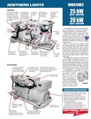
Figure 4: Lugger Main Instrument Control Panel<br />
1. TACHOMETER<br />
The tachometer shows the engine speed in revolutions<br />
per minute. (RPM). Numbers are multiples of 100.<br />
2. HOUR METER<br />
Keeps track of the engine running time.<br />
3. D.C. VOLTMETER<br />
When the engine is stopped, the voltmeter shows the<br />
condition of the battery. When the engine is running,<br />
it indicates the voltage output of the alternator.<br />
4. KEY SWITCH<br />
Turning the key clockwise to the fi rst position will<br />
switch on the current. Continue turning the key<br />
clockwise to preheat the engine, then again to start the<br />
engine. When the engine starts, immediately turn the<br />
key back to the fi rst position while the engine is running.<br />
The key must be kept in the “on” or fi rst position<br />
while the engine is running. Turn the key counter<br />
clockwise as far as possible to stop the engine.<br />
Note: Optional fl ybridge panels have engine start switches<br />
instead of key switches.<br />
5. COVER<br />
(Stop button not used <strong>for</strong> this application.)<br />
9<br />
Added page 1/15/10<br />
8<br />
7<br />
1<br />
6<br />
<strong>OL844</strong> 03/10<br />
5<br />
5<br />
2<br />
6. INSTRUMENT PANEL LIGHTING<br />
The switch turns on the instrument panel lights.<br />
7. OIL PRESSURE FAULT LIGHT<br />
Indicates low oil pressure. Activates in conjunction<br />
with alarm horn.<br />
8. ENGINE TEMPERATURE FAULT LIGHT<br />
Indicates engine is over-heating. Activates in<br />
conjunction with alarm horn.<br />
9. ALARM HORN<br />
Shut down engine if possible and investigate<br />
immediately.<br />
10. WIRE HARNESS<br />
Instrument Panel<br />
11. COOLANT TEMPERATURE GAUGE<br />
Water temperature gauge shows the temperature of the<br />
engine coolant. If the gauge registers over 200 0 F or<br />
drops below 140 0 F, stop the engine and investigate.<br />
12. OIL PRESSURE GAUGE<br />
Shows the oil pressure in the engine lubricating system.<br />
If the pressure drops below 15 PSI at a speed higher<br />
than idling, stop the engine immediately.<br />
3<br />
4
Operating Procedures<br />
BEFORE STARTING<br />
1. Check the water level by removing the pressure<br />
cap from the expansion tank. In order to give the<br />
cooling water room to expand, the level should be<br />
about 1 in. (2.5 cm) below the fi ller cap sealing<br />
surface when the engine is cold.<br />
CAUTION: Use protective clothing and open<br />
the fi ller cap carefully when the engine is warm<br />
to prevent burns.<br />
2. Check the oil level in the crankcase with<br />
the dipstick. The oil level should be between the<br />
“waffl ed area” and the “Add”. Never allow the<br />
level to go below the “Add”. Do not fi ll above the<br />
crosshatch pattern. Oil levels within the crosshatch<br />
are considered in the acceptable operating range.<br />
Always add the same viscosity of oil as is already in<br />
the crankcase (see Service Point #1).<br />
3. Check the fuel tank level and open any fuel valves.<br />
4. Check the oil level in the reverse gear. Methods<br />
may vary from gear to gear. See your Gear Owner's<br />
Manual.<br />
5. Close the seacock, check and clean the strainer and<br />
reopen the seacock.<br />
6. Place the battery switch in the ON position.<br />
Revised page 1/14/10<br />
NOTE: The battery switch must always be kept ON<br />
while the engine is running. If the switch is turned<br />
OFF while the engine is running, the battery charging<br />
regulator could be ruined.<br />
Starting<br />
1. Put the gear control in the neutral position.<br />
2. Move the throttle control to the idle position.<br />
3. Turn the key switch to the fi rst position. Check the<br />
voltage meter to see the condition of the batteries.<br />
For starting, the voltmeter should not read below 12<br />
volts (24 volts <strong>for</strong> 24 volt systems).<br />
4. Turn the key to the starting position and as soon as<br />
the engine starts, release the key. Move the throttle<br />
up until the engine is running at approximately 1000<br />
RPM.<br />
5. Do not crank the starter <strong>for</strong> more than 15 seconds<br />
consecutively. If the engne fails to start with the fi rst<br />
attempt, be sure that the starter has stopped completely<br />
be<strong>for</strong>e re-engaging.<br />
NOTE: Never race a cold engine. Operate at 1000<br />
RPM <strong>for</strong> a 3 to 5 minute warm-up period.<br />
<strong>OL844</strong> 03/10<br />
6<br />
Operating<br />
1. Check oil pressure as soon as the engine has started.<br />
Oil pressure should be above 15 PSI. The engine<br />
must never be run if the oil pressure is below 15 PSI.<br />
2. Check the voltmeter. It should read 13 to 14 volts<br />
(26-28 volts, 24 volt systems) at 60°F (16°C).<br />
3. Water temperature should not rise over 200°F (94°C).<br />
If it does, shut down the engine and investigate the<br />
cause of overheating.<br />
4. Do not exceed 800 RPM when shifting marine gear.<br />
Repeated shifts at higher engine speeds can damage<br />
the reverse gear.<br />
5. Low idle is 800 RPM. Maximum working engine<br />
speed is: 2800 RPM <strong>for</strong> 40 Hp.6. If the proper<br />
propeller is used, the engine should reach its appropriate<br />
maximum RPMs at full throttle. If the maximum<br />
rated RPMs <strong>for</strong> your engine application is exceeded<br />
at full throttle, then your propeller is too small. If<br />
you cannot reach your maximum rated RPMs at full<br />
throttle, either your propeller is too large or bottom<br />
growth is slowing the boat.<br />
7. To establish Maximum Cruising RPM: Establish the<br />
RPM at full throttle and subtract 200-300 RPM. This<br />
will promote engine life and reduce fuel consumption.<br />
Shutdown<br />
1. Run engine three to fi ve minutes in neutral at 1000<br />
RPM, <strong>for</strong> cool down period.<br />
2. Return engine to low idle.<br />
3. Turn the key switch counterclockwise as far as possible<br />
to stop the engine.<br />
4. Close the sea cock and fuel valves and put the battery<br />
switch in OFF position.<br />
NOTE: Do not turn the battery switch to OFF while the<br />
engine is running.<br />
ALARMS<br />
1. Your unit is fi tted with a warning system to indicate<br />
high water temperature or low oil pressure.<br />
Propulsion engines have warning horns to sound and<br />
warn you of a problem. Remember- when the engine<br />
is not running the horn will sound when the key is in<br />
the "ON" position because there is no oil pressure.
NOTE: Do not rely on your warning or shutdown system<br />
to the exclusion of careful gauge monitoring. Watching<br />
your gauges can prevent damage to the unit and<br />
dangerous power losses.<br />
2. Do the following when your shutdown system is activated:<br />
a. Check the temperature gauge. If the temperature is<br />
above 205°F (97°C), shut off the engine immediately.<br />
b. Use the Trouble Shooting Guide on pages 18- 19<br />
to isolate the cause of the overheat.<br />
CAUTION: Do not remove the water fi ll cap of an<br />
overheated engine. Escaping high temperature<br />
steam can cause severe burns. Allow the engine<br />
to cool and then remove the cap slowly, using<br />
protective clothing.<br />
c. Make repairs and restart after the temperature<br />
gauge registers below 180°F (83°C).<br />
d. Watch the temperature gauge regularly and turn<br />
off the unit if the temperature rises above 200°F<br />
(94°C). Repeat the troubleshooting process.<br />
3. If the shutdown is activated and the temperature gauge<br />
shows temperature within normal temperature range:<br />
a. Check the engine crankcase oil level.<br />
b. If the oil level is low, fi ll with recommended lubricating<br />
oil and restart. Watch the oil pressure gauge carefully<br />
and shut off the engine if it does not show a normal<br />
reading after a few seconds of operation.<br />
c. If the oil level is normal, DO NOT restart the<br />
engine. Call your <strong>Northern</strong> <strong>Lights</strong> or Lugger<br />
dealer <strong>for</strong> assistance.<br />
BREAK-IN PERIOD<br />
1. Your engine is ready to be put into service. However,<br />
the fi rst 100 hours on a new or reconditioned engine<br />
are critical to its life and per<strong>for</strong>mance. This is<br />
especially true of an engine that runs at a constant<br />
speed such as a propulsion engine does.<br />
2. Operate with an averager of 75% load on your engine<br />
<strong>for</strong> the fi rst 100 hours. Maintain no less than a 50%<br />
load to ensure proper seating of the piston rings.<br />
<strong>OL844</strong> 03/10<br />
7<br />
Operating Procedures<br />
3. Oil consumption is greater during break-in as<br />
piston rings take time to seat.<br />
4. Your engine comes equipped with break-in oil.<br />
Change engine oil and fi lter at 50 hours using<br />
API Service Category CC, CD, or CE break-in<br />
oil. Change the oil and fi lter again at 100 hours.<br />
(Consult the lubricants section <strong>for</strong> oil<br />
recommendations.)<br />
5. Frequently check the engine temperature and oil<br />
pressure gauges.<br />
OPERATING INSTRUCTIONS<br />
Never run full speed <strong>for</strong> more than 5 minutes<br />
during the fi rst 50 hours. Run engine at 50%<br />
to 75% of maximum working speed <strong>for</strong> the fi rst<br />
20 hours with as little idling time as possible.<br />
Extended idling can inhibit ring seating, causing<br />
cylinder walls to glaze.
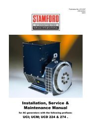
Servicing Schedule Chart<br />
The Servicing Schedule Chart below shows the service schedule required <strong>for</strong> proper maintenance of your marine engine<br />
or generator set. More detailed coverage of each Service Point (SP) is listed on the page noted in the ‘page’ column.<br />
DAILY:<br />
SP1 Check oil level in engine<br />
SP7 Check primary fuel fi lter<br />
SP14 Check cooling water level<br />
SP24 Check sea water strainer<br />
AFTER FIRST 50 HOURS:<br />
SP2 Change engine oil<br />
SP3 Change lube oil fi lter<br />
EVERY 50 HOURS:<br />
SP20 Check electrolyte in batteries<br />
FIRST 100 HOURS:<br />
SP2 Change engine oil<br />
SP3 Change lube oil fi lter<br />
EVERY 200 HOURS:<br />
SP2 Change engine oil<br />
SP3 Change lube oil fi lter<br />
SP4 Check air cleaner<br />
SP8 Change primary fuel fi lter element<br />
1) Per<strong>for</strong>m all maintenance once a year even if hour level has not been reached.<br />
2) Consult manufacturer's maintenance schedule, note on chart.<br />
3) Whenever necessary.<br />
<strong>OL844</strong> 03/10<br />
8<br />
SP9 Change secondary fuel fi lter<br />
SP12 Check condition of exhaust elbow<br />
SP18 Check zinc electrodes<br />
EVERY 600 HOURS / YEARLY:<br />
SP4 Replace air cleaner<br />
SP5 Check V-belt condition<br />
SP6 Check valve clearances<br />
SP10 Check injectors<br />
SP15 Check and fl ush cooling system<br />
SP19 Change impeller in raw water pump<br />
SP21 Check the state of the charge of the batteries<br />
EVERY 2500 HOURS:<br />
SP16 Check and clean heat exchanger<br />
SP17 Check and clean gear oil cooler<br />
SERVICE 50 200 600 2500<br />
POINT PAGE OPERATION DAILY Hours Hours Hours Hours<br />
SP1<br />
SP2<br />
SP3<br />
SP4<br />
SP5<br />
SP6<br />
10<br />
10<br />
10<br />
10<br />
11<br />
ENGINE:<br />
Check oil level<br />
Change engine oil<br />
Change lube oil fi lters<br />
Check (replace) air cleaner<br />
Check belt condition<br />
Check valve clearances<br />
1)<br />
1)<br />
1) 3)<br />
1)<br />
1)<br />
•<br />
•<br />
•<br />
• •<br />
•<br />
•<br />
FUEL SYSTEM:<br />
SP7 12 Check primary fi lter (Racor) 2) •<br />
SP8 12 Change primary fi lter element (Racor) 2) 3) •<br />
SP9 12 Change secondary fuel fi lter 1) 3) •<br />
SP10 Check injectors 1) •<br />
SP12 Check condition of exhaust elbow 4) •<br />
COOLING SYSTEM:<br />
SP14 15 Check cooling water level •<br />
SP15 15 Check and fl ush cooling system 1) •<br />
SP16 15 Check and clean heat exchanger 1) •<br />
SP17 Check and clean gear oil cooler 1) •<br />
SP18 15 Check zinc electrodes 1) 3) •<br />
SP19 16 Change impeller in raw water pump 1) 3) •<br />
SP24 Check sea water strainer •<br />
ELECTRICAL SYSTEM:<br />
SP20 17 Check electrolyte level in batteries 1) 3) •<br />
SP21 17 Check condition of batteries with hydrometer 1) •<br />
OUT OF SERVICE:<br />
SP22 17 Winterizing or out-of-service 3)
Service<br />
Point<br />
SP20 Check electrolyte<br />
in batteries<br />
SP2 Change engine oil<br />
OPERATION<br />
SP3 Change lubricating oil fi lters<br />
SP4 Check air cleaner<br />
SP7 Change primary fuel fi lter element<br />
SP9 Change secondary fuel fi lter<br />
SP12 Check turbocharger air, oil & cooling lines <strong>for</strong> leakage<br />
SP18 Check zinc electrodes<br />
SP4 Replace air cleaner<br />
SP5 Check belt condition<br />
SP6 Check valve clearances<br />
SP10 Check injectors<br />
SP13 Check turbocharger boost pressure<br />
SP15 Check and fl ush cooling system<br />
SP19 Change impeller in raw water pump<br />
SP21 Check state of charge of batteries<br />
SP16 Check and clean heat exchanger<br />
SP17 Check and clean reverse gear oil cooler<br />
SP23 Check crankshaft damper<br />
50 HOURS<br />
200 HOURS<br />
600 HOURS<br />
2500 HOURS<br />
<strong>OL844</strong> 03/10<br />
9<br />
HOURS/DATE<br />
Service Record
Servicing<br />
LUBRICATION<br />
Break-in oil<br />
1. Use one of the following during the fi rst 100 hours<br />
of operation:<br />
a. John Deere Engine Break-In Oil<br />
b. API Service CC, CD oil<br />
c. ACEA Specifi cation E1<br />
2. Do not use John Deere PLUS-50 oil or engine oils<br />
meeting API CF-4, API CG-4, API CH-4, API<br />
CI-4, ACEA E2, ACEA E3, ACEA E4, or ACEA<br />
E5 per<strong>for</strong>mance levels during the fi rst 100 hours of<br />
operation of a new or rebuilt engine. These oils will<br />
not allow the engine to break-in properly.<br />
Lubrication - General<br />
1. Use only clean, high quality lubricants stored in<br />
clean containers in a protected area.<br />
2. These oils are acceptable after the fi rst 100 hours:<br />
a. API Service CH-4, CI-4 multi-viscosity oils.<br />
b. API Service CD/CG-4/CF-4 multi-viscosity oils.<br />
c. ACEA Specifi cation E3<br />
d. ACEA Specifi cation E4/ E5<br />
3. Use the proper weight oil <strong>for</strong> your average operation<br />
temperature.<br />
Air Single Multi<br />
Temperature Viscosity Viscosity<br />
Above 32°F<br />
(0°C)<br />
-10°F to 32°F<br />
(-23°C to 0°C)<br />
Below -10°F<br />
(-23°C)<br />
SAE-30W SAE15-40W<br />
SAE-10W SAE10-30W<br />
SAE-5W SAE5-20W<br />
4. Some increase in oil consumption may be expected<br />
when SAE 5W and SAE 5-20W oils are used. Check<br />
oil level frequently.<br />
5. Never put additives or fl ushing oil in crankcase.<br />
SP1. CHECK ENGINE OIL LEVEL<br />
1. Check the oil level in the crankcase, with the oil<br />
dipstick, daily.<br />
2. The oil level must be between the “Waffl ed area”<br />
and the “Add”. Never allow the level to go below the<br />
“Add”.<br />
3. Always add the same viscosity of oil as is already in<br />
the crankcase.<br />
SP2. OIL CHANGES<br />
1. Using the oil recommended above, change the engine oil<br />
and fi lter after the fi rst 50 hours of operation, and every 200<br />
hours thereafter.<br />
2. During intermittent cold weather operation, change oil every<br />
100 hours or six weeks, whichever comes fi rst.<br />
3. Change oil at any seasonal change in temperature when a<br />
new viscosity of oil is required.<br />
Marine Generator Sets:<br />
a. Remove plug from outlet in base frame. Screw in<br />
owner-supplied drain hose.<br />
b. Open valve at oil pan outlet. After oil has been<br />
drained into suitable container, close valve, remove<br />
drain hose and replace plug in base frame outlet.<br />
c. Refi ll engine with recommended oil.<br />
4. Engine Lube Oil Capacity:<br />
SP3. CHANGING OIL FILTER<br />
1. Change the lube oil fi lter every 200 hours.<br />
2. Use a fi lter wrench to remove old fi lter. Dispose of<br />
fi lter in approved manner.<br />
3. Make sure the gasket from the old fi lter is removed<br />
and discarded.<br />
4. Lubricate the rubber gasket on the new fi lter and screw<br />
it on nipple until gasket meet the sealing surface.<br />
5. Using hands only, no wrench, tighten fi lter one-half turn<br />
farther. Overtightening can do damage to fi lter housing.<br />
6. Fill engine with recommended oil. Start engine and<br />
check <strong>for</strong> leakage. Stop engine and check oil level.<br />
Add additional oil if necessary.<br />
SP4. AIR CLEANER<br />
1. Inspect air cleaner every 100 hours. Replace fi lter<br />
every 600 hours, or yearly, whichever comes fi rst.<br />
2. Clean the rubber tube at the cleaner. Loosen the hose<br />
clamp and the attaching strip <strong>for</strong> the cleaner.<br />
3. Make sure the rubber tube is in good condition and<br />
that new fi lter is absolutely clean and installed properly.<br />
4. Start the engine and check <strong>for</strong> leaks.<br />
<strong>OL844</strong> 03/10<br />
10<br />
844 2.1 gallons 8.2 liters<br />
NOTE: Make absolutely sure no impurities enter<br />
the engine while changing the element. Do not<br />
run the engine with the air cleaner removed.
SP6. VALVE CLEARANCES<br />
1. Adjust valve clearance after the fi rst 50 hours of<br />
operation and every 600 hours thereafter.<br />
2. Engine should be cold and NOT running.<br />
3. Watch the valves while turning the engine over by<br />
hand. Turn until the inlet valve starts to open and<br />
the exhaust valve starts to close (the valves are<br />
rocking). Then turn the crankshaft one more full<br />
turn and adjust the clearance on both valves <strong>for</strong> this<br />
cylinder.<br />
Flywheel<br />
Ex In Ex In Ex In Ex In<br />
Figure 3: 844 Valve sequence<br />
4. Loosen the lock nut and adjust the clearance between<br />
the rocker arm and valve guide of both the intake<br />
and exhaust valves with the adjustment screw<br />
(Figure 4). Clearance on both intake and exhaust<br />
valves should be 0.008 inches (0.2 mm).<br />
5. Repeat steps 3 and 4 <strong>for</strong> each cylinder. Each set of<br />
valves must be adjusted individually.<br />
6. Replace the rocker arm cover. Tighten cover nuts to<br />
5 - 8 ft/lbs (0.8 - 2.3 kg/m).<br />
Figure 4: Valve adjustment<br />
<strong>OL844</strong> 03/10<br />
11<br />
Servicing<br />
FUELS - GENERAL<br />
1. Use only clean, high quality fuels of the following<br />
specifi cations, as defi ned by ASTM designation D975<br />
<strong>for</strong> diesel fuels:<br />
a. Use grade no. 2 diesel at ambient temperatures<br />
above freezing 30°F (0°C).<br />
b. Use grade No.1 at ambient temperatures below<br />
freezing and <strong>for</strong> all temperatures at an altitude of<br />
above 5,500 ft. (1500 meters).<br />
2. Sulphur content should not exceed 0.5% (preferably<br />
less than 0.5%).<br />
3. The cetane number should be a minimum of 45.<br />
4. DO NOT use these unsuitable grades of fuel:<br />
a. Domestic heating oils, all types.<br />
b. Class B engine.<br />
c. Class D domestic fuels.<br />
d. Class E, F, G or H industrial or marine fuels.<br />
e. ASTM-D975-60T No. 4-D and higher number<br />
fuels.<br />
f. JP4<br />
5. Storing fuel:<br />
a. Keep dirt, scale, water and other <strong>for</strong>eign matter<br />
out of fuel.<br />
b. Avoid storing fuel <strong>for</strong> long periods of time.<br />
c. Fill the fuel tank at the end of each day's<br />
operation. This will reduce condensation.
Servicing<br />
SP7 - 9. FUEL FILTERS<br />
1. Your engine or generator set should have a primary<br />
fuel fi lter installed. We recommend the Racor brand<br />
of fuel fi lter - water separators.<br />
a. Check the primary fuel fi lter daily as recommended<br />
by the fi lter manufacturer. Empty the collection<br />
bowl as necessary.<br />
b. Change the element every 200 hours or whenever<br />
necessary.<br />
c. If the bowl fi lls with water, change the primary<br />
and secondary elements immediately.<br />
2. Change secondary fuel fi lter every 200 hours.<br />
NOTE: The fuel fi lter on the engine is considered the<br />
“secondary fuel fi lter”.<br />
a. Turn off the fuel.<br />
b. Be sure area around fuel fi lter assembly is clean.<br />
c. Remove the cap from the fuel fi lter housing. A<br />
wrench or pliers may be needed.<br />
Figure 5: Primary Fuel fi lter<br />
d. Operate the hand primer until the fuel fi lter pops<br />
up. If this does not happen, use a small screw<br />
driver and carefully pry under the fi lter fl ange.<br />
e. Install new fi lter cartridge, do not reuse the old<br />
one. A stalled engine could result from air<br />
bubbles in the old fi lter cartridge causing fuel to<br />
overfl ow from the housing.<br />
<strong>OL844</strong> 03/10<br />
12<br />
f. Ensure that the fuel level is between the minimum<br />
and maximum marks on the center tube in the<br />
middle of the fi lter housing. If the fuel is below the<br />
minimum level, use the hand primer to add more<br />
fuel. Fuel level below the minimum could cause<br />
the engine to stall because of trapped air in the new<br />
fi lter. Fuel level above the maximum could cause<br />
the fuel to overfl ow from the fi lter housing when<br />
the fuel fi lter is installed.<br />
g. Install new fi lter, replace cap, restart engine and<br />
run <strong>for</strong> fi ve minutes minimum.<br />
h. Remove and clean the water separator bowl, by<br />
fi rst disconnecting the wiring connector from the<br />
water-in-fuel sensor.<br />
i. Drain the fuel from the separator bowl. Use a strap<br />
wrench close to the top of the bowl, while gripping<br />
bowl and twisting it with the other hand to remove<br />
it. Clean and dry the bowl. Reinstall and hand<br />
tighten. Reconnect sensor.<br />
BLEEDING THE FUEL SYSTEM<br />
CAUTION: Escaping diesel fuel under pressure<br />
can penetrate the skin, causing serious personal<br />
injury. Be<strong>for</strong>e disconnecting lines be sure to relieve<br />
all pressure. Be<strong>for</strong>e applying pressure to the system<br />
be sure all connections are tight and the lines, pipes<br />
and hoses are not damaged. Fuel escaping from a<br />
very small hole can be almost invisible. Use a piece<br />
of cardboard or wood rather than the hands to search<br />
<strong>for</strong> suspected leaks. If injured by escaping fuel, see<br />
a doctor at once. Serious infection or reaction can<br />
develop if proper medical treatment is not<br />
administered immediately.<br />
1. The fuel system is self-bleeding. However, any<br />
system may need manual bleeding when:<br />
a. A new fuel fi lter is installed;<br />
b. The engine has run out of fuel;<br />
c. The fuel lines, injection pump, or any other fuel<br />
system component has been removed and<br />
installed.<br />
2. Loosen bleed bolt “A” (fi gure 6) on top of the fi lter.<br />
Pump hand primer “B” on fuel lift pump until pure<br />
fuel (no bubbles) escapes from bleed bolt “A”.<br />
Tighten bleed screw “A”.<br />
3. Loosen bleed screw “C”. Pump hand primer “B” until<br />
pure fuel (no bubbles) escapes. Then tighten bleed<br />
screw “C”.
4. If the engine does not start after the above bleeding<br />
process, loosen a fuel line at the injector while<br />
cranking the engine with the starter motor until pure<br />
fuel escapes. Then tighten the connection. Do each<br />
line one-at-a time.<br />
5. After the engine has started, use a piece of cardboard<br />
to look <strong>for</strong> fuel leaks.<br />
Figure 6<br />
COOLING REQUIREMENTS<br />
1. To meet cooling system protection requirements, the<br />
coolant solution must consist of:<br />
a. Quality water<br />
b. Ethylene glycol concentrate (EGC ) commonly<br />
known as antifreeze.<br />
c. Supplemental coolant additives (SCA's).<br />
2. A coolant solution of ethylene glycol concentrate<br />
(EGC-antifreeze), quality water and supplemental<br />
coolant additives (SCA's) MUST be used YEAR<br />
ROUND to protect against freezing, boil-over, liner<br />
erosion or pitting and to provide a stable, noncorrosive<br />
environment <strong>for</strong> cooling system components.<br />
3. Ethylene glycol coolant concentrate (antifreeze)<br />
normally DOES NOT contain the SCA chemical<br />
inhibitors needed to control liner pitting or erosion,<br />
rust, scale, and acidity.<br />
<strong>OL844</strong> 03/10<br />
13<br />
Servicing<br />
WATER QUALITY<br />
1. Distilled, deionized, soft water is preferred <strong>for</strong> use in<br />
cooling systems. Bottled distilled water from a food<br />
store or water supplier is recommended. Tap water<br />
often has a high mineral content. Tap water should<br />
NEVER be put in a cooling system unless fi rst tested<br />
by a water quality laboratory.<br />
2. Here are acceptable water quality specifi cations:<br />
Parts Grains<br />
Contaminates per Million per Gallon<br />
Maximum Chlorides 40 2.5<br />
Maximum Sulfates 100 5.9<br />
Maximum Dissolved Solids 340 20.0<br />
Maximum Total Hardness 170 10.0<br />
PH Level 5.5 to 9.0
Servicing<br />
3. If chlorides, sulfates or total dissolved solids are<br />
higher than the above given specifi cation, the water<br />
must be distilled, demineralized, or deionized be<strong>for</strong>e<br />
it is used in a cooling system.<br />
4. If total hardness is higher than 170 ppm and all other<br />
parameters are within the given specifi cations, the<br />
water must be softened be<strong>for</strong>e it is used to make<br />
coolant solution.<br />
EGC: ETHYLENE GLYCOL CONCENTRATE<br />
(ANTIFREEZE)<br />
CAUTION: EGC (Antifreeze) is fl ammable.<br />
Keep it away from any open fl ame. Avoid contact<br />
with eyes. Avoid contact with skin. Do not take internally.<br />
In case of contact, immediately wash skin with<br />
soap and water. For eyes, fl ush with large amounts<br />
of water <strong>for</strong> at least 15 minutes. Call a physician.<br />
KEEP OUT OF REACH OF CHILDREN. Follow all<br />
warnings on the container.<br />
1. Ethylene glycol coolant concentrate is commonly<br />
mixed with water to produce an engine coolant with<br />
a low freeze point and high boiling point.<br />
2. A low silicate <strong>for</strong>m of ethylene glycol coolant is<br />
recommended <strong>for</strong> all diesel engines.<br />
3. Use an ethylene glycol coolant concentrate<br />
meeting ASTM D 6210, D4985P, and D5345.<br />
4. This product is concentrated and should be mixed<br />
to the following specifi cation.<br />
5. If additional coolant solution needs to be added<br />
to the engine due to leaks or loss, the glycol<br />
concentration should be checked with a hydrometer<br />
to assure that the desired freeze point is maintained.<br />
Distilled EGC % Freeze Boiling<br />
Water % Antifreeze Point Point<br />
Optimum 50% 50%<br />
Minimum 60% 40%<br />
Maximum 40% 60%<br />
-37°C +109°C<br />
-34°F +226°F<br />
-24°C +106°C<br />
-12°F +222°F<br />
-52°C +111°C<br />
-62°F +232°F<br />
<strong>OL844</strong> 03/10<br />
14<br />
IMPORTANT<br />
1. DO NOT use methyl alcohol or methoxy propanol<br />
base EGC. These concentrates are not compatible<br />
with chemicals used in supplemental coolant additives.<br />
Damage can occur to rubber seals on cylinder<br />
liners which are in contact with coolant.<br />
2. DO NOT use an EGC containing sealer or stop-leak<br />
additives.<br />
3. DO NOT use EGC containing more than 0.1%<br />
anhydrous metasilicate. This type of concentrate,<br />
which is intended <strong>for</strong> use in aluminum engines, may<br />
cause a gel-like deposit to <strong>for</strong>m that reduces heat<br />
transfer and coolant fl ow. Check container label or<br />
consult with supplier.
SP14. CHECKING COOLANT LEVEL<br />
CAUTION: The cooling water in the engine<br />
reaches extremely high temperatures. You must<br />
use extreme caution when working on hot engines<br />
to avoid burns. Allow the engine to cool be<strong>for</strong>e<br />
working on the cooling system. Open the fi ller cap<br />
carefully, using protective clothing when the engine<br />
is warm.<br />
1. Check the coolant level each day be<strong>for</strong>e starting the<br />
engine.<br />
2. Remove the pressure cap from the expansion tank<br />
and check water level. In order to give the coolant<br />
an opportunity to expand, the level should be about<br />
1 in. (2.5 cm) below the fi ller cap sealing surface<br />
when the engine is cold.<br />
2. The pressure valve in the fi ller cap releases when the<br />
pressure is approximately 7 PSI (0.5 bar). Use a cap<br />
pressure tester to check cap if you suspect it is faulty.<br />
4. The makeup coolant, added to compensate <strong>for</strong> loss<br />
or leaks, must meet engine coolant requirements<br />
outlined in previous section.<br />
SP15. FLUSHING THE COOLING SYSTEM<br />
CAUTION: The cooling water in the engine reaches<br />
extremely high temperatures. You must use extreme<br />
caution when working on hot engines to avoid burns.<br />
Allow the engine to cool be<strong>for</strong>e working on the<br />
cooling system. Open the fi ller cap carefully, using<br />
protective clothing when the engine is warm.<br />
<strong>OL844</strong> 03/10<br />
15<br />
1. Flush the cooling system and check <strong>for</strong> leaks and<br />
blockage every 600 hours, or yearly. The engine<br />
must be stopped and cold.<br />
2. Close the seacock.<br />
3. Remove the pressure cap from the expansion tank<br />
with caution. If applicable, open the cooling system<br />
air vent on top of turbocharger.<br />
4. Open the drains on the exhaust manifold and engine<br />
block. Drain the fresh water system (see Component<br />
Locations, page 4).<br />
5. For vessels with keel cooling, the vessel must be out<br />
of the water to allow draining of the keel cooler.<br />
6. With drains open, pour clean water into the expansion<br />
tank. When the water from drain is clear and free from<br />
discoloration and sediment, close that drain. When all<br />
drains are closed, fl ushing is complete.<br />
7. Fill the fresh water system by pouring the<br />
recommended coolant mixture as described in previous<br />
sections.<br />
8. Open the seacock.<br />
9. Start the engine. Check hoses and connections and<br />
repair any leakage.<br />
SP16. HEAT EXCHANGER CLEANING<br />
1. Clean the heat exchanger core once a year or after<br />
2400 hours of operation.<br />
2. Drain expansion tank and heat exchanger.<br />
3. Remove heat exchanger end covers and remove<br />
core.<br />
4. Clean the inside of exchanger core tubes using a<br />
metal rod. Flush, inspect and clean again if<br />
necessary.<br />
5. Reassemble. Fill the cooling system, start the engine<br />
and check <strong>for</strong> leaks.<br />
SP18. ZINC ANODES<br />
Servicing<br />
1. Zincs are installed in the cooling system to protect<br />
your engine from electrolysis. Check them faithfully<br />
every 200 hours. If you are in warm salt water or<br />
where electrolysis is a known problem, check them<br />
more often.
Servicing<br />
SP19. RAW WATER PUMP<br />
Heat exchanged cooled engines only.<br />
1. Change the sea water pump impeller as needed.<br />
2. Remove the pump end cover. Remove impeller with<br />
water pump pliers. Be sure you remove all pieces of<br />
a failed impeller.<br />
3. Clean the inside of the housing.<br />
4. Press in the new impeller and place the sealing<br />
washer in the outer end of the impeller center if this<br />
has not already been done.<br />
5. Replace the cover using a new gasket.<br />
Note: Make sure there is always an extra impeller<br />
and cover gasket in reserve and on-board.<br />
DRIVEN EQUIPMENT<br />
Gears and PTO's<br />
1. Manufacturer's service recommendations vary. See<br />
your Owner's Manual <strong>for</strong> service in<strong>for</strong>mation. If you<br />
do not have a manual, see your local dealer <strong>for</strong> the<br />
equipment in question.<br />
<strong>OL844</strong> 03/10<br />
16<br />
NOTE: Some PTO and marine gears have<br />
rigid lubrication requirements. Follow service recommendations<br />
closely.<br />
ELECTRICAL SYSTEM - GENERAL<br />
1. Never switch battery switch off or break the circuit<br />
between the alternator and batteries while the engine<br />
is running. Regulator damage can result.<br />
2. DO NOT reverse the polarity of battery cables when<br />
installing the battery.<br />
3. When welding on the unit, disconnect the regulator<br />
and battery. Isolate the leads.<br />
4. Disconnect battery cables when servicing the DC<br />
alternator.<br />
5. Never test with a screwdriver, etc., against any terminal<br />
to see if it emits sparks.<br />
6. A DC circuit breaker protects your control panel and<br />
wiring harness.
BOOSTER BATTERIES<br />
CAUTION: Battery Gas Can Explode. Keep all<br />
fl ames and sparks away from batteries.<br />
1. Be<strong>for</strong>e changing or using booster batteries, check<br />
battery electrolyte level. Add distilled water.<br />
2. Booster and main batteries must have the same voltage<br />
rating.<br />
3. First, connect positive (+) terminal of booster<br />
battery to positive (+) terminal of main battery.<br />
Figure 7: Booster Battery Connections<br />
4. Then, connect negative (-) terminal of booster battery<br />
to ground on the engine block (see Figure 7).<br />
5. Remove booster battery after starting engine.<br />
6. Sealed batteries: see manufacturer charging and<br />
booster instructions.<br />
SP20 - 21. BATTERY CARE - LEAD/ACID TYPE<br />
BATTERIES<br />
1. Check electrolyte level every 50 hours<br />
or once per month. Add distilled water to<br />
manufacturer's recommended level.<br />
2. Batteries, cables and cable terminals should be<br />
checked and cleaned every 100 hours. Clean corrosion<br />
with a water and baking soda solution. Flush<br />
with clean water. Tighten terminals and<br />
grease them to inhibit corrosion.<br />
3. Check the battery condition with a hydrometer<br />
every 750 hours.<br />
<strong>OL844</strong> 03/10<br />
17<br />
SP22. WINTERIZING, OUT-OF-SERVICE<br />
Servicing<br />
The following long term storage preparation guides<br />
are good <strong>for</strong> storage up to one year, after that the engine<br />
should be started, warmed up, and prepared again <strong>for</strong><br />
long term storage.<br />
1. Change oil and replace fi lter. Used oil will not give<br />
adequate protection.<br />
2. Service the air cleaner.<br />
3. For storage less than a year it is not necessary to<br />
drain and fl ush the cooling system. For a year<br />
or more of storage the cooling system should be<br />
drained, fl ushed and refi lled with appropriate coolant.<br />
4. Remove the fan and alternator belts, optional.<br />
5. Remove and clean the batteries. Store them in a cool<br />
dry place and be sure they are fully charged.<br />
6. Disengage the clutch to engine drivelines.<br />
7. Clean the exterior of the engine with salt-free water<br />
and touch up painted surfaces with good paint.<br />
8. Coat all exposed machined metal surfaces with<br />
grease or corrosion inhibitors if they cannot be<br />
painted.<br />
9. Seal all openings with plastic bags and tape.<br />
10. Store the engine in a dry protected place. If the<br />
engine must be outside, cover with waterproof<br />
canvas or other protective material and use strong<br />
waterproof tape.
Troubleshooting<br />
If you cannot correct problems with these procedures, see your Lugger or <strong>Northern</strong> <strong>Lights</strong> dealer.<br />
� Engine Will Not Crank<br />
Weak battery:<br />
• Replace battery.<br />
Corroded or loose battery connections:<br />
• Clean battery terminals and connections.<br />
Defective main switch or start safety switch:<br />
• Repair switch as required.<br />
Starter/solenoid defective:<br />
• Replace starter or solenoid.<br />
� Hard to Start or Will Not Start<br />
Poor fuel quality:<br />
• Drain fuel and replace with proper grade fuel.<br />
Slow cranking speed:<br />
• Check <strong>for</strong> problems in the charging or starting<br />
system.<br />
� Engine Misfi ring or Runs Irregularly<br />
Basic engine problem:<br />
• See your dealer.<br />
� Lack of Engine Power<br />
Poor fuel quality:<br />
• Drain fuel and replace correct grade fuel.<br />
Intake air restriction:<br />
• Service air cleaner.<br />
Clogged primary fuel fi lter:<br />
• Clean or replace fi lter element.<br />
Clogged secondary fuel fi lter element:<br />
• Replace secondary fi lter element.<br />
Crankcase oil too heavy:<br />
• Fill with oil of appropriate viscosity.<br />
� Low Oil Pressure<br />
Low crankcase oil level:<br />
• Fill crank case to proper level.<br />
Clogged oil cooler or fi lter:<br />
• Remove and inspect oil cooler. See your<br />
dealer.<br />
High oil temperature:<br />
• Remove and inspect oil cooler. See your<br />
dealer.<br />
Defective oil pump:<br />
• Remove and inspect oil pump. See your<br />
dealer.<br />
Oil pressure regulating valve failure:<br />
• Remove and inspect oil pressure regulating<br />
valve. See your dealer.<br />
Broken piston spray jet:<br />
• Replace piston spray jet. See your dealer.<br />
Clogged oil pump screen or cracked pick-up tube:<br />
• Remove oil pan and clean screen/ replace<br />
pick-up tube.<br />
Excessive main or connecting rod bearing clearance:<br />
• Determine bearing clearance. See your dealer.<br />
� High Oil Pressure<br />
Regulating valve not operating correctly:<br />
• Remove and inspect oil pressure regulating<br />
valve. See your dealer.<br />
Plugged piston spray jet:<br />
• Replace piston spray jet. See your dealer.<br />
Filter bypass valve stuck or damaged:<br />
• Remove and inspect fi lter bypass valve. See<br />
your dealer.<br />
� High Oil Consumption<br />
Crankcase oil too low viscosity:<br />
• Drain crankcase and refi ll with correct oil.<br />
Crankcase oil level too high:<br />
• Drain oil until level is correct.<br />
External oil leak:<br />
• Check <strong>for</strong> leaks in lines around gaskets and<br />
drain plug.<br />
Oil control rings worn or broken:<br />
• Replace piston rings. See your dealer.<br />
Scored cylinder liners or pistons:<br />
• Remove and inspect cylinders and liners;<br />
replace as required. See your dealer.<br />
Worn valve guides or stems:<br />
• Inspect and measure valve stems and valve<br />
guides; repair as required. See your dealer.<br />
Piston grooves worn:<br />
• Remove and inspect pistons. See your dealer.<br />
Piston rings sticking in ring grooves:<br />
• Remove and inspect pistons. See your dealer.<br />
Insuffi cient piston ring tension:<br />
• Remove and inspect pistons. See your dealer.<br />
Piston ring gaps not staggered:<br />
• Remove and inspect pistons. See your dealer.<br />
Front and/or rear crankshaft oil seal faulty:<br />
• Replace oil seals. See your dealer.<br />
� Excessive Fuel Consumption<br />
Intake air restriction:<br />
• Service air cleaner.<br />
Improper type of fuel:<br />
• Consult fuel supplier and use proper type of<br />
fuel <strong>for</strong> operating conditions.<br />
<strong>OL844</strong> 03/10<br />
18
If you cannot correct problems with these procedures, see your Lugger or <strong>Northern</strong> <strong>Lights</strong> dealer.<br />
Excessive Fuel Consumption (continued)<br />
Engine overloaded :<br />
• Reduce load on engine.<br />
Compression too low:<br />
• Determine cause of low compression and<br />
repair.<br />
Leaks in fuel supply:<br />
• Locate source of leak and repair as required.<br />
� Abnormal Engine Noise<br />
Worn main or connecting rod bearings:<br />
• Determine bearing clearance. See your dealer.<br />
Excessive crankshaft end play:<br />
• Check crankshaft end play. See your dealer.<br />
Loose main bearing caps:<br />
• Check bearing clearance, replace bearings and<br />
bearing cap screws as needed. See your<br />
dealer.<br />
Worn connecting rod bushings and piston pins:<br />
• Inspect piston pins and bushings. See your<br />
dealer.<br />
Scored pistons:<br />
• Inspect pistons. See your dealer.<br />
Worn timing gears or excessive back lash:<br />
• Check timing gear back lash. See your dealer.<br />
Excessive valve clearance:<br />
• Check and adjust valve clearance. See your<br />
dealer.<br />
Worn camshaft lobes:<br />
• Inspect camshaft. See your dealer.<br />
Worn rocker arm shafts:<br />
• Inspect rocker arm shafts. See your dealer.<br />
� Engine Emits Black or Gray Exhaust Smoke<br />
Clogged or dirty air cleaner:<br />
• Service air cleaner.<br />
Defective muffl er (back pressure too high):<br />
• Have dealer check back pressure.<br />
Improper fuel:<br />
• Use correct fuel <strong>for</strong> temperature.<br />
� Engine Emits White Smoke<br />
Engine compression too low:<br />
• Determine cause, see dealer.<br />
Defective thermostat (does not close):<br />
• Remove and check thermostats, replace if<br />
needed.<br />
Coolant entering combustion chamber, maybe a<br />
failed cylinder head gasket or cracked cylinder head:<br />
• Repair, see your dealer.<br />
<strong>OL844</strong> 03/10<br />
19<br />
Troubleshooting<br />
� Engine Emits White Smoke<br />
Water-to-air aftercooler fails:<br />
• Remove and inspect water-to-air aftercooler.<br />
See your dealer.<br />
� Engine Idles Poorly<br />
Improper type of fuel:<br />
• Replace with correct fuel grade.<br />
Air leak on suction side of air intake:<br />
• Check hose and pipe connections <strong>for</strong> tightness,<br />
repair as required.
<strong>L844D</strong> Data<br />
40 Hp<br />
Hp/ RPM 2800 RPM<br />
General In<strong>for</strong>mation<br />
Engine Type Lugger 4 cycle, swirl chamber diese<br />
Cylinders Inline 4<br />
Displacement 121in 3 (1.995 liters)<br />
Cycles 4<br />
Bore x Stroke 3.3 x 3.5 in (84 x 90 mm)<br />
Rotation (Facing Flywheel) counter-clockwise<br />
Compression Ratio 22:1<br />
Crankcase Capacity including Oil Filter 2.1 gal (8.2 liter)<br />
Aspiration Natural<br />
Flywheel Housing Size SAE 4<br />
Flywheel Drive Size C-107<br />
Rated Crankshaft Hp 1 40 Hp<br />
Rated Crankshaft kW 2 29.6 kW<br />
Dry Weight w/Heat Exchanger, Single Phase 873 lbs. (396 kg)<br />
Length 31.1 in (789 mm)<br />
Width 19.75 in (502 mm)<br />
Height 26.7 in (678 mm)<br />
Cooling System<br />
Approx. Coolant Cap. 1.4 gal (5.3 liter)<br />
Minimum Through Hull Diameter 3/4 in (20 mm)<br />
Sea Water Pump Inlet Hose ID 3/4 in (20 mm)<br />
Minimum Sea Water Discharge 3/4 in (20 mm)<br />
Heat Rejection to Jacket Coolant 1567 BTU/min<br />
Fresh Water Pump Cap. 20.1 gpm (76 lpm)<br />
Seawater Pump Cap. 14 gpm (53 lpm)<br />
Maximum Seawater Pump Suction Head 39 in (990 mm)<br />
Keel Cooler TurboTube Length 6 feet (1.8 M)<br />
Keel Cooler Head Diameter 1 in (25.4 mm)<br />
Keel Cooler Water Hose ID 1.25 in (31.5 mm)<br />
D.C. Electrical<br />
Minimum Battery Capacity 120 Amp Hour<br />
Battery Cable Size #1<br />
Starting Voltage, Negative Ground 12 Volt<br />
Air Intake and Exhaust<br />
Air Consumption 101 cfm (2.86 M 3 /m)<br />
Maximum Exhaust Backpressure 48 in (1219 mm) H 2 O<br />
Wet Exhaust Elbow OD 2 in (51 mm)<br />
Exhaust Gas Volume 238 cfm (6.7 M 3 /m)<br />
Exhaust Gas Temperature 1022° F (550° C)<br />
Fuel System<br />
Minimum Suction Line 5/16-.3125 in (7.9 mm)<br />
Minimum Return Line 5/16-.3125 in (7.9 mm)<br />
Maximum Fuel Pump Suction Head 39 in (990 mm)<br />
Specifi c Fuel Consumption at Max. Load .421 lbs/hp/hr<br />
Approximate Fuel Rate at Max. Load 2.37 US gph (8.9 lph)<br />
Maximum Engine Operating Angle<br />
Continuous Operation Front Down Rear Down<br />
(More than 2 minutes requires use of a remote expansion tank) 0° 0° - 10°<br />
Intermittent Operation (Sustained up to two minutes) 0° - 35° 0° - 35°<br />
1. Based on SAE J816b.<br />
2. Based on EN ISO 8665:2006.<br />
Revised page 1/14/10<br />
<strong>OL844</strong> 03/10<br />
20
<strong>OL844</strong> 03/10<br />
21<br />
Engine Wiring Diagram<br />
DC Wiring Diagram<br />
12 Volt Standard Ground<br />
B-8293
Engine Wiring Diagram<br />
<strong>OL844</strong> 03/10<br />
22<br />
DC Wiring Diagram<br />
24 Volt Standard Ground<br />
B-8260A
World<br />
Item Description Standard Class<br />
1 Lube Oil Filter 4 4<br />
2 Air Filter Element 1 1<br />
3 Fuel Filter 2 2<br />
4 Injector 0 4<br />
5 Thermostat 2 2<br />
6 Thermostat Ring 2 2<br />
7 Relay 0 2<br />
8 Valve Cover Gasket 1 2<br />
9 Gasket Kit Top 0 1<br />
10 Gasket Kit Bottom 0 1<br />
11 Zinc* 6 12<br />
12 Raw Water Pump Impeller* 2 2<br />
13 Raw Water Pump Cover Gasket* 2 2<br />
14 Raw Water Pump* 0 1<br />
15 Workshop Manual 0 1<br />
16 Set of Alternator Belts 1 1<br />
17 Fuel Washer Kit Std.1 w/c 1<br />
*Heat exchanger cooled engines only<br />
<strong>OL844</strong> 03/10<br />
23<br />
On Board Spare Parts<br />
Safety at sea depends on careful preparation, product knowledge, and having the right tools and parts. Below is a list<br />
of parts Alaska Diesel Electric, Inc. recommends you carry onboard at all times.<br />
Onboard Parts Kits are available from your dealer. “Standard” Kits are suitable <strong>for</strong> inland and offshore cruising.<br />
“World Class” Kits are <strong>for</strong> world cruising and trans-ocean cruising.<br />
We consider these minimum quantities. Your vessel's operating conditions may require more of a given part. Consult<br />
your dealer.
www.northern-lights.com<br />
4420 14th Ave. NW., Seattle WA 98107<br />
Tel: (206) 789-3880 • 1-800-762-0165 • Fax: (206) 782-5455<br />
<strong>Northern</strong> <strong>Lights</strong> and Lugger are registered trademarks of <strong>Northern</strong> <strong>Lights</strong>, Inc.<br />
© 2010 All rights reserved. Litho USA.