Auto Start Generator Set Controller - Northern Lights
Auto Start Generator Set Controller - Northern Lights
Auto Start Generator Set Controller - Northern Lights
You also want an ePaper? Increase the reach of your titles
YUMPU automatically turns print PDFs into web optimized ePapers that Google loves.
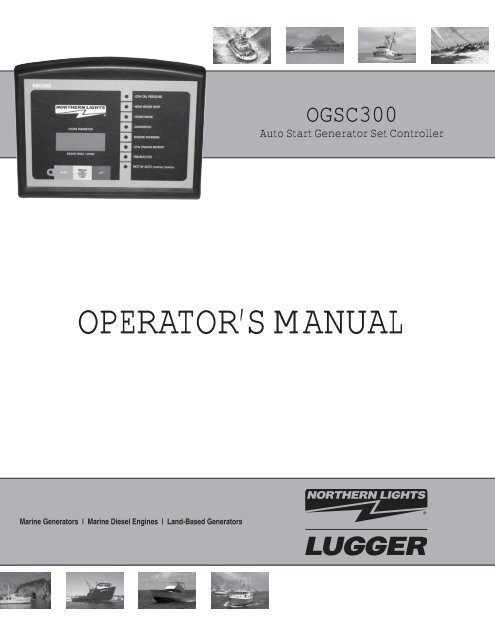
OGSC300<br />
<strong>Auto</strong> <strong>Start</strong> <strong>Generator</strong> <strong>Set</strong> <strong>Controller</strong><br />
OPERATOR’S MANUAL<br />
Marine <strong>Generator</strong>s | Marine Diesel Engines | Land-Based <strong>Generator</strong>s
<strong>Northern</strong> <strong>Lights</strong><br />
4420 14th Avenue N.W.<br />
Seattle, WA 98107<br />
Tel: (206) 789-3880<br />
Fax: (206) 782-5455<br />
Copyright ©2011 <strong>Northern</strong> <strong>Lights</strong>, Inc.<br />
All rights reserved. <strong>Northern</strong> <strong>Lights</strong>, and<br />
the <strong>Northern</strong> <strong>Lights</strong> logo are trademarks of<br />
<strong>Northern</strong> <strong>Lights</strong>, Inc.<br />
Printed in U.S.A.<br />
PART NO.: OGSC300 05/11
Please Read Manual Before Installing Unit<br />
Table of Contents.......................................................................................................................................... I<br />
Warranty Policy ........................................................................................................................................... II<br />
GSC400 Specifi cations..........................................................................................................................III- IV<br />
Table of Contents<br />
OPERATORS MANUAL<br />
for GSC400<br />
<strong>Auto</strong> <strong>Start</strong> <strong>Generator</strong> <strong>Set</strong> <strong>Controller</strong><br />
1 - GSC300 Product Number Itentifi cation ................................................... 1<br />
2 - Wiring Installation Guidelines ............................................................... 1-2<br />
2-1 Wiring Guidelines ................................................................................. 3<br />
3 - GSC400 System Operation ....................................................................... 4<br />
4 - Terminal Description ................................................................................. 5<br />
5 - Wiring Connection Diagram ......................................................................6<br />
5-1 Back Panel Layout ................................................................................ 6<br />
5-2 Wiring Connection Diagram Defi nitions ......................................................... 7<br />
6 - LED Layout ................................................................................................ 8<br />
6-1 LED Indicators ...................................................................................... 8<br />
7 - Programming The GSC300 <strong>Set</strong>tings........................................................ 9<br />
7-1 Numbering of LED’s and Location of .....................................................<br />
Mode Switch.............................................................................................. 10<br />
7-2 Sample Screen from PC Interface .......................................................11<br />
8 - Troubleshooting Guidelines ................................................................... 12<br />
9 - Technical Notes/Frequently Asked Questions ................................................ 13<br />
Proprietary Information<br />
This publication is the sole property of <strong>Northern</strong> <strong>Lights</strong>, Inc.<br />
It may not be reproduced in whole or part without the expressed written permission of <strong>Northern</strong> <strong>Lights</strong>, Inc.<br />
© <strong>Northern</strong> <strong>Lights</strong>, Inc. 2011. All rights reserved. Litho U.S.A. Publication number: OGSC300 5/11<br />
I
GSC300 Warranty Policy<br />
LIMITED WARRANTY POLICY: The <strong>Northern</strong> <strong>Lights</strong> GSC300 engine controller is warranted by the original<br />
manufacturer, DynaGen Technologies Inc. DynaGen Technologies Inc. hereafter known as the Seller warrants<br />
articles sold hereunder to be free from defects in material and workmanship. These express warranties are the<br />
sole warranties of the Seller and any other warranties, expressed, implied in law, or implied in fact, are<br />
hereby specifi cally excluded. The Seller’s sole obligation under its warranty shall be, at its option, to either<br />
issue a credit, or repair or replace any article or part thereof, which is proved to be defective. Any adjustment<br />
of credits will be based upon original billing prices. All warranties shall expire 5 years from date of shipment by<br />
the seller, unless otherwise specifi ed in other written communications from the Seller. Any replacement product<br />
provided to the Buyer shall be subject to the original warranty period, which will expire 5 years from the<br />
date of shipment of the original article. Notice of claimed breach of warranty must be given within the applicable<br />
period. No allowances shall be made to the Buyer for any transportation, duties, brokerage fees, labor<br />
costs, or parts adjustments or repairs, or any other work, unless said charges are authorized in writing, in<br />
advance, by the Seller. The Seller shall, in no event, be liable for special or consequential damages or for loss<br />
of profi t. The warranty shall not extend to any articles or parts thereof which have been installed, used, or serviced,<br />
other than in conformity with the Seller’s application specifi cations, manuals, bulletins, or instructions,<br />
or, if none, shall have been subjected to improper installation, misuse, or neglect. The warranties shall not<br />
apply to any materials or parts thereof, furnished by the Buyer, or acquired from others at the Buyer’s request<br />
and/or to the Buyer’s specifi cations or designs. The foregoing limitations on the Seller’s liability in the event of<br />
breach of warranty shall also be the absolute limit of the Seller’s liability in the event of the Seller’s negligence<br />
in manufacture, installation, service, or otherwise, with regard to the articles covered hereby, and upon the<br />
expiration of the stated warranty period, all such liabilities shall terminate.<br />
RETURNS: If any article is claimed to be defective in material or workmanship, the Seller, upon notice<br />
promptly given, will issue a written return material authorization (RMA) with shipping instructions for return to<br />
the Seller. All returns must be accompanied by an RMA number or shipments will not be accepted by the<br />
Seller. Articles which are returned as defective, but are found to meet the specifi cations agreed upon, will be<br />
subject to a re-testing charge. At the discretion of the Seller, unused and undamaged Standard Products may,<br />
under certain circumstances, be accepted back for credit or exchange. A restocking charge of 15% will apply.<br />
Unused custom designed products will not be accepted back for credit or exchange.<br />
For questions or comments regarding this product, contact:<br />
<strong>Northern</strong> <strong>Lights</strong><br />
Phone (206) 789-3880<br />
Fax (206) 782-5455<br />
Email: info@northern-lights.com<br />
Web: www.northern-lights.com<br />
OGSC300 05/11<br />
4II
Operating Voltage: 7 to 30 VDC continuous<br />
Zero volts operation for 100mS (assumes supply was 12 VDC before initiating<br />
starting)<br />
Operating Temperature:<br />
-400C to +850C (LCD Display operates from to -160C to 700C)<br />
Physical Dimensions:<br />
4.5” (H) x 5.5” (W) x 1.25” (D)<br />
Actual Unit Weight: 0.458 lbs<br />
Enclosure: High Impact Resistant, Injection Molded Plastic Enclosure<br />
Front Panel Indications<br />
-High intensity LED’s with regulated brightness<br />
LED Display<br />
Adjustments<br />
-Ultra-bright, Backlight LCD display with optimum viewing angle of 0 - 250 from perpendicular<br />
-Display Size (mm) 8 (W) x 32 (H) x 12.8 (D) x (2 line x 8 character display)<br />
Warm-up: 0-200 Seconds (After Oil Bypass Feature)<br />
Cool-Down: 0 - 812 Seconds<br />
Crank Disconnect: 12 to 140 Hz<br />
Overspeed: 40 - 200 Hz<br />
Crank Rest: 4 - 32 Seconds<br />
Delay on <strong>Start</strong>: 0 - 59 Seconds<br />
Crank Tries: 1 to 10<br />
Oil Bypass: 10 - 55 Seconds<br />
Low Battery Indication:<br />
Timer Adjustments<br />
7 - 35 VDC<br />
Glow Plug/Preheat: 0 - 255 Seconds<br />
Energize To Stop<br />
(ETS):<br />
GSC300 Specifi cations<br />
Energizes for 15 Seconds on failures, or energizes until 5 Seconds after engine speed<br />
goes to zero upon removing power from <strong>Start</strong>/Stop terminal or removing the unit from<br />
manual mode using the front panel buttons.<br />
OGSC300 05/11<br />
5III
GSC300 Specifi cations (Continued)<br />
Inputs<br />
Speed Sensing: -<strong>Generator</strong> Output Speed Sensing<br />
Maximum Input Voltage: 300VAC RMS<br />
Minimum Input Voltage: 0.7VAC RMS <strong>Generator</strong> Output Sensing<br />
-60Hz Rejection Filter Included<br />
-Loss of Speed Signal Included<br />
Sender/Failure Oil Pressure<br />
-Accepts standard industry low impedance (0-500<br />
Inputs:<br />
Coolant Temperature ohm) sender inputs (VDO, Stewart-Warner, Datcon,<br />
Fuel Level / Auxiliary Murphy, etc.)<br />
Input<br />
-Custom senders can be accommodated for in PC programming<br />
-Programmable for either switch or sender confi guration<br />
-Adjustable failure set-points<br />
Protection -Three on-board replaceable 40A fuses protect Fuel, Crank, and Timer Outputs<br />
-Reverse polarity protected<br />
-Short circuit & overload protection on annunciation outputs<br />
-Inputs are electrostatic discharge protected<br />
-Maximum power supply surge before damage: 1500V for 250us<br />
Outputs -All outputs switched to +battery (sourcing)<br />
-Fuel, Crank, and Timer 40A each, using standard 40A automotive relays<br />
Outputs:<br />
-Annunciation Outputs: 300mA individually, 350mA combined<br />
Connections -Removable terminal block for annunciation outputs and low power connections<br />
-0.25” spade terminals for high current and Main power inputs<br />
Programming -Windows based software interface utilizing the parallel port of your PC<br />
-Option of programming through 3-button interface (limited parameter adjustment) on<br />
the front panel or the PC Interface that has full parameter programming ability.<br />
-Needs no power to program using the PC Interface – uses power from parallel<br />
port of PC<br />
-Specifi cations May Change Without Notifi cation<br />
OGSC300 05/11<br />
IV<br />
6
1. GSC300 PRODUCT NUMBER IDENTIFICATION<br />
The GSC300 series catalog order number provides information pertaining to a specifi c model. The<br />
Product Number Identifi cation Table (see Table 1) provides details on the breakdown of the model<br />
number.<br />
Table 1 - IDENTIFICATION TABLE<br />
Position 1-6 Position 8 Position 10-11 Position 13-14<br />
Series Speed Range DC Voltage Labeling<br />
GSC300=GSC300 L=Low<br />
12=12 VDC<br />
LS=Standard<br />
H=High (Consult Factory) 24=24 VDC<br />
LX=Customized<br />
Example: The product number GSC300-L-12-LS would be described as follows:<br />
A GSC300 series automatic engine controller confi gured for a 12 VDC system.<br />
The controller is factory confi gured for low speed range (generator speed range) which includes standard<br />
labeling.<br />
A GSC300 serial number would be displayed as:<br />
GSC300-L-12-LS-00000<br />
2 WIRING INSTALLATION GUIDELINES<br />
Danger: Never work on the engine while its power is on. This controller does<br />
not generate a warning signal prior to automatic engine start. Warning signs should<br />
be placed on engine equipment indicating this important safety measure.<br />
INSTRUCTIONS<br />
Following these instructions will help avoid common installation problems during wiring and setup.<br />
• Battery must be disconnected before any wiring connections are made.<br />
• Wire length from the engine to the controller should not exceed 6 meters (20 feet).<br />
Wiring size and type should be as specifi ed below. Use stranded wire, since solid wire has a tendency to<br />
crack, break and loosen over time.<br />
OGSC300 05/11<br />
1
Types and Sizes:<br />
2 WIRING INSTALLATION GUIDELINES (CONTINUED)<br />
Terminal Wire Size (AWG) Current Max Function<br />
1 12 40A Fuel Output Terminal<br />
2 12 40A <strong>Auto</strong>(Battery +) Terminal Connection<br />
3 12 40A <strong>Auto</strong>(Battery +) Terminal Connection<br />
4 12 40A Crank Output Terminal<br />
5 12 40A Ground Terminal Connection<br />
6 12 40A Ground Terminal Connection<br />
7 12 40A Preheat/ETS Terminal<br />
8 12 40A Preheat/ETS Terminal<br />
9 18 100mA Speed Signal Connection<br />
10 18 100mA Speed Signal Connection<br />
11 18 300mA Overcrank (failure to start) Output<br />
12 18 300mA Overspeed Output<br />
13 18 300mA High Termp Output<br />
14 18 300mA Low Oil Output<br />
15 18 300mA Low Battery Output<br />
16 18 300mA Engine Run Output<br />
17 18 100mA Not In <strong>Auto</strong> Output<br />
18 18 300mA General Failure Output<br />
19 18 7ma <strong>Start</strong>/Stop Input<br />
20 18 7mA Oil Pressure Sender/Switch Input<br />
21 18 7mA Temperature Sender/Switch Input<br />
22 18 7mA Fuel Level/Auxiliary Sender/Switch Input<br />
OGSC300 05/11<br />
2
2.1 WIRING GUIDELINES<br />
1. DO NOT use wire smaller than 18 AWG as smaller wire has a tendency to crack and break over time.<br />
2. IMPORTANT: The connections supplying DC power to the GSC300 panel should preferably run<br />
directly from the battery posts with no splices or other connections. Avoid using chassis (aluminum or iron<br />
engine parts), as return conductor for battery negative voltage. Copper wiring is recommended. Failure<br />
to follow the above may result in erratic operation due to large voltage drops across wiring connections.<br />
A small fuse should be placed at the battery terminal to provide 12 volts to the Remote <strong>Start</strong> Contacts to<br />
ensure that a short along this line will not cause any damage.<br />
3. DO NOT exceed the maximum rated current and voltage on each of the controller outputs. DO NOT<br />
exceed 40A each for the Fuel Output, Crank Output or Preheat Output. DO NOT exceed 300mA individually,<br />
or 350mA combined, for the General Fault Output or Annunciation Outputs.<br />
4. 40Amp relays are rated for resistive ratings. When driving such loads as starter solenoids you must<br />
ensure proper de-rating of the relays. Consult factory for further details.<br />
5. Engine Sensor type MUST be selected and programmed properly to GSC300 (switch or sender type).<br />
Failure to do so may result in the controller not shutting down on true engine failure (Low oil pressure or<br />
high engine temperature).<br />
6. When installing engine sensors (oil pressure, engine temperature, fuel level) ensure the switches are<br />
connected to ground circuit through the engine sensor. Damage will occur to controller unit if the<br />
sensor<br />
input terminals (Terminal #’s 20, 21 and 22) are connected to +Battery.<br />
7. When using engine sensors that are the resistive type the proper manufacturer of the sender<br />
MUST<br />
be selected during programming. Failure to select the correct manufacturer type will cause inaccurate<br />
readings as well as failure to protect the engine during a fault condition.<br />
8. To verify the operation of engine controller outputs, measure voltage (i.e. meter in volts) when outputs<br />
should be ON.<br />
9. To verify the operation of the Preheat Output, measure the resistance between the Preheat terminals<br />
when the Preheat Output is ON, it should read a closed circuit (i.e. zero ohms). When the output is OFF<br />
there should be an open circuit between the terminals (very high resistance).<br />
10. Speed sensing input terminals (Terminal #’s 9 and 10) do not have polarity sensitivity therefore the<br />
AC generator output leads can be connected in any polarity confi guration to the controller speed sensing<br />
terminals. Do not exceed 300VAC on speed sensing input terminals.<br />
OGSC300 05/11<br />
3
12VDC RELAYS MUST<br />
BE INSTALLED FOR 12VDC<br />
SYSTEM OPERATION<br />
3 GSC300 12/24VDC SYSTEM OPERATION<br />
The GSC300 controller is designed to operate in either 12 or 24VDC system voltages. When operating in<br />
12VDC systems the Fuel and Preheat/ETS relays need to be the 12VDC relay type. When operating in<br />
24VDC systems these relays need to be the 24VDC relay type. Contact the factory if relays are required. 24<br />
VDC will require reprogramming.<br />
Approved relays for 12 or 24VDC system operation are as follows:<br />
• <strong>Northern</strong> <strong>Lights</strong> P/N 22-42047 for 12VDC operation<br />
• <strong>Northern</strong> <strong>Lights</strong> P/N 22-40085 for 24VDC operation<br />
OGSC300 05/11<br />
4<br />
24VDC RELAYS MUST<br />
BE INSTALLED FOR 24VDC<br />
SYSTEM OPERATION
Term # Description<br />
4 TERMINAL DESCRIPTION<br />
Table 2 Terminal Description<br />
1 Fuel Output provides 40A maximum. Fuel Output closes to +12/24VDC when start signal is received,<br />
and opens when either an engine failure occurs or when Cool Down period has ended.<br />
2, 3 <strong>Auto</strong> Terminals. Main +Battery power connection to controller. These terminals are internally connected<br />
together on GSC300 controller.<br />
4 Crank Output provides 40A maximum. Crank Output closes to +12/24VDC during cranking, and opens<br />
when the engine has started, or during Crank Rest.<br />
5, 6 Main Battery Ground connection for the controller module. A good ground connection, directly from<br />
the battery, is required for proper operation. These terminals are internally connected together on<br />
GSC300 controller.<br />
7, 8 Preheat/ETS Output provides a set of dry contacts between terminals #7 and #8. When this output is<br />
energized terminals #7 and #8 are connected together. When output is OFF terminals #7 and #8 have<br />
no connection.<br />
9, 10 Speed 1. Speed Signal Input for Crank Disconnect, Engine Run, and Overspeed sensing. 300VAC<br />
max input voltage. Speed sensing input terminals (T#9, 10) do not have polarity sensitivity therefore<br />
the AC generator output leads can be connected in any polarity confi guration. Do not exceed 300VAC<br />
on speed sensing input terminals.<br />
11 Overcrank Annunciation Output closes to +12/24VDC on Overcrank Failure. 300mA max.<br />
12 Overspeed Annunciation Output closes to +12/24VDC on Overspeed Failure. 300mA max.<br />
13 High Temp Output closes to +12/24VDC upon High Temp Failure. 300mA max.<br />
14 Low Oil Output closes to +12/24VDC upon Low Oil Failure. 300mA max.<br />
15 Low Battery Output closes to +12/24VDC on Low Battery Condition. 300mA max.<br />
16 Engine Run Output closes to +12/24VDC on Engine Run Condition. 300mA max.<br />
17 Not In <strong>Auto</strong> Output closes to +12/24VDC when unit is not in auto. 300mA max.<br />
18 General Failure Output closes to +12/24VDC on a General Failure. 300mA max.<br />
19 <strong>Start</strong> Stop Input. Apply +12/24VDC to this terminal while unit is in <strong>Auto</strong> Mode to start engine. Remove<br />
+12/24VDC to stop engine or enter Cool-Down mode.<br />
20 Low Oil Pressure sensor input. This sensor can be the resistive type (Sender) or can be the switch<br />
type. The proper type of sensor must be selected during GSC300 controller programming. The sender<br />
or switch must be connected to ground for proper operation. If +Battery is connected to input terminal<br />
this can result in damaged to GSC300 controller. When using a sender, the proper sender manufacturer<br />
must be selected as each sender manufacturer’s characteristics are different; the sender failure<br />
set-point must also be selected. When using a switch NO or NC much be selected from the programming<br />
menu. NO refers to the state of the contacts during normal engine operation, therefore NO refers<br />
to normally open at normal engine run and close to ground on low oil pressure failure.<br />
21 High Engine Temperature sensor input. This sensor can be the resistive type (Sender) or can be the<br />
switch type. The proper type of sensor must be selected during GSC300 controller programming. The<br />
sender or switch must be connected to ground for proper operation. If +Battery is connected to input<br />
terminal this can result in damaged to GSC300 controller. When using a sender, the proper sender<br />
manufacturer must be selected as each sender manufacturer’s characteristics are different; the sender<br />
failure set-point must also be selected. When using a switch the switch must be the NO type on normal<br />
engine run and close to ground on failure.<br />
22 Fuel Level sensor or Auxiliary failure input. This sensor can be the resistive type (Sender) or can be<br />
the switch type. The proper type of sensor must be selected during GSC300 controller programming.<br />
The sender or switch must be connected to ground for proper operation. If +Battery is connected to input<br />
terminal this can result in damaged to GSC300 controller. When using a sender, the proper sender<br />
manufacturer must be selected as each sender manufacturer’s characteristics are different. When using<br />
a switch the switch must be the NO type on normal engine run and close to ground on failure.<br />
OGSC300 05/11<br />
5
5 WIRING CONNECTION DIAGRAM<br />
Figure 1 - Wiring Connections for the GSC300<br />
(Refer to schematics No. B-9696 and B-9691 on pages 24 and 25.)<br />
5.1 BACK PANEL LAYOUT<br />
OGSC300 05/11<br />
6
1. General Failure Conditions<br />
2. Not In <strong>Auto</strong><br />
3. Low Battery Voltage Alarm<br />
4. Oil Pressure Input<br />
5.2 WIRING CONNECTION DIAGRAM DEFINITIONS<br />
OGSC300 05/11<br />
7<br />
5. Coolant Temperature Input<br />
6. Fuel Level/Auxiliary Input<br />
7. Speed Signal Sensing<br />
8. Adjustable Input Programming<br />
1: GENERAL FAILURE CONDITIONS: The following conditions can cause the GSC300 controller to shutdown the engine-generator<br />
system unexpectedly:<br />
Auxiliary Failure (“XTR_FAIL”) Extra failure is indicated by a fl ashing RED Low oil pressure LED<br />
Low Oil Pressure Low Oil pressure is indicated by a steady on RED Low oil pressure LED<br />
High Coolant Temperature High coolant temperature is indicated by a steady on RED High water temp LED<br />
Overcrank Overcrank failure is indicated by a steady on RED Overcrank LED<br />
Overspeed Overspeed failure is indicated by a steady on RED Overspeed LED<br />
Loss of Speed (“SPDLOSS”) Loss of speed signal is indicated by a fl ashing RED Overspeed LED<br />
2: NOT IN AUTO: When the controller is in the OFF Mode, the NOT IN AUTO LED will illuminate and the NOT IN AUTO Output will<br />
be triggered. During this OFF mode <strong>Auto</strong>matic engine starting is disabled. The LCD display will read “OFF”, and the backlight on the<br />
LCD display will be off.<br />
NOTE: + Battery must be permanently connected to the main power terminal for the NOT IN AUTO feature.<br />
3: LOW BATTERY VOLTAGE ALARM: When the battery voltage drops below the user defi ned set point which can be programmed<br />
between 7 and 35VDC, the engine controller displays a Low Battery Condition. The Low battery warning Led will be illuminated at<br />
any time during OFF, AUTO and Manual run modes. The LCD display will indicate the message: “LOW_BATT”. The LOW battery<br />
warning will be disabled during failure conditions.<br />
4: LOW OIL INPUT: The Low Oil Input can be wired to a resistive sender or from a NO or NC type switch. NO / NC refers to the<br />
state of the contacts during normal engine operation (engine oil pressure ok). When utilizing a resistive sender the display units are<br />
fi xed in PSI by the PC programming interface, and a failure set-point must be selected from the programming menu.<br />
Note: The oil input failure is disabled during the Oil Bypass time.<br />
5: HIGH TEMPERATURE INPUT: The high temperature input can be wired to a resistive sender or from a NO type switch.<br />
For proper operation while using a switch, the switch must be the NO type which closes to ground upon failure. When utilizing<br />
a resistive sender the display units are fi xed in Fahrenheit by the PC programming interface, and a failure set-point<br />
must be selected from the programming menu.<br />
Note: The engine temperature failure is disabled during the Oil Bypass time.<br />
6: FUEL LEVEL/AUXILIARY INPUT: The Fuel level/Aux input can be wired to a resistive sender or from a NO type switch.<br />
For proper operation while using a switch, the switch must be the NO type which closes to ground upon failure. If this input is<br />
used as a sender, no failure will be indicated. The sender option is solely for Fuel Level/Auxiliary Level Display on the LCD.<br />
<strong>Northern</strong> <strong>Lights</strong>, Inc. uses this input to connect the engine shutdown switches as a backup to the primary shutdown inputs.<br />
7: SPEED SIGNAL SENSITIVITY: The controller will accept to a maximum of 300VAC, 60Hz from direct generator output<br />
for speed sensing. The following values are minimal recommended voltages for speed signal sensing:<br />
20Hz - .075V (75mV)<br />
60HZ - .6V (600mV)<br />
8: HOUR METER: The controller displays a log of total accumulated generator running hours. <strong>Generator</strong> Run times will be<br />
displayed on the controllers display screen. The display represents both hours and minutes in the form 123456:7. The last digit<br />
on the hour meter will represent the time in 1/10 of an hour. Please note that although the hour meter displays time in hours and<br />
minutes, it will record up to the nearest second. If the generator was operated for a 3 minute period and then stopped the running<br />
time is stored in permanent memory and then adding to the next running period. The same would be true if the controller were to<br />
enter a failure mode as the controller would permanently store the remaining time for the next running cycle.
LED Appearance Condition/Failure<br />
6 LED LAYOUT<br />
Figure 3 - Front View of GSC300<br />
6.1 LED INDICATIONS<br />
Table 3: FRONT PANEL LED INDICATORS<br />
Not in <strong>Auto</strong> LED is ON. Unit is in OFF state, and automatic starting is disabled<br />
No LED’s ON “OFF”, no +12/24VDC to main power terminal.<br />
Steady Low Oil LED Low Oil Pressure Failure<br />
Flashing Low Oil LED Auxiliary Input Failure<br />
Steady High Temperature LED Over Temperature Failure<br />
Steady Overcrank LED Engine-generator failed to start after the specifi ed number of cranking<br />
attempts.<br />
Steady Overspeed LED Speed Signal present above Overspeed setting<br />
Flashing Overspeed LED The speed signal was Zero while running. The engine has stalled (overload<br />
or lack of fuel), or the speed signal has been lost.<br />
Steady Engine Running LED Engine <strong>Controller</strong> is in running mode of operation.<br />
Flashing Engine Running LED Crank Rest period. Cranking will resume soon.<br />
OGSC300 05/11<br />
8
Using the Front Panel Interface:<br />
7 PROGRAMMING THE GSC300 SETTINGS<br />
The following table shows the LED’s that correspond to the various settings of the various parameters.<br />
To enter the controller into Program Mode, you need to turn the small switch at the bottom<br />
edge of the controller to the program position (See Diagram on Pg 5). This Mode Switch can be<br />
set using a ballpoint pen or small tool to allow the controller to be put into Program Mode. The fi rst<br />
three LED’s (3, 2 & 1) correspond to which Parameter is being adjusted, and the next three (6, 5<br />
& 4) LED’s show the Value for that particular Parameter.<br />
LED 1 = Low oil pressure<br />
LED 2 = High water temp<br />
LED 3 = Overcrank<br />
LED 4 = Overspeed<br />
LED 5 = Engine Running<br />
LED 6 = Low engine battery<br />
LED7 = Preheat/ETS<br />
LED8 = NOT IN AUTO (starting disabled)<br />
The picture on the next page shows the LED numbering and the location of the Mode Switch.<br />
The highlighted circle in the table refers to the LED being illuminated.<br />
Parameter LED’s 3,2 &1 LED’s 6,5 &4<br />
Crank Tries 1 2 3 4 5 6 7 8<br />
Crank Time 5 10 15 20 25 30 35 40<br />
Rest Time 0 5 10 15 20 25 30 35<br />
Preheat Time 0 5 10 15 20 35 30 35<br />
Cool-Down 0 32 64 96 128 160 192 224<br />
Preheat/ETS/<br />
Pre- ETS Warm- N/A N/A N/A N/A N/A<br />
Warm-up<br />
heat<br />
Up<br />
Warm-Up 0 28 56 84 112 140 168 196<br />
To scroll through the parameters simply press the <strong>Auto</strong> button on the front panel of the<br />
GSC300. To scroll through the range of values for that parameter simply press the Manual<br />
<strong>Start</strong> button. To program the value into the controller’s memory, press the OFF button. In<br />
this manner the settings of the controller can be adjusted by simply using the three buttons on<br />
the front panel of the controller. Be sure to press the OFF button when you have selected the<br />
parameter value wanted.<br />
OGSC300 05/11<br />
9
7.1 NUMBERING OF LED’S AND LOCATION OF MODE SWITCH<br />
Programming Using the PC Interface<br />
The GSC300 can also be programmed using the PC interface. Detailed instructions on the<br />
PC interface are included with the GSC300 Confi gurator software. A sample interface screen is<br />
illustrated on the following page.<br />
OGSC300 05/11<br />
10
7.2 SAMPLE SCREEN FROM PC INTERFACE<br />
NOTE: Factory default settings are outlined in the photo below.<br />
Figure 5:<br />
OGSC300 05/11<br />
11
8 TROUBLESHOOTING GUIDELINES<br />
TROUBLE POSSIBLE CAUSE SUGGESTED ACTION<br />
Unit does not operate when<br />
powered to test mode<br />
Engine starts and immediately<br />
goes into Overspeed shutdown<br />
Power leads to unit are reversed Confi rm correct wiring for ground and +bat,<br />
and re-attempt testing.<br />
Bad ground connection from engine to<br />
controller unit.<br />
OGSC300 05/11<br />
12<br />
Run wire directly from battery - to the ground<br />
terminal #11on controller unit.<br />
Improper Overspeed setting Verify the Overspeed setting with PC confi guration<br />
software. Confi rm that engine’s governor<br />
is properly calibrated for its intended use.<br />
Engine does not crank Battery is low or terminals are dirty Clean terminals and re-charge battery<br />
Engine cranks but does not<br />
start<br />
Engine starts but shuts down<br />
after “Oil Bypass TM period”<br />
due to low oil/high temp/Aux<br />
input<br />
Crank circuitry wiring improperly<br />
connected<br />
Bad ground connection from engine to<br />
controller<br />
Crank relay damaged. Or on board fuse<br />
is blown<br />
Refer to engine control wiring section and<br />
check crank connections<br />
Run wire directly from battery - to the ground<br />
terminal #5 & 6, on controller unit.<br />
Check wiring, in line fuse and slave relay.<br />
Replace fuse, relay and re-test controller<br />
Out of fuel Check fuel level, add fuel if necessary<br />
Ignition control wiring not installed<br />
properly<br />
Refer to engine control wiring section and<br />
check ignition connections<br />
Fuel relay and or fuse damaged Check fuel relay and fuse, replace if damaged<br />
or blown.<br />
Oil/Temp/Auxiliary input wiring improp- Check wiring for proper connections.<br />
erly connected.<br />
Incorrect programming of sensor inputs. Check programming of oil pressure, engine<br />
temperature and aux input. Ensure that the<br />
sensor type is properly programmed to controller<br />
unit (Sender / Switch type)<br />
Flashing Overspeed LED Speed signal improperly connected,<br />
missing, or damaged.<br />
Crank output damaged, not working, or<br />
fuse blown on starter output<br />
Steady Oil LED immediately<br />
on start-up, without engine<br />
actually cranking or starting.<br />
Display Parameter for Temperature,<br />
Oil or Fuel displayed<br />
as >>> or > ABOVE or
9 TECHNICAL NOTES ON FREQUENTLY ASKED QUESTIONS<br />
1. <strong>Controller</strong> Memory Clear Time<br />
The GSC300 needs 10 seconds for its memory to clear. When the power to the controller is turned<br />
off and then back on again without waiting 10 seconds to clear the memory, a loss of speed will may<br />
be indicated by the GSC300 (if controller is in AUTO mode and start signal is activated) because the<br />
controller remains in run mode and senses that the generator has stopped. This would be indicated by a<br />
Flashing Overspeed LED. By leaving the GSC300 main power OFF for 10 seconds before main power<br />
is re-applied this allows the clearing the memory and it will function as intended.<br />
2. Step Down Transformer Use On Speed Sensing Cable With Inverter Systems<br />
In some applications engine controllers are used on generators where there is no utility connection and<br />
inverters are used to provide AC power instead of a utility. Inverters can produce harmonics that can<br />
cause small AC signals to appear on wires that are near any power lines being fed by the inverter. If the<br />
generator output wires are located close to a line being powered by an inverter, a small AC signal can<br />
appear on the generator output lines when the inverter is on. This signal can cause the engine controller<br />
to react as if the generator is running if the speed sensing wires are connected to the generator output<br />
lines. This small AC signal can cause the controller to appear to have a Low Oil Failure when the remote<br />
start contacts are closed or the controller is put in the manual/test mode. The controller may think the<br />
generator is already running and immediately check to make sure there is oil pressure. Since the engine<br />
really hasn’t started yet, there is no oil pressure and the controller sees a low oil fault. This is seen as<br />
the Oil LED turning on steady even before the engine starts to engage the starter.<br />
Without this false speed signal the controller will not look for oil pressure until the engine has started to<br />
run and the crank disengages if oil verifi cation is disabled. Simply installing a small transformer between<br />
the generator output and the speed sensing terminals on the controller can eliminate this false speed<br />
signal. This transformer should be rated for 120 or 240 volts on the input or primary coil (depending on<br />
the generator output voltage you are using for speed sensing), and have an output voltage of around<br />
12VAC on the secondary of the transformer. The two wires from the secondary of the transformer are<br />
connected to the two wires of the speed sensing terminals on the GSC300 controller. The step-down<br />
transformer acts to reduce the false speed signal on the line to a level that the engine controller will not<br />
recognize as the engine running. A common size transformer that would serve this purpose would be<br />
24VA.<br />
Figure 6: Step Down Transformer Connections on Speed Sensing Cable<br />
OGSC300 05/11<br />
13
OGSC300 05/11<br />
14
OGSC300 05/11<br />
15
OGSC300 05/11<br />
16
OGSC300 05/11<br />
17
www.northern-lights.com<br />
4420 14th Ave. NW., Seattle WA 98107<br />
Tel: (206) 789-3880 • 1-800-762-0165 • Fax: (206) 782-5455<br />
<strong>Northern</strong> <strong>Lights</strong> and Lugger are registered trademarks of <strong>Northern</strong> <strong>Lights</strong>, Inc.<br />
© 2011 All rights reserved. Litho USA.


