
You also want an ePaper? Increase the reach of your titles
YUMPU automatically turns print PDFs into web optimized ePapers that Google loves.
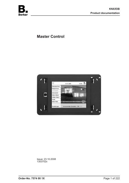
<strong>Master</strong> <strong>Control</strong><br />
Issue: 23.10.2008<br />
1353702x<br />
KNX/EIB<br />
Product documentation<br />
Order-No. 7574 00 1X Page 1 of 222
Content<br />
1 Product definition ................................................................................................................ 4<br />
1.1 Product catalogue ........................................................................................................... 4<br />
1.2 Function .......................................................................................................................... 4<br />
1.3 Accessories .................................................................................................................... 5<br />
2 Fitting, electrical connection and operation ..................................................................... 6<br />
2.1 Safety instructions .......................................................................................................... 6<br />
2.2 Device components ........................................................................................................ 7<br />
2.3 Fitting and electrical connection ..................................................................................... 8<br />
2.4 Commissioning ............................................................................................................. 10<br />
2.5 Operation ...................................................................................................................... 12<br />
3 Technical data .................................................................................................................... 14<br />
4 Software description ......................................................................................................... 15<br />
4.1 Software specification ................................................................................................... 15<br />
4.2 Software "...590101" ..................................................................................................... 16<br />
4.2.1 Scope of functions ................................................................................................. 16<br />
4.2.2 Software information ............................................................................................. 18<br />
4.2.3 Object table ........................................................................................................... 19<br />
4.2.4 Functional description ........................................................................................... 37<br />
4.2.4.1 Basic settings during project planning ........................................................... 37<br />
4.2.4.1.1 General parameters ............................................................................... 37<br />
4.2.4.1.2 LCD lighting ............................................................................................ 42<br />
4.2.4.1.3 Date and time ......................................................................................... 43<br />
4.2.4.1.4 Download behaviour .............................................................................. 45<br />
4.2.4.1.5 Colour schemes ..................................................................................... 46<br />
4.2.4.1.6 Image list ................................................................................................ 47<br />
4.2.4.1.7 Preview and resource monitor ................................................................ 49<br />
4.2.4.2 Screen pages ................................................................................................. 50<br />
4.2.4.2.1 General page structure .......................................................................... 50<br />
4.2.4.2.2 Display elements .................................................................................... 54<br />
4.2.4.2.3 Status line .............................................................................................. 64<br />
4.2.4.2.4 Copying display elements and pages .................................................... 65<br />
4.2.4.2.5 Connecting pages .................................................................................. 66<br />
4.2.4.3 Service page .................................................................................................. 67<br />
4.2.4.3.1 Structure ................................................................................................. 67<br />
4.2.4.3.2 Display and system settings ................................................................... 68<br />
4.2.4.3.3 Administrator settings ............................................................................. 70<br />
4.2.4.3.4 Passwords .............................................................................................. 75<br />
4.2.4.3.5 IP settings .............................................................................................. 76<br />
4.2.4.4 Fault messages ............................................................................................. 79<br />
4.2.4.4.1 Creating fault messages and the message window ............................... 79<br />
4.2.4.4.2 Acknowledgement and message list ...................................................... 81<br />
4.2.4.5 Light scene function ....................................................................................... 83<br />
4.2.4.5.1 Adding light scenes and light scene groups ........................................... 83<br />
4.2.4.5.2 Specifying light scene values ................................................................. 85<br />
4.2.4.6 Timer switch function ..................................................................................... 87<br />
4.2.4.6.1 Creating timer switch channels .............................................................. 87<br />
4.2.4.6.2 Setting switching times ........................................................................... 89<br />
4.2.4.6.3 Astro and random function ..................................................................... 92<br />
4.2.4.7 Timers ............................................................................................................ 94<br />
4.2.4.8 Logical links ................................................................................................... 95<br />
4.2.4.9 Multiplexer ..................................................................................................... 97<br />
4.2.4.10 Datalogger ..................................................................................................... 99<br />
4.2.4.10.1 Datalogger recording .............................................................................. 99<br />
Order-No. 7574 00 1X<br />
KNX/EIB<br />
Product documentation<br />
Page 2 of 222
4.2.4.10.2 Datalogger display ............................................................................... 103<br />
4.2.4.11 Presence simulation .................................................................................... 105<br />
4.2.4.11.1 Recording a telegram sequence .......................................................... 105<br />
4.2.4.11.2 Playing a telegram sequence back ...................................................... 108<br />
4.2.4.12 Signalling system ......................................................................................... 110<br />
4.2.4.12.1 Introduction and basic principles .......................................................... 110<br />
4.2.4.12.2 Detector ................................................................................................ 115<br />
4.2.4.12.3 Arming .................................................................................................. 119<br />
4.2.4.12.4 Alarms .................................................................................................. 122<br />
4.2.4.12.5 Fault ..................................................................................................... 124<br />
4.2.4.12.6 Event memory ...................................................................................... 125<br />
4.2.4.12.7 Behaviour after a device reset ............................................................. 126<br />
4.2.4.13 e-mail messages .......................................................................................... 127<br />
4.2.4.13.1 Introduction .......................................................................................... 127<br />
4.2.4.13.2 Displaying e-mail messages ................................................................. 128<br />
4.2.4.13.3 Sending e-mail messages .................................................................... 132<br />
4.2.4.14 RSS newsfeeds ........................................................................................... 134<br />
4.2.4.14.1 Introduction .......................................................................................... 134<br />
4.2.4.14.2 Displaying RSS newsfeeds .................................................................. 135<br />
4.2.4.15 Group addresses ......................................................................................... 139<br />
4.2.4.16 Options of the ETS plug-in ........................................................................... 140<br />
4.2.5 Parameters .......................................................................................................... 141<br />
4.3 PC Client software ...................................................................................................... 204<br />
4.3.1 Introduction, installation and program start ......................................................... 204<br />
4.3.2 Connection settings, data exchange and device update ..................................... 206<br />
4.3.3 Configuration data (IP, e-mail, RSS) ................................................................... 210<br />
4.3.4 Remote operation ................................................................................................ 218<br />
5 Appendix ........................................................................................................................... 220<br />
5.1 Index ........................................................................................................................... 220<br />
Order-No. 7574 00 1X<br />
KNX/EIB<br />
Product documentation<br />
Page 3 of 222
1 Product definition<br />
1.1 Product catalogue<br />
Product name: <strong>Master</strong> <strong>Control</strong><br />
Use: <strong>Control</strong>ler<br />
Design: uP (flush-mounting type)<br />
Order-No. 7574 00 1X<br />
1.2 Function<br />
The panel is used to display statuses with an KNX/EIB installation and to control system functions.<br />
The display elements are shown on a colour TFT monitor at a resolution of 320 x 240<br />
pixels (5.7" / 4,096 colours). The operating elements are controlled by touching the TFT monitor<br />
(touch screen).<br />
Up to 50 freely-programmable screen pages, each with up to 16 display elements, can be used<br />
for operation and displaying. The maximum total amount of display elements in the panel is 400.<br />
Up to four programmable function keys can be allocated to each display element. Both basic<br />
functions, such as switching, dimming and blinds, and also complex functions such as value encoders,<br />
date, limit values, etc., can also be configured.<br />
Coloured images, in BMP and JPG format, can be included as wallpapers to aid desktop<br />
design, and can also be used as icons.<br />
The panel also possesses an Ethernet interface. Various embedded IP protocols allow up to<br />
five synchronised and password-protected mailboxes and the text contents of e-mails to be<br />
opened. It is also possible to send predefined e-mails. In addition, RSS news feeds can be displayed<br />
on the panel's colour display.<br />
The display and operating functions of the panel can be visualised 'from a distance' using easyto-install<br />
PC Client software and can be operated simultaneously (remote communication). The<br />
Ethernet interface also permits user-orientated configuration and commissioning of the panel.<br />
A synchronisable real-time clock is available for setting up time switch functions and for logging<br />
events. Events or any other actions can be forwarded by a switching command using predefined<br />
e-mails. In addition, the panel can be programmed with up 24 light scenes with 32 actuator<br />
groups.<br />
In addition, the panel can be used to implement a presence simulation and a datalogger functionality.<br />
The presence simulation can, for example give those outside the impression that a<br />
house is lived in, even though the owners are away. The owners can record any simulations<br />
over periods of time and play them back at any time.<br />
The datalogger provides the option of recording data, received from the KNX/EIB, in various<br />
formats, and displaying them on the unit. The data recorded by the datalogger can also be forwarded<br />
by e-mail.<br />
If necessary, a signalling system can provide a security-orientated system to monitor doors and<br />
windows. Up to two different signalling areas (internal / external) can be armed and monitored<br />
for break-ins and sabotage. Thus visual and acoustic alarming is possible using additional KNX/<br />
EIB components (e.g. switching actuators) in conjunction with alarm encoders (flash light, internal<br />
siren).<br />
There are appropriate special pages set up for timer switch functions, e-mail boxes, light<br />
scenes, fault messages, message list, signalling system and the setup of system functions.<br />
Four password levels allow controlled access to different functions. For this one of four password<br />
levels can be allocated to each screen.<br />
Commissioning can take place both via the bus and via an integrated USB port and also, to a<br />
certain extent, via the Ethernet port. The panel can be installed horizontally (preferred) or vertically.<br />
Order-No. 7574 00 1X<br />
Product definition<br />
Page 4 of 222
1.3 Accessories<br />
Flush-mounting box for mini touch pad Order-No.7590 00 21<br />
Masking frame for <strong>Master</strong> <strong>Control</strong> Order-No.7574 01 ..<br />
Order-No. 7574 00 1X<br />
Product definition<br />
Page 5 of 222
2 Fitting, electrical connection and operation<br />
2.1 Safety instructions<br />
Electrical equipment must be installed and fitted by qualified electricians. The applicable<br />
accident prevention regulations must be observed.<br />
Disconnect (switch off miniature circuit-breaker) before working on the device or exchanging<br />
the connected loads, otherwise there is a danger of electric shocks.<br />
Do not operate the screen with sharp or pointed objects. The touch-sensitive surface<br />
may be damaged.<br />
Do not use sharp objects for cleaning. Do not use sharp cleaning agents, acids or organic<br />
solvents.<br />
Failure to observe the instructions may cause damage to the device and result in fire and<br />
other hazards.<br />
Order-No. 7574 00 1X<br />
Fitting, electrical connection and operation<br />
Page 6 of 222
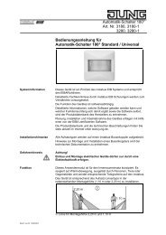
2.2 Device components<br />
Order-No. 7574 00 1X<br />
picture 1: Device components, front side<br />
picture 2: Device components, rear side<br />
(1) Colour TFT monitor (touch screen)<br />
(2) USB connection on the front side of the device (USB type B connector / located behind the<br />
design cover)<br />
(3) USB connection on the rear side of the device (flat connector / run to the front of the device<br />
using a flat cable)<br />
(4) KNX/EIB bus connection<br />
(5) Mains voltage connection<br />
(6) Programming LED (red)<br />
(7) Programming key<br />
(8) Ext. connection for future extensions, e.g. membrane keyboard<br />
(9) Reset button<br />
(10) Reset LED (red)<br />
(11) 8-pin Ethernet connection sockets<br />
i The programming button and LED are only accessible from the rear side of the device. If<br />
possible load the physical address into the device before final mounting(see chapter 2.4.<br />
Commissioning).<br />
Dimensions:<br />
approx. width (B): 220 mm / height (H): 140 mm / depth (D): 48 mm<br />
Without decorative cover frame and concealed installation housing.<br />
Fitting, electrical connection and operation<br />
Page 7 of 222
2.3 Fitting and electrical connection<br />
DANGER!<br />
Electrical shock when live parts are touched.<br />
Electrical shocks can be fatal.<br />
Before working on the device, enable all the corresponding miniature circuit<br />
breakers. Cover up live parts in the working environment.<br />
Connecting and mounting the device<br />
o Mount the installation housing (12) in the right position - aligned horizontally or vertically - in<br />
the wall (masonry or cavity wall).<br />
Horizontal mounting: arrow TOP points upwards. Vertical mounting: arrow TOP points left.<br />
Insert bus and 230 V cables, and, as necessary, Ethernet connection cable through the appropriate<br />
openings in the housing.<br />
i Recommendation: mount at eye level for optimum reading.<br />
i During installation, use the original up housing (<strong>Berker</strong> order no. 7590 00 211), in order to<br />
maintain the protection class II.<br />
o Pull the included hose over the unjacketed mains voltage wires. Mount the KNW/EIB connection<br />
terminal to the bus cable.<br />
o Connect mains voltage AC 230 V ~ to the terminals L N (5).<br />
o Connect bus cable to the BUS terminal (4).<br />
o If the device is to be connected to a local network, the Ethernet connection should also be<br />
setup.<br />
- For Ethernet connections with a standard installation cable:<br />
Connect the Ethernet cable provided in the packaging to the Ethernet adapter connector<br />
('Keystone'). Remove the jacketing of the Ethernet cables, do not remove the insulation<br />
and insert it in the lid of the adapter connector. In so doing, ensure correct polarity (colour<br />
allocation of the wire pairs in the installation and on the connection adapter EIA/TIA-568-A<br />
or -B). Cut off any excess wire and push the lid onto the adapter connector correctly.<br />
Then, insert one end of the enclosed mini patch cable into the Ethernet socket of the panel<br />
and the other into the mounted Ethernet adapter connector.<br />
- For Ethernet connection with a standard patch cable:<br />
Insert the patch cable directly into the Ethernet connection socket of the panel.<br />
i The pins of the Ethernet connection integrated in the table are assigned according to<br />
EIA/TIA-568-B.<br />
Order-No. 7574 00 1X<br />
Fitting, electrical connection and operation<br />
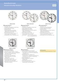
picture 3: Mounting with installation housing and decorative cover<br />
Page 8 of 222
o Insert the device in the installation housing (12) and fix it. Use the screws (14) provided.<br />
i Before inserting the device in the installation housing, load the physical address to the<br />
device using the ETS (see chapter 2.4. Commissioning).<br />
i Before inserting the device in the installation housing, ensure that no cables are crushed or<br />
bent.<br />
o Attach the decorative frame (15) and push it on.<br />
i Do not attach the decorative frame if the device is still to be programmed with the project<br />
planning data after mounting. The USB connection socket of the panel must be accessible<br />
on the front of the device.<br />
Order-No. 7574 00 1X<br />
Fitting, electrical connection and operation<br />
Page 9 of 222
2.4 Commissioning<br />
Commissioning<br />
After installation of the device and connection of the bus line, the mains supply and, if necessary,<br />
of the Ethernet cable, the device can be put into operation. Commissioning coil actuator is<br />
essentially confined to the installation of the USB driver and device programming via the ETS.<br />
The following procedure is generally recommended...<br />
Install the USB drivers<br />
Commissioning the panel may take some time, depending on the scope of project planning. To<br />
shorten the loading time of the application and all the project planning data, we recommend programming<br />
the device directly via USB. To allow USB device programming, a USB driver must<br />
be installed on the commissioning PC.<br />
To ensure correct installation of the USB driver, the panel must not be connected to the PC before<br />
installing the driver. The driver required for USB programming is supplied together with the<br />
project planning software (plug-in) of the panel. When the project planning software has been<br />
completed, there is the option of installing the USB driver automatically.<br />
o Install the project planning software of the panel. At the end of the installation process, start<br />
the automatic USB driver installation application.<br />
i Two drivers are installed during automatic installation. Firstly, the actual USB driver is installed,<br />
and immediately after that a virtual COM port is installed, which is important for the<br />
USB connection of the panel to function correctly. For this reason, do not cancel the installation<br />
after the first step!<br />
i The appropriate access rights in the operating system are required for driver installation.<br />
i Some PC operating systems test during installation whether the USB drivers have certificates.<br />
The appropriate messages can be ignored and installation continued.<br />
Programming the physical address<br />
The physical address is programmed using a KNX/EIB data interface in the ETS programming.<br />
The programming button (7) and LED (6) must be accessible on the rear side of the device.<br />
In addition, the project planning software must be installed and an appropriate device inserted in<br />
the project in the ETS and a physical address assigned.<br />
o Switch on the mains supply to the device.<br />
The device switches the display on and shows the Start screen. The Start screen remains<br />
visible if the device has not yet been commissioned (default setting). Otherwise the old<br />
project planning is displayed after a few seconds.<br />
o Press the programming key (7).<br />
The programming LED (6) is illuminated.<br />
o Program the physical address with the help of the ETS.<br />
The Programming LED (6) goes out if programming has been successful.<br />
o Note the physical address on the rear side of the device.<br />
i When the physical address has been programmed, the device can finally be mounted.<br />
Programming the application program and the project planning data<br />
When the physical address has been programmed, the application program and all the project<br />
planning data must be programmed into the device. It is always wise to connect the device directly<br />
to the commissioning PC via the integrated USB interface, as there are large volumes of<br />
data to be loaded into the device, particularly during first commissioning. A USB programming<br />
operation shortens the loading time and must be started directly from the project planning software<br />
(plug-in) via the "Download" menu. Start the project planning software by opening the<br />
Order-No. 7574 00 1X<br />
Fitting, electrical connection and operation<br />
Page 10 of 222
device parameter view in the ETS. The ETS programming function (USB or RS232 data interface)<br />
cannot be used for USB programming of the panel.<br />
The USB driver must have been installed successfully in advance of this.<br />
Only one panel may be connected to the commissioning PC by USB at any one time.<br />
If necessary, remove the decorative frame (15) attached during mounting from the front of the<br />
device.<br />
o If you have not already done so, switch on the mains supply to the device.<br />
The device switches the display on and shows the Start screen. The Start screen remains<br />
visible if the device has not yet been commissioned (default setting). Otherwise the old<br />
project planning is displayed after a few seconds.<br />
o Connect the commissioning PC to the USB socket of the panel (2) with a suitable USB connection<br />
cable (type A -> type B).<br />
The USB driver is initialised by the PC operating system.<br />
o Launch the panel's project planning software in the ETS. (Open the parameter view of the<br />
appropriate device).<br />
o Configure the device using the project planning software.<br />
o When project planning has been completed, carry out the USB programming operation in<br />
the "Download" menu. This process may take several minutes.<br />
The progress of the programming operating is shown in the display of the panel. When the<br />
programming operation has been completed, the display is initialised automatically. The<br />
Start screen is displayed during initialisation.<br />
o Disconnect the USB cable attach the decorative frame (15).<br />
o This completes the commissioning process.<br />
i If, after first commissioning, only small changed need to be made to the device project<br />
planning, the project planning data can be downloaded both via the bus line (communication<br />
data interface of the ETS - Command "Program application program") or, as described,<br />
using the project planning software via the USB interface of the panel.<br />
When making changes to the wallpapers of the icons for the display / status elements, we<br />
recommend a direct connection to the USB interface of the panel.<br />
Order-No. 7574 00 1X<br />
Fitting, electrical connection and operation<br />
Page 11 of 222
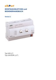
2.5 Operation<br />
Operation<br />
The functionality and the appearance of the monitor desktop depends on the programming and<br />
thus varies for each system. The possible elements on a screen page show status information,<br />
provide values of other information or are programmed for operation (see picture 4).<br />
(16) Status line<br />
(17) Screen page<br />
(18) Operating or display element<br />
(19) Scroll bar<br />
(20) Function keys<br />
Order-No. 7574 00 1X<br />
picture 4: Monitor elements<br />
Sensoric surface (touch screen)<br />
The monitor possesses a sensoric surface, also know as a touch screen. The device is operated<br />
by touching the monitor surface with your finger or with special touch screen pens (not<br />
contained in the scope of supply).<br />
i Do not use sharp objects for operation. The surface may be damaged and thus operation<br />
impeded.<br />
Status line<br />
When configured in the ETS, the status line (16) can be seen on the top edge of the screen.<br />
The status line can display up to ten elements of the following functions...<br />
- Event display<br />
- Collective fault message<br />
- Value display<br />
- Date<br />
- Time<br />
- ASCII text<br />
Screen page<br />
Fitting, electrical connection and operation<br />
Operating and display elements (18) are displayed on the screen pages (17)...<br />
- Display elements display the statuses of components (e.g. lighting systems, heating or air<br />
conditioning systems, shading controls).<br />
Page 12 of 222
- Operating elements are used for navigation or symbolise devices, components and functions<br />
to be controlled.<br />
- Wallpapers can be stored on any screen page.<br />
Function keys<br />
There are a maximum of four function buttons (20) available for each operating element (18),<br />
which can be displayed and operated after selecting the operating element. You can configure<br />
in the ETS whether the function buttons for an operating element are visible on the screen or<br />
not.<br />
Order-No. 7574 00 1X<br />
Fitting, electrical connection and operation<br />
Page 13 of 222
3 Technical data<br />
General<br />
Mark of approval KNX / EIB<br />
Storage/transport temperature -25 ... +75 °C (Storage above + +45 °C reduces<br />
the lifetime.)<br />
Ambient temperature -5 ... +45 °C<br />
Fixing type Installation in Flush-mounted box (e.g. small<br />
distribution board, etc.)<br />
Dimensions WxHxD approx. 220x140x48mm (without design frame)<br />
Terminals for mains supply<br />
Connection mode Screw terminal<br />
single stranded 0.5 ... 2.5 mm²<br />
finely stranded with conductor sleeve 0.5 ... 1.5 mm²<br />
finely stranded without conductor sleeve 0.5 ... 2.5 mm²<br />
External supply<br />
Rated voltage AC 230 V ~<br />
Mains frequency 50 / 60 Hz<br />
Power consumption approx. 13.8 W<br />
Standby power approx. 5 W<br />
KNX / EIB supply<br />
KNX medium TP 1<br />
Commissioning mode S mode<br />
Rated voltage KNX DC 21 V ... 32 V SELV<br />
Current consumption KNX max. 10 mA<br />
Connection mode KNX Terminal<br />
USB<br />
Number 1<br />
Version: 2.0<br />
Connection Type B<br />
Ethernet<br />
Number 1<br />
Type 10 MBit/s Ethernet<br />
Connection RJ45-socket 8/4-pin<br />
Protocols TCP/IP, IMAPv4, POP3, SMTP<br />
DHCP possible (set to active at the factory), AutoIP<br />
Internal clock module (RTC)<br />
Power reserve min. 12 hours<br />
Rate deviation
4 Software description<br />
4.1 Software specification<br />
ETS search paths: Displays / Tableau / <strong>Master</strong> <strong>Control</strong><br />
BAU used: TPUART + µC<br />
KNX/EIB type class: 3g device with cert. PhL + stack + µC<br />
Configuration: S mode with plug-in<br />
PEI type: "0A"Hex / "10" Dec<br />
PEI connector: No connector<br />
Application program:<br />
No. Short description Name Version from screen<br />
version<br />
1 Panel with coloured touch display. <strong>Master</strong> <strong>Control</strong><br />
590101<br />
Order-No. 7574 00 1X<br />
Software specification<br />
0.1 701<br />
Page 15 of 222
4.2 Software "...590101"<br />
4.2.1 Scope of functions<br />
Scope of functions<br />
- The panel is used to control building functions and to display building statuses of various<br />
features.<br />
- The panel can be used both in landscape format and in portrait format. The selected installation<br />
position is entered in the project planning software (ETS plug-in). The space for arranging<br />
the display elements is dependent on this.<br />
- Image files in BMP or JPG format can be included as a background, a display icon or<br />
status display. Eight configurable colour schemes allow adaptation of the graphic display.<br />
- Up to 400 display elements can be shown on up to 50 freely-programmable screen pages.<br />
Each page can display up to 16 display elements. The screen pages can be selected and<br />
displayed using a separate KNX/EIB communication object.<br />
- A scrollbar allows navigation between the screen pages and the display elements contained<br />
within.<br />
- Up to four function buttons can be allocated to each display element. These function buttons<br />
can be directly linked to the function of a display element or can trigger independent<br />
functions. Independent functions include: switching, dimming, blinds, value, light scene, restraints,<br />
DALI error status. In addition, you can use the function buttons to navigate<br />
between screen pages.<br />
- The display elements can be configured to the functions switching, dimming, blinds, value<br />
display with various variables, light scene control, date, time, text display, datalogger display,<br />
access check, restraint, operating mode switch of a heating/cooling system, collective<br />
feedback or load type of a dimmer actuator.<br />
- The panel possesses an Ethernet interface. Various embedded IP protocols allow up to five<br />
synchronised and password-protected mailboxes and thus the text contents of e-mails to<br />
be opened and written.<br />
- Display of up to eight RSS newsfeeds (RSS 2.0) in colour on the panel display.<br />
- The display and operating functions of the panel can be visualised 'from a distance' using<br />
easy-to-install PC Client software and can be operated (remote communication). The Ethernet<br />
interface also permits user-orientated configuration and commissioning of the panel.<br />
- Four password levels allow protection against unauthorised access to the screen pages or<br />
e-mail mailboxes.<br />
- There is a weekly timer switch with up to 16 channels. The individual channels can be used<br />
for different functions (switching, values, light scenes, operating mode switching). A random<br />
and an astro function can be activated optionally on each timer switch channel. The<br />
switching times are programmed in the ETS or directly on the panel after commissioning.<br />
Order-No. 7574 00 1X<br />
Software "...590101"<br />
Scope of functions<br />
Page 16 of 222
- Up 24 light scenes with a total of 32 actuator groups can be created. The light scenes are<br />
set directly on the panel after commissioning.<br />
- There are up to 80 logical links available, each with up to 8 inputs, up to 12 multiplexers<br />
each with up to three channels and 40 timers with ON delay and OFF delay and a filter<br />
function.<br />
- Up to 50 different fault messages can be used. Of these fault messages, up to 20 can be<br />
active simultaneously. Activation, acknowledgement and deactivation of fault messages<br />
can be logged in a message list.<br />
- A synchronisable real-time clock is available for setting up time switch functions and for<br />
logging events. The events can be forwarded by a switching command using predefined emails.<br />
- A presence simulation allows the recording or playing back of any simulations over specific<br />
periods of time.<br />
- A datalogger provides the option of recording data, received from the KNX/EIB, in various<br />
formats, and displaying them on the unit. The data recorded by the datalogger can also be<br />
forwarded by e-mail.<br />
- If necessary, a signalling system can provide a security-orientated system to monitor doors<br />
and windows. Up to two different signalling areas (internal / external) can be armed and<br />
monitored for break-ins and sabotage. Thus visual and acoustic alarming is possible using<br />
additional KNX/EIB components (e.g. switching actuators) in conjunction with alarm encoders<br />
(flash light, internal siren).<br />
- Project planning takes places with an ETS plug-in. Commissioning can take place both via<br />
the ETS and via the plug-in. Programming via the plug-in can save considerable time on<br />
account of the access to the internal USB interface of the panel.<br />
Order-No. 7574 00 1X<br />
Software "...590101"<br />
Scope of functions<br />
Page 17 of 222
4.2.2 Software information<br />
Information on configuration and commissioning<br />
The ETS application described in this documentation and carrying the number "...5901 0.1" including<br />
the plug-in is used to configure the device with the <strong>Berker</strong> order no. 7574 00 12 or 7574<br />
00 13 (<strong>Master</strong> <strong>Control</strong> with Ethernet interface).<br />
The so-called application can also be programmed in older device variants<br />
(Minipanel MT 701 ct / <strong>Berker</strong> order no. 7574 00 10 or 7574 00 11). In this case, the firmware in<br />
the old device must be updated. This update is carried out automatically by the plug-in after a<br />
user confirmation. In this way, updated old devices can have the functionality of the new firmware.<br />
Only the IP functionality (remote operation, e-mail, RSS feeds, etc.) is not available due to<br />
the fact that there is no Ethernet interface in the old devices.<br />
The firmware makes the following functions available:<br />
- Presence simulation<br />
- Signalling system<br />
- Datalogger<br />
- Timer switch: astro and random function, preconfiguration of the switching times in the ETS<br />
plug-in<br />
- Static icons for display elements<br />
- Extended positioning parameters for display elements<br />
- Display functions, collective feedback and dimmer actuator load type<br />
- Internal clock: <strong>Master</strong> function<br />
- Open page via object<br />
- Character sets can be selected for user pages<br />
Device variants older than those above cannot be programmed using the application and the<br />
plug-in described in this documentation.<br />
Plug-in project planning data of older device variants - for example from existing ETS projects -<br />
can be inserted into the ETS plug-in of newer devices via a template export and import and then<br />
extended as required according to the new functionality. It is not possible to transport templates<br />
from the application of newer devices into the plug-in of older ones.<br />
Order-No. 7574 00 1X<br />
Software "...590101"<br />
Software information<br />
Page 18 of 222
4.2.3 Object table<br />
Number of communication objects: max. 2,000<br />
Generated dynamically<br />
Number of addresses (max): 3,000<br />
Number of assignments (max): 3,000<br />
Dynamic table management: No<br />
Maximum table length: ----<br />
The communication objects are generated dynamically by the ETS plugin according to<br />
requirements. Within the ETS (Project view) all the objects described below are displayed<br />
as collective objects with allocated group addresses, depending on the data format.<br />
Group addresses may only be linked to communication objects in the plug-in.<br />
Objects for general functions<br />
Function: Acoustic signal<br />
Object<br />
h<br />
Function<br />
Sound output<br />
Order-No. 7574 00 1X<br />
Name<br />
Acoustic signal<br />
Type<br />
1 bit<br />
DP type<br />
1,001<br />
Description 1 bit object, using which the piezo buzzer can be switched on and off. If this<br />
object is used, all the automatic signal tones (e.g. for fault messages) are suppressed..<br />
0 = Buzzer off / 1 = Buzzer on<br />
Function: Automatic time setting<br />
Object<br />
h<br />
Function<br />
Date / Time<br />
Name<br />
Automatic time<br />
setting<br />
Type<br />
1 bit<br />
DP type<br />
1,001<br />
Description 1 bit object, via which the summer / winter time setting can be carried via the<br />
bus.<br />
0 = Winter time / 1 = Summer time<br />
Function: Display lighting<br />
Object<br />
h<br />
Function<br />
LCD lighting<br />
Name<br />
Lighting object<br />
Type<br />
1 bit<br />
Software "...590101"<br />
DP type<br />
1,001<br />
Object table<br />
Description 1 bit object, using which the display background lighting can be switched off<br />
and on. The telegram polarity can be configured.<br />
After a time settable in the plug in has elapsed, the lighting automatically<br />
switches back to the basic level of brightness.<br />
Flag<br />
C, S<br />
Flag<br />
C, S<br />
Flag<br />
C, S<br />
Page 19 of 222
Function: Date / time request<br />
Object<br />
h<br />
Function<br />
Request<br />
Order-No. 7574 00 1X<br />
Name<br />
Request date /<br />
time<br />
Type<br />
1 bit<br />
DP type<br />
1,001<br />
Description 1 bit object, using which a request telegram for the data and time on the KNX/<br />
EIB can be transmitted (depending on parameters). In this way, the panel can<br />
poll the date and current time from another bus subscriber, e.g. <strong>Master</strong> clock.<br />
The response of the master is then expected via the objects "<strong>Master</strong>Date" and<br />
"<strong>Master</strong>Time".<br />
The request is made after a restart and then every night at 4.00 am. The telegram<br />
polarity can be configured.<br />
Function: Date<br />
Object<br />
h<br />
Function<br />
Transmit<br />
Name<br />
Date object<br />
Type<br />
3 byte<br />
DP type<br />
11,001<br />
Flag<br />
C, T<br />
Flag<br />
C, W, T<br />
Description 3 byte object with which the panel can send the internal date to the bus cyclically<br />
or on request.<br />
Function: <strong>Master</strong> clock date<br />
Object<br />
h<br />
Function<br />
External comparison<br />
Name<br />
<strong>Master</strong> date<br />
Type<br />
3 byte<br />
DP type<br />
11,001<br />
Flag<br />
C, W, T<br />
Description 3 byte object, with which the panel can receive the current date from a KNX/<br />
EIB master clock for synchronisation (parameter-dependent).<br />
Function: <strong>Master</strong> clock time<br />
Object<br />
h<br />
Function<br />
External comparison<br />
Name<br />
<strong>Master</strong> time<br />
Type<br />
3 byte<br />
DP type<br />
10,001<br />
Flag<br />
C, W, T<br />
Description 3 byte object, with which the panel can receive the current time from a KNX/<br />
EIB master clock for synchronisation (parameter-dependent). The weekday information<br />
can also be obtained from the time telegram.<br />
Function: Time<br />
Object<br />
h<br />
Function<br />
Transmit<br />
Name<br />
Time object<br />
Type<br />
3 byte<br />
Software "...590101"<br />
DP type<br />
10,001<br />
Object table<br />
Flag<br />
C, W, T<br />
Description 3 byte object with which the panel can send the internal time to the bus cyclically<br />
or on request. The weekday information can also be transmitted with the<br />
time telegram.<br />
Page 20 of 222
Function: Date / time request by external device<br />
Object<br />
h<br />
Function<br />
Date / Time<br />
Order-No. 7574 00 1X<br />
Name<br />
Request date /<br />
time by external<br />
device<br />
Type<br />
1 bit<br />
DP type<br />
1,001<br />
Description 1 bit object, using which the panel can receive a request telegram from another<br />
KNX/EIB subscriber (depending on parameters). The panel responds to an<br />
external poll by transmitting the data and/or time telegram via the "Date object"<br />
and "Time object" objects. You can use the plug-in to configure which of<br />
these telegrams is sent. The telegram polarity of the external poll telegram can<br />
be configured.<br />
Function: Open page<br />
Object<br />
h<br />
Function<br />
General<br />
Name<br />
Open page<br />
Type<br />
1 byte<br />
Flag<br />
C, S<br />
DP type Flag<br />
C, W, T<br />
Description 1 byte object, allowing direct opening of specifically-created pages and optionally<br />
all system pages. An opened page immediately appears on the device display.<br />
Each page can be opened individually using an allocated telegram value.<br />
An overview of all the telegram values can be seen in the chapter "Function<br />
description" of this documentation.<br />
Object for display elements and/or function buttons and for the timer switch (only partially)<br />
Function: Switching function<br />
Object<br />
h<br />
Function<br />
Switching<br />
Name<br />
Switching object<br />
Type<br />
1 bit<br />
Description 1 bit object to transmit and receive switching telegrams<br />
Function: Dimming functions<br />
Object<br />
h<br />
Function<br />
Dimming<br />
Name<br />
Switching object<br />
Type<br />
1 bit<br />
Description 1 bit object to transmit and receive switching telegrams<br />
Function: Dimming functions<br />
Object<br />
h<br />
Function<br />
Dimming<br />
Name<br />
Dimming object<br />
Type<br />
4 bit<br />
Software "...590101"<br />
DP type<br />
1,001<br />
DP type<br />
1,001<br />
DP type<br />
3,007<br />
Object table<br />
Flag<br />
C, W, T<br />
Flag<br />
C, W, T<br />
Flag<br />
C, W, T<br />
Description 4-bit object to transmit and receive dimming telegrams for relative dimming.<br />
Page 21 of 222
Function: Dimming functions<br />
Object<br />
h<br />
Function<br />
Dimming<br />
Order-No. 7574 00 1X<br />
Name<br />
Value object<br />
Type<br />
1 byte<br />
DP type<br />
5,001<br />
Flag<br />
C, W, T<br />
Description 1 byte object to transmit and receive value telegrams. These values can be<br />
displayed either as numeric values (0 ... 255) or as percentages (0 ... 100%).<br />
Function: Blind/roller shutter control function<br />
Object<br />
h<br />
Function<br />
Blind<br />
Name<br />
Long-time object<br />
Type<br />
1 bit<br />
DP type<br />
1,008<br />
Flag<br />
C, W, T<br />
Description 1 bit object for moving (long-time operation) roller blinds and similar drives.<br />
Function: Blind/roller shutter control function<br />
Object<br />
h<br />
Function<br />
Blind<br />
Name<br />
Short-time object<br />
Type<br />
1 bit<br />
DP type<br />
1,007<br />
Flag<br />
C, W, T<br />
Description 1 bit object for stopping and stepped adjustment (short-time operation) of<br />
blinds and similar drives.<br />
Function: Value function<br />
Object<br />
h<br />
Function<br />
Value<br />
Name<br />
2 byte object (DPT<br />
9,001 … 9,021)<br />
Type<br />
2 byte<br />
Description 2 byte object to transmit and receive floating values.<br />
Function: Value function<br />
Object<br />
h<br />
Function<br />
Value<br />
Name<br />
1 byte object (DPT<br />
5,001 … 5,004)<br />
Type<br />
1 byte<br />
DP type<br />
9,001…<br />
9,021<br />
DP type<br />
5,001…<br />
5,004<br />
Flag<br />
C, W, T<br />
Flag<br />
C, W, T<br />
Description 1 byte object to transmit and receive values. These values can be displayed or<br />
specified either as numeric values (0 ... 255), as percentages (0 ... 100%) or<br />
as angles (0 ... 360°).<br />
Function: Value function<br />
Object<br />
h<br />
Function<br />
Value<br />
Name<br />
4 byte object (DPT<br />
14,000 … 14,079)<br />
Type<br />
4 byte<br />
Description 4 byte object to transmit and receive floating values.<br />
Software "...590101"<br />
DP type<br />
14,000<br />
…14,079<br />
Object table<br />
Flag<br />
C, W, T<br />
Page 22 of 222
Function: Value function<br />
Object<br />
h<br />
Function<br />
Value<br />
Order-No. 7574 00 1X<br />
Name<br />
2 byte object (DPT<br />
7,001)<br />
Type<br />
2 byte<br />
DP type<br />
7,001<br />
Flag<br />
C, W, T<br />
Description 2 byte object to transmit and receive counter values. The received value can<br />
be adapted to the required format before being displayed.<br />
Function: Value function<br />
Object<br />
h<br />
Function<br />
Value<br />
Name<br />
2 byte object (DPT<br />
8,001)<br />
Type<br />
2 byte<br />
DP type<br />
8,001<br />
Flag<br />
C, W, T<br />
Description 2 byte object to transmit and receive counter values. The received value can<br />
be adapted to the required format before being displayed.<br />
Function: Value function<br />
Object<br />
h<br />
Function<br />
Value<br />
Name<br />
4 byte object (DPT<br />
12,001)<br />
Type<br />
4 byte<br />
DP type<br />
12,001<br />
Flag<br />
C, W, T<br />
Description 4 byte object to transmit and receive counter values. The received value can<br />
be adapted to the required format before being displayed.<br />
Function: Value function<br />
Object<br />
h<br />
Function<br />
Value<br />
Name<br />
4 byte object (DPT<br />
13,001)<br />
Type<br />
4 byte<br />
DP type<br />
13,001<br />
Flag<br />
C, W, T<br />
Description 4 byte object to transmit and receive counter values. The received value can<br />
be adapted to the required format before being displayed.<br />
Function: Value function<br />
Object<br />
h<br />
Function<br />
Value<br />
Name<br />
1 byte object (DPT<br />
5,010)<br />
Type<br />
1 byte<br />
DP type<br />
5,010<br />
Flag<br />
C, W, T<br />
Description 1 byte object to transmit and receive counter values. The received value can<br />
be adapted to the required format before being displayed.<br />
Function: Value function<br />
Object<br />
h<br />
Function<br />
Value<br />
Name<br />
1 byte object (DPT<br />
6,010)<br />
Type<br />
1 byte<br />
Software "...590101"<br />
DP type<br />
6,010<br />
Object table<br />
Flag<br />
C, W, T<br />
Description 1 byte object to transmit and receive counter values. The received value can<br />
be adapted to the required format before being displayed.<br />
Page 23 of 222
Function: Limit value function<br />
Object<br />
h<br />
Function<br />
Value<br />
Order-No. 7574 00 1X<br />
Name<br />
Object top limit<br />
value<br />
Type<br />
1 bit<br />
DP type<br />
1,001<br />
Description 1 bit object to transmit a limit value telegram, if the corresponding value object<br />
exceeds or undershoots the defined limit value.<br />
Function: Limit value function<br />
Object<br />
h<br />
Function<br />
Value<br />
Name<br />
Object bottom limit<br />
value<br />
Type<br />
1 bit<br />
DP type<br />
1,001<br />
Description 1 bit object to transmit a limit value telegram, if the corresponding value object<br />
exceeds or undershoots the defined limit value.<br />
Function: Date display function<br />
Object<br />
h<br />
Function<br />
Date<br />
Name<br />
Date object<br />
Type<br />
3 byte<br />
DP type<br />
11,001<br />
Description 3 byte object to display date information in a display element.<br />
Function: Date display function<br />
Object<br />
h<br />
Function<br />
Time<br />
Name<br />
Time object<br />
Description 3 byte object to display time information.<br />
Function: Text display function<br />
Object<br />
h<br />
Function<br />
ASCII text<br />
Name<br />
ASCII text object<br />
Description 14 byte object to display text information.<br />
Function: Access check function<br />
Object<br />
h<br />
Function<br />
Access check<br />
Name<br />
Access object<br />
Type<br />
3 byte<br />
Type<br />
14 byte<br />
Type<br />
4 byte<br />
Software "...590101"<br />
DP type<br />
10,001<br />
DP type<br />
16,001...<br />
16,002<br />
DP type<br />
15,000<br />
Object table<br />
Description 4 byte object to display the code number or individual parts of the status byte<br />
within an access check.<br />
Flag<br />
C, T<br />
Flag<br />
C, T<br />
Flag<br />
C, S<br />
Flag<br />
C, S<br />
Flag<br />
C, S<br />
Flag<br />
C, S<br />
Page 24 of 222
Function: Restraint function<br />
Object<br />
h<br />
Function<br />
Restraint<br />
Order-No. 7574 00 1X<br />
Name<br />
Switching object<br />
Type<br />
1 bit<br />
DP type<br />
1,001<br />
Flag<br />
C, W, T<br />
Description 1 bit object for transmitting and receiving switching telegrams, which are used<br />
in conjunction with a higher level 2 bit restraint object.<br />
Function: Restraint function<br />
Object<br />
h<br />
Function<br />
Restraint<br />
Name<br />
Restraint object<br />
Type<br />
2 bit<br />
DP type<br />
2,001...<br />
2,002<br />
Flag<br />
C, W, T<br />
Description 2 bit object for transmitting and receiving higher-level restraint control information.<br />
Function: Operating mode display function<br />
Object<br />
h<br />
Function<br />
Operating mode switch<br />
Name<br />
Operating mode<br />
Connex<br />
Type<br />
1 byte<br />
DP type<br />
20,102<br />
Flag<br />
C, W, T<br />
Description 1 byte object to display or switch the operating mode of a room temperature<br />
controller.<br />
Function: Operating mode display function<br />
Object<br />
h<br />
Function<br />
Operating mode switch<br />
Name<br />
Frost/ heat protection<br />
Type<br />
1 bit<br />
DP type<br />
1,001<br />
Flag<br />
C, W, T<br />
Description 1 bit object to display or switch the operating mode of a room temperature<br />
controller.<br />
Function: Operating mode display function<br />
Object<br />
h<br />
Function<br />
Operating mode switch<br />
Name<br />
Comfort-mode<br />
Type<br />
1 bit<br />
DP type<br />
1,001<br />
Flag<br />
C, W, T<br />
Description 1 bit object to display or switch the operating mode of a room temperature<br />
controller.<br />
Function: Operating mode display function<br />
Object<br />
h<br />
Function<br />
Operating mode switch<br />
Name<br />
Night reduction<br />
Type<br />
1 bit<br />
Software "...590101"<br />
DP type<br />
1,001<br />
Object table<br />
Flag<br />
C, W, T<br />
Description 1 bit object to display or switch the operating mode of a room temperature<br />
controller.<br />
Page 25 of 222
Function: Operating mode display function<br />
Object<br />
h<br />
Function<br />
Operating mode switch<br />
Order-No. 7574 00 1X<br />
Name<br />
Standby<br />
Type<br />
1 bit<br />
DP type<br />
1,001<br />
Flag<br />
C, W, T<br />
Description 1 bit object to display or switch the operating mode of a room temperature<br />
controller.<br />
Function: Display function for collective feedback<br />
Object<br />
h<br />
Function<br />
Collective feedback<br />
Name<br />
Collective feedback<br />
Type<br />
4 byte<br />
DP type<br />
27,001<br />
Description 4 byte object to evaluate and display the switching state of a specific switching<br />
output of an actuator supporting collective feedback. The switching output to<br />
be evaluated in the collective feedback telegram is configured in the plug-in.<br />
Function: Display function for dimmer actuator load type<br />
Object<br />
h<br />
Function<br />
Dimmer actuator load type<br />
Name<br />
Dimmer actuator<br />
load type<br />
Type<br />
1 byte<br />
DP type<br />
20,xxx<br />
Description 1 byte object to display the connected load type of a dimmer actuator channel.<br />
Objects for status elements in the status line<br />
Function: Display function for status elements<br />
Object<br />
h<br />
Function<br />
Event display<br />
Name<br />
Switching object<br />
Description 1 bit object to display information in the status line.<br />
Objects for the fault message function<br />
Function: Fault message<br />
Object<br />
h<br />
Function<br />
Fault message<br />
Name<br />
Ackowledgement<br />
object<br />
Description 1 bit object to confirm a received fault message.<br />
Type<br />
1 bit<br />
Type<br />
1 bit<br />
Software "...590101"<br />
DP type<br />
1,001<br />
DP type<br />
1,001<br />
Object table<br />
Flag<br />
C, S<br />
Flag<br />
C, S<br />
Flag<br />
C, W, T<br />
Flag<br />
C, T<br />
Page 26 of 222
Function: Fault message<br />
Object<br />
h<br />
Function<br />
Fault message<br />
Order-No. 7574 00 1X<br />
Name<br />
Fault signal object<br />
Description 1 bit object to receive a fault message.<br />
Function: Fault message<br />
Object<br />
h<br />
Function<br />
Fault message<br />
Name<br />
Acknowledgement<br />
reception object<br />
Type<br />
1 bit<br />
Type<br />
1 bit<br />
DP type<br />
1,001<br />
DP type<br />
1,001<br />
Description 1 bit object via which acknowledgements of other devices can be received.<br />
Function: Fault message<br />
Object<br />
h<br />
Function<br />
Fault message<br />
Name<br />
ASCII text object<br />
Type<br />
14 byte<br />
DP type<br />
16,001...<br />
16,002<br />
Description 14 byte object to display a variable message text with a fault message activated.<br />
Objects for the timers<br />
Function: Timer<br />
Object<br />
h<br />
Function<br />
Timer<br />
Name<br />
Start object<br />
Type<br />
1 bit<br />
DP type<br />
1,001<br />
Description 1 bit object which forwards the logical switching state of the timer output.<br />
Function: Timer<br />
Object<br />
h<br />
Function<br />
Timer<br />
Name<br />
Input object<br />
Type<br />
1 bit<br />
Software "...590101"<br />
DP type<br />
1,001<br />
Object table<br />
Description 1 bit object, whose value is forwarded to the output object of the timer, depending<br />
on the value of the appropriate blocking object, the set filter function<br />
and the defined delays.<br />
Flag<br />
C, S<br />
Flag<br />
C, S<br />
Flag<br />
C, S<br />
Flag<br />
C, T<br />
Flag<br />
C, S<br />
Page 27 of 222
Function: Timer<br />
Object<br />
h<br />
Function<br />
Timer<br />
Order-No. 7574 00 1X<br />
Name<br />
Blocking object<br />
Type<br />
1 bit<br />
DP type<br />
1,001<br />
Description 1 bit object which specifies whether the value of the corresponding input object<br />
is forwarded to the output object. The behaviour of the blocking object can<br />
be set.<br />
Objects for logic gate<br />
Function: Logic gate<br />
Object<br />
h<br />
Function<br />
Logic gate<br />
Name<br />
Blocking object<br />
Type<br />
1 bit<br />
DP type<br />
1,001<br />
Description 1 bit object which specifies whether the value of the output object of the logic<br />
gate can be transmitted.<br />
Function: Logic gate<br />
Object<br />
h<br />
Function<br />
Logic gate<br />
Name<br />
Input object<br />
Type<br />
1 bit<br />
DP type<br />
1,001<br />
Description 1 bit objects, which can be logically linked to each other. Each input object of a<br />
logic gate can be processed either normally or inverted.<br />
Function: Logic gate<br />
Object<br />
h<br />
Function<br />
Logic gate<br />
Name<br />
Start object<br />
Type<br />
1 bit<br />
DP type<br />
1,001<br />
Flag<br />
C, S<br />
Flag<br />
C, S<br />
Flag<br />
C, S<br />
Flag<br />
C, W, T, R<br />
Description 1 bit object, which outputs the result of the logical link. The type of link (AND,<br />
OR, EXCLUSIVE OR, AND with return), the behaviour (normal or inverted)<br />
and the transmit criterion (transmit on any input event or send on changing the<br />
output) can be set.<br />
Objects for multiplexers<br />
Function: Multiplexer<br />
Object<br />
h<br />
Function<br />
Multiplexer<br />
Name<br />
Blocking object<br />
Type<br />
1 bit<br />
Software "...590101"<br />
DP type<br />
1,001<br />
Object table<br />
Description 1 bit object which specifies whether the value of the active output object of the<br />
multiplexer can be transmitted.<br />
Flag<br />
C, S<br />
Page 28 of 222
Function: Multiplexer<br />
Object<br />
h<br />
Function<br />
Multiplexer<br />
Order-No. 7574 00 1X<br />
Name<br />
<strong>Control</strong> object ...<br />
Type<br />
1 bit<br />
DP type<br />
1,001<br />
Description 1 bit object which specifies to which output object the value of the corresponding<br />
input object is forwarded.<br />
Function: Multiplexer<br />
Object<br />
h<br />
Function<br />
Multiplexer<br />
Name<br />
<strong>Control</strong> object ...<br />
Type<br />
1 bit<br />
DP type<br />
1,001<br />
Description 1 bit object which specifies to which output object the value of the corresponding<br />
input object is forwarded.<br />
Two control objects may be visible, depending on the configured function (1 to<br />
2 multiplexers or 1 to 4 multiplexers).<br />
Function: Multiplexer<br />
Object<br />
h<br />
Function<br />
Multiplexer<br />
Name<br />
Input object<br />
Type<br />
1 bit<br />
4 bit<br />
1 byte<br />
2 byte<br />
4 byte<br />
Software "...590101"<br />
DP type<br />
1,001…<br />
1,008<br />
3,007<br />
5,001...<br />
5,004<br />
5,010<br />
6,010<br />
7,001<br />
8,001<br />
9,001...<br />
9,021<br />
12,001<br />
13,001<br />
14,000...<br />
14,079<br />
Object table<br />
Description Object with adjustable type, who value is forwarded to one of two or four output<br />
objects according to one or control objects.<br />
Flag<br />
C, S<br />
Flag<br />
C, S<br />
Flag<br />
C, S<br />
Page 29 of 222
Function: Multiplexer<br />
Object<br />
h<br />
Function<br />
Multiplexer<br />
Order-No. 7574 00 1X<br />
Name<br />
Start object<br />
Type<br />
1 bit<br />
4 bit<br />
1 byte<br />
2 byte<br />
4 byte<br />
DP type<br />
1,001…<br />
1,008<br />
3,007<br />
5,001...<br />
5,004<br />
5,010<br />
6,010<br />
7,001<br />
8,001<br />
9,001...<br />
9,021<br />
12,001<br />
13,001<br />
14,000...<br />
14,079<br />
Description One of two or one of four output objects receiving the value of the input object.<br />
Objects for datalogger<br />
Function: Datalogger<br />
Object<br />
h<br />
Function<br />
Datalogger channel<br />
Name<br />
<br />
Type<br />
1 bit<br />
4 bit<br />
1 byte<br />
2 byte<br />
4 byte<br />
Software "...590101"<br />
DP type<br />
1,001…<br />
1,008<br />
3,007<br />
5,001...<br />
5,004<br />
5,010<br />
6,010<br />
7,001<br />
8,001<br />
9,001...<br />
9,021<br />
12,001<br />
13,001<br />
14,000...<br />
14,079<br />
Object table<br />
Flag<br />
C, T<br />
Flag<br />
C, W, T<br />
Description Object with settable type, whose value is recorded by the panel at settable<br />
times and which can be displayed in a display element as a datalogger channel<br />
as a diagram on the screen.<br />
Page 30 of 222
Objects for presence simulation<br />
Function: Presence simulation<br />
Object<br />
h<br />
Function<br />
Status<br />
Order-No. 7574 00 1X<br />
Name<br />
Play active<br />
Type<br />
1 bit<br />
DP type<br />
1,001<br />
Description 1 bit object, which displays that a presence simulation is being played.<br />
0 = Presence simulation not being played / 1 = Presence simulation being<br />
played.<br />
Function: Presence simulation<br />
Object<br />
h<br />
Function<br />
Status<br />
Name<br />
Recording active<br />
Type<br />
1 bit<br />
DP type<br />
1,001<br />
Description 1 bit object, which displays that a presence simulation is being recorded.<br />
0 = Presence simulation not being recorded / 1 = Presence simulation being<br />
recorded.<br />
Function: Presence simulation<br />
Object<br />
h<br />
Function<br />
Presence simulation<br />
Name<br />
Start/stop playing<br />
Type<br />
1 bit<br />
DP type<br />
1,001<br />
Description 1 bit object, with which the playback of a presence situation can be started<br />
and stopped.<br />
0 = Stop presence simulation / 1 = Start presence simulation.<br />
Function: Presence simulation<br />
Object<br />
h<br />
Function<br />
Recording object<br />
Name<br />
<br />
Type<br />
1 bit<br />
1 byte<br />
Software "...590101"<br />
DP type<br />
1,001<br />
5,001...<br />
5,010<br />
6,001<br />
Object table<br />
Flag<br />
C, T<br />
Flag<br />
C, T<br />
Flag<br />
C, S<br />
Flag<br />
C, W, T<br />
Description Object with adjustable type (1 bit or 1 byte), whose received telegram values<br />
can be saved by time by the panel during a recording. The recorded telegrams<br />
can later be transmitted when playing back on the bus.<br />
Page 31 of 222
Object for e-mail mailboxes<br />
Function: e-mail<br />
Object<br />
h<br />
Function<br />
e-mail<br />
Order-No. 7574 00 1X<br />
Name<br />
Mailbox 1...5: new<br />
e-mail<br />
Type<br />
1 bit<br />
DP type<br />
1,001<br />
Description 1 bit object to signal whether there is a new, unread e-mail in one of up to five<br />
e-mail mailboxes. Each mailbox has its own object.<br />
0 = No new e-mail available / 1 = New e-mail available.<br />
Function: e-mail<br />
Object<br />
h<br />
Function<br />
e-mail<br />
Name<br />
Send e-mail<br />
Type<br />
1 bit<br />
DP type<br />
1,001<br />
Description 1 bit object, with which an e-mail predefined in the ETS can be sent.<br />
The telegram polarity can be configured.<br />
Objects for signalling system<br />
Function: Signalling system<br />
Object<br />
h<br />
Function<br />
Signalling system input<br />
Name<br />
Internally armed,<br />
external skin monitoring<br />
Type<br />
1 bit<br />
DP type<br />
1,001<br />
Description 1 bit object to arm and unarm the external skin monitoring (internally armed).<br />
0 = Unarm / 1 = Arm<br />
Function: Signalling system<br />
Object<br />
h<br />
Function<br />
Signalling system input<br />
Name<br />
Externally armed,<br />
internal and external<br />
skin monitoring<br />
Type<br />
1 bit<br />
Software "...590101"<br />
DP type<br />
1,001<br />
Object table<br />
Description 1 bit object to arm and unarm the internal and external skin monitoring (externally<br />
armed).<br />
0 = Unarm / 1 = Arm<br />
Flag<br />
C, T<br />
Flag<br />
C, S<br />
Flag<br />
C, S<br />
Flag<br />
C, S<br />
Page 32 of 222
Function: Signalling system<br />
Object<br />
h<br />
Function<br />
Signalling system input<br />
Order-No. 7574 00 1X<br />
Name<br />
Sabotage<br />
Type<br />
1 bit<br />
DP type<br />
1,001<br />
Description 1 bit object as a sabotage of the signalling system. The sabotage detector can<br />
be connected to this object.<br />
0 = No sabotage, detector inactive / 1 = Sabotage, detector active<br />
Function: Signalling system<br />
Object<br />
h<br />
Function<br />
Signalling system output<br />
Name<br />
Ready to arm, internal<br />
Type<br />
1 bit<br />
DP type<br />
1,001<br />
Description 1 bit object to signal that the signalling system is internally ready to arm. The<br />
system is only internally ready to arm when none of the detectors allocated to<br />
the external skin is active and there is no fault.<br />
0 = Not ready to arm / 1 = Ready to arm<br />
Function: Signalling system<br />
Object<br />
h<br />
Function<br />
Signalling system output<br />
Name<br />
Ready to arm, external<br />
Type<br />
1 bit<br />
DP type<br />
1,001<br />
Description 1 bit object to signal that the signalling system is externally ready to arm. The<br />
system is only externally ready to arm when none of the detectors allocated to<br />
the internal skin and the external skin is active and there is no fault.<br />
0 = Not ready for arming / 1 = Ready for arming<br />
Function: Signalling system<br />
Object<br />
h<br />
Function<br />
Signalling system output<br />
Name<br />
Alarm<br />
Description 1 bit object to signal a break-in or sabotage alarm.<br />
0 = No alarm / 1 = Alarm<br />
Function: Signalling system<br />
Object<br />
h<br />
Function<br />
Signalling system output<br />
Name<br />
Arming message,<br />
internal<br />
Type<br />
1 bit<br />
Type<br />
1 bit<br />
Software "...590101"<br />
DP type<br />
1,001<br />
DP type<br />
1,001<br />
Object table<br />
Description 1 bit object for static signalling that the signalling system has successfully<br />
armed internally, i.e. the external skin monitoring is active.<br />
0 = External skin monitoring not armed / 1 = External skin monitoring armed<br />
Flag<br />
C, S<br />
Flag<br />
C, T<br />
Flag<br />
C, T<br />
Flag<br />
C, T<br />
Flag<br />
C, T<br />
Page 33 of 222
Function: Signalling system<br />
Object<br />
h<br />
Function<br />
Signalling system output<br />
Order-No. 7574 00 1X<br />
Name<br />
Arming message,<br />
external<br />
Type<br />
1 bit<br />
DP type<br />
1,001<br />
Description 1 bit object for static signalling that the signalling system has successfully<br />
armed externally, i.e. the internal ad external skin monitoring is active.<br />
0 = Internal/external skin monitoring not armed / 1 = Internal/external skin<br />
monitoring armed<br />
Function: Signalling system<br />
Object<br />
h<br />
Function<br />
Signalling system output<br />
Name<br />
Optical signal encoder<br />
Type<br />
1 bit<br />
DP type<br />
1,001<br />
Description 1 bit object to control an optical alarm, e.g. flashlight. If there is an alarm (only<br />
with external arming), signalling is carried out via this alarm output. In addition,<br />
with external arming, an acknowledgement can be given by the optical alarm<br />
encoder (parameter-dependent).<br />
0 = No alarm, flashlight off / 1 = Alarm, flashlight on<br />
Function: Signalling system<br />
Object<br />
h<br />
Function<br />
Signalling system output<br />
Name<br />
Internal siren<br />
Type<br />
1 bit<br />
DP type<br />
1,001<br />
Description 1 bit object to control an acoustic alarm, e.g. internal siren. If there is an alarm<br />
(internal or external arming), signalling is carried out via this alarm output. If<br />
there is an alarm, control of this alarm output is restricted to a certain period of<br />
time. This time can be parameterised in the ETS.<br />
0 = No alarm, internal siren off / 1 = Alarm, internal siren on<br />
Function: Signalling system<br />
Object<br />
h<br />
Function<br />
Signalling system output<br />
Name<br />
Arming acknowledgement<br />
Type<br />
1 bit<br />
Software "...590101"<br />
DP type<br />
1,001<br />
Object table<br />
Description 1 bit object to signal that the signalling system was armed internally or externally.<br />
The object is dynamic, meaning that it is only "1" for the arming acknowledgment<br />
period specified in the ETS. In the unarmed state or if the arming acknowledgment<br />
time has elapsed, the object value is "0".<br />
For example, appropriate pulse blocking elements can be connected to this<br />
signal output.<br />
Flag<br />
C, T<br />
Flag<br />
C, T<br />
Flag<br />
C, T<br />
Flag<br />
C, T<br />
Page 34 of 222
Function: Signalling system<br />
Object<br />
h<br />
Function<br />
Signalling system output<br />
Order-No. 7574 00 1X<br />
Name<br />
Unarming acknowledgement<br />
Type<br />
1 bit<br />
DP type<br />
1,001<br />
Description 1 bit object to signal that the signalling system was unarmed internally or externally.<br />
The object is dynamic, meaning that it is only "1" for the unarming acknowledgment<br />
period specified in the ETS. In the armed state or if the unarming<br />
acknowledgment time has elapsed, the object value is "0".<br />
For example, appropriate pulse blocking elements can be connected to this<br />
signal output.<br />
Function: Signalling system<br />
Object<br />
h<br />
Function<br />
Signalling system output<br />
Name<br />
Fault<br />
Type<br />
1 bit<br />
DP type<br />
1,001<br />
Description 1 bit object for signalling a fault within the signalling system (missing detector,<br />
active sabotage input).<br />
0 = No fault / 1 = Fault.<br />
Function: Signalling system<br />
Object<br />
h<br />
Function<br />
Signalling system output<br />
Name<br />
Alarm detector text<br />
Type<br />
14 byte<br />
DP type<br />
16,001<br />
Description 14 byte object to transfer a 14 character detector text to the bus. If there is an<br />
alarm, the signalling system sends the signal text of the detector triggering the<br />
alarm to the bus via this object. The detector text can be configured separately<br />
for each detector in the ETS.<br />
Function: Signalling system<br />
Object<br />
h<br />
Function<br />
Signalling system output<br />
Name<br />
Fault detector text<br />
Type<br />
14 byte<br />
DP type<br />
16,001<br />
Description 14 byte object to transfer a 14 character detector text to the bus. If there is an<br />
alarm, the signalling system sends the signal text of the detector which caused<br />
the fault (missing detector) to the bus via this object. The detector text can be<br />
configured separately for each detector in the ETS.<br />
Function: Signalling system<br />
Object<br />
h<br />
Function<br />
Signalling system output<br />
Name<br />
Prealarm signalling,<br />
internal<br />
Type<br />
1 bit<br />
Software "...590101"<br />
DP type<br />
1,001<br />
Object table<br />
Description 1 bit object to signal an elapsing prealarm with internal arming. In the case of<br />
previously detected break-in of sabotage alarm, this signal output is "1" for the<br />
length of the alarm delay time configured in the ETS. Otherwise the object<br />
value is "0".<br />
Flag<br />
C, T<br />
Flag<br />
C, T<br />
Flag<br />
C, T<br />
Flag<br />
C, T<br />
Flag<br />
C, T<br />
Page 35 of 222
Function: Signalling system<br />
Object<br />
h<br />
Function<br />
Signalling system output<br />
Order-No. 7574 00 1X<br />
Name<br />
Prealarm signalling,<br />
external<br />
Type<br />
1 bit<br />
DP type<br />
1,001<br />
Description 1 bit object to signal an elapsing prealarm with external arming. In the case of<br />
previously detected break-in of sabotage alarm, this signal output is "1" for the<br />
length of the alarm delay time configured in the ETS. Otherwise the object<br />
value is "0".<br />
Function: Signalling system<br />
Object<br />
h<br />
Function<br />
Signalling system input<br />
Name<br />
Detector<br />
Type<br />
1 bit<br />
DP type<br />
1,001<br />
Flag<br />
C, T<br />
Flag<br />
C, W, T<br />
Description 1 bit object as detector input. There is exactly one detector object for each detector<br />
input for the internal and external skin security areas created in the<br />
ETS. The group address of exactly one KNX/EIB detector is linked to this object.<br />
The telegram polarity of the detector telegram can be configured.<br />
The signalling system cyclically tests the function of a KNX/EIB detector, by<br />
the system transmitting a value read telegram to the bus via the detector object.<br />
The KNX/EIB detector (e.g. the channel of a button interface of a binary<br />
input) must answer the read telegram of the signalling system with a value answer<br />
telegram. For this, the "Read" flag must be set on the communication object<br />
of the KNX/EIB detector.<br />
Object for light scene function<br />
Function: Light scene function<br />
Object<br />
h<br />
Function<br />
Light scenes<br />
Name<br />
Extension object<br />
Description 1 byte object for opening or saving light scenes.<br />
Function: Light scene function<br />
Object<br />
h<br />
Function<br />
Light scene group<br />
Name<br />
Light scene object<br />
Type<br />
1 byte<br />
Type<br />
1 bit<br />
1 byte<br />
Software "...590101"<br />
DP type<br />
18,001<br />
DP type<br />
1,001<br />
5,001...<br />
5,004<br />
Object table<br />
Flag<br />
C, S<br />
Flag<br />
C, W, T<br />
Description 1 bit object or 1 byte object for controlling the actuator group contained in a<br />
light scene.<br />
Page 36 of 222
4.2.4 Functional description<br />
Introduction<br />
The panel allows the display and control of building functions from a central location. To aid display,<br />
there is a freely-programmable, colour TFT display with a resolution of 320x240 pixels. It is<br />
operated via the touchscreen.<br />
The panel allows bidirectional communication with the various data formats via EIB/KNX communication<br />
objects. Both basic functions, such as switching, dimming and blinds, and also complex<br />
functions such as value encoders, date, limit values, etc., can be processed.<br />
The user interface is freely configurable, i.e. the display texts should be matched individually. It<br />
is possible to include wallpapers and icons in the bitmap (bmp) and Joint Photographic Experts<br />
Group (jpg) formats.<br />
The panel is configured and commissioned using an ETS plug-in. During the configuration of<br />
the communications interfaces with other KNX/EIB devices, the ETS plug-in dynamically creates<br />
the required communication objects to all the functions. Therefore, there is no fixed allocation<br />
between individual functions and the numbers of the communication objects. Within the<br />
ETS, centralised objects and all the allocated group addresses are displayed for each projected<br />
data format, so that, if need be, filter tables can be generated by the KNX/EIB area or line<br />
couplers.<br />
4.2.4.1 Basic settings during project planning<br />
Some of the settings made in the ETS plug-in relate to the whole device. This means they may<br />
also influence a larger number of other settings. For example, the following general settings<br />
should be made...<br />
- At the start of project planning, for example, the installation position of the panel, the bus<br />
communication behaviour, the behaviour of the LCD background lighting and the date and<br />
time functionality specified.<br />
- In addition, for first commissioning, the settings relating to download behaviour (behaviour<br />
after a programming operation by the ETS or the plug-in) are important.<br />
- There are eight different colour scheme available to design the individual screen pages and<br />
the elements therein. The colour schemes can be adapted individually.<br />
- The ETS plug-in has a large volume of data to manage, particularly when images are used.<br />
This data can either be saved in the ETS database or in separate files. You can configure<br />
image storage in the panel options.<br />
The settings relevant to the whole device are summarised within the first parameter group of the<br />
ETS plug-in (top parameter node). This parameter group is divided into the subgroups "General",<br />
"LCD lighting", "Date / time" and "Download behaviour".<br />
Start the ETS plug-in by opening the parameter view of the appropriate panel in the ETS project<br />
view.<br />
4.2.4.1.1 General parameters<br />
Installation position<br />
The panel can be used both horizontally, in landscape format, and vertically, in portrait format.<br />
When starting project planning you must accordingly select the installation position of the display<br />
(portrait corresponds to 240 x 320 pixels and landscape to 320 x 240).<br />
Order-No. 7574 00 1X<br />
Software "...590101"<br />
Functional description<br />
Page 37 of 222
Order-No. 7574 00 1X<br />
picture 5: Installation position in landscape format (horizontal)<br />
picture 6: Installation position in portrait format (vertical)<br />
The selected installation position and the available monitor dimensions then apply to the entire<br />
project planning. If the installation position is reconfigured, then all the other panel settings in<br />
the ETS plug-in are lost (deletion of all the pages and all additional settings). For this reason,<br />
the plug-in generates a warning when switching parameters. Only after the warning has been<br />
confirmed do the plug-in change the installation position.<br />
Monitor display<br />
Colour schemes:<br />
To allow easy adjustment of the display element visualisation and, at the same time, an easy to<br />
read display, the ETS plug-in provides eight different colour schemes. The first colour scheme is<br />
fixed. The other seven colour schemes can be changed as required. The "System colour<br />
scheme" parameter in the "General" parameter group specifies the colour scheme for all the<br />
system pages and defines the presetting for each screen page newly created by the project<br />
planning. This higher-level colour scheme is termed "System" in the parameters of each screen<br />
page (see chapter 4.2.4.1.5. Colour schemes).<br />
Scroll bar:<br />
Software "...590101"<br />
Functional description<br />
Page 38 of 222
The individual screen pages and the display elements within a screen page can be arranged<br />
one beneath the other in a specific logic sequence. A scroll bar can be displayed on the right<br />
edge of the screen, using which it is possible to switch between the elements in a forwards and<br />
backwards direction.<br />
- The two double arrows open the previous or the next screen page. You can specify which<br />
pages are jumped to with this navigation in the ETS plug-in.<br />
- Within the current screen pages, the two single arrows activate the next or previous display<br />
element, assuming that multiple display elements can be selected.<br />
If there is no previous or next element defined in the project planning, the appropriate arrow is<br />
automatically deactivated. The "Scroll bar" parameter in the "General" parameter group in the<br />
top parameter node specifies the basic properties of the scroll bar...<br />
- "Always show" setting: the scrollbar can be seen on every screen page. It takes up space,<br />
even if no linked pages are planned.<br />
- "Always hide" setting: the scrollbar cannot be seen on any screen page. In this case, it is<br />
not possible to navigate between the screen pages using the scroll bar.<br />
- "Automatic" setting: the scroll bar is only shown when there is a previous or next page<br />
available, meaning that page navigation is required. Otherwise the scroll bar is hidden on a<br />
page created by the project planner.<br />
i With the "Always show" and "Automatic" settings, the scroll bar can also be seen on some<br />
system pages.<br />
Character set and keyboard layout:<br />
In order to display texts in various languages on the screen, and, if necessary, input them, you<br />
need to set the character set (codepage) of the device and the assignment of the on-screen<br />
keyboard.<br />
The "System character set" parameter in the "General" parameter group in the top parameter<br />
node specifies the character set used for all the system pages. In addition, each page created<br />
by the project planner can be configured separately with its own "character set". This configuration<br />
is then possible in each parameter node of a page. There the system character set<br />
("System" setting) can also be used as a default setting, if, for example, the same character set<br />
is always used. However, it is also possible to used different character sets for pages.<br />
Start page<br />
The device initialises after switching on the mains power supply or after a programming operation.<br />
During this time the Start screen is shown on the display. After initialisation, the panel automatically<br />
displays the screen page specified using the "Start page" parameter in the "General"<br />
parameter group in the top parameter node. At this point, any page created by the project<br />
planer can be selected. Page 1 is the default Start page.<br />
If, during operation, the panel is not operated for a specific period of time, there may be an automatic<br />
jump back to the Start page. For this, the "Automatically to Start page" parameter must be<br />
set to a return time.<br />
Acoustic signal<br />
The table can signal the reception of defined fault messages with an integrated piezo buzzer.<br />
Such as signal is automatically terminated after a set time (parameter "Length of acoustic signal").<br />
In addition, the parameter "External object for acoustic signal" also allows the option of using<br />
the piezo buzzer independently of the fault message function. If the signal tone is switched on<br />
via the external object , then it must also be switched off via this object. All the other acoustic<br />
signals are suppressed during this time.<br />
In this case, the piezo buzzer is not automatically switched off after the period of the "Length of<br />
Order-No. 7574 00 1X<br />
Software "...590101"<br />
Functional description<br />
Page 39 of 222
acoustic signal" parameter, meaning that there is a continuous tone, when controlled via the external<br />
object (Object = 1: Buzzer ON / Object = 0: Buzzer OFF).<br />
Bus communication<br />
The following general settings influence the communication between the panel and other<br />
devices...<br />
Telegram acknowledge:<br />
A display element usually shows the current value of a communication object (e.g. ON or OFF).<br />
If the communication object odes not possess a valid value, then the display element will just<br />
show a line of dashes "-----" rather than the value in the display element.<br />
Even if the panel does not receive an acknowledgement of another KNX/EIB bus subscriber -<br />
for example due to the operation of a display element - it displays this undefined status. The<br />
"Telegram acknowledge" parameter allows you to use the "Not required for status display" parameter<br />
to show a self-sent value, even without a valid acknowledgement. Caution: this setting<br />
may cause the panel to display values which deviate from the real status in the KNX/EIB system.<br />
Such cases may occur, for example, if a device has a longer initialisation phase and cannot<br />
react to telegrams during this period.<br />
With the setting "Required for status display", an external acknowledgement of a sent telegram<br />
is always required until the panel displays a valid value in the display element.<br />
Delays:<br />
Directly after initialisation, the panel is unable to display the system status correctly. Only when<br />
a valid value has been transmitted or received does the display element change.<br />
To be able display valid values as quickly as possible after a restart, the panel has the option of<br />
transmitting read requests to selected group addresses. Here it is important to note that different<br />
devices required different lengths of time for initialisation, for example after the return of bus<br />
voltage. The read requests with the subsequent response telegrams may lead to an unexpectedly<br />
bus load. For this reason, you have the option of configuring the waiting time up to the first<br />
read request using the "Status poll delay after start" parameter. In addition, the "Delay between<br />
status polls" parameter ca be used to adjust the bus load resulting from a status poll, i.e. the<br />
time between two read telegrams.<br />
Opening or closing light scenes also leads to a temporarily increased bus load. Here, the panel<br />
takes the parameter "Delay between light scene outputs" into account and increases the time<br />
between the individual light scene telegrams.<br />
Limit values:<br />
With display elements for counters or floating values, one top and one bottom limit value can be<br />
defined. If this monitoring is active, then the ETS plug-in displays the appropriate switching objects.<br />
In normal operation, these limit value objects only send a telegram when the value of display<br />
element exceeds or undershoots a configured limit value threshold. Because, after panel<br />
initialisation, the display elements do not usually possess a valid value, the "Transmit limit values<br />
after initialisation" parameter allows telegram transmission of the limit value objects, as<br />
soon as the appropriate display element has receive a valid value<br />
Password for PC Client software<br />
The PC Client software is used by the end user to operate the panel from a PC. All the screen<br />
elements of the panel are displayed on the PC monitor and can be operated on the panel as if<br />
being done directly (remote communication). The user can also use the PC Client software to<br />
load various configuration data (IP settings, e-mail mailboxes, RSS newsfeeds) into the panel<br />
without requiring access to the ETS.<br />
The communication connection between the PC Client software and the panel is protected by a<br />
password. With the PC Client software, the password is set in the device connection data (see<br />
chapter 4.3.1. Introduction, installation and program start). On the panel side, the password is<br />
configured in the ETS plug-in. The "Password for PC Client software" parameter in the top parameter<br />
node in the "General" parameter group allows the input of a password of maximum<br />
Order-No. 7574 00 1X<br />
Software "...590101"<br />
Functional description<br />
Page 40 of 222
16 characters. The box can also be left empty meaning that communication between the PC Client<br />
software and the panel takes place without password protection.<br />
The password entered in the PC Client software and the panel must be identical. The password<br />
is encrypted in the communication connection, meaning that it is safe from sabotage.<br />
Order-No. 7574 00 1X<br />
Software "...590101"<br />
Functional description<br />
Page 41 of 222
4.2.4.1.2 LCD lighting<br />
Depending on the required installation location and the light characteristics, it may be desirable<br />
that the display is illuminated either permanently or temporarily. The parameter "LCD lighting" in<br />
the "LCD lighting" parameter group in the top parameter node makes three options available for<br />
this...<br />
- In the "Continuous operation" setting, the background lighting is switched on at maximum<br />
brightness. It cannot be switched, either via the device or the bus.<br />
- In the "On actuation" setting, the background lighting is adjusted to the set basic brightness<br />
value when idle. This means that the background lighting may even be switched off. As<br />
soon as the device is operated via the touch screen, the lighting returns to maximum brightness.<br />
After the set "LCD lighting length" time, the backlighting returns to the set basic level<br />
of brightness.<br />
- In the "On actuation or switching object" setting, the lighting is adjusted to the set basic<br />
brightness value when idle. When the touch screen is actuated or when a switching value<br />
is received via the "Lighting object" communication object, the lighting temporarily switches<br />
to maximum brightness for the configured "LCD lighting length". In addition, the backlighting<br />
can also be switched off at any time via the object. The telegram polarity of the lighting<br />
object can be configured in the ETS.<br />
i The basic level of brightness can be configured in the ETS plug-in. The settings "OFF",<br />
"Dark" and "Light" are available.<br />
When the basic level of brightness is set to "Light", the display is always at maximum<br />
brightness for all the settings of the "LCD lighting" parameter.<br />
Order-No. 7574 00 1X<br />
Software "...590101"<br />
Functional description<br />
Page 42 of 222
4.2.4.1.3 Date and time<br />
The panel possesses an integrated real time clock (RTC). This clock is used both to display the<br />
current time and date but also to control the timer switch channels or the presence simulation.<br />
The time and date functionality of the panel is configured using the parameters in the "Date /<br />
Time" parameter group in the top parameter node of the ETS plug-in.<br />
The time and date display can be set using the "Display format ..." parameters. For the date,<br />
there are the options of specifying the year with two or four digits and selecting the sequence<br />
day-month-year or month-day-year.<br />
In most cases, within a KNX/EIB system, a device is sufficient which transmits the current time<br />
and date at regular intervals, so that all the other devices can synchronise themselves as required.<br />
If possible a device should be used which has high accuracy through the reception of<br />
the DCF 77 time signal.<br />
The integrated real time clock of the panel can be set by such an external clock. The parameter<br />
"Comparison with external clock" specifies whether the time and / or date are to be synchronised.<br />
Then, if necessary, the two communication objects "<strong>Master</strong> date" and "<strong>Master</strong> time" are<br />
created. In addition, the panel can used the 1 bit communication object "Request date / time", in<br />
order to synchronise itself. This communication object transmits - if enabled in the parameters -<br />
a request telegram after each device initialisation and then regularly once a day at 4:00 a.m.<br />
The telegram polarity can be configured in the ETS plug-in.<br />
If there is no opportunity for external bus synchronisation, then the panel can transmit the date<br />
and time to the bus once a day, once an hour or once per minute (depending on the parameters)<br />
into order to synchronise other KNX/EIB devices. The values are transmitted using the objects<br />
"Date object" and "Time object". In this case, the transmission behaviour is defined by the<br />
"Send date" and "Send time" parameters.<br />
A distinction should be made between the following settings...<br />
- "Do not transmit" setting: the panel does not automatically transmit the date and/or time to<br />
the bus. In such cases, there is no synchronisation of external bus subscribers.<br />
- "Transmit cyclically" setting: the panel transmits the date and/or time to the bus cyclically.<br />
The parameters "Cycle time for date transmission" and "Cycle time for time transmission"<br />
define the regularity of transmission.<br />
- "Transmit on request" setting: in this configuration, there is an additional 1 bit communication<br />
object with the name "Request date / time through external device" available. When<br />
the panel receives a switching telegram from another KNX/EIB bus subscriber via this object,<br />
it evaluates the telegram as a request and transmits the current date and its own time<br />
to the bus as a response. The telegram polarity of the external data and time request can<br />
be configured in the ETS..<br />
- "Transmit cyclically and on request" setting: this setting is a combination of the two single<br />
configurations described above.<br />
i It is possible to use the panel request (parameters "Request date / time" synchronisation<br />
through "<strong>Master</strong>Date" and "<strong>Master</strong>Time" objects) and, in 'parallel' the external request of<br />
other bus subscribers (parameter "Send date / time = On request..."). The functions are not<br />
mutually incompatible.<br />
For example, the panel can receive the date and time from a KNX/EIB master clock and<br />
also synchronise other external bus subscribers.<br />
i The "Date object" and "Time object" objects can be read out independently of cyclical<br />
transmission or any time by a poll (set "Read" flag).<br />
The data point types "Date" (11,001) and "Time" (10,001) do not contain any information about<br />
whether summer time or normal time (winter time) is active. For this reason, the "Automatic time<br />
setting" parameter can specify in which form the panel carries out the change from summer to<br />
winter time and vice-versa.<br />
Order-No. 7574 00 1X<br />
Software "...590101"<br />
Functional description<br />
Page 43 of 222
A distinction is made between the following settings...<br />
- The "According to European standard" setting means that the panel automatically sets the<br />
time one hour ahead from the last Sunday in March to the last Sunday in October, i.e.<br />
switches to summer time.<br />
- The setting "As switching object" activates the "Automatic time setting" communication object.<br />
When this object has the value "1", the panel uses summer time (+1 hr.). When it has<br />
the value "0", the panel uses the unchanged normal time. During initialisation, the "Automatic<br />
time setting" objects transmits a single read request to the bus (status poll object flag<br />
= yes).<br />
- The effect of the "No" setting is that the panel does not automatically switch from summer<br />
to winter time, for example, because a higher-level clock has already transmitted appropriately<br />
corrected date and time information.<br />
Order-No. 7574 00 1X<br />
Software "...590101"<br />
Functional description<br />
Page 44 of 222
4.2.4.1.4 Download behaviour<br />
After commissioning, the operator can make various settings directly on the panel while the system<br />
is running. These include the names and settings of light scenes, switching times and limit<br />
values.<br />
During first commissioning of a device with new project planning data, these parts must be overwritten.<br />
For this, set the parameters "Overwrite light scene names, delete values", "Overwrite all<br />
timer switch switching times" and "Overwrite limit values" to "Yes". These parameters are located<br />
in the "Download behaviour" parameter group of the ETS plug-in.<br />
After first download, the parameters can be reset to "No" to maintain any changes made by the<br />
user in subsequent programming operations.<br />
Exceptions: with later project planning changes, the parameters must be set to "Yes" after<br />
changes, so that the changes are transferred correctly to the device memory of the panel.<br />
- Light scenes added or deleted<br />
- Light scene groups added or deleted<br />
- Sequence of light scenes changed<br />
- Type of light scene groups (communication objects) changed<br />
- Timer switch channels added or deleted<br />
- Sequence of timer switch channels changed<br />
- Function of the timer switch channels (type of communication objects) changed<br />
- Value display (EIS type, data point type) of a monitored value changed<br />
- Value monitoring activated or deactivated<br />
- Top or bottom limit value activated or deactivated<br />
- Numeric value of a limit value changed.<br />
i The parameter "Overwrite all switching times of the timer switch" should be set to "Yes", if<br />
the switching times predefined in the ETS plug in should be reloaded into the panel after<br />
each programming operation.<br />
Order-No. 7574 00 1X<br />
Software "...590101"<br />
Functional description<br />
Page 45 of 222
4.2.4.1.5 Colour schemes<br />
For each newly created screen page, one of eight colour schemes can be selected in the<br />
project planning (see chapter 4.2.4.1.1. General parameters). Open the dialog using the plug-in<br />
menu "Setting - Colour scheme...", and then define the colours for the individual text and graphic<br />
elements .<br />
Order-No. 7574 00 1X<br />
picture 7: Dialog for setting the colour schemes<br />
Software "...590101"<br />
Functional description<br />
Colour scheme one is fixed. On the one hand, it is used as a basis for the development of your<br />
own colour settings, on the other it also presents the option of returning to an extremely legible<br />
scheme, as required.<br />
To create your own colour scheme, we recommend modifying an existing scheme. To create<br />
multiple matching schemes, you can copy the current scheme to the clipboard and reinsert it.<br />
To be able to return to the same, self-defined colour scheme with various devices, you can export<br />
the currently selected colour scheme to a file.<br />
i The colour display in the ETS plug-in (PC monitor display) may look different than on the<br />
device. Therefore, we recommend comparing the colours on the PC monitor with the colours<br />
shown on the device.<br />
Page 46 of 222
4.2.4.1.6 Image list<br />
The panel can show images as a wallpaper to the information area, as an element in the status<br />
line and as a display element. These images are saved in a project image list in the ETS plugin,<br />
so that they are easily available for multiple use. The "Image list" dialog can be opened in the<br />
plug-in via the menu "Settings - Image list...".<br />
Order-No. 7574 00 1X<br />
picture 8: Image list dialog<br />
Software "...590101"<br />
Functional description<br />
In the preview area on the left side of the dialog, that image is displayed which is selected in the<br />
image list below. For better recognition, this list can be structured in three groups: Wallpapers,<br />
Display elements and Status elements.<br />
The "Add" button opens the dialog in which an existing image can be selected. This image is<br />
then added to one of the image groups.<br />
The "New" button opens a dialog to create a new image, which can then be generated using image<br />
processing software. This newly-created must then be added to the image list.<br />
The "Export" and "Import" buttons allow the backup of image lists into separate files, in order to<br />
use them in different devices, for example.<br />
Page 47 of 222
Automatic image scaling:<br />
On importing new images into the image list, image lists, which are larger than the approved<br />
maximum sizes of 320 x 240 pixels (for landscape format) or 240 x 320 pixels (for landscape<br />
format), can be scaled down appropriately and saved in this maximum format. The page ratio is<br />
maintained during scaling (proportional scaling).<br />
Image transparency:<br />
On importing images, you can specify whether parts of the images are to be transparent in the<br />
panel display. For example, the transparency function is advisable for images in display elements<br />
in which the wallpaper should be seen at some points of the element (e.g. for level displays).<br />
If image transparency is required, the checkbox "Image contains transparency" must be selected<br />
in the import dialog. In this case, the colour which is to be transparent is defined by the first<br />
pixel at the top left.<br />
Import filter:<br />
When importing images into the image list, you can switch the import filter on and off (dithering<br />
filter) using a checkbox in a separate import dialog.<br />
Importing an image reduces the colour information so that it can later be shown on the panel<br />
display (display in maximum 4,096 colours). Switching the import filter on means that an illusion<br />
can be used to expand the colour-reduced images to a subjectively greater colour depth, meaning<br />
that there are no hard colour transitions on the panel display.<br />
The import filter is activated by default. If necessary, it can be deactivated in the import dialog<br />
(deselect the "Import filter" checkbox).<br />
i In contrast to the rest of the project planning data, the image list requires quite a lot of<br />
memory. The time it takes to start the project planning software can be reduced considerably<br />
by saving images not to the ETS database but to a separate file. In the options of the<br />
ETS plug-in (menu "Setting -> Options -> Options"), you can specify how the image data is<br />
saved.<br />
In the project planning window of the ETS plug-in, the parameter groups of pages, display elements<br />
and the status elements always access the "Image list" dialog when images are to be selected<br />
from the list and inserted in the device project planning.<br />
i If an image is to be displayed in a display element, the size of the visible area of the image<br />
is aligned to the set size of the display element. The size is defined in the parameter group<br />
of a display element. The Width x Height specification describes the usable interior of a display<br />
element without a frame.<br />
Order-No. 7574 00 1X<br />
Software "...590101"<br />
Functional description<br />
Page 48 of 222
4.2.4.1.7 Preview and resource monitor<br />
The ETS plug-in allows, through the positionable status elements and display elements, the colour<br />
schemes and the images, a large variety of adaptations. A preview window can be opened<br />
from the "View" plug-in menu, allowing direct control of project planning.<br />
In contrast to devices which are planned and programmed directly with the ETS, the ETS plugin<br />
allows full control of communication objects and the allocation of the group addresses. The<br />
Resource Monitor, which can be opened via the "View" menu, offers an overview of the number<br />
of available communication objects and the group addresses. As the different communication<br />
object types require different amounts of space, creating and connecting an object automatically<br />
changes the quantity for all the other object types.<br />
Order-No. 7574 00 1X<br />
Software "...590101"<br />
Functional description<br />
Page 49 of 222
4.2.4.2 Screen pages<br />
The panel is used for the central display of statuses and to control building functions.<br />
For a structured display of these tasks, up to 50 freely-adjustable screen pages can be defined.<br />
Each page can display up to 16 display elements, to each of which up to four definable function<br />
keys can be allocated. The maximum total amount of display elements in the panel is limited to<br />
400. This means that, for example, 50 pages each with 8 display elements or 25 pages each<br />
with 16 display elements can be created.<br />
The display elements can variably modified in both size and position.<br />
Order-No. 7574 00 1X<br />
picture 9: Screen page as an example for display elements<br />
Permanently defined special pages are available for specific tasks. This include the following<br />
pages...<br />
- Light scenes<br />
- Timer switch<br />
- Service page (with various subordinate pages)<br />
- Fault messages<br />
- Message list<br />
- Signalling system<br />
- Presence simulation<br />
- On-screen keyboard<br />
- On-screen numeric keypad<br />
i Detailed descriptions of the individual special pages can be found in the following chapters<br />
of this documentation.<br />
4.2.4.2.1 General page structure<br />
Page areas<br />
Each newly created page consists of four areas.<br />
picture 10: General page structure<br />
Software "...590101"<br />
Functional description<br />
Page 50 of 222
The largest area is the Content area.<br />
This is always available. Its dimensions depend on the other three areas, which are optional,<br />
and on the installation position of the device.<br />
A Status line can be displayed at the top edge of the monitor.<br />
If the status line is used, it covers the top section of the Content area. The status line is optional<br />
and can be enabled in the ETS plug-in for individual pages. The height of the status line is 30<br />
pixels.<br />
The scroll bar can be displayed at the right edge of the monitor.<br />
If the scroll bar is used, it covers the right section of the Content area. The scroll bar is optional<br />
and can be enabled in the ETS plug-in globally in the panel or for individual pages. The width of<br />
the scroll bar is 30 pixels.<br />
The four function buttons can be displayed at the bottom edge of the screen.<br />
If the function buttons are displayed, they cover the bottom part of the Content area. The function<br />
buttons are optional and can be enabled depending on a display element in the ETS plugin.<br />
The function buttons are 40 pixels high. The width of each of the four buttons depends on the<br />
installation position of the panel. The maximum widths of the monitor is divided by four.<br />
Depending on the installation position of the device, the dimensions of the content area are...<br />
- Maximum 320 x 240 pixels in landscape format<br />
- Minimum 290 x 170 pixels in landscape format<br />
- Maximum 240 x 320 pixels in portrait format.<br />
- Minimum 190 x 290 pixels in portrait format.<br />
The reference point (X = 0, Y = 0) for positioning the display elements is the top left corner of<br />
the display.<br />
At first, a newly-created panel only contains one screen page. This page can be edited just like<br />
any other newly-created page. New pages can be added using the context menu (click the right<br />
mousebutton), if the parameter node "Pages" is highlighted in the tree structure of the ETS<br />
plug-in.<br />
Page parameters<br />
Each new screen page possesses a display element and the same setting options...<br />
- Designation: This text is only displayed for identification purposes in the tree structure of<br />
the ETS plug-in.<br />
- Heading: This text (max. 33 characters, the last characters may be covered by the scroll<br />
bar) can be displayed in the centre of the panel display as a heading. Optionally, the page<br />
designation can be applied automatically to the heading field. This automatic apply function<br />
can be deactivated in the Options dialog of the plug-in as necessary (menu "Settings -><br />
Options -> Options").<br />
If required, the page heading display on the panel can be switched off by setting the "Display<br />
heading" parameter to "No".<br />
Order-No. 7574 00 1X<br />
Software "...590101"<br />
Functional description<br />
Page 51 of 222
- Password level: The page can be assigned one of four password levels, or can be opened<br />
without a password. The passwords for the four levels are entered directly on the panel, on<br />
the service side. If an incorrect password is entered on opening a page, there is an automatic<br />
return to the page from where the action was taken.<br />
- Wallpaper: Here you can select one of the images from the image list. If the status line, the<br />
scroll bar or the function buttons are displayed, they will cover parts of the wallpaper.<br />
- Colour scheme: The presetting "System" for the colour scheme of a page means that the<br />
panel uses the system colour scheme for the page layout, as selected in the "General"<br />
parameter group in the top parameter node of the plug-in. Alternatively, different colour<br />
schemes can be used for each individual page. The user can replace the colour scheme of<br />
a page with another via the Service page of the panel.<br />
- Character set: The presetting "System" for the character set of a page means that the panel<br />
uses the system character set to display text, as selected in the "General" parameter<br />
group in the top parameter node of the plug-in. Alternatively, different character sets can be<br />
used for each individual page.<br />
- Display status line: For each page, you can set separately whether the status line is to be<br />
shown on the top edge. The status line is the same on every page. The appearance of and<br />
information in the status line are configured separately in the "Status line" parameter node<br />
in the ETS plug-in.<br />
- Previous page, Next page: Multiple pages created by the project planner can be connected,<br />
meaning that it is possible to navigate between the pages using the scroll bar. The<br />
double arrows of the scroll bar then allow a switch between the linked pages. If, in the<br />
"General" parameter group in the top parameter node of the plug-in, the scroll bar is always<br />
hidden, the scroll bar function is not accessible on a page. However, the parameters "Previous<br />
page" and "Next page" are visible.<br />
Open page via object<br />
Each screen page of the panel (pages created by the project planner and, optionally, various<br />
system pages) can be opened via a 1 byte KNX/EIB communication object. If a page should be<br />
opened via the object, the parameter "Open page via object" in the "General" parameter group<br />
in the top parameter node of the ETS plug-in should be set to "Yes". In this case the object<br />
"Open page" becomes visible in the same parameter node.<br />
As soon as the panel receives a telegram via this object, it jumps to the appropriate screen<br />
page and immediately shows it on the display. The page to which the panel jumps is directly<br />
defined by the received telegram value (see Table 1).<br />
Screen page Telegram value<br />
User pages 1...50 1...50<br />
Service page, main page 51<br />
Service page, area 1 52<br />
Service page, area 2 53<br />
Service page, area 3 54<br />
Service page, display cleaning 55<br />
Service page, service address display 56<br />
Order-No. 7574 00 1X<br />
Software "...590101"<br />
Functional description<br />
Page 52 of 222
Service page, version 57<br />
Service page, message list 58<br />
Service page, history 59<br />
Service page, IP overview 60<br />
Signalling system, main page 61<br />
Signalling system, detector list 62<br />
Signalling system, event memory 63<br />
Presence simulation, main page 64<br />
Presence simulation, channel list 65<br />
Timer switch, page 1 66<br />
Timer switch, page 2 67<br />
Light scenes, page 1 68<br />
Light scenes, page 2 69<br />
Light scenes, page 3 70<br />
RSS feed menu 71<br />
e-mail mailboxes 72<br />
Table 1: telegram values for opening the screen pages<br />
Various system pages (see Table 1) can also be optionally opened via the communication object.<br />
This is only possible when the parameter "System pages opened via object" is configured<br />
as "Yes" in the top parameter node "General". Otherwise, it is not possible to open the system<br />
pages. In the ETS plug-in, the telegram value numbers of the system pages, which can be<br />
jumped to via the object, are displayed in the name of the parameter node in square brackets.<br />
i When a page is requested via the "Open page" object which does not exist or may not be<br />
opened, the panel will not react. The same applies to the reception of a telegram value<br />
which is not assigned to any page (0, 75...25).<br />
i On jumping to a password-protect page, there is an automatic return jump after 30 s, if no<br />
valid password was entered in the interim. The "Return" button function jumps back to the<br />
last page displayed.<br />
Order-No. 7574 00 1X<br />
Software "...590101"<br />
Functional description<br />
Page 53 of 222
4.2.4.2.2 Display elements<br />
Introduction<br />
Display elements can be positioned anywhere within the available Content area. Their size are<br />
specified by the parameters "Width" and "Height". The display elements themselves are limited<br />
by a frame.<br />
A display element is added to a page using the context menu (click the right mousebutton). The<br />
parameters of a display element are located in the parameter group of the element.<br />
Each display element has a designation with which it is displayed in the tree structure of the<br />
ETS plug-in.<br />
Illustration<br />
A display element also possesses a text, which can be displayed on the panel display. Depending<br />
on the chosen option, the text either agrees with the element designation in the ETS plug-in<br />
or it is specified by the project planner. It is also possible to specify no special display text.<br />
The text can be positioned both horizontally and vertical in the area of the display element (X<br />
position and Y position). In particular in conjunction with wallpapers, it may be that the frame<br />
and / or the background of the display element should be hidden or made transparent, in contrast<br />
to the selected colour scheme.<br />
A display element may also show a icon, in addition or as an alternative to the text display. This<br />
element icon is permanently allocated to the display element and cannot be changed during<br />
panel operation. The element icon is positioned independently of the position of the display text<br />
using separate parameters. An element icon is configured using the "Icon..." parameter in the<br />
"General" parameter group of the parameter node of a display element.<br />
If a display element is only to have one display function without any operating function, it can be<br />
set as "Not selectable".<br />
Order-No. 7574 00 1X<br />
picture 11: Types of display elements<br />
(21) Display element with text display<br />
(22) Display element with icon display (element icon)<br />
Software "...590101"<br />
Functional description<br />
i Text and icons can be combined with each other. In this case the text may overwrite the<br />
icon.<br />
i In addition to an element icon (see picture 11), a status icon can also be assigned to the<br />
display status values of the element (see following section "Display function"). It should be<br />
noted that, depending on the planned icon position, the element icons and status icons<br />
may overlap. In so doing, a status icon overwrites an element icon. A status icon also overwrites<br />
the display text of an element.<br />
As the icons can also have transparent colours (see chapter 4.2.4.1.6. Image list), overlaps<br />
may also achieve interesting display effects (e.g. level displays, etc.).<br />
Page 54 of 222
Display function<br />
The settings in the "Function" parameter group of a display element specify whether one or<br />
more communication objects belong to the display element and which information it can display<br />
in addition to its text or element icon. Depending on the configured function, text values or, alternatively,<br />
status icon can be displayed as the element status. The status text or icon display<br />
can be positioned anywhere in a horizontal direction (X position / user-defined or predefined) in<br />
the area of the display element. The vertical Y position of the status text display corresponds to<br />
the vertical text direction of the display element, the vertical Y position of the status icon display<br />
is always defined as centred.<br />
The following display functions can be assigned to a display element...<br />
Text display:<br />
A display element with the "Text display" function does not contain any communication objects<br />
or any further settings.<br />
Only the display text or the element icon is displayed, without any operating function, in the element.<br />
Switching:<br />
A display element with the "Switching" function possesses a 1 bit communication object.<br />
It can either display the status of this object as a display text or as an icon.<br />
Dimming:<br />
A display element with the "Dimming" function possesses either a<br />
1 bit and 4 bit communication object or, alternatively, a 1 byte communication object.<br />
The element dimming state can either show a display text or an icon for the dimming switching<br />
state when using the 1 bit and 4 bit object. It can either display the dimming value of the 1 byte<br />
object as text or as a bar graph.<br />
If the display element is also to be used as an operating element, it is necessary, to adjust the<br />
parameters in the display to make a distinction between switching (brief actuation) and dimming<br />
(long actuation).<br />
Blind:<br />
A display element with the function "Blind" possesses two 1 bit communication objects for longtime<br />
operation and short-time operation of a blind, roller shutter or awning (or similar structures).<br />
It can either display the value of the "Long-time operation" object as a display text or as an icon.<br />
When a short-time telegram is received, the position, e.g. of a blind or roller shutter drive, is not<br />
defined. In such a case, dashes "----" are displayed in the element as the status.<br />
If the display element is also to be used as an operating element, it is necessary, to adjust the<br />
parameters in the display to make a distinction between lamella adjustment (brief actuation) and<br />
movement (long actuation).<br />
Value:<br />
A display element with the "Value" function possesses a communication object whose value<br />
(1 byte, 2 byte, 4 byte) is set using the "Value display" parameter.<br />
Counter values with the data point types 5,010, 6,010, 7,001, 8,001, 12,001, 13,001, floating<br />
point values with the data point types 9,001 … 9,021, 14,000 … 14,079 or relative values with<br />
the data point types 5,001 … 5,004 can be used. In the telegrams to the bus, a purely numeric<br />
value is transmitted without a unit.<br />
The units of the standardised data point types may not correspond to the form required for the<br />
display. Therefore, there are various adjustment options available depending on the set type of<br />
"Value display"...<br />
The numerical values can be converted with the two parameters "Offset" and "Reinforcement".<br />
This displayed value equals the received value multiplied by the reinforcement plus the offset.<br />
The parameter "Format" can be used to define the number of valid digits and the amount of<br />
Order-No. 7574 00 1X<br />
Software "...590101"<br />
Functional description<br />
Page 55 of 222
decimal places. Additional decimal places are rounded off.<br />
The "Unit" parameter offers a range of standard units. Additional units can also be defined.<br />
If the parameter "Limit value monitoring" is set to "Yes", the two parameter groups "Top limit<br />
value" and "Bottom limit value" are created along with two additional 1 bit objects. These objects<br />
can send telegrams on exceeding or undershooting the limit values.<br />
The two limit values can be activated or deactivated independently of each other and can also<br />
be fixed or changed by the user using one of the function buttons. Adjustable hystereses and<br />
transmission delays can avoid frequent switching and limit the bus load.<br />
Light scene:<br />
A display element with the "Light scene" function does not possess its own communication object.<br />
It displays the name of the last scene opened on the panel.<br />
Date:<br />
A display element with the "Date" function can either show the internally saved date of the real<br />
time clock of the panel or, alternatively, the value of a separate 3 byte communication object.<br />
The type of display is set in the parameter group "Date / Time" in the top main node of the ETS<br />
plug-in.<br />
Time:<br />
A display element with the "Time" function can either show the internally saved time of the real<br />
time clock of the panel or, alternatively, the value of a separate 3 byte communication object.<br />
The type of display is set in the parameter group "Date / Time" in the top main node of the ETS<br />
plug-in.<br />
ASCII text:<br />
A display element with the "ASCII text" function displays the value of a<br />
14 byte communication object.<br />
The parameter "Length of ASCII text" limits the maximum number of characters shown. If, for<br />
example, the value "10" is displayed here, and the object receives a longer text, then it is cut off<br />
after the tenth character when displayed.<br />
Datalogger display:<br />
The datalogger display offers the option of displaying various formats of recorded data on the<br />
device. In so doing, the data telegrams received from the KNX/EIB are 'compressed' at set intervals<br />
and saved in a datalogger channel of the panel.<br />
The recorded data is displayed using a display function of a display element, in which the data<br />
is shown as a curve in an X-Y chart (see picture 12).<br />
Order-No. 7574 00 1X<br />
Software "...590101"<br />
Functional description<br />
Page 56 of 222
Order-No. 7574 00 1X<br />
picture 12: Datalogger display in a display element<br />
Software "...590101"<br />
Functional description<br />
Up to two datalogger channels can be displayed as curves (24) & (25) in a display element (23).<br />
The curves to be displayed are selected using the parameters "Curve 1: datalogger channel"<br />
and "Curve 2: datalogger channel". Within a datalogger display element, only those channels<br />
with the same recording periods can be displayed.<br />
i The diagram size is directly affected by the size of the display element. Here, the minimum<br />
size should be maintained, according to the information shown and the scaling of the axes.<br />
If the minimum size is undershot, then it will not be possible to show the diagram on the<br />
panel display. In this case, the appropriate display element is filled with a cross.<br />
The Y axis (26) can be scaled dynamically according to the values to be displayed (specified by<br />
minimum and maximum values of the recording period) or, alternatively, can be permanently<br />
configured in a value range. If the scaling of the Y axis is fixed, and there is a data value outside<br />
the specified minimum or maximum limits, then the data value curve is drawn in vertically upwards<br />
or downwards from the two neighbouring data points.<br />
The scaling of the X axis is automatically specified by the configured recording period and the<br />
resulting time intervals of a datalogger channel. At the bottom left side of the X axis, the diagram<br />
always displays the time of the measured value of the first successfully evaluated interval<br />
of the previous recording period (27). The data value curve begins at this time. The bottom right<br />
item of the X axis displays the time at which the measured value of the last interval of the recording<br />
period was recorded (29). If only one interval was recorded, then the two displayed<br />
times are the same.<br />
The formatting of the date and time is specified in the top parameter node of the plug-in using<br />
the "Date display format" and "Time display format" parameters. The data - partially with special<br />
formatting - is only displayed for recording periods lasting several days, weeks or months. The<br />
time is only displayed on the X axis when the recording period is set to "Hour" or "Day".<br />
Both axes can be given subdivisions (29) and additional lines (30) to simplify the legibility of the<br />
diagrams.<br />
In the parameter group of the datalogger display, it is possible to configure a heading for the<br />
diagram (31) and names for each curve (32). In addition, "reinforcement" and "offset" can be<br />
added to the measured values of a channel to allow the option of modification of the desired<br />
measured value ranges in the diagram.<br />
In addition, the datalogger display parameters can be used to specify which recorded data value<br />
is to be displayed in the diagram as the "curve type" (maximum value, minimum value or average<br />
value). When a datalogger channel is displayed with differentials in the data value recording,<br />
it is not possible to select the curve type as there can only be one differential value displayed<br />
for each interval.<br />
A maximum of four datalogger displays can be configured on a screen page. A total of 50 datalogger<br />
displays can be created in the panel and distributed to different pages.<br />
Page 57 of 222
i The functionality of the datalogger, in particular the configuration of the datalogger channels,<br />
is dealt with in more detail in the "Datalogger" chapter of this documentation (see<br />
page 99).<br />
Access check:<br />
A display element with the "Access check" function possesses a 4 bit communication object. In<br />
the communication object, three bytes represent a code number and one byte contains various<br />
information, encoded by bit.<br />
The other parameters are used to define whether the code number is displayed or a text corresponding<br />
to a bit from the status byte.<br />
Restraint:<br />
A display element with the "Restraint" function possesses a 1 bit object and a 2 bit object.<br />
it can display texts for the four possible values of the 2 bit object. The value of the 1 bit object is<br />
not displayed.<br />
Operating mode switch:<br />
Depending on the "Operating mode switch via" parameter, a display element with the "Operating<br />
mode switch" function will have one 1 byte object or four 1 bit objects.<br />
When using the 1 byte object, the display element can display five operating statuses...<br />
- 0 = Automatic mode<br />
- 1 = Comfort mode<br />
- 2 = Standby mode<br />
- 3 = Night mode<br />
- 4 = Frost/heat protection<br />
When using the four 1 bit objects, these have the following internal ranking...<br />
- Frost/heat protection (highest priority)<br />
- Comfort<br />
- Standby<br />
- Night (lowest priority)<br />
The object with the highest priority, with the value "1" determines the operating mode shown by<br />
the display element. If all four objects have the value "0", the display then switches to Comfort<br />
mode.<br />
Collective feedback:<br />
After central commands or the return of bus voltage, the telegram load of a bus line is usually<br />
high, as many bus devices, such as switching actuators, transmit the status of their communication<br />
objects as feedback. This effect increases when each switching channel of an actuator initialises<br />
in this manner. To keep the telegram load low during 'bus initialisation', collective feedback<br />
can be used for some actuators. The collective feedback summarises the switching status<br />
of all the outputs of an actuator in just one telegram. The 32 bit communication object "Collective<br />
feedback" contains bit-orientated feedback information of up to 16 switching channels (see<br />
picture 13).<br />
Order-No. 7574 00 1X<br />
Software "...590101"<br />
Functional description<br />
Page 58 of 222
Order-No. 7574 00 1X<br />
picture 13: Telegram structure of collective feedback<br />
It is possible to show up to 16 different switching states logically in a telegram. In so doing, each<br />
output possesses a bit, which signals the switching state ("S bit), and an additional bit, which<br />
defines the masking ("M" bit). The "S" bits correspond to the logical switching states of the outputs<br />
and are either "1" (switched on) or "0" (switched off). The "M" bits are "1" when the actuator<br />
possesses this output. In the same way, the "M" bits are "0" when the appropriate output is not<br />
available on the actuator. In the latter case, the corresponding "S" bits are continuously "0" as<br />
there is no switching state.<br />
Example: with a 16x switching actuator, all the 16 M bits are set in a telegram as this actuator<br />
possesses all the channels which can be shown in the collective feedback. By contrast, with an<br />
8x actuator only the first lower 8 M bits (byte 3) are set, as this actuator only possesses 8 channels.<br />
The top 8 M bits (byte 4) are thus set to "0" in the collective feedback telegram. For actuators<br />
with a different amount of channels, the number of M bits behaves in the same way.<br />
The panel can display the switching state of one actuator channel of the collective feedback in a<br />
display element. The channel of the collective feedback which is then evaluated is determined<br />
by the "Channel to be evaluated" parameter (1...16) in the parameter group of the appropriate<br />
display element. The display element only evaluates the specified channel in the collective feedback<br />
telegram, i.e. it inserts the appropriate M bit and S bit .<br />
picture 14: M bit and S bit of a display element to be evaluated<br />
Software "...590101"<br />
Functional description<br />
Only when the read-in M bit is set in the telegram, i.e. the channel is available on the actuator,<br />
does the panel evaluate the corresponding S bit and displays the status 'On' or 'Off' in the display<br />
element. Either image texts or status icons can be displayed as text or an icon, according<br />
to the status display.<br />
If the M bit of the channel to be evaluated is not set in the collective feedback telegram, i.e. the<br />
appropriate actuator channel does exit, then the panel displays the status 'Invalid' in the display<br />
element. This is a case of bad programming.<br />
Page 59 of 222
i Ensure that a unique group address is used in the ETS project for the collective feedback<br />
of an actuator. This group address must be connected with the collective feedback object<br />
of the actuator and with the collective feedback objects of various display elements of the<br />
panel (max. 16). Ensure that, at no time, more than one actuator is connected with a collective<br />
feedback group address. If the collective feedback of various actuators is to be displayed<br />
on the panel, then multiple group address must be used.<br />
Dimmer actuator load type:<br />
Some KNX/EIB dimmer actuators permit feedback of the load type set or measured at the load<br />
output to the bus. In this way, one can identify the dimming principle according to which the dimmer<br />
output is working. With universal dimmer actuators, it is thus possible to determine whether<br />
the dimmer output has adjusted to forward phase or inverse phase operation.<br />
Feedback of the load type is provided using a 1 byte object in each dimmer actuator channel.<br />
The object must possess the value encoding shown in Table 2.<br />
Object value Meaning<br />
0 Load type undefined<br />
1 Load type capacitive / ohmic<br />
2 Load type, inductive<br />
3 Load type, universal, dimmer actuator adjusted to capacitive or ohmic load<br />
4 Load type, universal, dimmer actuator adjusted to inductive load<br />
5...255 Not used<br />
Table 2: meaning of the object values for a dimmer actuator load type<br />
The panel is able to display the feedback of a load type in a display element. In this case various<br />
image texts or status icons can be configured in the parameter group of the appropriate display<br />
element according to the load type meanings shown in Table 2. When the panel receives a<br />
telegram value to which no load type meaning is assigned (values 5...255), then the panel will<br />
only show dashes in the display element.<br />
Operating function<br />
Each display element can also be configured for an operating function in addition to the display<br />
function. Four function buttons can be shown at the bottom edge of the panel for each display<br />
element and can be operated by touching them (see picture 15). The operating function of a display<br />
element is only available when the parameter "Element selectable" is set to "Yes".<br />
Order-No. 7574 00 1X<br />
picture 15: Function buttons of a display element<br />
Software "...590101"<br />
Functional description<br />
Page 60 of 222
The parameters of the display elements make a distinction between two possible types of operation...<br />
- Single click operation:<br />
Tapping the display element (33) automatically executes the function of function button 1.<br />
For this, it is not necessary to have the four function buttons (34) of this display element<br />
visible at the bottom edge of the screen. The parameter "Hide function keys" in the parameter<br />
group of the display element specifies whether the appropriate buttons are visible for<br />
a selected element or not. If all the function buttons are visible, then additional buttons of<br />
the element can be operated after clicking the display element and automatic execution of<br />
the function of button 1.<br />
If the scroll bar is used, in order to switch between the different display elements using the<br />
single arrows, the display elements are simply selected without direct execution of the function.<br />
- Two click operation:<br />
Tapping the display element (33) or selecting the scroll bar makes the four function buttons<br />
(34) of the display element visible without directly executing a function. Only when one of<br />
the function buttons is actuated is the stored function executed.<br />
The individual function buttons can be configured independently with the following functions.<br />
Switching:<br />
On pressing and / or releasing the button, the panel can transmit no telegram, switch on, switch<br />
off or switch.<br />
The telegram is transmitted via a separate button object.<br />
If the display element is configured for the display function "Switching", then the function buttons<br />
can be also be configured for the function "Switching function of the display element". In this<br />
case, the function button affects the communication object of the display element and not a separate<br />
object.<br />
Blind:<br />
The parameter "Blind function" determines the direction (Up, Down, Toggle) in which the drive<br />
to be controlled should travel. If the setting is "Toggle", the direction is changed after long actuation.<br />
In addition, the parameters can be adjusted to make a distinction between lamella adjustment<br />
(brief actuation) and movement (long actuation).<br />
The telegram is transmitted via two separate button objects (long-time operation and short-time<br />
operation).<br />
If the display element is configured for the display function "Blind", then the function buttons can<br />
be also be configured for the function "Blind function of the display element". In this case, the<br />
function button affects the communication objects of the display element and not separate elements.<br />
In addition, in this case, the time settings of the display element are used.<br />
Dimming:<br />
The parameter "Dimming button function" determines which switching or dimming commands<br />
the panel sends to the bus when the button is pressed for a long or short time. In addition, the<br />
parameters can be adjusted to make a distinction between switching (brief actuation) and dimming<br />
(long actuation).<br />
The telegram is transmitted via two separate button objects (switching and dimming).<br />
Alternatively, a 1 byte object with a constant brightness value can be used (parameter "Dimming<br />
button function" = "Brightness value"). In this case, the value to be transmitted on pressing the<br />
button can be configured.<br />
The telegram is then transmitted via a separate button object.<br />
If the display element is configured for the display function "Dimming", then the function buttons<br />
can be also be configured for the function "Dimming function of the display element". In this<br />
case, the function button affects the communication objects of the display element and not separate<br />
elements. In addition, in this case, the time settings of the display element are used.<br />
Value:<br />
Order-No. 7574 00 1X<br />
Software "...590101"<br />
Functional description<br />
Page 61 of 222
The "Value display" parameter specifies the type of the communication object and the valid<br />
value range. With a 1 byte object matching Type 5,001...5,004, the value to be transmitted can<br />
be configured as an integer (0 … 255), a percentage (0 … 100%) or an angle(0 … 360°). With<br />
all the other data point types, the entered value is transmitted immediately.<br />
The telegram is then transmitted via a separate button object.<br />
If the display element is configured for the display function "Value", then the function buttons<br />
can be also be configured for the function "Value display of the display element". In this case,<br />
the "Value function" parameter specifies whether a constant value is transmitted on each actuation<br />
or whether the user can edit the value on the panel later. In the former case, the constant<br />
value is specified with the next parameter. In the latter case, a minimum value and a maximum<br />
value are entered in the parameter configuration. If the user enters a value later using the onscreen<br />
numeric keypad or a slider, there will be a test to see if the value is within the specified<br />
limits. If this is not the case, the appropriate minimum or maximum value is used. If the display<br />
element is modified using the "Offset" and "Reinforcement" parameters before being shown on<br />
the screen, this calculation is also used on the button function before the new value is transmitted.<br />
In the case of the function "Value display of the display element", the function button affects the<br />
communication object of the display element and not a separate object.<br />
Light scene:<br />
When the button is actuated, one of the internally managed light scenes is opened. The parameter<br />
"Light scene" specifies which light scene is opened. The light scenes must be created in<br />
the ETS plug-in in the parameter node "Light scene -> Light scene collection -> Light scene<br />
page ..." before they can be selected using the "Light scene" parameter.<br />
Restraint:<br />
With this button function, two communication objects are visible. The parameter "Button function"<br />
specifies which of the two communication objects is to transmit a telegram. The possible<br />
settings are...<br />
No function: no telegram is transmitted.<br />
On: the 2 bit object transmits a telegram with which restraint is deactivated. The 1 bit object<br />
transmits a switch-on telegram.<br />
Off: the 2 bit object transmits a telegram with which restraint is deactivated. The 1 bit object<br />
transmits a switch-off telegram.<br />
Toggle: the 2 bit object transmits a telegram with which restraint is deactivated. The value of the<br />
1 bit object is inverted and transmitted.<br />
Restraint ON: the 2 bit object transmits a telegram with which causes switch-on with a higher<br />
priority. The value of the 1 bit object is not relevant, it does not transmit a telegram.<br />
Restraint OFF: the 2 bit object transmits a telegram with which causes switch-off with a higher<br />
priority. The value of the 1 bit object is not relevant, it does not transmit a telegram.<br />
Restraint off: the 2 bit object transmits a telegram with which restraint is deactivated. The 1 bit<br />
object does not transmit a telegram.<br />
The telegram is transmitted via a separate button object.<br />
If the display element is configured for the display function "Restraint", then the function buttons<br />
can be also be configured for the function "Restraint function of the display element". In this<br />
case, the function button affects the communication objects of the display element and not separate<br />
elements.<br />
Open page:<br />
If "Open page" is set as the function of a button, the parameter "Jump to page" can be used to<br />
specify which page is displayed when the button is actuated. The parameter "Jump to page" offers<br />
a list with the user pages currently created in the project, the pages predefined in the system<br />
and the presetting "Return".<br />
When a page is opened, the system notes on which page it is opened. The "Return" automatically<br />
switched back to this page. Only the last page is ever saved. If "Return" is entered on two or<br />
more pages, it may cause the function to jump between these pages.<br />
If a password level is assigned to a page and the page to be opened has a higher password<br />
level, the new password of the higher level must be entered using the on-screen numeric<br />
keypad before the switch is made. If an incorrect password is entered, the page change is not<br />
Order-No. 7574 00 1X<br />
Software "...590101"<br />
Functional description<br />
Page 62 of 222
carried out. There is an automatic return. After 30 seconds with no password entered, a automatic<br />
return also takes place. If a password level is assigned to a page and the page to be<br />
opened has a lower password level, then the page change takes place without the password of<br />
the lower level being entered. The current password level is automatically reset to the lower<br />
password level.<br />
Operating mode switch of the display element:<br />
The button function for switching the operating mode of a room temperature controller is only<br />
available when the display element is set to "Operating mode switch". The parameter<br />
"Function on actuation" can be used to select a specific operating mode ("Automatic mode",<br />
"Comfort mode", "Standby mode", "Night mode", "Frost/heat protection") or also "No function".<br />
"Automatic mode" can only be selected in a KONNEX operating mode switch.<br />
Order-No. 7574 00 1X<br />
Software "...590101"<br />
Functional description<br />
Page 63 of 222
4.2.4.2.3 Status line<br />
On each screen page, the visibility of the status line on the top edge of the screen can be<br />
switched on or off. The structure of the status line is the same on every page. Up to<br />
10 status elements can be created in the status line. The individual elements are centred vertically<br />
in the status line. The horizontal positions of the individual status elements can be specified<br />
individually. The preview window of the ETS plug-in can be used to check that the status elements<br />
do not overlap.<br />
The following functions can be selected for the individual status elements...<br />
- Event display<br />
- Collective fault message<br />
- Value display<br />
- Date<br />
- Time<br />
- ASCII text<br />
The collective fault message shows that at least one error fault message is active. An "Event<br />
display" status element corresponds to a display element with the function "Switching". The<br />
status elements "Value", "Date", "Time" and "ASCII text" correspond to the display elements of<br />
the same name. This means that separate communication objects for status control may be<br />
available, depending on the configured function of a status element.<br />
Order-No. 7574 00 1X<br />
Software "...590101"<br />
Functional description<br />
Page 64 of 222
4.2.4.2.4 Copying display elements and pages<br />
The manual creation and alignment of a large number of display elements may take some considerable<br />
time. In addition, it may be that the appearance of pages of the same structure will differ<br />
slightly and annoy the user.<br />
For this reason, it is wise to create sample pages with typical arrangements (one-column, twocolumn)<br />
of the display elements. These can be copied via the clipboard. The sample pages can<br />
also be copied to a separate file, from which they can be reinserted in the project planning using<br />
the command "Insert from file" (click the right mousebutton). The display elements can also be<br />
copied with their settings. On insertion, the ETS plug-in positions the display element at its original<br />
position. This must then be corrected manually.<br />
Order-No. 7574 00 1X<br />
Software "...590101"<br />
Functional description<br />
Page 65 of 222
4.2.4.2.5 Connecting pages<br />
There are two options for switching between the individual screen pages...<br />
- The function buttons of the display elements can be used to plan defined jumps. When<br />
these display elements are copied, the ETS plug-in replaces these openings with "Return".<br />
- The pages can be connected using the "Previous page" and "Next page" settings. The<br />
page is then changed using the double arrow of the scroll bar. These settings are then applied<br />
without modification on copying.<br />
In addition, it is possible to switch between individual screen pages using a separate communication<br />
object (see chapter 4.2.4.2.1. General page structure).<br />
Order-No. 7574 00 1X<br />
Software "...590101"<br />
Functional description<br />
Page 66 of 222
4.2.4.3 Service page<br />
4.2.4.3.1 Structure<br />
The Service page allows the user to obtain internal system information and to make personal<br />
changes.<br />
The Service page is divided into three areas...<br />
- Area 1: "Display settings"<br />
- Area 2: "System settings"<br />
- Area 3: "Administrator"<br />
Order-No. 7574 00 1X<br />
picture 16: Service page<br />
Software "...590101"<br />
Functional description<br />
To open the Service page, there must be a display element on another user page of the panel,<br />
from which a button uses the "Open page" function to jump to the Service page.<br />
Various points of the Service page can be configured in the parameter node of the same name<br />
in the ETS plug-in. This means that other names can be give to the areas, allowing user-defined<br />
modifications. The three areas of the Service pages can also be assigned individual password<br />
levels, just as with the pages created for specific projects.<br />
i Neither the scroll bar nor the status line are visible on the service page and subordinate<br />
system pages.<br />
Page 67 of 222
4.2.4.3.2 Display and system settings<br />
Display settings<br />
Order-No. 7574 00 1X<br />
picture 17: Display settings<br />
The display can be adjusted in the first area of the Service page.<br />
The following functions can be configured...<br />
- Touch calibration: here the touch area can be compared to the display if the user has problems<br />
with the operation of certain icons.<br />
- Display cleaning: the display and the touch function are switched off for 60 seconds so that<br />
functions are not triggered by mistake during cleaning.<br />
- Brightness setting: the background lighting can be adjusted in three levels. The set value is<br />
transferred as the basic brightness and thus overwrites the value configured in the ETS<br />
plug-in until the next programming operation.<br />
System settings<br />
picture 18: System settings<br />
Various system settings can be made in the second area of the Service page.<br />
Software "...590101"<br />
Functional description<br />
The following functions can be configured...<br />
- Date: the system date can be entered manually here. This item is only required when there<br />
is no higher level clock for synchronisation in the KNX/EIB system.<br />
- Time: the system time can be entered manually here. This item is only required when there<br />
is no higher level clock for synchronisation in the KNX/EIB system. The symbol "*" is displayed<br />
directly behind the time when summer time is active.<br />
- Weekday: the current weekday can be entered manually here. This item is only required<br />
when there is no higher level clock for synchronisation in the KNX/EIB system.<br />
- Message list: a list of the fault messages is managed here along with details of their acknowledgement<br />
(see chapter 4.2.4.4. Fault messages).<br />
Page 68 of 222
- Service address: an address can be shown at this point in the panel display, which the user<br />
can contact should there be problems in the KNX/EIB system or in the panel. The service<br />
address is entered in the ETS plug-in.<br />
- Colour setting: here the user can select a new colour scheme to be used on all the pages<br />
using the system colour scheme. Pages, to which a specific colour scheme is assigned,<br />
cannot be changed by the colour setting at this point. The "Colour setting" button is only<br />
shown in the system settings when the parameter "Allow colour scheme selection" in the<br />
"Service page" parameter node of the ETS plug-in is set to "Yes".<br />
Order-No. 7574 00 1X<br />
Software "...590101"<br />
Functional description<br />
Page 69 of 222
4.2.4.3.3 Administrator settings<br />
Order-No. 7574 00 1X<br />
picture 19: Administrator settings<br />
Software "...590101"<br />
Functional description<br />
In the third area of the Service page, the administrator of the panel can make various configurations.<br />
The following functions can be configured...<br />
- Default setting: here the panel can be reset to the default settings. For security reasons,<br />
there is an explicit query. The following data is then reset:<br />
RSS newsfeed and e-mail configuration data, recordings by the datalogger, light scenes<br />
are deleted (names and values), timer switch data is deleted, the selected colour scheme<br />
and basic brightness are reset, fault messages are deleted, calibration data is reset to the<br />
standard setting. The function is noted in the history memory. Project data is maintained<br />
when the default settings are applied.<br />
- Passwords: the passwords for the various password levels can be changed here (see<br />
chapter 4.2.4.3.4. Passwords).<br />
- Version: detailed information on the hardware and software of the panel is displayed here.<br />
- IP settings: the IP communication parameters of the panel can be set here. If necessary,<br />
these settings must be agreed with the local network support (network administrator) (see<br />
chapter 4.2.4.3.5. IP settings).<br />
- History: a list of internal device operations is displayed here. An operation entered in the<br />
history list could be a device reset or a programming operation. Various error states are<br />
logged in the history. A distinction is primarily made between two types of list entries. On<br />
the one hand, there are entries affecting internal device functions and the USB and KNX/<br />
EIB functions (see Table 3), On the other, there may be list entries describing operations<br />
for IP communication and functionalities. With the IP operations, a distinction is made as to<br />
whether the event to be logged affects general communication via the Ethernet interface<br />
(see Table 4 & 5.x) or the RSS newsfeeds (see Table 6). IP operations are logged in the<br />
history as follows...<br />
- IP E: ID for operations which generally affect IP communication<br />
- IP RSS Feed: < RSS error code> for operations affecting the RSS<br />
newsfeeds<br />
The Tables 4, 5.x & 6 contain a description of the appropriate IP error codes and ID codes.<br />
Page 70 of 222
Text displayed in the history Meaning<br />
Restart Device restart<br />
System: initialised System initialised successfully<br />
WDT: reset Watchdog Timer Reset (device restart)<br />
HW: reset Hardware Reset (button actuated)<br />
GDI: init error Initialisation of the graphic system failed<br />
History: CRC error Checksum error, history memory<br />
History: reset History memory reset<br />
Param: CRC error Parameter checksum error (stops a device start)<br />
GW: CRC error Checksum error, limit values<br />
GW: reset Limit values reset<br />
SU: CRC error Checksum error, timer switch<br />
Timer: reset Timer switch data reset<br />
LS: CRC error Checksum error, light scenes<br />
LS: reset Light scene data reset<br />
PW: CRC error Checksum error, passwords<br />
PW: reset Passwords reset<br />
Display: CRC error Checksum error, display settings<br />
ML: reset Error memory deleted<br />
Clock: error Invalid date / time<br />
BCU: error KNX controller cannot be contacted<br />
KNX: buffer error KNX buffer not free<br />
USB: stop appl USB Download: stop application<br />
USB: reboot USB Download: reboot<br />
KNX: stop appl KNX Download: stop application<br />
KNX: reboot KNX Download: reboot<br />
Timeout: reboot Download timeout: reboot<br />
BCU: reset BCU reset: executed<br />
BCU: power down BCU power down (bus voltage failure)<br />
BCU: start up BCU start up<br />
Defaults: reset Reset to default setting<br />
Calib. CRC error Error, touch calibration data<br />
Calibration: OK Touch calibration OK<br />
Calibration: error Touch calibration faulty<br />
Table 3: operations of internal device functions and USB and KNX/EIB functions for the history<br />
list<br />
Order-No. 7574 00 1X<br />
Software "...590101"<br />
Functional description<br />
Page 71 of 222
IP error code Meaning<br />
0x00 Undefined internal error<br />
0x01 Cannot contact communication target<br />
0x02 Connection lost<br />
0x03 No authentication possible<br />
0x04 Parser error<br />
0x05 No Ethernet connection<br />
0x06 Wait for confirmation<br />
0x07 Unprocessed operation<br />
0x08 Invalid data<br />
0x09 Invalid packet length<br />
0x0A Incorrect checksum<br />
0x0B Incorrect URL<br />
0x0C Do not wait for confirmation<br />
0x0D Connection being used<br />
0x0E Cannot resolve DNS<br />
0x0F Confirmation timeout<br />
0x10 HTTP not OK<br />
0x11 e-mail response not OK<br />
0x12 e-mail answer timeout<br />
0x13 SMTP timeout<br />
Table 4: IP error codes for history list<br />
IP ID code Meaning<br />
0x20 Configuration data<br />
0x21 Configuration connection open<br />
0x22 Configuration connection closed<br />
0x23 Configuration confirmation<br />
Table 5.1: IP ID codes (configuration) for history list<br />
IP ID code Meaning<br />
0x30 Programming data<br />
0x31 Programming open<br />
0x32 Programming closed<br />
0x3F Programming confirmation<br />
Table 5.2: IP ID codes (programming) for history list<br />
Order-No. 7574 00 1X<br />
Software "...590101"<br />
Functional description<br />
Page 72 of 222
IP ID code Meaning<br />
0x40 e-mail test, inbox<br />
0x41 e-mail connection open<br />
0x42 e-mail connection closed<br />
0x43 e-mail, new message, info 1<br />
0x44 e-mail, new message, info 2<br />
0x45 e-mail, open message text<br />
0x46 e-mail message, "only text" area<br />
0x47 Delete e-mail message<br />
0x4E e-mail message not found<br />
0x4F e-mail confirmation<br />
Table 5.3: IP ID codes (e-mail) for history list<br />
IP ID code Meaning<br />
0x50 Remote operation, check data<br />
0x51 Remote operation, check connection open<br />
0x52 Remote operation, check connection closed<br />
0x5F Remote operation, check confirmation<br />
Table 5.4: IP ID codes (remote operation) for history list<br />
IP ID code Meaning<br />
0x60 SMTP initialisation request<br />
0x61 SMTP message data<br />
0x62 SMTP delivery status<br />
0x6F SMTP confirmation<br />
Table 5.5: IP ID codes (SMTP) for history list<br />
IP ID code Meaning<br />
0x70 HTTP enquiry<br />
0x71 HTTP response, message header<br />
0x72 HTTP response, text message<br />
0x73 HTTP excessive data<br />
0x74 HTTP response end<br />
0x7F HTTP confirmation<br />
Table 5.6: IP ID codes (HTTP) for history list<br />
Order-No. 7574 00 1X<br />
Software "...590101"<br />
Functional description<br />
Page 73 of 222
IP ID code Meaning<br />
0x80 SNTP enquiry time<br />
0x81 SNTP time data<br />
0x8F SNTP confirmation<br />
Table 5.7: IP ID codes (SNTP) for history list<br />
IP ID code Meaning<br />
0xF0 SETUP network<br />
0xF1 SETUP Telnet<br />
0xF2 SETUP remote ports<br />
0xF3 SETUP MAC<br />
0xF4 SETUP all data<br />
0xFD SETUP read request<br />
0xFF SETUP confirmation<br />
Table 5.8: IP ID codes (SETUP) for history list<br />
RSS error code Meaning<br />
300 Selection not clear<br />
301 Source moved permanently<br />
400 Invalid enquiry<br />
401 Unauthorised<br />
402 Fee necessary<br />
403 Forbidden<br />
404 Not found<br />
405 Method not permitted<br />
406 Unacceptable<br />
407 Proxy authentication required<br />
408 Enquiry time exceeded<br />
409 Access conflict<br />
410 Source no longer exists<br />
412 Precondition not available<br />
500 Internal server error<br />
501 Not implemented<br />
502 Gateway without function<br />
503 Service not available<br />
504 Gateway timeout<br />
505 HTTP version not supported<br />
Table 6: RSS error codes for history list<br />
Order-No. 7574 00 1X<br />
Software "...590101"<br />
Functional description<br />
Page 74 of 222
4.2.4.3.4 Passwords<br />
The passwords are not defined in the ETS plug-in. They are only saved in the panel and must<br />
be changed there. The default passwords of the four levels are...<br />
- Level 1: "11111"<br />
- Level 2: "22222"<br />
- Level 3: "33333"<br />
- Level 4: "44444"<br />
The set passwords can be changed using the "Adjust passwords" page (Service page -> Administrator<br />
-> Passwords). Tapping a password level causes the on-screen numeric keypad to<br />
open, giving the option of entering and saving a new password or cancelling the change.<br />
To ensure that the password was saved correctly, it is shown in plain text on changing it. As<br />
soon as a password must be entered to open a page, asterisks are displayed instead of the<br />
numbers.<br />
The passwords changed on site are not overwritten by the ETS or the plug-in during a panel<br />
programming operation, even is the option "Transmit all on next download" was selected in the<br />
project planning software (menu "Settings -> Options -> Hardware").<br />
A password reset - should it become necessary - can be carried out as follows:<br />
Firstly, a new device must be created in the ETS. Then a page must be created in the plug-in<br />
configuration of this new device, for which a jump to the Service page is created. The System<br />
page must be configured without any password protection. Load the project into the device (programming<br />
operation) and then change the passwords on the System page. Then the original<br />
page can be reloaded into the panel.<br />
Order-No. 7574 00 1X<br />
Software "...590101"<br />
Functional description<br />
Page 75 of 222
4.2.4.3.5 IP settings<br />
Basic principles<br />
If the panel is connected to a local network via the Ethernet interface and the "e-mail" and<br />
"RSS newsfeeds" services, various IP configuration parameters must be set. In addition, the<br />
same IP settings are required if the panel is to be operated 'remotely' by the additional PC Client<br />
software. The IP parameters are set either on site on the panel on the screen page "IP settings"<br />
(Service page -> Administrator -> IP settings) or using the PC Client software for remote<br />
operation.<br />
For all the services, the panel communications with other network subscribers or with the Internet<br />
via the higher-level TCP-IP communication protocol (Transport <strong>Control</strong> Protocol / Internal<br />
Protocol) allowing secure data communication, independent of hardware and software. For this<br />
protocol to function correctly - even beyond local network borders - the following network settings<br />
must be made...<br />
IP address:<br />
Each subscriber in a network (LAN, WAN) has their own unique IP address. This Internet address<br />
is a 32 bit value, always specified in the form of four decimal numbers separated by dots<br />
(8 bit values) for easier comprehension. This method of display is called dot notation. Here is an<br />
example of a possible IP address of the panel: 192.168.1.2 .<br />
The panel also required a clear IP address for identification and communication in the local network.<br />
Subnet mask:<br />
The Internet address is subdivided into the Net ID and Host ID to distinguish between the individual<br />
networks. The Net ID addresses the network and the Host ID addresses the network subscribers<br />
(e.g. PC or panel). Telephone numbers are structured in a similar way. Here too, a distinction<br />
is made between the dialling code and the actual telephone number. The Net ID shows<br />
whether the recipient, to whom a network connection is to be setup, is in the same individual<br />
network as the sender or not. If this part of the IP address is the same for both the sender and<br />
the recipient, then both communication partners are located in the same network. If it does not<br />
match, then the recipient is located in a different network.<br />
Which part of the IP address belonging to the Net ID and which to the Host ID depends on the<br />
size of the individual network (subnet) and is primarily determined by the subnet mask.<br />
Just like the IP address, the subnet mask is also a 32 bit value, shown in dot notation. The panel<br />
also requires a subnet mask in the IP configuration to detect the relationship to the network<br />
topology.<br />
Standard gateway:<br />
If the subnet mask is viewed in binary, then the section of the Net ID is filled with ones and the<br />
section of the Host ID with zeroes. With each data packet to be sent, the sender compare their<br />
own IP address with that of the recipient. In so doing, the bits of the Host ID beyond the part of<br />
the subnet mask filled with zeroes is hidden. If the evaluated bits of the two IP address are<br />
identical, then the network subscriber to be contacted is in the same subnet. If just one of the<br />
evaluated bits is different, then the selected network subscriber is not located in the same subnet.<br />
In this case, the data packet must be handed over to a standard gateway to be switched into<br />
the target network - for example, the Internet. In many cases, the standard gateway is - and<br />
this occurs extremely often in private networks - a DSL router, which connects the local network<br />
with the Internet.<br />
The panel also requires the IP address of a standard gateway when communication beyond the<br />
borders of the local network is necessary.<br />
DNS Server:<br />
There are millions of IP addresses on the Internet. Users would have difficulty handling the different<br />
addresses - even in smaller home networks - because the long numbers are either very<br />
difficult to remember or are completely unknown. This is where the DNS (Domain Name Sys-<br />
Order-No. 7574 00 1X<br />
Software "...590101"<br />
Functional description<br />
Page 76 of 222
tem) helps. Here, allocations of IP addresses and domain names are stored on DNS Servers,<br />
are constantly managed and polled as necessary. The DNS can be seen as the telephone directory<br />
of the Internet.<br />
The panel also allows the user or the installation engineer as an administrator to enter domain<br />
names rather than direct IP addresses at some points. For this reason, the panel, just like a web<br />
browser, also needs the valid address of a DNS Server, in order to poll the names there and<br />
then resolve the IP address. Therefore, a DNS Server must also be entered in the IP configuration<br />
of the panel.<br />
i Valid IP addresses for DNS Servers are available from the network administrator or the responsible<br />
Internet service provider (ISP). In some cases, mini DNS Servers are already integrated<br />
in the Internet route of the network. However, this depends on the router used. In<br />
such cases, the address of the DNS Server is the same as the address of the standard<br />
gateway.<br />
DHCP:<br />
As described above, to communicate with other network subscribers, the panel needs their IP<br />
address, its own subnet mask and, if necessary, the IP address of an available gateway and of<br />
a DNS Server. These addresses can always be specified during panel commissioning and<br />
entered in the device configuration. For this, the network administrator must hand over the information<br />
to the operator or the installation engineer.<br />
In larger networks, this method soon causes a lot of configuration and management work. For<br />
this reason, amongst others, the use of DHCP (Dynamic Host <strong>Control</strong> Protocol) is advisable.<br />
With DHCP, network settings of the individual terminals, such as the IP addresses required, can<br />
be agreed automatically and in a standardised manner, and configured centrally. To use DHCP,<br />
at least one DHCP Server is required in the network, in order to manage the configuration data<br />
for a specified IP address range. As a DHCP-compatible terminal, every time the power supply<br />
is switched on, the panel polls its own IP address from the DHCP Server along with the corresponding<br />
parameters such as subnet mask, standard gateway and DNS address.<br />
Modern routers, used, for example, to connect a single network to the Internet, often in conjunction<br />
with DSL connection in private homes, usually have a integrated DHCP Server. This means<br />
that DHCP can also be used in smaller networks. On the panel, the use of DHCP is activated<br />
and configured by default. In this way, the panel can be integrated in larger networks using Plug<br />
& Play.<br />
AutoIP for DHCP:<br />
In some cases, the panel may load a network configuration through DHCP, a configuration for<br />
which at that point no DHCP Server can be contacted. In this case, the panel assigns itself an<br />
IP address from a predefined AutoIP range and initialises itself with the self-assigned address.<br />
In so doing, the panel checks to see if the address is not already used by another network subscriber.<br />
The following values are set for AutoIP (see Table 7).<br />
IP configuration Value range / Value<br />
IP address 169.254.x.y<br />
Subnet mask 255.255.0.0<br />
IP address of gateway 0.0.0.0 (not set / no gateway available)<br />
DHCP On, but not functioning<br />
Table 7: IP configuration for AutoIP<br />
The Host ID part of the IP address (x, y) is selected at random. The AutoIP configuration remains<br />
valid until the panel reinitialises after switching the power supply off and on again or after<br />
switching on the DHCP with subsequent saving on the "IP settings" page.<br />
Order-No. 7574 00 1X<br />
Software "...590101"<br />
Functional description<br />
Page 77 of 222
Ports:<br />
Ports are address components used in network protocols, in order to assign data packets to the<br />
correct services. The size of the port number is 16 bits, i.e. it can accept values between 0 and<br />
65535. Certain applications used permanently assigned, generally known port numbers. Usually,<br />
these are between 0 and 1023, and are termed 'well known' ports (e.g. HTTP port 80, FTP<br />
port 21). The registered ports are between port 1024 and 49151. These can be registered as<br />
necessary by applications' manufacturers for their own protocols, like domain names. The remaining<br />
ports to port 65535 are so-called dynamic and/or private ports. These can be used variably,<br />
as they are not registered and thus do not belong to any application.<br />
The panel also uses various ports for special IP connections to the panel which can primarily be<br />
set up using the additional PC Client software (see chapter 4.3.1. Introduction, installation and<br />
program start). For example, with remote operation, port "3261" is used. For configuration along<br />
the Ethernet cable, port "3262" is used, and port "3263" is used for Ethernet firmware or project<br />
data downloads.<br />
The named port addresses are predefined in the factory settings of the panel. However, during<br />
IP configuration, they can be changed to any other values within the approved port value range,<br />
if the prespecified values are already used elsewhere in the network.<br />
Editing addresses, ports and DCHP<br />
To enter the IP addresses described above, tap the appropriate fields in the "IP settings" menu<br />
on the panel to access the subnet mask and the ports. The values are entered directly via the<br />
touch display using the on-screen numeric keypad. "Save" exits the input screen, and the edited<br />
values are only transferred to the device memory when "Save" is pressed a second time on the<br />
"IP settings" screen page. "Cancel" terminates the entry.<br />
However, it is only possible to input the IP addresses and the subnet mask when DHCP is<br />
switched off. DHCP is switched on on the panel by default, meaning that the IP addresses and<br />
the subnet mask are assigned automatically. Therefore the appropriate values cannot be edited<br />
on the "IP settings" screen page when DHCP is switched on. The IP address of the panel assigned<br />
via DHCP after a successful initialisation operation is displayed in the "IP address" line.<br />
Any further address lines are labelled "Automatic".<br />
The DHCP functionality can be switched off at a later time by tapping "DHCP" on the touch<br />
screen. When DHCP is switched back on (status change Off -> On), the panel actively asks the<br />
DHCP Server via DHCP about the IP configuration parameters as soon as the "Save" button is<br />
actuated on the screen page. The DHCP configuration operation takes approx. 30 s. Only after<br />
this time can the updated configuration parameters be seen on the screen under "IP settings".<br />
i The set IP addresses and the subnet are stored in non-volatile memory in the panel.<br />
Should the power supply fail or programming is carried out via the ETS or the plug-in, the<br />
set values remain intact.<br />
When DHCP is activated, a new configuration comparison with the DHCP Server is carried<br />
out after a reset (power supply is switched on). The automatic comparison does not take<br />
place if, when the power supply is switched on, the Ethernet connector is removed from the<br />
panel and reconnected, for example when changing networks. In this case the power supply<br />
must always be switched off and on again, so that the panel carries out a comparison<br />
with the DHCP Server on switch-on. An ETS or plug-in programming operation also does<br />
not automatically cause a DHCP comparison if the power supply remains uninterrupted.<br />
i All the IP configuration parameters can also be edited in the additional PC Client software<br />
(see chapter 4.3.1. Introduction, installation and program start).<br />
i In administrated networks, it may be necessary to know the MAC address of the panel<br />
(Media Access <strong>Control</strong>). This address is permanently programmed into the device memory<br />
when the device ins manufactured and thus cannot be edited. The MAC address can be<br />
viewed on the Service page of a panel under "Area 3 -> Version".<br />
Order-No. 7574 00 1X<br />
Software "...590101"<br />
Functional description<br />
Page 78 of 222
4.2.4.4 Fault messages<br />
Fault messages<br />
In contrast to the normal display functions, which only show the status at any given moment,<br />
fault messages have the following distinctive features...<br />
- The piezo buzzer can sound automatically.<br />
- A specific message page can be display, irrespective of the current screen page.<br />
- The user can demand an acknowledgement.<br />
- Faults can be entered in a separate message list.<br />
4.2.4.4.1 Creating fault messages and the message window<br />
Creating a fault message<br />
Up to 50 different fault messages can be managed in the ETS plug-in. Fault messages are added<br />
by clicking the right mousebutton in the parameter node of the same name. A 1 bit object<br />
"Fault signal object" is created for each fault message added. The parameters of a fault message<br />
are displayed in the corresponding parameter group.<br />
The parameter "Activation by object value" defines when a message is activated via the fault<br />
signal object (e.g. activation through "1" telegram). The opposite value deactivates the message<br />
(e.g. deactivation through "0" telegram). In addition, a text can be specified for each fault, allowing<br />
the fault message to be identified later. The parameter "Acoustic signal" decides whether<br />
the piezo buzzer integrated in the panel sounds when there is an active fault message, or remains<br />
silent.<br />
If individual fault messages are particularly important or multiple fault messages can be traced<br />
back to similar sources (e.g. smoke detectors), this may block other fault messages in the panel.<br />
Clicking the parameter field "In case of fault message, blockage of additional fault message<br />
windows" opens a separate dialog, in which the messages to be blocked can be selected from<br />
the list of all the fault messages.<br />
When the panel receives a fault message, it can open a message window if required (see picture<br />
20).<br />
Message window<br />
Order-No. 7574 00 1X<br />
picture 20: Message window of a fault message<br />
Software "...590101"<br />
Functional description<br />
The text of the fault message is display in the first line of the message window (35). This text is<br />
also accepted in the message list, if an entry is to be made.<br />
Lines 2 (36) and 3 (37) show a display text which can be freely configured in the ETS plug-in<br />
(each max. 23 characters).<br />
The fourth line (38) can, if so required, display an external text, received via a separate<br />
14 byte object from the panel. If the external text is used (parameter "Display external text on<br />
fault message = Yes"), the panel waits about 500 ms after the activation of the fault message<br />
before display the message window. However, the external text can also be received after a<br />
delay, as long as the message window is still displayed. If no external text has been received,<br />
dashes "---" are shown on the display.<br />
Page 79 of 222
In the fifth line (39) of the message window, the panel displays the status of the fault message<br />
(active, inactive, acknowledged).<br />
The sixth line (40) displays the amount of currently active messages. If additional fault messages<br />
arrive, before an existing message window is closed, the existing window is covered by<br />
the new window. If more than 20 fault messages are active, when the 21st fault message arrives,<br />
the oldest one is deleted and the deleted fault message is then not processed any more<br />
(e.g. acknowledgement).<br />
Optionally, the physical address of the device which transmitted and thus activated the fault<br />
message on the bus can be displayed in the message window behind the date and time of the<br />
fault (parameter "Record sender address = Yes").<br />
The functions of the function buttons of the message window are fixed: button 3 is used to acknowledge<br />
a fault message (see chapter 4.2.4.4.2. Acknowledgement and message list) and<br />
button 4 is used to acknowledge and also close the message window. Buttons 1 and 2 do not<br />
have a function.<br />
i When the parameter "Open message window" is set to "No" and the acoustic signal is activated,<br />
the piezo buzzer will sound when an appropriate fault message telegram arrives,<br />
but no message window opens. Acknowledgement is then only possible externally using<br />
the appropriate communication object. For this reason, the external acknowledgement<br />
must be configured and used in such a configuration (see chapter 4.2.4.4.2. Acknowledgement<br />
and message list).<br />
Order-No. 7574 00 1X<br />
Software "...590101"<br />
Functional description<br />
Page 80 of 222
4.2.4.4.2 Acknowledgement and message list<br />
Acknowledgement of a fault message<br />
A fault message can either be acknowledged internally via function button 3 of the message<br />
window (internal acknowledgement) or via the bus through a separate<br />
1 bit communication object (external acknowledgement). A fault message must be acknowledged<br />
to switch the piezo buzzer off and to close the message window shown when a fault occurs..<br />
i The acoustic signalling of a fault using the piezo buzzer or by displaying the message window<br />
is parameter-dependent (see chapter 4.2.4.4.1. Creating fault messages and the message<br />
window).<br />
With internal acknowledgement, the parameter "Acknowledgement via button" in the parameter<br />
group of a fault defines the following acknowledgement properties of the third function button<br />
"Acknowledgement" in the message window...<br />
- When the function button 3 is pressed, the acknowledgement is only processed internally.<br />
No information is sent to other devices.<br />
- "Sends object value 0", "Sends object value 1" settings: an additional "acknowledgement<br />
object" is made visible. When the button is pressed, the acknowledgement is also sent to<br />
other devices via this 1 bit object. The telegram polarity of the acknowledgement object is<br />
directly defined by the "Acknowledgement via button" parameter.<br />
- "Disabled" settings: internal acknowledgement using function button 3 of the message window<br />
is deactivated. This means that function button 3 does not have a function.<br />
An additional 1 bit communication object must be enabled for external acknowledgement. If the<br />
parameter "External acknowledgement through object value" is configured to "1 telegram" or<br />
"0 telegram", then the fault message can also be acknowledged by other KNX / EIB devices. In<br />
this case, the "Acknowledgement receipt object" is display in the ETS plug-in.<br />
If a fault message has been acknowledged, this does not mean that the cause of the fault has<br />
automatically been eliminated. For this reason, the fault signal may be presented again after a<br />
set time. The cause of a fault is only considered to be eliminated when a telegram is received<br />
via the fault message object containing a polarity inverse to that in the telegram activating the<br />
fault message (parameter-dependent).<br />
Acknowledgement can also cause an automatic switch to one of the projected user pages in the<br />
panel. As with all other page openings, this page must be created in the ETS plug-in so that a<br />
page can be specified with the "Open page" parameter and a jump can be executed.<br />
i When the parameter "Open message window" of a fault message is set to "No" and the<br />
acoustic signal is activated, the piezo buzzer will sound when an appropriate fault message<br />
telegram arrives, but no message window opens. Acknowledgemet is then only possible<br />
externally using the appropriate communication object. For this reason, the external acknowledgement<br />
must be configured and used in such a configuration.<br />
i When a fault message is acknowledged, an acknowledgement event is logged in the message<br />
list (see next section). This logging operation only takes place when a fault message<br />
is acknowledged using function button 3 of the message window or is acknowledged externally<br />
and not when a message window is closed using button 4 "Acknowledgement /<br />
Back".<br />
Order-No. 7574 00 1X<br />
Software "...590101"<br />
Functional description<br />
Page 81 of 222
Message list<br />
If necessary, it can be set in the parameters whether each fault message should be saved in the<br />
message list of the panel. The message list is a separate system page which can be reached by<br />
opening a page using any function button.<br />
The following events of a fault can be logged in the message list...<br />
- Time of the fault message, logged as "coming",<br />
- Time the fault message is retracted (fault cause eliminated), logged as "going".<br />
- Time of acknowledgement, logged as "acknowledged".<br />
In addition, the "Fault text" is logged and displayed in the message list, thus allowing clear identification.<br />
Which of the three named events is logged in the message list can be configured in the "Message<br />
list" parameter group of a fault message.<br />
i The message list is deleted during a programming operation of the panel by the ETS or the<br />
plug-in. If the power supply fails, the events stored in the message list are not lost.<br />
Order-No. 7574 00 1X<br />
Software "...590101"<br />
Functional description<br />
Page 82 of 222
4.2.4.5 Light scene function<br />
Introduction<br />
The panel can managed up to 24 light scenes with up to 32 light scene groups (actuator<br />
groups). The light scenes can be controlled both using the operation functions of the panel and<br />
using an extension object. <strong>Control</strong> using the extension object is only possible when, in the "Light<br />
scenes" parameter node, the "Extension object" parameter is set to "Yes". The extension object<br />
can be used both to open and to save the light scenes.<br />
The ETS plug-in automatically assigns the numbers 1 to 24 to the defined light scenes. Other<br />
numbers are not supported. When the light scenes are opened, the panel sends a telegram to<br />
each light scene group with the value saved in the panel. When the light scenes are changed<br />
later, the panel can send a read request to each light scene group and save the responses as<br />
new values in non-volatile memory.<br />
Opening and saving light scenes can lead to a short-term increase in bus load. For this reason,<br />
it is possible to use the general parameters of the ETS plug-in to specify the time between the<br />
individual light scene telegrams (see chapter 4.2.4.1.1. General parameters).<br />
Project planning of the light scene function consists primarily of three steps...<br />
- Adding the light scenes to the plug-in project planning.<br />
- Adding the light scene groups to the plug-in project planning.<br />
- Specifying the light scene values on the panel.<br />
i The following should be observed:<br />
If, after successful commissioning, changes are made to the light scenes or the light scene<br />
groups in the ETS plug-in, then these changes must be loaded into the device in a valid<br />
way. The light scene configuration is only programmed completely when the parameter<br />
"Overwrite light scene name, delete values" in the top parameter node of the plug-in is set<br />
to "Yes" (see chapter 4.2.4.1.4. Download behaviour). Any changes made on the panel by<br />
the user (light scene values, light scene designations) are lost.<br />
4.2.4.5.1 Adding light scenes and light scene groups<br />
Adding light scenes<br />
Firstly, the light scenes must be created. Three screen pages are available in the ETS plug-in<br />
under the node "Light scenes -> Light scene collection". Up to eight light scenes can be added<br />
to each of these three pages by clicking the right mousebutton. For additional clarity, these light<br />
scenes should be given clear designations straight after adding. These designations can be<br />
modified at any later time on the panel after commissioning.<br />
On adding, the light scenes receive their light scene number automatically, with which they can<br />
be opened later using the extension object. The light scenes do not otherwise possess any additional<br />
parameters or configuration options. The light scene groups are later assigned to each<br />
light scene, meaning that control is possible by the KNX / EIB actuator groups.<br />
i During panel operation, the three screen pages of the light scene collection can only be<br />
reached by jumping to the light scene pages (1...3). Therefore it is necessary to configure<br />
at least one function button of a display to open a light scene page. Otherwise it is not possible<br />
to set up the light scene values on the panel at a later time.<br />
Navigation between the light scene pages is made possible by the scroll bar, assuming it is<br />
shown.<br />
Order-No. 7574 00 1X<br />
Software "...590101"<br />
Functional description<br />
Page 83 of 222
Adding light scene groups<br />
Then the light scene groups must be added to the project planning. Four screen pages are<br />
available in the ETS plug-in under the node "Light scenes -> Groups". Up to eight light scene<br />
groups can be added to each of these four pages to control various KNX / EIB actuator groups<br />
by clicking the right mousebutton. For additional clarity, these light scene groups should be given<br />
clear designations straight after adding. These designations cannot be modified on the panel<br />
after commissioning.<br />
In the ETS plug-in, there is a "light scene object" available for each light scene group. A group<br />
address must be linked to each light scene object, which must also be linked to actuators on the<br />
KNX/EIB page. In the plug-in, the data format of each light scene object can either be specified<br />
as "1 bit (switching)" or, alternatively, as "1 byte (value)".<br />
i During panel operation, the four screen pages of the light scene groups can only be<br />
reached via the light scene pages, by changing the light scene on the light scene page<br />
(function button 2 "Change light scene"). Therefore it is necessary to configure at least one<br />
function button of a display to open a light scene page. Otherwise it is not possible to set<br />
up the light scene values on the panel at a later time.<br />
Navigation between the light scene pages or the light scene group is made possible by the<br />
scroll bar, assuming it is configured to be shown.<br />
Order-No. 7574 00 1X<br />
Software "...590101"<br />
Functional description<br />
Page 84 of 222
4.2.4.5.2 Specifying light scene values<br />
When all the light scenes and light scene groups have been created in the ETS plug-in and the<br />
group addresses have been assigned to the objects, commissioning can take place. During first<br />
commissioning (programming operation by the ETS or the plug-in) the light scene names, the<br />
groups and the values saved in the panel must be overwritten (see chapter 4.2.4.1.4. Download<br />
behaviour).<br />
After commissioning, the light scene values can be edited directly on the panel - either by the installation<br />
engineer or the panel operator. In addition the light scene names can be modified at<br />
any time. The light scenes (light scene text) and light scene groups (light scene values) can be<br />
edited on the light scene pages (see picture 21). The light scene pages are system pages,<br />
which can be opened using the Open page command.<br />
Order-No. 7574 00 1X<br />
picture 21: Light scene page<br />
Software "...590101"<br />
Functional description<br />
The function buttons of the light scene pages can be used to open the following functions...<br />
- Button 1 "Open / Save": pressing the button briefly opens the currently highlighted scene.<br />
Pressing it for longer (longer than 5 seconds) saves new values for the current light scene.<br />
- Button 2 "Change light scene": opens the light scene groups, in order to edit light scene<br />
values (see below).<br />
- Button 3 "Change text": allows modification of the predefined light scene designations in<br />
the ETS plug-in (light scene text) and thus adjustment to the requirements of the user. The<br />
light scene text can be entered using the on-screen keyboard.<br />
- Button 4 "Back": return to the page from which the light scene page was opened.<br />
The light scene values (switching or value) can be edited on the light scene group page. The<br />
light scene group pages (see picture 22) are opened by pressing button 2 "Change scene" on<br />
the light scene pages.<br />
Page 85 of 222
Order-No. 7574 00 1X<br />
picture 22: Light scene groups page<br />
Software "...590101"<br />
Functional description<br />
The function buttons of the light scene groups pages can be used to open the following functions...<br />
- Button 1 "On / Close +": changes the light scene values of the currently highlight light<br />
scene group. Depending on the data format (1 bit or 1 byte) either a light scene switching<br />
command can be set to "ON" / "Close" or a light scene value specified (in steps of + 1%).<br />
- Button 2 "Off / Open -": changes the light scene values of the currently highlight light scene<br />
group. Depending on the data format (1 bit or 1 byte) either a light scene switching command<br />
can be set to "OFF" / "Open" or a light scene value specified (in steps of - 1%).<br />
- Button 3 "Save / Back": saves all the light scene values and returns to the light scenes<br />
page.<br />
- Button 4 "Cancel / Back": rejects the changes to the light scene values and returns to the<br />
light scenes page. The old light scene values are maintained.<br />
i Buttons 1 and 2 also all the specification of the status "unchanged" for light scene switching<br />
commands (for data format 1 bit). In this case, when the light scene is opened, the appropriate<br />
group remains unchanged (no telegram is transmitted via the light scene object).<br />
Similarly no read telegram is transmitted when the light scene is saved.<br />
i The light scene values set on the panel are saved in the non-volatile memory and are thus<br />
not lost if the power supply fails. During programming with the ETS or the plug-in, it can<br />
specified whether the light scene texts and light scene values are to be overwritten on the<br />
panel (see chapter 4.2.4.1.4. Download behaviour).<br />
Page 86 of 222
4.2.4.6 Timer switch function<br />
Timer switch<br />
The panel possesses an integrated weekly timer switch with up to 16 channels, which are split<br />
into two timer switch pages of eight channels. The timer switch pages are predefined as system<br />
pages can be jumped to by pressing a function button to open a page.<br />
Order-No. 7574 00 1X<br />
picture 23: Timer switch page<br />
Eight switching times can be assigned to each channel. The weekdays can be freely selected<br />
for each switching time. The switching times can be programmed as a specification in the ETS<br />
plug-in or directly on the panel at any time after commissioning using the timer switch pages. In<br />
addition, a random function and an astro function for time-dependent lighting or shading control<br />
can be activated on each timer switch channel.<br />
The timer switch is controlled by the internal real time clock of the panel. If the<br />
230 V power supply fails, the internal clock runs on for approx. 24 hours. When the power supply<br />
returns, the timer switch checks to see if switching times were programmed for this period.<br />
In this case, the last programmed command is carried out for the affected channels.<br />
When the internal clock is resynchronised, a distinction is to be made between two cases...<br />
- The clock is moved back to a time before an already executed switching time. In this case,<br />
the programmed command is executed again when the switching time occurs.<br />
- The clock is moved forward to a time after an as yet unexecuted switching time. In this<br />
case, the last programmed command of the channel is carried out.<br />
4.2.4.6.1 Creating timer switch channels<br />
Software "...590101"<br />
Functional description<br />
When the timer switch channels are created, a display element is generated on the appropriate<br />
timer switch page. A timer switch channel is added by clicking the right mousebutton in the<br />
parameter node "Timer switch -> Timer switch page...".<br />
As with the display elements on the planned used pages, each timer switch channel also possesses<br />
a designation, which only appears in the tree structure of the ETS plug-in and a text<br />
which is displayed on the screen. This text can be positioned horizontally in the display element.<br />
One of four functions can be assigned to each timer switch channel using the "Function" parameter...<br />
- Switching<br />
- Value<br />
- Light scene<br />
- Operating mode switch<br />
Page 87 of 222
This allows lighting top be switched at a switching time, a blind to be moved, a light scene to be<br />
opened or the mode of a room temperature controlled to be influenced. The additional setting<br />
options and communications objects of the named switching channel function primarily correspond<br />
to the those of the display elements (see chapter 4.2.4.2.2. Display elements).<br />
According to the selected switching channel, four function buttons can also be shown on the<br />
bottom edge of the screen on each of the two timer switch pages. The following settings can be<br />
selected for these function buttons...<br />
- "No function" (function button inactive)<br />
- "Change timer switch setting for channel". This function is the default setting for button 1<br />
and can only be used in each channel.<br />
- "Open page". This function is the default setting for button 4. There can be either a jump<br />
back or a jump to any screen page created by the user. Other system pages are not<br />
jumped to at this point.<br />
- Execution of a manual operating function, depending on the type of the timer switch channel.<br />
Order-No. 7574 00 1X<br />
Software "...590101"<br />
Functional description<br />
Page 88 of 222
4.2.4.6.2 Setting switching times<br />
There are two options when setting the switching times. The up to eight switching times of a<br />
switching channel can be preset in the ETS plug-in. Additionally, or alternatively, it is possible to<br />
set each switching time directly on the panel after commissioning.<br />
Presetting in the ETS plug-in<br />
If a timer switch channel is selected in the tree structure, the (up to eight) switching times of the<br />
channel can be edited in the parameter branch "Switching times". For this, any parameter field<br />
of a switching time should be selected with the mouse or the keyboard and the "..." button to<br />
open the "Change switching time" window (see picture 24).<br />
Order-No. 7574 00 1X<br />
picture 24: Window to change the switching times<br />
Software "...590101"<br />
Functional description<br />
The following parameters are displayed and the configuration options offered...<br />
- "Clock" list box: displays the switching time. In the parameter area "Time" of the window,<br />
the switching time can be set individually in 24 hours format.<br />
- List boxes for the weekdays: display the weekday, upon which the switching time is to be<br />
executed. The weekdays can be configured individually in the parameter area of the same<br />
name. To simplify configuration, the weekday intervals (daily, on weekdays, weekends) are<br />
predefined.<br />
- "Astro" list box: display of whether the corresponding astro function is activated for the<br />
switching time (see chapter 4.2.4.6.3. Astro and random function). The astro function can<br />
be activated individually for each switching time. For this, select the "Astro function activated"<br />
checkbox in the "Time" parameter box.<br />
Page 89 of 222
- "Value" list box: display of the telegram command to be transmitted or the light scene to be<br />
opened when the switching time is processed. The value of a switching time can be set in<br />
the selection box on the bottom left in the "Change switching times" window. The setting<br />
options in the selection box is adjusted automatically by the plug-in, depending on the timer<br />
switch channel function set in the ETS plug-in.<br />
- "Reset switching time" button: when pressed, completely resets the switching time selecting<br />
i the list box (switching time "00:00", no weekdays, no astro, no value)<br />
i For the switching times preset for the plug-in to be correctly transferred to the panel during<br />
the programming operation, the parameter "Overwrite all switching times of the timer<br />
switch" in the top parameter node of the plug-in is set to "Yes" (see chapter 4.2.4.1.4.<br />
Download behaviour). Before first commissioning of the panel, set this parameter to "Yes",<br />
if a switching time specification is configured in the plug-in. Otherwise, the switching times<br />
preset in the plug-in are not transferred to the panel.<br />
If the parameter is configured to "Yes", the switching times changed directly on the panel<br />
are always overwritten during programming operations.<br />
i The switching times preset by the plug-in and loaded into the device can be changed at<br />
any time directly on the panel.<br />
i The switching times preset in the plug-in may only be entered in 24 hour format, irrespective<br />
of the configured display format of the time.<br />
Setting on the panel:<br />
If the panel was commissioned with a programming operation, then the switching times of the<br />
timer switch channels can be edited directly. To set a switching time, select the required channel<br />
on the timer switch page and then press the button for the "Change timer switch setting for<br />
channel" function (default button 1: "Change") as assigned by the project planner. This opens<br />
the screen page with an overview of the currently defined switching times for this channel (see<br />
picture 25).<br />
Order-No. 7574 00 1X<br />
picture 25: Overview of the switching times of a timer switch channel<br />
Software "...590101"<br />
Functional description<br />
On the new screen page, the time, the weekdays and, optionally, the astro function and the<br />
value to be sent can then be set (see picture 26). The individual fields have the same functions<br />
as described above under "Presetting in the ETS plug-in".<br />
Page 90 of 222
Order-No. 7574 00 1X<br />
picture 26: Window for changing the parameters of a switching time<br />
Software "...590101"<br />
Functional description<br />
i The switching times changed on the panel are saved in the non-volatile memory of the<br />
device. During a programming operation, the switching times changed and saved on site<br />
can be overwritten with the default switching times in the plug-in. For this, the parameter<br />
"Delete all the switching times of the timer switch" in the top parameter node ode the plugin<br />
must be set to "Yes" (see chapter 4.2.4.1.4. Download behaviour). If this parameter is<br />
configured to "No", then the last switching times set on the panel remain unchanged during<br />
a programming operation.<br />
i The switching times settable directly on the panel in the plug-in may only be edited in 24<br />
hour format on the on-screen numeric keypad, irrespective of the configured display format<br />
of the time. If the time is to be display in 12 hour format, then the panel automatically converts<br />
the edited time. The time display format is always configured in the top parameter<br />
node of the ETS plug-in.<br />
Page 91 of 222
4.2.4.6.3 Astro and random function<br />
Astro function<br />
The astro function allows the control of a lighting or shading system depending on sunrise and<br />
sunset and a limit time. The astro function can be activated separately for each switching time.<br />
The panel calculates the time of the sunrise and sunset (astro time) automatically according to<br />
the local geographic position (geographic co-ordinates). The setting of the co-ordinates is the<br />
precondition for correct functioning and is carried out in the "Timer switch" parameter node in<br />
the "Location data" parameter group and applies in the same way to all the timer switch channels.<br />
A special dialog in the ETS plug-in simplifies the determination and configuration of the<br />
geographic location co-ordinates.<br />
When the astro function is activated, the time set in the ETS plug-in or directly on the panel as<br />
the limit time. Whether the limit time affects sunrise or sunset is evaluated by the device according<br />
to the set time. Times between 00:00 and 11:59 are evaluated as sunrise and times<br />
between 12:00 and 23:59 as sunset.<br />
An astro function usually affects lighting (e.g. exterior lighting) or shading (e.g. roller shutters).<br />
The behaviour of the panel when processing the astro switching times varies according to these<br />
applications. The parameter "Channel affects" in the parameter node of a timer switch channel<br />
defines the astro behaviour - irrespective of the data format of the communication object of the<br />
channel - as follows...<br />
- "Lighting" setting:<br />
Sunrise (switching times 0:00 - 11:59): if sunrise occurs before the set time (for example in<br />
the summer months), then, at sunrise, the switching time command (e.g. external lighting<br />
OFF) is sent to the bus. If sunrise occurs later (for example during the winter months), then<br />
the switching time command is sent to the bus at the set time at the latest. When a switching<br />
time is set, the appropriate time is overwritten with "At the latest" in the ETS plug-in.<br />
Sunset (switching times 12:00 - 23:59): if sunset occurs after the set time (for example in<br />
the summer months), then the switching time command (e.g. external lighting ON) is sent<br />
to the bus at sunset. If sunset occurs earlier (for example during the winter months), then<br />
the switching time command is sent to the bus at the set time at the latest. When a switching<br />
time is set, the appropriate time is overwritten with "Not before" in the ETS plug-in.<br />
- "Shading" setting:<br />
Sunrise (switching times 00:00 - 11:59): if sunrise occurs after the set time (for example in<br />
the winter months), then the switching time command (e.g. roller shutters UP) is only sent<br />
to the bus at sunrise. If sunrise occurs earlier (for example during the summer months),<br />
then the switching time command is sent to the bus at the set time at the latest. When a<br />
switching time is set, the appropriate time is overwritten with "Not before" in the ETS plugin.<br />
Sunset (switching times 12:00 - 23:59): if sunset occurs before the set time (for example in<br />
the winter months), then the switching time command (e.g. roller shutter DOWN) is sent directly<br />
to the bus at sunset. If sunset occurs later (for example during the summer months),<br />
then the switching time command is sent to the bus at the set time at the latest. When a<br />
switching time is set, the appropriate time is overwritten with "At the latest" in the ETS plugin.<br />
i Depending on the geographic position of the location, the astro times for sunrise and sunset<br />
will vary by several hours. If a switching time with an active astro function affects another<br />
switching time of the timer switch channel, then the astro function is not executed.<br />
Example: a switching time is set to 17:00, astro function active (seasonal sunset between<br />
16:00 and 22:00), an additional switching time is set to 19:00 -> In this case, the second<br />
time (19:00) would be affected by the astro function, meaning that it would be deactivated<br />
for the affected switching time(s). The same would apply, if both switching times in the example<br />
had the astro function active.<br />
Order-No. 7574 00 1X<br />
Software "...590101"<br />
Functional description<br />
Page 92 of 222
i In 12 hour time display format, the switching times for sunrise and sunset apply in the same<br />
way. Times between 12:00 AM and 11:59 AM are evaluated as sunrise and times between<br />
12:00 PM and 11:59 PM as sunset.<br />
Random function<br />
The switching times of a channel can be triggered offset in a set random period. The random<br />
function can be activated separately for each timer switch channel and affects all the switching<br />
times of the appropriate channel.<br />
Each day at 0:00, the panel calculates a time offset individually and randomly for each switching<br />
time, by which a switching time is brought forward minute-by-minute (-) or is set back (+). The<br />
maximum time offset between the set switching time and the actual time of the version can be<br />
configured in the ETS plug-in for each timer switch channel using the parameter "Max. time offset<br />
+/-". This allows time offsets of between 1 and 30 minutes. The setting "0" for the time offset<br />
completely deactivates the random function for the timer switch channel. The panel randomly<br />
determines a time from the configured maximum time offset and adds this time either to the set<br />
switching time or, alternatively, subtracts it from the switching time.<br />
i It is not possible to transfer the switching times into the previous or next day using the time<br />
offset, i.e. the random function does not extended beyond the ends of days. If a randomly<br />
calculated time offset of a switching time go beyond the end of a day, then the random<br />
function for the affected switching time is not executed. The same applies when the random<br />
time offset affects other switching times in the timer switch channel. When using the<br />
random function to specify the switching times of a channel, care should be taken that the<br />
individual switching times are apart by at least +/- the maximum time offset, as configured<br />
in the ETS plug-in.<br />
Example: maximum time offset = +/- 30 minutes, one switching time set to 11:00, random<br />
function active -> other switching times of the channel may be between 0:00 ... 10:30 and<br />
11:30 ... 23:59 (and in the same way for the 12 hour display format). The same applies to<br />
additional switching times with a random function.<br />
i If, in addition to the random function, an astro function is also activated, then the following<br />
prioritisation applies to the calculation of the switching time:<br />
1. Astro time complying with "Not before" / "At the latest"<br />
2. The random time is added or subtracted to the time calculated under 1.<br />
Order-No. 7574 00 1X<br />
Software "...590101"<br />
Functional description<br />
Page 93 of 222
4.2.4.7 Timers<br />
The panel has the ability to create up to 40 timers. A timer allows the filtering of incoming<br />
1 bit telegrams of a communication object, the delaying of switching statuses according to the<br />
switching flank and then forwarding via an output communication object. Both internal and external<br />
group addresses can be linked to the objects.<br />
To add a timer to the project planning, the parameter node "Timers" should be selected in the<br />
tree structure of the ETS plug-on and executed by clicking the right mousebutton on the command<br />
"Add timer". For added clarity, each timer is given a designation in the ETS plug-in, which<br />
can be changed by the project planer using the parameter of the same name.<br />
A timer consists of an input object, an output object and an optional blocking object. In the<br />
device software, the timer acts like a sluice with time delay and filter function. Depending on the<br />
value of the blocking object and the parameters, the value of the input object is either forwarded<br />
to the output object or is disabled (see picture 27).<br />
Order-No. 7574 00 1X<br />
picture 27: Elements of a timer<br />
Software "...590101"<br />
Functional description<br />
The blocking object is a 1 bit communication object, whose behaviour (block on 0, block on 1)<br />
can be set in the parameter group of a timer. If, during a block, the input value is changed, then<br />
the output can automatically send a telegram, as soon as the block is lifted, or it waits until the<br />
next input telegram.<br />
Page 94 of 222
4.2.4.8 Logical links<br />
The panel has the ability to create up to 8 logical link functions. To add a link to the project planning,<br />
the parameter node "Logic -> Links" should be selected in the tree structure of the ETS<br />
plug-on and executed by clicking the right mousebutton on the command "Logic gate". For added<br />
clarity, each logic gate is given a designation in the ETS plug-in, which can be changed by<br />
the project planer using the parameter of the same name.<br />
A logic gate consists of up to eight 1 bit input objects (E1...E8), which can be added by clicking<br />
the right mousebutton, a 1 bit output object (A) and an option blocking object. For each logic<br />
gate, the parameter "Link type" can be used to select one of the logical functions AND, OR, exclusive<br />
OR or AND with return, which is then also shown in the tree structure (see picture 28). In<br />
addition, each input and the output can be evaluated normally or inverted.<br />
Order-No. 7574 00 1X<br />
picture 28: Link functions<br />
Software "...590101"<br />
Functional description<br />
i With an "AND with return" the value of the input is fed back internally to input 1. The result<br />
of this is that the output can only be given the value "1" again if input 1 is set to "1" after the<br />
value "1" is also present on all of the other inputs. As soon as one of the other inputs is given<br />
the value "0", the output and thus input 1 are set to "0". If the return is carried out with<br />
an inverted output, the inversion is only processed after the return.<br />
Example: One application for this type of logic operation a light that should only be<br />
switched on manually after twilight falls. Here the pushbutton is linked to input 1 and the<br />
limiting value of the twilight sensor is linked to input 2. After the twilight sensor has set<br />
input 2 to "1", the pushbutton on input 1 can be used to switch on the light. If the user forgets<br />
to switch the light off again manually, when daylight comes the feedback ensures that<br />
input 1 is reset internally to "0". Without this feedback the light would be switched on again<br />
automatically at the next twilight.<br />
Taking an example of three inputs, the following output statuses would be produced without inversion<br />
of the input signals or the output, according to the set link function...<br />
Page 95 of 222
Input 1 Input 2 Input 3 Output<br />
AND<br />
Order-No. 7574 00 1X<br />
Output<br />
OR<br />
Output<br />
EX OR<br />
0 0 0 0 0 0 0<br />
0 0 1 0 1 1 0<br />
0 1 0 0 1 1 0<br />
0 1 1 0 1 0 0<br />
1 0 0 0 1 1 0 *)<br />
1 0 1 0 1 0 0 *)<br />
1 1 0 0 1 0 0 *)<br />
1 1 1 1 1 1 1<br />
Table 8: output status of the logical link functions<br />
*): Input 1 is automatically set to "0" here.<br />
Software "...590101"<br />
Functional description<br />
Output<br />
AND with feedback<br />
The transmission behaviours of the output of a gate can be influenced in different ways...<br />
- The parameter "Transmit on" of a gate together with the "Change the output" setting can<br />
reduce the bus load. In this case, telegrams are only transmitted when the logical status of<br />
the output changes. If, for example, the result of the link in time-monitored in a roller shutter<br />
actuator, it may be advisable to have the output transmit a telegram on each input event<br />
("Each input event" setting).<br />
- The gate can be disabled or enabled using the optional 1 bit blocking object. It is possible<br />
to set for which object value the block is active. The transmission behaviour of the logic<br />
gate can be defined after the block has been enabled. If, during a block, the input value is<br />
changed, then the output can automatically send a telegram, as soon as the block is lifted,<br />
or the gate waits until the next input telegram.<br />
- The output also possesses a filter function. This sets whether it can transmit each output<br />
value or whether it can only send "1" telegrams or only "0" telegrams.<br />
Page 96 of 222
4.2.4.9 Multiplexer<br />
The panel has the ability to create up to 12 multiplexer functions. To add a multiplexer to the<br />
project planning, the parameter node "Logic -> Multiplexer" should be selected in the tree structure<br />
of the ETS plug-on and executed by clicking the right mousebutton on the command "Add<br />
multiplexer". For added clarity, each multiplexer is given a designation in the ETS plug-in, which<br />
can be changed by the project planer using the parameter of the same name.<br />
A multiplexer forwards the value of an input object to one of two or one of four outputs. The output<br />
used depends on the status of the control input (one to two) or one of the two control inputs<br />
(one to four). Each multiplexer of the panel can contain up to three channels, which can be controlled<br />
by the same control inputs and added by clicking the right mousebutton. Within a channel,<br />
the input and the outputs have the same object type. The following data formats are support,<br />
and can be configured using the parameter "Object type input / outputs" for each channel:<br />
DPT 1,001 (switching, 1 bit), DPT 3,007 (dimming, 4 bit), DPT 9,001 ... 9,0021 (value, 2 byte),<br />
DPT 5,001 ... 5,004 (rel. value, 1 byte), DPT 14,000 ... 14,079 (IEEE float, 4 byte),<br />
DPT 7,001 / 8,001 (counter, 2 byte), DPT 12,001 / 13,001 (counter, 4 byte),<br />
DPT 16,001 / 16,002 (ASCII characters, 1 byte), DPT 5,010 (counter, 1 byte).<br />
The following truth tables and figure describe the internal function of the multiplexers according<br />
to the function "1 to 2 multiplexer" or "1 to 4 multiplexer".<br />
Order-No. 7574 00 1X<br />
picture 29: Multiplexer "1 to 2"<br />
<strong>Control</strong> input 1 Forwarding to<br />
0 Output 1<br />
1 Output 2<br />
Table 9: selection of the output by control input for multiplexer "1 to 2"<br />
Software "...590101"<br />
Functional description<br />
Page 97 of 222
Order-No. 7574 00 1X<br />
picture 30: Multiplexer "1 to 4"<br />
<strong>Control</strong> input 2 <strong>Control</strong> input 1 Forwarding to<br />
0 0 Output 1<br />
0 1 Output 2<br />
1 0 Output 3<br />
1 1 Output 4<br />
Table 10: selection of the output by control inputs for multiplexer "1 to 4"<br />
Software "...590101"<br />
Functional description<br />
When the control inputs change, the outputs do not transmit telegrams. Only when an input object<br />
receives a new value is it forwarded to the current output.<br />
The multiplexer can be blocked or enabled using the optional blocking object. It is possible to<br />
set for which object value the block is active. The behaviour can be defined after the block has<br />
been enabled. If the block is lifted, the output can automatically transmit a telegram or the multiplexer<br />
waits until the next input telegram.<br />
Page 98 of 222
4.2.4.10 Datalogger<br />
Introduction<br />
The datalogger offers the option of recording KNX/EIB data - for example temperature values,<br />
command values, lighting status, etc. - in various formats in the device memory and to show<br />
them in a value-time diagram on the display. In so doing, the data telegrams received from the<br />
KNX/EIB are 'compressed' at set intervals and saved in a datalogger channel of the panel as<br />
minimum, maximum and average values and can be displayed as necessary.<br />
The datalogger is primarily subdivided into the function modules "Datalogger recording" and<br />
"Datalogger display".<br />
4.2.4.10.1 Datalogger recording<br />
The KNX/EIB data are saved to a datalogger channel. A maximum of 20 datalogger channels<br />
can be inserted in the device project planning of the panel. New channels can be added by<br />
clicking the right mousebutton in the "Datalogger" parameter node in the plug-in. Each channel<br />
can be given a designation, so that it is easier to distinguish between the individual channels<br />
during later project planning work.<br />
Communication object and data format:<br />
Each datalogger channel possesses a communication object. The data format of this object can<br />
be specified using the "Data type" parameter in the parameter group of a channel. The following<br />
data formats are available...<br />
DPT 9,001 ... 9,021 (2 byte value), DPT 5,001 ... 5,004 (1 byte value),<br />
DPT 14,000 ... 14,079 (4 byte float value),<br />
DPT 8,001 (2 byte numeric value with plus/minus symbol), DPT 7,001 (2 byte numeric value),<br />
DPT 13,001 (4 byte numeric value with plus/minus symbol), DPT 12,001 (4 byte numeric value),<br />
DPT 6,010 (1 byte numeric value with plus/minus icon), 5,010 (1 byte numeric value).<br />
Recording period:<br />
Telegrams reaching the communication object are divided up within a recording period to various<br />
time intervals and assigned to them. At the end of each time period, the telegrams received<br />
are evaluated and a minimum and maximum interval value determined. In addition, an average<br />
value is calculated and saved.<br />
The smallest and largest values are evaluated as the minimum and maximum values. To calculate<br />
the average, the recorded values are totalled and divided by the number of recorded values.<br />
If, within a time period, only one telegram data value was received, then the minimum<br />
value = maximum value = average value.<br />
The recording period specifies the visible time window of the value-time diagram (scaling of the<br />
X axis) in the on-screen display (see chapter 4.2.4.10.2. Datalogger display).<br />
Using the parameter of the same name, the recording period can be configured separately in<br />
the datalogger channel in the ETS plug-in. The following recording periods can be configured<br />
with the appropriate time periods...<br />
- "Hour (60 intervals of 1 minute)":<br />
The recording period is set to one hour. Within this hour, 60 time intervals are formed, each<br />
1 minute in length, meaning that the incoming telegrams are evaluated 60 times and the<br />
results saved.<br />
- "Day (24 intervals of 1 hour)":<br />
The recording period is set to one day. Within this day, 24 time intervals are formed, each<br />
1 hour in length, meaning that the incoming telegrams are evaluated 24 times and the results<br />
saved.<br />
Order-No. 7574 00 1X<br />
Software "...590101"<br />
Functional description<br />
Page 99 of 222
- "Week (7 intervals of 1 day)":<br />
The recording period is set to one week. Within this week, 7 time intervals are formed, each<br />
1 day in length, meaning that the incoming telegrams are evaluated 7 times and the results<br />
saved.<br />
- "Month (31 intervals of 1 day)":<br />
The recording period is set to one month. Within this month, 31 time intervals are formed,<br />
each 1 day in length, meaning that the incoming telegrams are evaluated 31 times and the<br />
results saved.<br />
- "Year 1 (12 intervals of 1 month)":<br />
The recording period is set to one year. Within this year, 12 time intervals are formed, each<br />
1 month in length, meaning that the incoming telegrams are evaluated 12 times and the<br />
results saved.<br />
- "Year 2 (52 intervals of 1 week)":<br />
The recording period is set to one year. Within this year, 52 time intervals are formed, each<br />
1 week in length, meaning that the incoming telegrams are evaluated 52 times and the results<br />
saved.<br />
i If, within a period of time, no telegram could be received and evaluated, then the corresponding<br />
interval is considered "invalid". The characteristic curve is thus interrupted in the<br />
value-time diagram of the on-screen display.<br />
To prevent such behaviour, the data value sources - such as the room temperature controller,<br />
weather stations, etc. - should transmit the telegram data value cyclically to the bus<br />
with a cycle time which is considerably shorter than the set time period. At least two telegram<br />
data values should be received in a time interval. The evaluation of the minimum,<br />
maximum and average values becomes more accurate, the more telegrams are received in<br />
the time period.<br />
Cyclic polling:<br />
During data recording, regular incoming telegrams (ValueWrite) or value responses or a cyclic<br />
poll (ValueResponse) can be evaluated. Cyclical polling of the object value can be activated<br />
separately for each datalogger channel.<br />
With activated cyclic polling, the panel transmits a value read telegram (ValueRead) to the bus<br />
regularly, after a period of time has elapsed. The data source must then return a value response<br />
telegram (ValueResponse) to the panel. The "Read" flag must be set on the transmitting object<br />
of the data source for this to function correctly.<br />
The time period of a cyclic poll can be configured in the ETS plug-in. The setting options automatically<br />
align themselves to the configured recording period and the resulting time periods.<br />
This ensures that at least one data value is requested within a time period.<br />
i The panel makes a distinction between normal telegrams (ValueWrite) and value response<br />
telegrams. With activated cyclic polling, the minimum, maximum and average values are<br />
added to the value responses. In this case, additional spontaneous telegrams are only given<br />
the maximum and minimum values.<br />
i Cyclic polling is preferable for even average formation.<br />
Saving the data:<br />
When the day changes (jump to 0:00), the recorded time period data of the last recording period<br />
of all the data channels is backed up in the non-volatile flash memory of the panel. Only the<br />
data of all the completed time periods is taken into account. Temporary data for current, unfinished<br />
periods is not taken into account on saving to the flash data memory.<br />
After a device reset (power failure or programming operation), the data backed up in the flash<br />
memory are rewritten to the normal memory of the panel and are thus available again to the<br />
datalogger display.<br />
Order-No. 7574 00 1X<br />
Software "...590101"<br />
Functional description<br />
Page 100 of 222
It should always be noticed that all the data of any day between 0:00 and the current time will<br />
not be available after a reset as it is not transferred to the flash data memory before the reset.<br />
This property should especially be taken into account with the short recording periods "Hour"<br />
and "Day" as, in these cases, whole recording periods could be lost if a device reset takes place<br />
without successful saving.<br />
i On programming the device firmware, the entire flash data memory is deleted ad overwritten.<br />
In this case the saved data of the datalogger no longer exists.<br />
This matter should be particularly taken into account, if, for example, after an update of the<br />
ETS plug-in, the device firmware is also automatically updated during a new programming<br />
operation.<br />
Differential calculation:<br />
If the data source is a counter (e.g. electricity meter, people counter, etc.), data recording can<br />
be switched to differential calculation. In so doing, a differential between the last received value<br />
and the last value of the previous period is calculated and stored as a display data value in the<br />
panel. No calculation of minimum, maximum or average values take place. The calculated data<br />
value differentials then, in the case of an electricity meter, directly represent the consumed units<br />
of power within a recording period (e.g. month or year).<br />
To ensure that the differential calculation produces useful display values, only those counter<br />
values should be used as data which are counted in one direction (either increasing or decreasing).<br />
In addition, differential calculation with data values not from counters is usually meaningless<br />
and thus impracticable. Therefore, differential calculation should only be used for data<br />
channels which have "Counter" configured as the object data type.<br />
After a device reset (power failure, programming operation), the differential calculation starts at<br />
a specified starting value. This is required to initialise the differential formation, so that a differential<br />
value can be calculated in the first recording period after a reset. This means that, in addition,<br />
there can be an adjustment to defined basic counter levels - for example after the installation<br />
of a new electricity meter.<br />
The system project planner must enter the starting value in the parameter of the same name in<br />
the ETS plug-in. This means that it is stored statically in the device project planning. A distinction<br />
must be made between two different cases:<br />
If a value is entered in the parameter box (standard value = "0"), the value then evaluates the<br />
last data value of the first time period after the reset directly and then shows the difference to<br />
the starting value in the display diagram (see chapter 4.2.4.10.2. Datalogger display). Alternatively,<br />
the parameter field of the start value in the ETS plug-in can be left empty. In this case, the<br />
panel automatically evaluates the first data value received as the start value. This value does<br />
not appear in the data display. Only the differential values calculated after this<br />
(last value of 1st period last value of 2nd period, etc.) are transferred to the display as display<br />
values.<br />
i With a set cyclic poll of the channel object, only the response telegrams (ValueResponse)<br />
of the data source are used to record the differential data. Additional spontaneous telegrams<br />
(ValueWrite) are not taken into account in a differential evaluation.<br />
e-mail at datalogger:<br />
If the panel is connected to a network via an Ethernet connection and an e-mail mailbox is configured<br />
to send e-mail messages, the data values recorded by a datalogger channel can be<br />
send cyclically by e-mail. In this case, the panel prepares the data in a CSV file and sends it to<br />
a specified recipient in a standard e-mail. Both the e-mail function and the recipient address can<br />
be configured in the ETS plug-in in the parameter group of a datalogger channel.<br />
The e-mail is sent automatically each time the configured recording period has elapsed. The<br />
data forwarded by e-mail thus take only the data values of one recording period into account.<br />
Order-No. 7574 00 1X<br />
Software "...590101"<br />
Functional description<br />
Page 101 of 222
i Irrespective of the sending of the e-mail message, the PC Client software can also read out<br />
and archive the data values of the datalogger (see chapter 4.3.1. Introduction, installation<br />
and program start).<br />
Order-No. 7574 00 1X<br />
Software "...590101"<br />
Functional description<br />
Page 102 of 222
4.2.4.10.2 Datalogger display<br />
The data recorded in a datalogger channel is displayed as a display function of a display element,<br />
whereby the data values are shown as a continuous characteristic curve in a value-time<br />
diagram.<br />
picture 31: Datalogger display in a display element as a value-time diagram<br />
To configure a datalogger display, a display element (23) must be first added to a page created<br />
in the ETS plug-in by the project planer. This element should then be configured as a "datalogger<br />
display" (see chapter 4.2.4.2.2. Display elements).<br />
Up to two datalogger channels can be displayed as curves (24) & (25) in a diagram (display element).<br />
The curves to be displayed are selected using the parameters "Curve 1: datalogger<br />
channel" and "Curve 2: datalogger channel". Within a datalogger display element, only those<br />
channels with the same recording periods can be displayed.<br />
i The diagram size is directly affected by the size of the display element. Here, the minimum<br />
size should be maintained, according to the information shown and the scaling of the axes.<br />
If the minimum size is undershot, then it will not be possible to show the diagram on the<br />
panel display. In this case, the appropriate display element is filled with a cross.<br />
The Y axis (26) can be scaled dynamically according to the values to be displayed (specified by<br />
minimum and maximum values of the recording period) or, alternatively, can be permanently<br />
configured in a value range. If the scaling of the Y axis is fixed, and there is a data value outside<br />
the specified minimum or maximum limits, then the data value curve is drawn in vertically upwards<br />
or downwards from the two neighbouring data points.<br />
The scaling of the X axis is automatically specified by the configured recording period and the<br />
resulting time intervals of a datalogger channel. At the bottom left side of the X axis, the diagram<br />
always displays the time of the measured value of the first successfully evaluated interval<br />
of the previous recording period (27). The data value curve begins at this time. The bottom right<br />
item of the X axis displays the time at which the measured value of the last interval of the recording<br />
period was recorded (29). If only one interval was recorded, then the two displayed<br />
times are the same.<br />
The formatting of the date and time is specified in the top parameter node of the plug-in using<br />
the "Date display format" and "Time display format" parameters. The data - partially with special<br />
formatting - is only displayed for recording periods lasting several days, weeks or months. The<br />
time is only displayed on the X axis when the recording period is set to "Hour" or "Day".<br />
Both axes can be given subdivisions (29) and additional lines (30) to simplify the legibility of the<br />
diagrams.<br />
In the parameter group of the datalogger display, it is possible to configure a heading for the<br />
diagram (31) and names for each curve (32). In addition, "reinforcement" and "offset" can be<br />
Order-No. 7574 00 1X<br />
Software "...590101"<br />
Functional description<br />
Page 103 of 222
added to the measured values of a channel to allow the option of modification of the desired<br />
measured value ranges in the diagram.<br />
In addition, the datalogger display parameters can be used to specify which recorded data value<br />
is to be displayed in the diagram as the "curve type" (maximum value, minimum value or average<br />
value). When a datalogger channel is displayed with differentials in the data value recording,<br />
it is not possible to select the curve type as there can only be one differential value displayed<br />
for each interval.<br />
A maximum of four display elements can be configured on a screen page as datalogger displays.<br />
A total of 50 datalogger displays can be created in the panel and distributed to different<br />
pages.<br />
i Within a diagram, the characteristic curve created from the data values runs from right to<br />
level parallel to the time axis.<br />
i If, within a period of time, no telegram could be received and evaluated, then the corresponding<br />
interval is considered "invalid". The characteristic curve is thus interrupted in the<br />
value-time diagram of the on-screen display.<br />
i In a diagram, the values of a datalogger channel are displayed, without reformatting, in the<br />
way that they are receive in the data telegram from the bus, providing that no reinforcement<br />
or offset is specified in the configuration of the curve. As a result, a data value, for example,<br />
received in the format DPT 5,001 (1 byte value) in a value range of 0...255 can be displayed<br />
in the diagram. If, in this example, percentage values should be displayed<br />
(e.g. command values), the data values can be reformatted by the reinforcement. In such a<br />
case, a 1 byte data value (0...255) with a reinforcement of "0.392" can be converted to a<br />
percentage data value (0...100 %). This reinforcement should then be entered in the parameter<br />
of the same name of the affected curve in the ETS plug-in.<br />
An offset causes a shift of the appropriate curve upwards on the Y axis (positive offset) or<br />
downwards (negative offset).<br />
Order-No. 7574 00 1X<br />
Software "...590101"<br />
Functional description<br />
Page 104 of 222
4.2.4.11 Presence simulation<br />
Introduction<br />
The presence simulation can give those outside the impression that a house or office block is<br />
occupied, especially when there is no-one inside. The owners or operating personnel can record<br />
any simulations, for example for lighting or shading, over periods of time and play them<br />
back when they are not there.<br />
The recording records KNX/EIB telegrams in the 1 bit and 1 byte data formats and temporarily<br />
saves them with time and weekday information. On playing back, the previously saved telegram<br />
sequence can either be played back with accurate times or, alternatively, with accurate times<br />
and weekdays.<br />
The presence simulation is operated on the system page of the same name in the panel. This<br />
system page can be jumped to using the Open page function button. Operation of the presence<br />
simulation makes a key distinction between the recording and the playing back of a telegram<br />
sequence.<br />
4.2.4.11.1 Recording a telegram sequence<br />
Select functions<br />
The presence simulation records telegrams received from the KNX/EIB. For this, the project<br />
planner must create special recording objects, which are independent from the rest of the panel<br />
project planning, in the ETS plug-in. A recording object can be added by clicking the right<br />
mousebutton in the "Presence simulation" parameter node. Up to 32 objects can be created in<br />
this way.<br />
In the parameter group of a recording object, a clear designation can be assigned (e.g. "Seating<br />
group light" or "Roller shutter, living room"), which can then be read off on the panel by the operator.<br />
In addition, the required data format of the recording object must be configured. The two<br />
formats "DPT 1,001 (i bit switching)" and "DPT 5,001...5,004 (1 byte value)" are available. Addition<br />
parameter configuration are not required in the ETS plug-in for the presence simulation.<br />
Before the presence simulation can be used, the operator must record a sequence of telegrams<br />
on the panel. For this, the operator must switch to the "Presence simulation" system page (see<br />
picture 32).<br />
Order-No. 7574 00 1X<br />
picture 32: System page of the presence simulation<br />
Software "...590101"<br />
Functional description<br />
In the first step, the functions must be selected which are to be included in the presence simulation.<br />
The functions are defined as the recording objects, previously created in the device project<br />
planning and linked with group addresses, and the building units controlled by them. The term<br />
"Functions" is used instead of "Objects" on the user control interface, as the switching or value<br />
telegrams configured in the ETS project execute specific functions, i.e. switching lights or controlling<br />
a shading situation.<br />
Pressing the "Select functions" button on the system page of the presence simulation (see picture<br />
32) opens the page "Presence simulation channel selection" (see picture 33).<br />
Page 105 of 222
Order-No. 7574 00 1X<br />
picture 33: Page for selecting the channel of the presence simulation.<br />
Software "...590101"<br />
Functional description<br />
At this point, the user sees the 32 functions (recording objects) created in the ETS plug-in. The<br />
user can now select up to 15 functions and include them in the presence simulation. The selections<br />
are made directly by tapping the appropriate function button on the screen. A function selected<br />
for the presence simulation is indicated by an "X" in the function button behind the function<br />
designation. Tapping the function button again deselects the function. In the same way, the<br />
state "Selected" or "Not selected" can be influenced using the "Activate / Deactivate" button.<br />
After pressing the "Save back" button, the selection is saved in the panel and the panel jumps<br />
back to the system page of the presence simulation. Pressing the "Cancel back" button simply<br />
causes a jump back to the presence simulation page without saving the user configuration.<br />
By changing the channel selection, the user can, at any time, change the functions included in<br />
the presence simulation and, if the situation requires, adapt it to special requirements.<br />
i The channel selection is only saved temporarily in the RAM of the panel, meaning that a<br />
new selection is required (every function deactivated) and resaving is required after a<br />
power failure or a programming operation.<br />
i If the function selection is changed and resaved after a simulation has been recorded, then<br />
the previous recording is deleted. The operator must then record a new simulation (see<br />
next section).<br />
Recording a telegram sequence<br />
After the operator has selected the functions of the presence simulation, the telegram sequence<br />
can be recorded. For this, the operator must first specify a maximum recording period in days.<br />
Usually, a simulation recording takes place independently in the background. The length of the<br />
recording period can be used to specify when the simulation recording stops automatically after<br />
starting. Independently of this, a recording can also be stopped manually at any time (see below).<br />
The length of the recording period can be edited using the on-screen numeric keyboard after<br />
tapping the "Length:..." button. Periods of 1 ... 7 days can be configured.<br />
A day is not a calendar day but a 24 hour period. Example: if the recording begins on Tuesday<br />
at 9:00, the first day of the recording will end on Wednesday at 8:59. The start time of the recording<br />
thus specifies the start of a day, i.e. of a 24 hour period.<br />
Before starting recording, ensure that the time and weekday on the panel is set correctly!<br />
Page 106 of 222
i During the recording phase, changes to the time (externally by the master object or direct<br />
adjustment on the panel) should be avoided, to avoid affecting the end of the specified recording<br />
period during an automatic recording. For this reason, a simulation recording<br />
should not take place during a change from summer to winter time.<br />
Example: the recording period is specified as 1 day (24 hours). The recording is started at<br />
8:00 on the first day. If the time were to continue normally, it would be stopped automatically<br />
at 7:59 on the next day. If, during the recording phase, the time is put back by 1 hour,<br />
then the recording would run for 24 hours but, on account of the new time, would end at<br />
6:59 on the second day. Thus it may occur that telegrams between 7:00 and 7:59 are not<br />
recorded or there are time overlaps in the recorded telegram sequence.<br />
The recording can be started by tapping the "Start" button in the "Recording" display group (see<br />
picture 32). The recording takes all the incoming telegrams of all the selected functions (recording<br />
objects) into account and saves them temporarily to the RAM of the panel. During the recording,<br />
the number of incoming telegrams is displayed in the first line of the system page of the<br />
presence simulation. A maximum of 2,100 telegrams can be recorded. Should a larger amount<br />
of telegrams have been reached before the set recording time has elapsed, then the recording<br />
will stop. The telegrams received before this time can be saved and then played back later.<br />
i Due to the temporary saving of the telegram sequence, the saved data will be lost if the<br />
power supply fails or a programming operation is carried out. In this case, a new recording<br />
must be started after the device reset.<br />
Each recorded telegram is issued with a time stamp, accurate to the second. The time stamp<br />
takes the current time and weekday into account when the telegram arrives. This information is<br />
obtained from the internal real time clock of the panel. Marking with a time stamp is important<br />
on playing back (see chapter 4.2.4.11.2. Playing a telegram sequence back).<br />
The user can also stop a recording before the set recording period has elapsed. To do this, tap<br />
the "Stop" button in the "Recording" display group.<br />
At the end of the recording, the number of telegrams received and saved is displayed in the<br />
status line of the presence simulation (first line on the screen).<br />
i Each time a recording is started, the previous recording is deleted.<br />
i An active recording can be signalled to the bus using the<br />
1 bit communication object "Recording active", which can be planned in the presence simulation<br />
parameter node in the ETS plug-in.<br />
i During an active recording, it is not necessary to keep the system page of the presence<br />
simulation visible. During this time, the panel can be operated normally.<br />
Order-No. 7574 00 1X<br />
Software "...590101"<br />
Functional description<br />
Page 107 of 222
4.2.4.11.2 Playing a telegram sequence back<br />
After a simulation has been recorded, the saved telegram sequence can be played back. Each<br />
telegram was issued with a time stamp on recording. The playback of the saved telegram sequence<br />
takes place accurate to the second.<br />
Before the user starts playback, the type of playback must be specified. The type of playback is<br />
configured by tapping the "Type: ..." button on the system page of the presence simulation . The<br />
display group "Playback" is only visible on the screen when a telegram sequence has been recorded<br />
successfully (see chapter 4.2.4.11.1. Recording a telegram sequence).<br />
picture 34: System page of the presence simulation with recorded simulation<br />
A distinction must be made between two different cases when setting the type of playback:<br />
- Playback type "Repeating":<br />
When the telegram sequence is played back, only the time of the individual telegrams is<br />
taken into account. The weekday is ignored.<br />
The previously recorded telegram sequence is repeated cyclically until the playback is<br />
stopped.<br />
- Playback type "Weekday":<br />
When the telegram sequence is played back, in addition to the time, the weekday upon<br />
which the individual telegrams were recorded, is taken into account.<br />
In this case, the telegrams are played back by weekday. No telegram is played back on<br />
days why no telegram was recorded.<br />
Example 1: recording only took place on a Tuesday and was active for considerably less<br />
than 24 hours. On playing back, the simulation is only executed at the recorded times and<br />
only on a Tuesday. The simulation has no effect on other days.<br />
Example 2: recording was limited to 5 days and was started on a Wednesday. Telegrams<br />
were recorded on the Wednesday, not on Thursday and Friday (no telegram activity), and<br />
telegrams were received again during Saturday and Sunday. On playing back, the simulation<br />
is executed on the Wednesday, not on the Thursday and Friday, and then continues on<br />
the Saturday and Sunday.<br />
In every case, the recorded telegram sequence is repeated cyclically according to the<br />
weekdays until the playback is stopped.<br />
Playback of the presence simulation can be started by tapping the "Start" button in the "Playback"<br />
display group (see picture 34). The panel then immediately begins to play the telegram<br />
sequence back according to the saved time stamp and the configured playback type. Playback<br />
can be cancelled at any time by tapping the "Stop" button. In addition, playback of the presence<br />
simulation can be started and stopped using the<br />
"Start/stop playback" 1 bit communication object.<br />
Optionally, a start delay can be configured for playback. The start delay time can be set by tapping<br />
the button of the same name using the on-screen numeric keypad. If a start delay of more<br />
than 0 hours has been configured, then tapping the "Start" button means that playback will not<br />
start immediately. It is only started automatically when the start delay has elapsed. The delay<br />
time thus only has an effect on the start time of the simulation (like delayed tapping of the<br />
"Start" button) but not on the saved time stamps of the telegrams. The start delay and the playback<br />
operation can be cancelled at any time by pressing the "Stop" button. The progress of the<br />
Order-No. 7574 00 1X<br />
Software "...590101"<br />
Functional description<br />
Page 108 of 222
start delay is displayed in the status line (first line on the "Presence simulation" screen page).<br />
i The current weekday is set either directly on the panel or by time telegram<br />
(DPT 10,001 3 bytes) via the bus.<br />
i The previously recorded telegrams of the simulation are worked through chronologically.<br />
The time of processing depends on the starting time of the simulation. If, for example, the<br />
recording period began at 8:00 but playback is not started until 9:00, then only those telegrams<br />
will be transmitted which were recorded at or after 9:00. Telegrams before this time<br />
are only taken into account in the next cycle (only time or time/weekday-dependent).<br />
On playing a recording period back, the telegrams are only transmitted once within a cycle.<br />
If, during playback, the time of the panel is put back, then the panel will not transmit previously<br />
transmitted telegrams of a cycle. If the time is put forward, then the panel detects<br />
which telegrams are to be jumped over, and then transmits the telegrams in one go, thus<br />
matching the telegram sequence with the current time.<br />
The same thing happens if, during the recording phase, the time was put back, for example<br />
on changing from summer to winter time. In this case, the panel checks during playback to<br />
see if the telegram following the current one is more recent in the recording. If this is not<br />
the case, due to the change in time in the recording, then the older telegrams are transmitted<br />
immediately until the time stamp matches again.<br />
i Active playback can be signalled to the bus using the<br />
1 bit communication object "Playback active", which can be planned in the presence simulation<br />
parameter node in the ETS plug-in.<br />
i Simulation playback only ever takes place using the group addresses of the recording objects<br />
to be sent.<br />
i During active playback, it is not necessary to keep the system page of the presence simulation<br />
visible. During this time, the panel can be operated normally.<br />
Order-No. 7574 00 1X<br />
Software "...590101"<br />
Functional description<br />
Page 109 of 222
4.2.4.12 Signalling system<br />
4.2.4.12.1 Introduction and basic principles<br />
Introduction<br />
The signalling system allows the inclusion of existing sensors of a KNX/EIB installation in the<br />
project planning of the panel to monitor a building or part of a building. The signalling system<br />
can display the status of window contacts, motion detectors or glass break sensors and monitors<br />
changes in the statuses of these detectors.<br />
The detectors integrated in the signalling system can be combined into up to two security areas.<br />
Arming these areas allows monitoring of the secured area for break-ins when people are<br />
present in or absent from the building. In addition, sections of the area can be monitored for<br />
sabotage. If there is a break-in alarm, visual and acoustic alarms can be activated.<br />
The signalling system can be checked directly on the panel using a separate system page (see<br />
picture 35). The system status (active detectors, events) and operation (arming/unarming, acknowledgement)<br />
is made simple and clear by predefined screen icons and pages. In addition,<br />
arming or unarming is possible using other bus subscribers - for example touch sensors or button<br />
interfaces and binary inputs with connected operating units. In addition, in the case of an<br />
alarm or fault, it is also possible to display system statuses or detector texts on other KNX/EIB<br />
display units - e.g. info displays or simple LED displays. The signalling system makes separate<br />
communication objects available for this.<br />
It should be noted that a reset to readiness after an alarm or a fault, or the viewing of the event<br />
memory is only possible on the panel as a central component.<br />
Order-No. 7574 00 1X<br />
picture 35: System page of the signalling system<br />
Software "...590101"<br />
Functional description<br />
i As a function component of the panel, the signalling system is not a complete alarm system.<br />
For example, if the main or bus power supply fails, uninterrupted operation is not guaranteed.<br />
In addition, no signal encoders or transmission devices can be directly connected<br />
to the system, meaning that there is no opportunity to monitor these elements. The panel's<br />
signalling system is also not VDS-certified.<br />
If such functions or characteristics are required, the a suitable KNX/EIB alarm centre must<br />
serve as a replacement.<br />
Security areas and configuration<br />
A security area is an area of the signalling system, which secure specific parts of a building<br />
such as individual rooms, building wings or facade areas and monitors them for break-ins. In the<br />
security areas, detectors are those components which allow such monitoring. These detectors<br />
could be magnetic contacts on windows or doors, motion detectors on walls or ceilings in interiors<br />
as well as glass break sensors. Detectors can be connected to the KNX/EIB via suitable<br />
components (button interfaces, binary inputs, etc.) or, depending on the device version, be connected<br />
to the KNX/EIB directly.<br />
Security areas can be activated and deactivated, i.e. armed and unarmed. Arming and unarming<br />
takes places either directly on the panel or using the external KNX/EIB switching units.<br />
Page 110 of 222
i External switching units are components such as keyswitches, transponder units, code<br />
keypads or block locks. In many cases, such units are intended for use in alarm or signalling<br />
systems and, for this reason, can monitor for sabotage. Simple installation buttons<br />
or KNX/EIB button sensors can easily be used as switching units. However, these do not<br />
provide any protection against unauthorised sabotage access. For this reason, button<br />
sensors are often attached within a building to be protected, for example to activate the external<br />
skin monitoring ("internal arming").<br />
External switching units can be coupled to the panel's signalling system using separate<br />
1 bit objects. The sabotage contacts of the switching unit can be included using the "Sabotage"<br />
detector input (see chapter 4.2.4.12.2. Detector).<br />
The signalling system makes a distinction between security areas, the interior and the external<br />
skin. This distinction allows separate monitoring and arming of different building sections depending<br />
on whether authorised people are in them or not. During the project planning of the signalling<br />
system in the ETS plug-in, created detectors are assigned to the security areas.<br />
"External skin" security area:<br />
The external skin separates the interior area of a object to be secured, from the external area.<br />
Detectors integrated in the external skin can, for example, detect unauthorised access or sabotage<br />
to the house or garden door, to the building windows and to the garage door. In these<br />
cases, suitable detectors are often magnetic contacts or glass break sensors.<br />
The external skin can be armed separately. Arming usually take place using a switching unit,<br />
located within the building (e.g. button on the panel, button sensor). In this case, there are authorised<br />
people in the building. Only monitoring of the external skin takes place. Only the internal<br />
siren is activated when there is an alarm. This status is called "internally armed".<br />
Order-No. 7574 00 1X<br />
picture 36: External skin as signalling area - "internally armed"<br />
Software "...590101"<br />
Functional description<br />
"Interior" security area:<br />
Detectors are assigned to the interior of a building to be secured which can protect the interior<br />
area, i.e. the lived in spacers of a building, against break-ins and sabotage. Suitable detectors<br />
would be magnetic contacts on internal doors or motion detectors on walls or ceilings.<br />
The interior is always armed and monitored together with the external skin. Arming often take<br />
place using a switching unit, for example located on the outside, next to the entrance door.<br />
However, this switching unit can be located within a building (e.g. button on the panel, button<br />
sensor) and can arm the security areas in conjunction with an arming delay (see chapter<br />
4.2.4.12.3. Arming). When armed, no authorised people are in the building. There is then external<br />
skin and interior monitoring. The internal siren and the visual alarm are activated when<br />
there is an alarm. This status is called "externally armed".<br />
Page 111 of 222
picture 37: Interior with external skin as signalling area - "externally armed"<br />
System statuses<br />
The signalling system reacts differently to incoming signals or commands, depending on the<br />
whether the security areas are armed or unarmed. The signalling system distinguishes between<br />
up to five statuses (see picture 38).<br />
Order-No. 7574 00 1X<br />
picture 38: System statuses of the signalling system<br />
Software "...590101"<br />
Functional description<br />
Page 112 of 222
A distinction is made between the following system statuses...<br />
- "Unarmed" status:<br />
If both security areas are unarmed, break-in messages in these areas<br />
(e.g. a window is opened), or a a sabotage messages do not lead to an alarm. Active detectors<br />
are then only displayed in the detector list. The system can only be armed from the<br />
"Unarmed" status, when the appropriate security areas are ready for arming. The status<br />
display of a security area on the panel system page of the signalling system displayed<br />
"ready" when detectors in the appropriate area are inactive. If detectors are active, then the<br />
status displays "not ready".<br />
In the "Unarmed" status, sabotage signals (active sabotage input) will lead to a fault, which<br />
is signalled via the appropriate communication object or directly on the panel on the system<br />
page of the signalling system (cf. "Fault" status). The "Unarmed" status can be signalled<br />
using the "Arming message, internal" or "Arming message, external" and "Unarming acknowledgement"<br />
objects on the bus.<br />
- "Armed" status:<br />
A security area can only be armed when all the detectors assigned to this area are inactive<br />
and there is no fault. I this case, the status "Ready" is displayed on the system page of the<br />
signalling system.<br />
In addition, this status can be signalled on the bus for each security area using the "Ready<br />
to arm ..." status ("0" = Not ready to arm / "1" = Ready to arm).<br />
If security areas are armed, break-in messages in these areas will trigger an alarm. A distinction<br />
is made between...<br />
"Internally armed": only the external skin of a building is monitored. Authorised people are<br />
located in the interior of the building. No alarm is triggered for as long as the external skin<br />
is 'infringed'. Motion detectors installed in the interior detect movements but no alarm is<br />
triggered. A sabotage signal will immediately trigger alarm in the "internally armed" status.<br />
"Externally armed": all the internal and external detectors, i.e. both security areas, are monitored.<br />
An alarm is triggered when any detector responds (also the sabotage detector).<br />
Should an area not be ready for arming, the panel displays "Not ready" on the signalling<br />
system page and the value of the "Ready to arm" object is "0". Before arming in this case,<br />
the cause (e.g. an open window) must be detected and eliminated. The detector list can<br />
help here, as it displays all the active detectors.<br />
It is possible to configure an arming delay time in the ETS plug-in for both internal and external<br />
arming. For example, the delay time is necessary when a switching unit<br />
(e.g. keyswitch) is located within an areas to be monitored and the area is evacuated before<br />
arming. The same applies when the system is armed externally from the panel. The<br />
delay time specifies after what time after a arming command (turning of the keyswitch or<br />
pressing of the "Arm" button on the panel) the system is actually armed. On setting the<br />
time, some extra time should be planned for, in order to allow the system operator to leave<br />
the building to be armed correctly, before actual arming. Only when the delay time has<br />
elapsed should there me no detectors active, as otherwise arming will not take place.<br />
Order-No. 7574 00 1X<br />
Software "...590101"<br />
Functional description<br />
Page 113 of 222
- "Alarm" status:<br />
If a detector within an armed area responds, the signalling system switches to the "Alarm"<br />
status and activates the internal siren and, with additional external arming, also the visual<br />
alarm.<br />
If an additional detector triggers after a prior alarm, then a subsequent alarm is activated. In<br />
so doing, the internal configured siren is again triggered and, if necessary, switched on<br />
again.<br />
An alarm can only be deactivated by unarming using the switching devices or deactivated<br />
directly on the panel using the appropriate button.<br />
If an alarm delay time was configured in the ETS plug-in, a "Prealarm" can be activated<br />
first. A prealarm can be signalled by the piezo buzzer of the panel and/or by a separate<br />
communication object. The system can be unarmed during a prealarm, without triggering<br />
an alarm. The transition to "Alarm" status then takes place without unarming only when the<br />
appropriate alarm delay time has elapsed, which can be configured separately for internal<br />
and external arming. A subsequent alarm is always activated without delay.<br />
- Status "Unarmed after alarm"<br />
After an alarm was reset through unarming (internal siren deactivated, visual alarm still activated),<br />
the system switches to the status "Unarmed after alarm". After an alarm, the cause<br />
of the alarm must always be determined. In this status, the triggered detectors of the security<br />
area affected by the alarm are displayed in the event memory of the panel (see chapter<br />
4.2.4.12.6. Event memory). In so doing, all the events are logged between system arming<br />
and unarming. In the "Unarmed after alarm" status, there must first be an acknowledgement<br />
using the button of the same name on the panel in order to return to the "Unarmed"<br />
status. The system can only be rearmed when all the previously tripped detectors of the affected<br />
security areas were reset.<br />
- "Fault" status:<br />
The system switches to the "Fault" status when the sabotage detector has tripped or if, during<br />
detector monitoring, at least one missing detector was detected. A fault restricts the<br />
function of the signalling system to such an extent that proper operation can no longer be<br />
guaranteed.<br />
If a fault results from the "Unarmed" status, then the system cannot be rearmed (status display<br />
on the panel "Not ready"). In this case, the fault must be detected using the detector<br />
list and eliminated through acknowledgement (see chapter 4.2.4.12.5. Fault).<br />
In the armed status, sabotage or a missing detector will immediately trigger an alarm. In<br />
this case, the system will only switch to the "Fault" status, after the alarm was acknowledged.<br />
A fault message can be signalled to the bus using the "Fault" object.<br />
Order-No. 7574 00 1X<br />
Software "...590101"<br />
Functional description<br />
Page 114 of 222
4.2.4.12.2 Detector<br />
Detector types<br />
The detectors of the signalling system are components which communicate via the KNX/EIB,<br />
which monitor a part of a building and signal a break-in or attempted break-in on the panel.<br />
Commonly used detector types supported by the panel include magnetic contacts, glass break<br />
detectors and motion detectors. Special detectors can also be sabotage detectors, allowing<br />
sabotage or fault contacts of alarm encoders or switching devices (e.g. keyswitches) to be integrated<br />
in the signalling system. Also, lock monitors, such as bolt switch contacts, are detectors<br />
permitting a positive drive. This means that, for example, an area can only be armed when<br />
the front door is closed, i.e. the bolt switch contact is not active.<br />
A triggered detector allocated to a security area is immediately evaluated in the signalling system<br />
and, when armed, immediately leads to an alarm. When armed, all the detectors of a security<br />
area are evaluated after a delay after triggering, if an alarm delay time was configured (see<br />
chapter 4.2.4.12.4. Alarms). When the system is unarmed, triggered detectors - such as an<br />
open window - prevent active arming of the affected detector areas.<br />
When the system is unarmed, a triggered sabotage detector causes a fault display and thus<br />
prevent arming of the system. When armed, an active sabotage detector immediately triggers a<br />
sabotage alarm.<br />
The detector type (contact, movement, glass break) is defined for detectors of a security area<br />
and configured separately in the ETS plug-in for each detector (see next section). The type<br />
"sabotage detector" is specified automatically by the use of a separate communication object,<br />
independently of the security areas.<br />
Creating detectors and detector communication<br />
During project planning of the signalling system, detectors are added in the form of detector inputs<br />
in the ETS plug-in by clicking the right mousebutton on the parameter node "Interior security<br />
area" or "External skin security area". A total of 40 detectors can be allocated to each of the<br />
two security areas in this way.<br />
Each newly created detector can be assigned a detector text in the corresponding parameter<br />
node, which then clearly identifies the detector. This text may be a maximum of 14 characters<br />
long (e.g. "Kitchen window", "Garage door") and later, during system operation, if there is activity<br />
on the part of the detector, an alarm or a fault, is either displayed in the detector list on the<br />
panel screen or in the event memory. Optionally, if there is an alarm, the detector text can be<br />
transmitted to the bus using separate 14 byte communication objects.<br />
The detector type of a detector (contact, movement, glass break) is specified by the parameter<br />
of the same name in the parameter node of the detector input. The configured type only specifies<br />
the text display in the detector list (see next section) and has no further effect on the behaviour<br />
of a detector.<br />
Each detector input has its own 1 bit communication object. Usually, the detectors are connected<br />
to the bus using suitable KNX/EIB components (such as binary inputs, button interfaces,<br />
etc.) and are thus connected to the detector system. The connection is made between the detector<br />
object of the panel and the object of the bus device to which the detector is connected<br />
with one group address each. For reasons of clarity and detector monitoring, only one single detector<br />
may be connected to each detector object of the panel (Detector -> Detector text -> Security<br />
area).<br />
In the ETS plug-in, each detector input can be configured to different telegram polarities, i.e. individual<br />
detectors can be active with a "1" telegram or a "0" telegram. The polarities configured<br />
in the signalling system must agree the flank parameters of the other bus subscribers. The following<br />
table clarifies the relationship between telegram polarity and flank evaluation in the bus<br />
device of the detector.<br />
Order-No. 7574 00 1X<br />
Software "...590101"<br />
Functional description<br />
Page 115 of 222
Detector contact<br />
type / Status<br />
NO contact /<br />
not actuated<br />
NC contact /<br />
Actuated<br />
NO contact /<br />
not actuated<br />
NC contact /<br />
Actuated<br />
NO contact /<br />
Not actuated<br />
NO contact /<br />
Actuated<br />
NO contact /<br />
Not actuated<br />
NO contact /<br />
Actuated<br />
Order-No. 7574 00 1X<br />
Flank reaction in the detector<br />
bus device<br />
Telegram<br />
value<br />
Parameter in the signalling<br />
system<br />
Rising = ON 1 Active on 0 No<br />
Falling = OFF 0 Active on 0 Yes<br />
Rising = OFF 0 Active on 1 No<br />
Falling = ON 1 Active on 1 Yes<br />
Falling = OFF 0 Active on 1 No<br />
Rising = ON 1 Active on 1 Yes<br />
Falling = ON 1 Active on 0 No<br />
Rising = OFF 0 Active on 0 Yes<br />
Table 11: flank evaluation and telegram polarity of a detector telegram<br />
Software "...590101"<br />
Functional description<br />
Detector<br />
triggers<br />
Example: with the setting "Input active on 1" in the detector system, a glass break sensor may<br />
only trigger when there is a glass break and, in this case, the binary input, to which the glass<br />
break sensor is connected, transmits a "1" telegram to the bus.<br />
The sabotage detector must not be created specially. The sabotage input is created independently<br />
of the security areas in the "Signalling system" parameter node as standard and can be<br />
connected to a group address. A fault triggered by a sabotage input has a global effect on all<br />
the areas of the signalling system and requires special acknowledgement (see chapter<br />
4.2.4.12.5. Fault). In addition, the telegram polarity of the sabotage detector input is permanently<br />
predefined and cannot be set. The sabotage input of the signalling system triggers when a<br />
"1" telegram is received via the "Sabotage" object.<br />
i If a detector input has been created in a security area in the ETS plug-in, but has not been<br />
linked to a group address, the plug-in will generate an information message before the panel<br />
is programmed ("Download" command). After the panel is commissioned, detector inputs<br />
without linked group addresses or without a communication partner would cause a fault in<br />
the signalling system, as the detector monitoring would detect a faulty detector input (see<br />
"Detector monitoring" section below).<br />
To prevent function faults in system operation, all the detector inputs created in the plug-in<br />
should also be linked with group addresses and possess a communication partner in the<br />
bus.<br />
Detector list<br />
All the active detectors are displayed in the detector list. The display is opened by pressing the<br />
"Detector list" button on the system page of the signalling system (see picture 35). This allows<br />
easy detection of which detectors are preventing system arming, for example. In addition, it is<br />
easy to see at any time which windows and doors are open in the building.<br />
In addition, missing detectors and a triggered sabotage detector are entered in the detector list,<br />
allowing identification of the cause of a fault.<br />
Page 116 of 222
The following events are shown summarised in the detector list...<br />
- All the active detectors of the two security areas<br />
(Entry " + "<br />
Example: "Front door opened", "Glass break, kitchen window", "Movement in corridor"),<br />
- An active sabotage detector ("Sabotage" entry),<br />
- All the missing detectors (Entry " + "<br />
Example: "front door detector missing").<br />
An entry only remains visible in the detector list until the appropriate detector is inactive again or<br />
has been detected as present.<br />
If there are a number of active or missing detectors, the detector list may consist of several<br />
screen pages. It is possible to navigate between the pages using the function buttons shown at<br />
the edge of the screen.<br />
Detector monitoring<br />
Within a configurable monitoring period, the signalling system checks that the detectors created<br />
in the security areas exist, i.e. that they are still connected to the KNX/EIB and are functioning.<br />
For this, the panel cyclically sends a read telegram, via the group address connected to the detector<br />
input, to the bus subscriber to be tested, e.g. to the transmitting object of the binary input.<br />
This bus subscriber must then immediate send a response telegram back to the panel. This response<br />
must have reached the panel within a timeframe of 2 seconds.<br />
Should a contacted detector not respond or respond after a delay, then the signalling system<br />
will check the appropriate detector a second and - if again no response is received - a third time<br />
within a short period. If, after the third query, the detector has still not responded, a fault (in the<br />
"Unarmed" status) or in alarm (in the "Armed" status) is triggered without further delay, depending<br />
on the system status.<br />
If a missing detector causes an alarm, additional missing detectors can trigger subsequent<br />
alarms.<br />
Each detector of a security area created in the ETS plug-in is monitored in the manner described.<br />
The "Detector poll interval", which can be set in the parameter node of the signalling<br />
system, defines the time between two read telegrams, i.e. the time between two detector tests.<br />
The signalling system polls all the created detector inputs in turn in this way.<br />
Example: poll interval: 10 s, 40 detectors have been created. -> A detector is polled every 10 s.<br />
After approx. 400 s, all the detectors have been tested. After this, the cycle test is continued<br />
again with the first detector.<br />
The signalling system tests detectors considered missing cyclically at brief intervals, in order to<br />
be able to detect quickly whether or not the detector has reconnected. This is important for resetting<br />
a fault.<br />
i Detector monitoring does not take the sabotage input into account or the inputs for arming/<br />
unarming the security areas.<br />
i After switching on the power supply of the panel, or after a programming operation, the signalling<br />
system quickly tests all the created detectors during device initialisation for their existence<br />
and, during the responses, evaluates the transmitted detector statuses (active / inactive).<br />
To avoid faults in the signalling system, during panel commissioning all the detectors<br />
should have been commissioned properly and function.<br />
In addition, the detector poll may cause a delay of maximum 40 s before the signalling system<br />
is ready for arming after a device reset (precondition: all the detectors are inactive).<br />
Order-No. 7574 00 1X<br />
Software "...590101"<br />
Functional description<br />
Page 117 of 222
i It should always be ensured that each detector input created in the ETS plug-in is also<br />
linked to a group address and that there is a communication partner in the bus. For detector<br />
monitoring to function, the "Read" flags must be set on the objects to be transmitted by<br />
the bus devices of the detectors.<br />
For each detector to be monitored, it is also important that the group addresses of the detectors<br />
to be transmitted are clear, i.e. are not connected to any other transmitting bus subscriber.<br />
Each messages must have an independent connection to its own detector input on<br />
the signalling system. Only then can it be ensured that only the contacted detector responds<br />
and that detector monitoring is clear.<br />
Order-No. 7574 00 1X<br />
Software "...590101"<br />
Functional description<br />
Page 118 of 222
4.2.4.12.3 Arming<br />
Arming/unarming the security areas<br />
The signalling system makes a distinction between security areas, the interior and the external<br />
skin. This distinction allows separate monitoring and arming of different building sections depending<br />
on whether authorised people are in them or not. For this reason, the panel allows internal<br />
and external arming (see chapter 4.2.4.12.1. Introduction and basic principles).<br />
A security area can only be armed when all the detectors assigned to this area are inactive and<br />
there is no fault in the system. The status of the signalling system and the individual security<br />
areas is always displayed on the system page of the signalling system (see picture 35).<br />
Arming and unarming takes place either directly on the panel or using KNX/EIB switching units,<br />
such as button sensors or button interfaces or keyswitches connected to binary inputs. There<br />
are also two separate 1 bit communication objects available for arming the bus, one for internal<br />
arming and one for external arming. The telegram polarity of these objects is fixed:<br />
"1" = Arm / "0" = Unarm.<br />
Arming can take place on the panel using the "Arm" and "Unarm" buttons on the system page of<br />
the signalling system. The panel automatically switches the function (Arm / Unarm) according to<br />
the current system status. Local arming using the buttons can be prevented in the parameter<br />
configuration of the ETS plug-in by hiding the buttons.<br />
Arming without arming delay:<br />
The area to be armed must be ready for arming. On internal arming, the signalling system only<br />
tests the external skin whilst on external arming, both the internal skin and the interior are tested<br />
for arming readiness. The detector list helps the system operator to detect active detectors<br />
which prevent arming readiness.<br />
Pressing the "Arm" button on the panel" or a "1" telegram to the "Internally armed" or "Externally<br />
armed" object causes the system to switch to the "Armed" status immediately.<br />
Arming with an arming delay:<br />
Arming with an arming delay is often used when the switching device<br />
(e.g. the panel or a button sensor) is installed in the secure area of the building. In this case, the<br />
system operator must be able to arm the system and still be able to leave the building in time.<br />
The arming delay can be configured separately, using the parameter of the same name in the<br />
ETS plug-in, for internal and external arming. Delay times of 0 s to 255 s can be configured. The<br />
setting "0 s" (presetting) deactivates the arming delay for the appropriate arming operation.<br />
When setting the time, a time reserve should be planned, so that the user is still able to leave<br />
the building to be secured correctly before actual arming.<br />
The delay time specifies after what time after a arming command (turning of the keyswitch or<br />
pressing of the "Arm" button on the panel) the system is actually armed. In so doing the signalling<br />
system only checks the arming readiness of the security areas after the delay time has<br />
elapsed.<br />
Example: the system is to be armed externally on the panel. For external arming, the system<br />
operator must leave the building. The front door is still open. Therefore, the panel displays "not<br />
ready". However, the operator can still carry out the arming command on the panel. The panel<br />
starts the arming delay. Within this time, the owner leaves the building and locks the front door.<br />
This makes the system ready for arming (no more detectors are active). When the delay time<br />
has elapsed, the signalling system checks for the arming readiness system status. If it is ready,<br />
the system arms immediately.<br />
Should, however, a detector still be active at the end of the arming delay, (e.g. front door not<br />
closed or window opened), then arming does not take place. Here too, the detector list helps the<br />
system operator to detect active detectors which prevent arming readiness before setting the<br />
arming command. If the system does not arm after the delay time has elapsed, then no acknowledgement<br />
will take place either (see next section).<br />
i An elapsing arming delay can be cancelled at any time by unarming.<br />
Order-No. 7574 00 1X<br />
Software "...590101"<br />
Functional description<br />
Page 119 of 222
i To be able to place an arm command in areas for which an arming delay has been configured,<br />
even in the "Not ready" status, the "Arm" button of the appropriate arming circuit<br />
remains visible on the system page of the signalling system even in the "Not ready" status.<br />
Unarming:<br />
In the "Armed" status, the system can be unarmed at any time. To do this, either the "Unarm"<br />
button must be pressed on the panel or a switching device must be set to "Unarmed". The system<br />
then switches to the "Unarmed" status immediately.<br />
If an alarm has occurred, then an Unarm command will reset the alarm (deactivation of the internal<br />
siren) and switch to the "Unarmed after alarm" status. If there is an alarm delay, then unarming<br />
within the elapsing delay time (prealarm) will prevent a alarm from being triggered (see<br />
chapter 4.2.4.12.4. Alarms).<br />
i The following always applies: if there is internal arming or an internal arming delay is<br />
elapsing, then external arming is not possible. Internal unarming must take place and then,<br />
if the system is ready to arm, external arming is possible. The reverse is true in like manner.<br />
i The signalling system only reacts to an arming or unarming command, when a system<br />
status change is possible (Unarmed -> Armed / Armed -> Unarmed /<br />
Alarm -> Unarmed after alarm). Repeating telegrams (Armed -> Armed /<br />
Unarmed -> Unarmed - e.g. for KNX/EIB switching units with cyclic transmission) are ignored<br />
by the signalling system.<br />
i Arming or unarming is saved in the event memory along with the date and time (if necessary,<br />
only after the arming delay has elapsed) (see chapter 4.2.4.12.6. Event memory).<br />
Signalling during arming/unarming<br />
In the case of external arming, the signalling system can confirm its status change "Unarmed" to<br />
"Armed" via the visual signal encoder output ("acknowledge"). This means that it is possible to<br />
detect clearly whether the system has responded to an arm command as required or not. This is<br />
primarily important when the system is operated remotely (without being to see the panel) or in<br />
the case of an arming delay. The visual signal encoder will not give a special acknowledgement<br />
on unarming. The signal encoder is also not controlled for internal arming.<br />
Whether the visual signal encoder is controlled in the case of external arming can be configured<br />
in the ETS plug-in using the parameter "Visual acknowledgement on external arming" in the<br />
parameter node of the signalling system. This means that it is possible to switch visual feedback<br />
off.<br />
In addition, various signals are available to signal the status of the signalling system. These signals<br />
are 'run out' using separate KNX/EIB 1 bit objects and can be tapped.<br />
The following objects can be planned in the signalling system node in the ETS plug-in...<br />
- "Ready to arm, internal" and "Ready to arm, external":<br />
These objects signal the readiness of the assigned security areas separately for internal or<br />
external arming. If the areas are ready for arming, the object value is "1". If they are not<br />
ready, the object value is "0".<br />
When the system is armed (no matter whether internally or externally), both objects switch<br />
back to "0", irrespective of which status is displayed on the signalling system page on the<br />
panel.<br />
- "Arming message, internal" and "Arming message, external":<br />
These objects signal whether the appropriate security areas are armed or unarmed separately<br />
for internal or external arming. Signalling is static for the length of the status. An<br />
object value "1" means "Area(s) armed", whilst an object value "0" means<br />
"Area(s) unarmed". "Unarmed" is signalled in the system status "Unarmed after alarm".<br />
Order-No. 7574 00 1X<br />
Software "...590101"<br />
Functional description<br />
Page 120 of 222
- "Arming acknowledgement":<br />
This object dynamically signals successful internal or external arming for the length of the<br />
"Arming acknowledgement time" set in the ETS plug-in. No distinction is made between the<br />
security areas. The object value switches to "1" as soon as the system has armed. The object<br />
value returns to "0" automatically when the arming acknowledgement has elapsed. It is<br />
possible to cancel arming acknowledgement by unarming before the arming acknowledgement<br />
time has elapsed.<br />
- "Unarming acknowledgement":<br />
This object dynamically signals successful internal or external unarming for the length of<br />
the "Unarming acknowledgement time" set in the ETS plug-in. No distinction is made<br />
between the security areas. The object value becomes "1" as soon as the system has unarmed<br />
(status change "Armed -> Unarmed" or "Alarm -> Unarmed after alarm"). When the<br />
status changes from "Unarmed after alarm -> Unarmed", there is no unarming acknowledgement.<br />
The object value returns to "0" automatically when the unarming acknowledgement<br />
has elapsed. It is possible to cancel unarming acknowledgement by arming before<br />
the unarming acknowledgement time has elapsed.<br />
i If, after an arming command (or after an arming delay has elapsed), the signalling system<br />
does not arm, because the affected security areas are not ready to arm, there will be no acknowledgement.<br />
In this case, the dynamic object "Arming acknowledgement" and, in the<br />
case of external arming, the visual signal encoder are not controlled (no negative acknowledgement).<br />
i To be able to distinguish between dynamic objects for arming and unarming, the acknowledgement<br />
times for "Arming" and "Unarming" should be of different lengths. When arming<br />
or unarming is repeated ("Armed" -> "Armed", "Unarmed" -> "Unarmed"), there is no retriggering<br />
of the dynamic signalling. This is only transmitted once on changing status.<br />
Order-No. 7574 00 1X<br />
Software "...590101"<br />
Functional description<br />
Page 121 of 222
4.2.4.12.4 Alarms<br />
Activating and deactivating an alarm<br />
If a detector within an armed area responds, or a sabotage detector triggers when armed or any<br />
detector is found to be missing, the signalling system switches to the "Alarm" status and activates<br />
the internal siren and, with additional external arming, also the visual alarm. For this, "1"<br />
telegrams are transmitted to the bus using the corresponding 1 bit communication objects. In<br />
addition, the panel transmits a "1" telegram via the "Alarm" object. This allows any switching<br />
function to be executed in the bus. In addition, the signalling system uses the<br />
14 byte object "Alarm detector text" to display the detector text of the detector which triggered<br />
the alarm.<br />
The internal siren is an alarm encoder activated for a set period of time. The system project<br />
planner must set the switching length of the internal siren in the ETS plug-in. Switching times of<br />
2 s to 255 s are possible. The signalling system automatically deactivates the internal siren<br />
when the switching time after the alarm is triggered has elapsed. The visual alarm (e.g. a flashing<br />
light on the exterior of the building) remains activated for the entire length of the alarm status<br />
(see "Alarm acknowledgement" section below).<br />
An alarm and the detector causing it are logged in the event memory of the panel (see chapter<br />
4.2.4.12.6. Event memory).<br />
An active alarm can be switched off by unarming on the panel or using a KNX/EIB switching<br />
unit. In this case, the panel switches the internal siren off if it has not already been switched off<br />
automatically after a period of time has elapsed, transmits a "0" telegram to the bus via the<br />
"Alarm" object and switches to the status "Unarmed after alarm". The visual alarm (for external<br />
alarming) remains switched on.<br />
i In the case of an alarm, the panel can also send an e-mail with a predefined text, providing<br />
that the Ethernet functionality of the panel is used and an e-mail mailbox was configured.<br />
For this, the "Alarm" object of the signalling system can be linked to the<br />
"Send e-mail" object of an event e-mail of the panel using an internal or external group address<br />
(see chapter 4.2.4.13.1. Introduction).<br />
Alarm delay / Prealarm<br />
An alarm delay can optionally be configured for internal and external alarm. An alarm delay is<br />
often used when the switching device (e.g. the panel or a button sensor) is installed in the secure<br />
area of the building. In such cases, authorised people must be able to enter the secured<br />
building area, meaning the status the switching device for unarming can only be reached after a<br />
delay.<br />
The alarm delay can be configured separately, using the parameter of the same name in the<br />
ETS plug-in, for internal and external arming. Delay times of 0 s to 255 s can be configured. The<br />
setting "0 s" (presetting) deactivates the alarm delay for the appropriate arming operation.<br />
If an alarm delay time is running during system operation, a "Prealarm" can be activated first.<br />
Depending on the parameter configuration, a prealarm is signalled by the piezo buzzer of the<br />
panel and/or separate 1 bit communication objects. During a prealarm, an authorised person<br />
can unarm the system without triggering a 'real' alarm. The transition to the "Alarm" status only<br />
takes place is the system is not unarmed during the prealarm.<br />
i A prealarm configured in the ETS plug-in only functions if an alarm delay time of more than<br />
0 s has been configured. Otherwise the prealarm will not be executed during system operation.<br />
i An alarm due to a triggered sabotage detector or a missing detector is always executed<br />
without delay.<br />
Order-No. 7574 00 1X<br />
Software "...590101"<br />
Functional description<br />
Page 122 of 222
Subsequent alarm<br />
If an additional detector of an armed security area triggers after a prior alarm, then a subsequent<br />
alarm is activated. In so doing, the internal configured siren is again triggered and, if<br />
necessary, switched on again. A detector which previously triggered an alarm cannot trigger a<br />
second subsequent alarm.<br />
A subsequent alarm is always activated without delay, even with a planned alarm delay.<br />
An subsequent alarm and the detector causing it are logged in the event memory of the panel<br />
(see chapter 4.2.4.12.6. Event memory). In addition, the signalling system uses the<br />
14 byte object "Alarm detector text" to display the detector text configured in the ETS plug-in of<br />
the detector which triggered the alarm.<br />
Alarm acknowledgement / "Unarmed after alarm"<br />
Each alarm must be acknowledged directly on the panel. Without alarm acknowledgement, it is<br />
not possible to switch to "Unarmed" status and thus additional arming. The system operator can<br />
acknowledge an alarm in the status "Unarmed after alarm".<br />
Primarily, there are two methods of acknowledging an alarm...<br />
- Separate unarming + acknowledgement:<br />
An active alarm (internal siren + "Alarm" object switched on) can - as described above - be<br />
deactivated by unarming. The system switches the internal siren off if it has not already<br />
been switched off automatically, transmits a "0" telegram to the bus via the "Alarm" object<br />
and an unarmed acknowledgement to the bus and switches to the status "Unarmed after<br />
alarm". The visual alarm (for external alarming) remains switched on.<br />
In the "Unarmed after alarm" status, the operator can the inspect the event memory directly<br />
on the panel to see which detector triggered the alarm at which time. Usually, the alarm<br />
can then be confirmed by pressing the "Acknowledge" button on the panel and then reset<br />
completely. The system then switches the visual signal off (for external alarms) and then<br />
switches to the "Unarmed" status. In this case, there is no additional unarming acknowledgement.<br />
The panel transmits the text "No alarm" to the bus via the 14 byte object "Alarm<br />
detector text".<br />
In the "Unarmed after alarm" status, the piezo buzzer of the panel is controlled in order to<br />
alert the user to go to the panel and acknowledge the alarm.<br />
- Unarming by acknowledgement:<br />
An alarm can also be acknowledged directly without separate unarming and thus reset. For<br />
example, such behaviour is wise when the internal siren set for a specific time after an<br />
alarm has already turned quiet, i.e. need not be turned offer, or the system is operated directly<br />
on the panel. For this, the "Acknowledge" button can be pressed on the signalling side<br />
of the panel in the "Alarm" status.<br />
With such operation, the signalling system completely deactivates the alarm and acknowledges<br />
it at the same time. Deactivating the alarm switches off the visual alarm (for external<br />
alarms) and the internal siren, if this has not already been switched off automatically. In addition,<br />
the system transmits a "0" telegram via the "Alarm" object and the text "No alarm" to<br />
the bus via the 14 byte object "Alarm detector text". The system then immediately switches<br />
to the status "Unarmed" without any separate unarming acknowledgement. This type of operation<br />
does not set the status "Unarmed after alarm".<br />
Before or after the "Acknowledge" button is pressed, the system operator can the inspect<br />
the event memory directly on the panel to see which detector triggered the alarm at which<br />
time.<br />
i After an alarm has been acknowledged, the system automatically switches to the "Fault"<br />
status, if, for example, the sabotage input was the detector triggering the alarm. This subsequent<br />
fault must then be acknowledged separately on the panel. The cause of the fault<br />
must have been eliminated for a fault message to be acknowledged (see chapter<br />
4.2.4.12.5. Fault).<br />
Order-No. 7574 00 1X<br />
Software "...590101"<br />
Functional description<br />
Page 123 of 222
4.2.4.12.5 Fault<br />
Cause of fault and fault behaviour<br />
The signalling system switches to the "Fault" status when the sabotage detector has tripped in<br />
unarmed or if, during detector monitoring while unarmed, at least one missing detector was detected.<br />
If the system is armed, then these events will lead to an immediate alarm. In this case,<br />
the system will switch to the "Fault" status, when the alarm has been acknowledged.<br />
A fault restricts the function of the signalling system to such an extent that proper operation can<br />
no longer be guaranteed. A fault causes the system to no longer be armed for as long as the<br />
fault has not been eliminated. The detector list and the event memory can be used to detect the<br />
cause of the fault and the time the fault was activated.<br />
If there is a system fault, the panel transmits a "1" telegram via the "Fault" object. This allows<br />
any switching function to be executed in the bus along with other signalling operations, e.g. using<br />
a transmission device. An -email, predefined in the panel, can be set by linking this object<br />
with an e-mail event (see chapter 4.2.4.13.1. Introduction).<br />
If the fault was triggered by a missing detector, the signalling system uses the<br />
14 byte object "Fault detector text" to display the detector text of the faulty detector. If several<br />
detectors are missing, then the detector text of the detector is transmitted which was most recently<br />
detected as missing.<br />
If the fault was triggered by the sabotage detector, then the test "Sabotage" is transmitted to the<br />
bus via the 14 byte object.<br />
The fault status continues to remain active, even if the cause of the fault has already been eliminated.<br />
The status is only reset after the system operator has acknowledged the fault directly on<br />
the panel.<br />
Acknowledgement of a fault message<br />
A fault must always be acknowledged directly on the panel. Without a fault acknowledgement, it<br />
is not possible to switch back to "Unarmed" status and thus additional arming. The cause of the<br />
fault must have been eliminated in order to be able to acknowledge a fault. This means that the<br />
sabotage detector may ot be active before acknowledgement, ad all the detectors of the security<br />
areas must have been detected as existing. The detector list can be used to detect which detectors<br />
may be preventing the acknowledgement of a fault.<br />
After the operator has acknowledged a fault, the panel uses the "Fault" object to transmit a<br />
"0" telegram and, via the 14 byte object "Fault detector text", the text "No fault" to the bus. After<br />
this, the signalling is system is ready for operation again.<br />
i After an alarm has been acknowledged, the system automatically switches to the "Fault"<br />
status, if, for example, the sabotage input was the detector triggering the alarm. This subsequent<br />
fault must then be acknowledged separately on the panel in the manner described.<br />
Order-No. 7574 00 1X<br />
Software "...590101"<br />
Functional description<br />
Page 124 of 222
4.2.4.12.6 Event memory<br />
The signalling system has an event memory, which is non-volatile should the mains or bus<br />
power supply fail, in which specific fault messages and all the events in armed security areas<br />
can be recorded.<br />
The following events and fault messages are given time and date stamps and logged in the<br />
event memory...<br />
- "Arming, internal" (internal arming),<br />
- "Arming, external" (external arming),<br />
- "Unarming, internal" (internal unarming),<br />
- "Unarming, external" (external unarming),<br />
- "Alarm" (also subsequent alarms),<br />
- "Detector activated: " (Detector which caused the alarm or subsequent<br />
alarm),<br />
- "Alarm reset" (acknowledgement of an alarm),<br />
- "Sabotage" or "Detector missing: " (cause of the fault),<br />
- "Acknowledgement" (fault acknowledgement),<br />
- "HW: Reset" (return of power supply, programming operation).<br />
i Active detectors are not recorded in the event memory in the "Unarmed" status.<br />
The event memory is opened by pressing the button of the same name on the system page of<br />
the signalling system. A new system page opens, in which all the events are displayed in chronological<br />
order.<br />
The event memory can hold a total of 64 entries (max. 8 display pages of 8 lines). Each event is<br />
given a separate entry. The memory is organised as a "ring memory". When the memory limit<br />
has been reached (= 64 events), a new event will overwrite the oldest event.<br />
The event memory cannot be deleted. The contents are maintained when the main power supply<br />
fails or there is a programming operation.<br />
Order-No. 7574 00 1X<br />
Software "...590101"<br />
Functional description<br />
Page 125 of 222
4.2.4.12.7 Behaviour after a device reset<br />
After switching on the mains power supply of the panel or after a programming operation, the<br />
signalling system always switches to the "Unarmed" status. Then the signalling system quickly<br />
tests all the created detectors of the security areas for their existence and ability to transmit and,<br />
during the responses, evaluates the transmitted detector statuses (active / inactive). This<br />
checks the security areas for their readiness to arm. During initialisation, the detector poll may<br />
cause a delay before the signalling system is ready for arming after a device reset (precondition:<br />
all the detectors are inactive). Should an active sabotage detector or a missing detector be<br />
detected, then the system switches to the "Fault" status.<br />
Immediately after a reset, the signalling system generates a defined object status by setting all<br />
the KNX/EIB communication objects to values, which correspond to the set system status. The<br />
system also transmits telegrams.<br />
i The panel, and thus also the signalling system, switches off when the mains power supply<br />
fails. If the mains or bus power supply fails, uninterrupted operation is not guaranteed.<br />
Detector status, alarm and fault signals are not saved when the bus or mains power supply<br />
fail.<br />
Order-No. 7574 00 1X<br />
Software "...590101"<br />
Functional description<br />
Page 126 of 222
4.2.4.13 e-mail messages<br />
4.2.4.13.1 Introduction<br />
If the panel is connected to a network via the Ethernet interface, the e-mail function can be<br />
used. e-mail is a service in computer networks allowing electronic messages to be exchanged<br />
between a sender and one or more recipients. Alongside the World Wide Web (www), e-mail is<br />
the most currently used service on the Internet.<br />
The panel is also able to receive e-mail messages and display them on the screen and also to<br />
send e-mail messages. To use this function, the panel operator must possess a valid e-mail<br />
mailbox in a local network or the Internet. Usually, most Internet Service Providers (ISP) offer<br />
their customers e-mail mailboxes. The panel allows communication with up to five different email<br />
mailboxes.<br />
it is only possible to configure the individual e-mail mailboxes in the PC Client software (see<br />
chapter 4.3.1. Introduction, installation and program start). In this way, the panel operator can<br />
configure their mailboxes independently of the ETS.<br />
At least one valid e-mail mailbox must be specified in the PC Client software, in order to be able<br />
to send or receive messages.<br />
Order-No. 7574 00 1X<br />
Software "...590101"<br />
Functional description<br />
Page 127 of 222
4.2.4.13.2 Displaying e-mail messages<br />
Synchronising mailboxes<br />
The panel allows the evaluation of up to five different e-mail mailboxes. The access data for a<br />
mailbox are set using the PC Client software (see chapter 4.3.1. Introduction, installation and<br />
program start). The panel supports the synchronisation of mailboxes to mail servers using<br />
POP3 (Post Office Protocol of Generation 3) or alternatively via<br />
IMAPv4 (Internet Message Access Protocol of Version 4). These protocol variants can be configured<br />
independently in the PC Client software for the up to five mailboxes.<br />
The panel cyclically polls all the mailboxes using the set protocol and checks to see if new email<br />
have arrived. The poll time (time between the cyclic synchronisation operations) can be<br />
configured for each mailbox in the e-mail settings of the PC Client software, allowing demandorientated<br />
updating of the displayed messages on the panel.<br />
In addition 'manual' polling of the mailboxes is possible directly on the panel (see section "Displaying<br />
e-mail messages" below).<br />
i For the panel to be able to synchronise the mailboxes cyclically without faults, and thus receive<br />
e-mail messages, the LAN connection (Ethernet operation) and, if necessary, the<br />
WAN connection (Internet) must be available without interruptions. It is generally advisable<br />
to have a suitable flatrate connection (e.g. DSL Flat) for synchronisation with Internet mailboxes,<br />
in order to keep the telephone and Internet connection costs as low as possible.<br />
The panel offers the option of information other devices, via switching objects, on the KNX/EIB<br />
about the arrival of new e-mail messages. In this way, display elements on user pages of the<br />
panel can be controlled, which then provide information on the arrival of new e-mail messages.<br />
The "e-mail" parameter node of the ETS plug-in contains five 1 bit communication objects; one<br />
object per mailbox. As soon as the panel detects at least one new message in a mailbox, it<br />
transmits a "1" telegram to the bus via the corresponding object. This operation only ever takes<br />
place once for each synchronisation operation. The first time mailboxes are synchronised after<br />
a device reset, the panel always signals new e-mails, if there are messages in the mailbox,<br />
even if they are older messages.<br />
The panel automatically transmits a "0" telegram about mailbox objects onto the bus, as soon<br />
as the panel operator opens a mailboxes via the "Mailboxes" system page (see picture 39), and<br />
thus displays the contents.<br />
In addition to the communication objects, the panel also displays newly-arrived e-mails in a<br />
mailbox using a "letter icon" (42) within the mailbox buttons (see next section).<br />
i The panel automatically synchronises the mailboxes for the first time 1 minute after a<br />
device reset (return of mains power, programming operation). There is no automatic synchronisation<br />
before this time has elapsed, meaning that e-mail messages are displayed<br />
after a delay after a reset (see next section).<br />
Displaying e-mail messages<br />
The operator of the panel can display the contents of their mailboxes on the device display at<br />
any time and thus read the e-mail messages. To do this, they must open the "Mailboxes" system<br />
page (see picture 39). It is possible to jump to this page by opening the page using a function<br />
button.<br />
Order-No. 7574 00 1X<br />
Software "...590101"<br />
Functional description<br />
Page 128 of 222
Order-No. 7574 00 1X<br />
picture 39: System page for mailboxes<br />
(41) Display name of a mailbox (specified in the PC Client software)<br />
(42) "Letter icon" to signal new e-mails in the mailbox<br />
A button is displayed in the mailbox overview for each active e-mail in the PC Client software<br />
(see chapter 4.3.1. Introduction, installation and program start). The display name of each mailbox,<br />
as entered in the PC Client software, appears as text in the buttons (41) and thus clearly<br />
identifies the mailboxes. Mailboxes with new messages are indicated by a "letter icon" (42).<br />
As soon as the operator taps a mailbox button, the panel switches to the inbox display page of<br />
the appropriate mailbox (see picture 40).<br />
i Pressing a mailbox button for a long time (> 5 s) synchronises the appropriate mailbox with<br />
the mail server. This allows manual synchronisation in addition to the cyclic mailbox polling<br />
by the panel.<br />
It should be noted that the synchronisation operation may take several seconds. For this<br />
reason, it is necessary to wait after manual synchronisation until the inbox is opened.<br />
i Optionally, each mailbox and the main e-mail page "Mailboxes" can be protected by passwords.<br />
Should password protection be required, then the password levels of the panel must<br />
be assigned in the "e-mail" parameter node in the ETS plug-in. If a mailbox is protected by<br />
a password, then the display page of the inbox (see picture 40) is only displayed if the<br />
password was input correctly.<br />
The passwords can be set using the "Adjust passwords" system page (Service page -><br />
Area 3 -> Passwords).<br />
i If the panel could not synchronise the mailboxes (e.g. connection fault in the network /<br />
there has been no synchronisation on the mail server or after a device reset), then the panel<br />
confirm the operation in the negative with an acoustic tone when the mailbox button is<br />
tapped. In this case, the panel does not switched to the inbox display page.<br />
(43) Message header of the e-mail<br />
picture 40: Inbox display page of a mailbox<br />
Software "...590101"<br />
Functional description<br />
Page 129 of 222
(44) "Read" button of an e-mail<br />
An e-mail is primarily divided up into the two areas "Message header" and "Message contents".<br />
The inbox display page firstly displays only the message headers to give the user a quick overview<br />
and to increase handling speed. The messager header of an e-mail (43) is displayed in two<br />
lines on the display page. The subject of the e-mail is displayed in the first line. The second line<br />
contains the sender, the date and the time of the message.<br />
The panel can evaluate and display a maximum of 32 e-mail messages in each mailbox. Up to<br />
four message headers can be displayed on each inbox display page. If there are more e-mails<br />
in the mailbox, then the additional message headers are displayed on the ext pages, which can<br />
be accessed using the "Forward" button. If a mailbox contains more than 32 messages, only the<br />
most recent 32 e-mails are displayed.<br />
Pressing the "Back" button leaves the inbox and causes a jump back to the mailbox system<br />
page.<br />
The message contents of an e-mail can be displayed by pressing the "Read" button to the right<br />
of a message header (44) briefly. Long actuation (> 5 s) of this button causes the panel to delete<br />
the appropriate e-mail immediately without displaying the message contents. This allows<br />
quick and easy removal of spam mails from the mailbox, for example.<br />
After brief actuation of the "Read" button, the panel polls the complete mail from the mail server.<br />
During this operation, which may take some time, depending on the size of the message contents,<br />
"Please wait, loading data..." is displayed on the panel screen. An hourglass in the centre<br />
of the screen also symbolises the wait operation graphically.<br />
In Read mode, after a successful load operation, the panel displays only the message contents<br />
(plain text) of the polled message. No hyperlinks in the text are evaluated. The panel does not<br />
display HTML or RTF contents or e-mail attachments. Should an e-mail message contains only<br />
the elements just named, and no plain text, then pressing the "Read" button will cause the panel<br />
to activate the internal piezo buzzer briefly. The same thing occurs when there are no e-mails in<br />
the mailbox.<br />
In Read mode, a maximum of nine lines of text are displayed on the panel screen. If the e-mail<br />
message contains more lines of text, then pressing the "Forward" button in the message text<br />
switches to the second page. If the text is longer than two pages, then it is cut off.<br />
Pressing the "Back" button exits Read mode for e-mail messages. Tapping the "Delete" button<br />
causes the panel to delete the e-mail completely on the mail server.<br />
i Caution: an e-mail deleted on the mail server by the panel cannot be restored.<br />
i The following information should be observed with regard to the inbox protocol<br />
(IMAPv4 , POP3) configured in the PC Client software:<br />
With IMAPv4, only the "Inbox" directory of the mail server is synchronised. The panel does<br />
not poll other directories. In addition, the panel cannot modify the directory structure on the<br />
IMAP mail server. With IMAP, the e-mails stay on the server. The panel only ever downloads<br />
a copy of the message.<br />
With POP3 too, only copies of the messages are downloaded. The originals remain on the<br />
mail server until 'Delete' is pressed on the panel.<br />
i The panel does not support encryption of the communication ot the mail server (e.g. SSL).<br />
i Newly arrived e-mails are not signalled on the screen for as long as the inbox display page<br />
is shown or Read mode is active. New messages are only visible on the screen with the<br />
"Letter icon" (see picture 39) when the inbox display page is exited. The newly arrived messages<br />
can be read the next time the display page is opened.<br />
Irrespective of the signalling of new e-mails on the panel screen, it is possible to display<br />
newly arrived messages using the "New message" communication objects at any time.<br />
Order-No. 7574 00 1X<br />
Software "...590101"<br />
Functional description<br />
Page 130 of 222
General information on e-mail text display<br />
The character set of the panel is Windows codepage-orientated. Incoming message texts are<br />
usually encoded as ISO codepage or UTF-8. The panel converts the incoming texts, including<br />
special characters (e.g. Ää Öö Üü ß) to the system character set selected in the ETS plug-in.<br />
When an incoming character is not contained in the system character set, then this character<br />
cannot be display and is labelled with "?" in the device. This may occur, for example, when a<br />
panel is set to the Western European character set 1252 and e-mails are received from the<br />
Eastern European area (e.g. ISO 8859-2). As these two zones are not intercompatible, there<br />
may be characters which cannot be displayed.<br />
Conversion of the character sets requires some time, meaning that short waiting times may occur<br />
when reading e-mail messages - in particular e-mails contains a large amount of text.<br />
Order-No. 7574 00 1X<br />
Software "...590101"<br />
Functional description<br />
Page 131 of 222
4.2.4.13.3 Sending e-mail messages<br />
Sending e-mail messages<br />
The panel is able to send predefined texts as "event e-mails". The text contents of the event email<br />
as well as the recipient address are specified in the ETS plug-in by the project planner before<br />
the panel is commissioned. Sending of texts is triggered by switching telegrams, which receive<br />
either KNX/EIB group addresses or internal group addresses.<br />
Clicking the right mousebutton in the "e-Mail -> Event e-Mail" parameter node in the ETS plug-in<br />
allows the creation of up to 50 event e-mails. A 1 bit communication object "Send e-mail" is<br />
shown for each event e-mail.<br />
Within the parameter node of a event e-mail, the project planner specifies the following properties...<br />
- "Designation": identifying text, which is only displayed in the name of the parameter node of<br />
the event e-mail in the ETS plug-in.<br />
- "Send e-mail on": definition of the telegram polarity for the "Send e-mail" object of the corresponding<br />
event e-mail. The e-mail is sent when a telegram is received with the polarity<br />
defined at this point. Telegrams with another polarity are rejected.<br />
- "Subject": specification of the subject text of the event e-mail (e.g. "Signalling system fault",<br />
"Heater frost protection", etc.). The text may be a maximum of 20 characters in length.<br />
- "Contents": specification of the the text contents of the event e-mail. A maximum of 60<br />
characters can be entered. It is not possible to enter a line break or other formatting. The<br />
specified contents text is later transmitted to the mail server as 'plain text' in the event email,<br />
and is displayed in the same manner, without special formatting, when the message<br />
is opened.<br />
- "Recipient": specification of the e-mail address of a recipient of the event e-mail. Up to five<br />
recipients can be specified for each e-mail. The event e-mail is sent simultaneously to all<br />
the recipients entered.<br />
The standard input format of the address is specified as "local@domain"<br />
(example: "xxx@yyy.de"). The maximum address length is 58 characters.<br />
The contents text of an event e-mail specified in the ETS plug-in is always replaced by an automatic<br />
text. The recipient of the event e-mail would always read the following additional note at<br />
the end of the contents...<br />
"This message was generated automatically. Date: dd.mm.yyyy Time: hh:mm"<br />
To enable the panel to send e-mails, a valid SMTP mail server (Simple Mail Transfer Protocol)<br />
must be entered in the device configuration. The SMTP configuration is carried out in the PC<br />
Client software (see chapter 4.3.1. Introduction, installation and program start).<br />
i After a device reset (return of mains power supply, programming operation), the panel first<br />
initialises the Ethernet interface. e-mails can only be sent when this initialisation operation<br />
has been completed (if necessary using DHCP). After a device reset, this is usually possible<br />
after 1 minute at the latest.<br />
i The panel always sends the text characteristics of an e-mail messages using the system<br />
character set set in the ETS plug-in (Windows codepage).<br />
Order-No. 7574 00 1X<br />
Software "...590101"<br />
Functional description<br />
Page 132 of 222
Sending the data values of the datalogger by e-mail message<br />
If the datalogger channel is configured in the ETS plug-in, then the recorded data values can be<br />
sent cyclically by e-mail. In this case, the panel prepares the recorded data in a CSV file and<br />
sends it to a specified recipient in a standard e-mail. Both the e-mail function and the recipient<br />
address can be configured in the ETS plug-in in the parameter group of a datalogger channel.<br />
The e-mail is sent automatically each time the configured recording period of the appropriate<br />
datalogger channel has elapsed (see chapter 4.2.4.10.1. Datalogger recording). The data forwarded<br />
by e-mail thus take only the data values of one recording period into account.<br />
i In addition to the transmission of the datalogger measurement values by e-mail, the data<br />
values can be read out by the PC Client software and saved in a file (see chapter 4.3.1. Introduction,<br />
installation and program start).<br />
Order-No. 7574 00 1X<br />
Software "...590101"<br />
Functional description<br />
Page 133 of 222
4.2.4.14 RSS newsfeeds<br />
4.2.4.14.1 Introduction<br />
The panel offers the option of synchronising RSS 2.0 newsfeeds and displaying them on the<br />
device monitor. RSS (Really Simple Syndication) is a service on websites, which publishes current<br />
contents, often messages headlines or journals (weblogs) at regularly intervals, and makes<br />
them available in simple text or image format. The provision of data in the RSS format is termed<br />
an RSS feed.<br />
Newsfeeds are usually divided up into various categories by content, which are often shown directly<br />
in the title of a feed (e.g. politics, business, lifestyle, etc.). Each newsfeed automatically<br />
gives the reader new message contents (feed items). Each feed item consists of a title and contents.<br />
The contents can also contain simple images in addition to the text.<br />
The World Wide Web (www) contains countless offers for regular news or report publication.<br />
Many providers of these websites make RSS feeds available with the latest reports. Newsfeeds<br />
are usually linked directly to the website of a provider and can be localised and displayed using<br />
a web browser. The web address of an RSS feed looks very similar to that of a 'normal' website.<br />
The Internet also contains many RSS directory services, which considerably simplify the finding<br />
of available RSS newsfeeds.<br />
It is possible to configure the RSS newsfeeds accessible in the panel in the PC Client software<br />
(see chapter 4.3.1. Introduction, installation and program start). In this way, the panel operator<br />
can configure their newsfeed sources independently of the ETS.<br />
At least one valid newsfeed source must be specified in the PC Client software, in order to be<br />
able to display newsfeed contents. The panel can make a distinction between up to eight newsfeed<br />
sources.<br />
The panel downloads a newsfeed from the provider's website in the form of an XML file. A feed<br />
file may have a maximum size of 100 kB. Should a feed be larger<br />
- for example, on account of lots of entries - the panel will automatically shorten the contents,<br />
thus deleting some news entries, primarily the older ones, completely from the newsfeed.<br />
i The panel can load and display RSS newsfeeds of Version 2.0. Other RSS formats or the<br />
alternative "Atom" format cannot be evaluated and displayed by the panel.<br />
Order-No. 7574 00 1X<br />
Software "...590101"<br />
Functional description<br />
Page 134 of 222
4.2.4.14.2 Displaying RSS newsfeeds<br />
Synchronising RSS newsfeeds<br />
The panel allows the evaluation of up to eight different RSS sources. The web address of an<br />
RSS source is set using the PC Client software (see chapter 4.3.1. Introduction, installation and<br />
program start). The panel polls all the configured RSS sources cyclically and updates the feed<br />
contents. The update time can be configured for each RSS source in the RSS settings in the PC<br />
Client software, allowing the user to influence the topicality of the displayed messages.<br />
In addition 'manual' polling of the RSS newsfeeds is possible directly on the panel (see section<br />
"Displaying RSS newsfeeds" below).<br />
i For the panel to be able to synchronise the RSS sources cyclically without faults, the LAN<br />
connection (Ethernet operation) and, if necessary, the WAN connection (Internet) must be<br />
available without interruptions. It is generally advisable to have a suitable flatrate connection<br />
(e.g. DSL Flat), in order to keep the telephone and Internet connection costs as low as<br />
possible.<br />
i The panel automatically synchronises itself with the RSS sources for the first time 2<br />
minutes after a device reset (return of mains power, programming operation). There is no<br />
automatic synchronisation before this time has elapsed, meaning that RSS newsfeeds are<br />
displayed after a delay after a reset (see next section).<br />
i The synchronisation operation always runs in the background. During this time, the panel<br />
can be operated normally. Fault-free KNX/EIB communication is also guaranteed.<br />
It should be noted that the synchronisation operation may take several seconds, in the<br />
case of large contents even several minutes. For this reason, one should wait after each<br />
synchronisation until the feed contents can be fully displayed. If the panel is too busy processing<br />
the feed data (text parsing, image scaling) that no touch operation is generally possible<br />
for a short period, then the "Hourglass icon" appears at the centre of the screen.<br />
Displaying RSS newsfeeds<br />
The operator of the panel can display the contents of the RSS newsfeeds on the device display<br />
at any time. To do this, they must open the "Overview of RSS feeds" system page . It is possible<br />
to jump to this page by opening the page using a function button.<br />
Order-No. 7574 00 1X<br />
picture 41: System overview page for RSS newsfeeds<br />
Software "...590101"<br />
Functional description<br />
(45) Name of an RSS newsfeed (transmitted by the feed source and thus cannot be edited)<br />
A button is displayed in the overview for each active RSS source (see chapter 4.3.1. Introduction,<br />
installation and program start). The title of an RSS newsfeeds transmitted by the RSS<br />
source appears as text in the buttons (45), thus clearly identifying the source of the messages.<br />
An RSS button shows the text "No data loaded", when the panel was unable to synchronise the<br />
feed contents (e.g. server of the RSS source is offline, Internet connection failure, incorrect URL<br />
specified) or, for example, no data has yet been polled after a device reset.<br />
As soon as the operator taps an RSS button, the panel switches to the inbox display page of the<br />
Page 135 of 222
appropriate RSS newsfeed (see picture 42).<br />
i Pressing an RSS button for a long time (> 5 s) causes the panel to synchronise itself automatically<br />
with the appropriate RSS source. This allows manual synchronisation in addition<br />
to the cyclic news updates by the panel.<br />
It should be noted that the synchronisation operation may take several seconds, in the<br />
case of large contents even several minutes. For this reason, one should wait after each<br />
synchronisation until the feed contents can be fully displayed.<br />
(46) "Read" button of a news item<br />
Order-No. 7574 00 1X<br />
picture 42: Display page of an RSS newsfeed<br />
The RSS newsfeed display page contains various buttons for news items. The title of a news<br />
item is shown within a button.<br />
Eight news items are displayed on each display page. An RSS newsfeed may consist of multiple<br />
display pages, according to how many news items this feed has. Pressing the "Forward"<br />
and "Back" buttons allows navigation between the display pages, allowing the opening of additional<br />
messages. Pressing "Back" on the first display page switches back to the RSS overview<br />
page.<br />
The panel downloads a newsfeed from the provider's website in the form of an XML file. A feed<br />
file may have a maximum size of 100 kB. Should a feed be larger<br />
- for example, on account of lots of entries - the panel will automatically shorten the contents,<br />
thus deleting some news entries, primarily the older ones, completely from the newsfeed. For<br />
this reason, the display of news items on the display pages is limited.<br />
When the "Read" button is pressed (46), this opens the Read mode of a news item. In Read<br />
mode, the panel displays the contents of a news item.<br />
An item usually consists of a short text, describing the news headline. Items may also contain<br />
images. For this reason, the contents display in Read mode may vary between "Text only" (see<br />
picture 43) or "Text and image" (see picture 44).<br />
picture 43: Display of a feed item with 'Text only'<br />
Software "...590101"<br />
Functional description<br />
Page 136 of 222
Order-No. 7574 00 1X<br />
picture 44: Display of a feed item with 'Text and image'<br />
The differences between "Text" and "Text and image" in plain text...<br />
Software "...590101"<br />
Functional description<br />
- Only text in the feed item:<br />
The panel displays the news text (47) without special formatting in Read mode (HTML elements<br />
are removed automatically). It is displayed in up to 9lines over the entire width of the<br />
screen.<br />
- Text and image(s) in the feed item:<br />
If the feed item contains a image, then a section of the panel screen (48) is reserved, which<br />
is 120 x 160 pixels in size. The image is shown in the centre of this cut-out. Should the<br />
downloaded image be larger than the reserved image cut-out, then it will be scaled down,<br />
maintaining the page ratio. If it is smaller or the same size, it is displayed in the original<br />
size. Only one image is ever displayed, that which was found first in the contents of the<br />
feed item. Additional items in the feed item are ignored.<br />
The message text (47) is displayed here over 9 lines without any special formatting. At the<br />
top of the screen, the text wraps around the image area. Then it is output over the entire<br />
width of the screen.<br />
i If the text contents of a feed item is so large that it cannot be displayed on the 9 lines of a<br />
screen page, the the panel will extend read mode by another page. The "Forward" and<br />
"Back" buttons allow navigation between the pages. Pressing "Back" on the first page exits<br />
Read mode. If the text is longer and cannot be displayed on two pages, then the panel<br />
automatically cuts off the text contents at the end of the second page. Line breaks in the<br />
text are evaluated.<br />
On the second page, the image is also display, assuming that the feed item contains an image.<br />
i Links in the text to other sites are display in normal formatting. The links are inactive.<br />
i If a feed item contains images, the following should be noted:<br />
- Only the following formats can be displayed: JPG (not progressive), GIF (animation not<br />
shown).<br />
- The panel first loads the text of the item and then the image. In particular, large images<br />
can cause the loading of graphic data to take time, meaning that only the text is displayed<br />
and an "X" icon in the image area. Only when the panel has loaded the image and, if necessary,<br />
scaled it, is the image shown.<br />
i The Read mode of a feed item can only be opened when the panel has fully loaded all the<br />
items of the appropriate RSS newsfeeds. If the loading operation has not be completed,<br />
then, when the "Read" button of an item is tapped, the panel will not react (see picture 42).<br />
In this case, it is advisable to wait until the loading operation, which always takes place in<br />
the background, has been completed.<br />
i The panel displays feed items in the order in which they were transmitted from the RSS<br />
server.<br />
Page 137 of 222
General information on displaying the text contents of RSS newsfeeds<br />
The character set of the panel is Windows codepage-orientated. Loaded RSS newsfeeds are<br />
usually encoded as ISO codepage or UTF-8. The panel converts the incoming texts, including<br />
special characters (e.g. Ää Öö Üü ß) to the system character set selected in the ETS plug-in.<br />
When an incoming character is not contained in the system character set, then this character<br />
cannot be display and is labelled with "?" in the device. This may occur, for example, when a<br />
panel is set to the Western European character set 1252 and e-mails are received from the<br />
Eastern European area (e.g. ISO 8859-2). As these two zones are not intercompatible, there<br />
may be characters which cannot be displayed.<br />
It takes a while to convert the character sets, also influencing the loading operation of RSS<br />
newsfeeds.<br />
Order-No. 7574 00 1X<br />
Software "...590101"<br />
Functional description<br />
Page 138 of 222
4.2.4.15 Group addresses<br />
On starting, the plug-in transfers all the currently defined group addresses from the ETS project<br />
database and display them in the tree structure in the "Group addresses" node. In addition, the<br />
plug-in can also use "internal group addresses", which are not transmitted to the bus. Internal<br />
group addresses can be created using the context menu in the node of the same name.<br />
Group addresses and internal group address can be linked to the communication objects in the<br />
same way using mouse by "drag and drop" or using the context menu (click the right mousebutton<br />
on a communication object). If the connection is to be created using the context menu, a<br />
dialog opens in which a group address can be created.<br />
The use of internal group addresses is advisable when, for example, the output of a timer switch<br />
should only be connected to the control input of a multiplexer and no telegram is to be transmitted<br />
to the bus.<br />
Order-No. 7574 00 1X<br />
Software "...590101"<br />
Functional description<br />
Page 139 of 222
4.2.4.16 Options of the ETS plug-in<br />
The project planning and programming of the panel takes place using the ETS with the installed<br />
plug-in. This plug-in gives the project planner various options, which can be opened in the menu<br />
under "Setting -> Options".<br />
Table:<br />
The "Table" tab can be used to set various options, which affect the tables on the right-hand<br />
side of the plug-in project planning desktops. These can be changed according to personal<br />
taste.<br />
Options:<br />
The "Options" tab can be used to specify at which intervals the plug-in saved modified data to a<br />
backup file (Auto Save file). A backup file can be created independently of this using the<br />
"Device" menu.<br />
The option "Automatically assign page / Display element designation" specifies whether, when<br />
the designation of an element is changed, the text shown on the screen is changed automatically.<br />
In addition, the saved data can be checked for internal contradictions or other errors. This<br />
database test only comprises the data processed by the project planning software. This does<br />
not affect the ETS database.<br />
The settings under the item "Speed optimisation" specify whether the project software should<br />
save your data to the ETS database or to a separate file. In particular, when using wallpapers,<br />
the use of a separate file can increase speed considerably. However, these separate files but<br />
be copied manually during a data backup or on transferring the project data to another PC.<br />
These options can only be set in conjunction with the ETS 3. In ETS2, the project planning data<br />
is always saved to a separate file.<br />
Hardware:<br />
The values in the fields "Firmware version" and "Firmware file" are solely for information purposes.<br />
If necessary, the project planning software automatically loads the current firmware to<br />
the panel. During commissioning, the PC first determines which data is currently loaded in the<br />
device. To keep the programming time as short as possible, only the changed data is transferred.<br />
The option "Transfer all on next download" loads the complete application without any<br />
time optimisation. This may increase the time required for commissioning considerably. It is<br />
should not be necessary to activate these options. If problems occur during commissioning, it<br />
may be possible to solve them with this option.<br />
Display elements:<br />
The options on the "Display elements" tab allow standardised positioning and design of the display<br />
elements when creating your own screen pages.<br />
Order-No. 7574 00 1X<br />
Software "...590101"<br />
Functional description<br />
Page 140 of 222
4.2.5 Parameters<br />
Description Values Comment<br />
h General<br />
Mounting orientation Landscape<br />
Portrait<br />
Automatically to Start<br />
page<br />
Order-No. 7574 00 1X<br />
No<br />
2 min<br />
5 min<br />
10 min<br />
30 min<br />
60 min<br />
Start page [1] Page – Page<br />
…<br />
System colour scheme Scheme 1<br />
…<br />
Length of acoustic signal<br />
External object for<br />
acoustic signal<br />
Compare timer switch<br />
on change<br />
List of all projected user<br />
pages<br />
List of the defined colour<br />
schemes<br />
10 s<br />
30 s<br />
1 min<br />
3 min<br />
5 min<br />
No<br />
Yes<br />
No<br />
Yes<br />
Software "...590101"<br />
Parameters<br />
This parameter specifies the alignment<br />
of the display. In the "Landscape" setting,<br />
an area of 320 x 240 pixels is available.<br />
In the "Portrait" setting,<br />
240 x 320 pixels are available. If this<br />
parameter is changed, then all the<br />
planned information is lost.<br />
If the panel is not operated for longer<br />
than the time defined here, then the display<br />
automatically jumps back to the<br />
Start page. The "No" setting causes the<br />
panel to stay on the last set screen<br />
page.<br />
This parameter specifies which screen<br />
page is shown on initialisation.<br />
All the screen pages, which do not have<br />
their own colour scheme, use the colours<br />
of the system colour scheme<br />
defined here.<br />
Time for which the internal piezo buzzer<br />
of the panel is switched on when a fault<br />
message arrives. When this time has<br />
elapsed, it is switched off automatically.<br />
If this parameter is set to "Yes", the object<br />
"Acoustic note [sound output]" is<br />
displayed. This object can be used to<br />
switch on ("1") and switch off ("0") the<br />
internal piezo buzzer of the panel as required<br />
using switching telegrams.<br />
i The acoustic messages generated<br />
automatically by the panel (e.g.<br />
fault message or 'Unarmed after<br />
alarm' from the signalling system)<br />
cannot be switched off by the object.<br />
The "Yes" setting means that when one<br />
or more switching times are changed,<br />
Page 141 of 222
Scroll bar Always show<br />
Always hide<br />
Automatic<br />
Telegram acknowledge Required for status display<br />
Order-No. 7574 00 1X<br />
Not required for status display<br />
Software "...590101"<br />
Parameters<br />
there will be a switching time review.<br />
When a switching time is set, and which<br />
is before the current time, the panel<br />
checks whether a telegram has now<br />
been transmitted for the affected timer<br />
switch channel. If this is not the case,<br />
the telegram of this switching time is repeated<br />
and is thus executed immediately.<br />
If the parameter is set to "No", the<br />
switching time in the past is not executed<br />
until the following day.<br />
The panel can display a scroll bar on the<br />
right hand side of the screen, using<br />
which it is possible to navigate between<br />
multiple linked pages or different display<br />
elements. With the "Automatic" setting,<br />
the scroll bar is only shown when there<br />
is a previous or next page available,<br />
meaning that page navigation is required.<br />
Otherwise the scroll bar is hidden<br />
on a page created by the project<br />
planner.<br />
With the "Always hide" setting, the<br />
scrollbar cannot be seen on any screen<br />
page. In this case, it is not possible to<br />
navigate between the screen pages using<br />
the scroll bar.<br />
With the "Always show" setting, the<br />
scrollbar can be seen on every screen<br />
page. It takes up space, even if no page<br />
navigation is planned.<br />
On certain system pages, the scroll bar<br />
is not shown for reasons of clarity and<br />
navigation.<br />
i With the "Always show" and "Automatic"<br />
settings, the scroll bar can<br />
also be seen on some system<br />
pages.<br />
A display element usually shows the<br />
current value of a communication object<br />
(e.g. ON or OFF). If the communication<br />
object odes not possess a valid value,<br />
then the display element will just show a<br />
line of dashes "-----" rather than the<br />
value in the display element.<br />
This parameter allows you to use the<br />
"Not required for status display" parameter<br />
to show a value sent by the panel,<br />
even without a valid acknowledgement.<br />
Caution: this setting may cause the panel<br />
to display values which deviate from<br />
the real status in the KNX/EIB system.<br />
With the setting "Required for status display",<br />
an external acknowledgement of a<br />
sent telegram is always required until<br />
the panel displays a valid value in the<br />
display element.<br />
Page 142 of 222
Status poll delay after<br />
start (x 5 ms)<br />
Delay between status<br />
polls (x 5 ms)<br />
Delay between light<br />
scene outputs (x 5 ms)<br />
Transmit limit values on<br />
initialisation<br />
Order-No. 7574 00 1X<br />
50...60...1000 The waiting time is defined here until the<br />
panel to read out values of other communication<br />
objects during a status poll<br />
after initialisation. This parameter gives<br />
other devices time to initialise.<br />
10...20...100 The waiting time between individual<br />
panel status polls is defined here. This<br />
parameter helps to limit the bus load<br />
during initialisation.<br />
10...20...100 Here, the time is defined which the panel<br />
waits between the individual telegrams<br />
of a light scene. This parameter<br />
helps to limit the bus load when opening<br />
light scenes.<br />
No<br />
Yes<br />
System character set Eastern Europe (1250)<br />
Cyrillic (1251)<br />
Western Europe (1252)<br />
Greek (1253)<br />
Keyboard layout German (Germany)<br />
English (United Kingdom)<br />
Open page via object No<br />
Yes<br />
Software "...590101"<br />
Parameters<br />
In the "Yes" setting, the device transmits<br />
the statuses of the limit value objects, as<br />
soon as they have a valid value after initialisation.<br />
In the "No" setting, the device<br />
only sends the limit value objects on<br />
over or undershoots, i.e. when the appropriate<br />
value changes.<br />
In order to display texts in various languages<br />
on the screen, and, if necessary,<br />
input them, you need to set the character<br />
set (codepage) of the device and the<br />
assignment of the on-screen keyboard.<br />
This parameter specifies the character<br />
set used for all the system pages.<br />
In addition, each page created by the<br />
project planner can be configured separately<br />
with its own "character set". This<br />
configuration is then possible in each<br />
parameter node of a page. There the<br />
system character set ("System" setting)<br />
can also be used as a default setting, if,<br />
for example, the same character set is<br />
always used. However, it is also possible<br />
to used different character sets for<br />
pages.<br />
The parameter specifies the arrangement<br />
of various characters within the onscreen<br />
keyboard<br />
Each screen page of the panel (pages<br />
created by the project planner and, optionally,<br />
various system pages) can be<br />
Page 143 of 222
Password for PC Client<br />
software<br />
h LCD lighting<br />
LCD lighting Continuous operation<br />
On actuation<br />
On actuation or switching<br />
object<br />
LCD lighting length 1 min<br />
3 min<br />
5 min<br />
10 min<br />
15 min<br />
30 min<br />
LCD lighting on 0 telegram<br />
1 telegram<br />
Order-No. 7574 00 1X<br />
Software "...590101"<br />
Parameters<br />
opened via a 1 byte KNX/EIB object. If a<br />
page is to be opened using the object,<br />
this parameter must be set to "Yes. In<br />
this case the object "Open page" becomes<br />
visible.<br />
12345 The communication connection between<br />
the PC Client software and the panel is<br />
protected by a password. This parameter<br />
allows the input of a password of<br />
maximum 16 characters. The box can<br />
also be left empty meaning that communication<br />
between the PC Client software<br />
and the panel takes place without password<br />
protection.<br />
The password entered in the PC Client<br />
software and the panel must be identical.<br />
The password is encrypted in the<br />
communication connection, meaning<br />
that it is safe from sabotage.<br />
In the "Continuous operation" setting,<br />
the background lighting is switched on at<br />
maximum brightness. It cannot be<br />
switched, either via the device or the<br />
bus.<br />
In the "On actuation" setting, the background<br />
lighting is adjusted to the set basic<br />
brightness value when idle. This<br />
means that the background lighting may<br />
even be switched off. As soon as the<br />
device is operated, the lighting returns to<br />
maximum brightness. After the set "LCD<br />
lighting length" time, the backlighting returns<br />
to the set basic level of brightness.<br />
In the "On actuation or switching object"<br />
setting, the lighting is adjusted to the set<br />
basic brightness value when idle. When<br />
the touch screen is actuated or when a<br />
switching value is received via the<br />
"Lighting object" communication object,<br />
the lighting temporarily switches to maximum<br />
brightness for the configured<br />
"LCD lighting length". In addition, the<br />
backlighting can also be switched off at<br />
any time via the object.<br />
If the panel is not operated for longer<br />
than this time, the backlighting of display<br />
switches back to basic brightness.<br />
The telegram polarity of the "Lighting<br />
object" object is defined here.<br />
Page 144 of 222
Basic brightness Off<br />
Dark<br />
Light<br />
h Date / Time<br />
Date display format DD.MM.YYYY<br />
DD.MM.YY<br />
MM.DD.YY<br />
MM.DD.YYYY<br />
Time display format 12 hours<br />
24 hours<br />
Send date DO not transmit<br />
Transmit cyclically<br />
Transmit on request<br />
Transmit on request and<br />
cyclically<br />
Transmit cycle time for<br />
date<br />
Order-No. 7574 00 1X<br />
1 / minute<br />
1 / hour<br />
1 / day<br />
Software "...590101"<br />
Parameters<br />
This parameter is only visible on "LCD<br />
lighting = On actuation or switching object".<br />
The basic level of brightness can be<br />
configured here. The settings "OFF",<br />
"Dark" and "Light" are available. When<br />
the basic level of brightness is set to<br />
"Light", the display is always at maximum<br />
brightness for all the settings of the<br />
"LCD lighting" parameter.<br />
The parameter defines the format for<br />
displaying the date. "DD" stands for the<br />
day, "MM" for the month and "YY" or<br />
"YYYY" for the year.<br />
The panel can either display the time in<br />
24 hour format or in 12 hour format (with<br />
"AM" and "PM").<br />
The transmission behaviour of the "Date<br />
object" parameter is defined by this<br />
parameter.<br />
"Do not transmit" setting: the panel does<br />
not automatically transmit the date to the<br />
bus. In such cases, there is no synchronisation<br />
of external bus subscribers.<br />
"Transmit cyclically" setting: the panel<br />
transmits the date to the bus cyclically.<br />
The parameter "Cycle time for date<br />
transmission" defines the regularity of<br />
transmission.<br />
"Transmit on request" setting: in this<br />
configuration, there is an additional 1 bit<br />
communication object with the name<br />
"Request date / time through external<br />
device" available. When the panel receives<br />
a switching telegram from another<br />
KNX/EIB bus subscriber via this object,<br />
it evaluates the telegram as a request<br />
and transmits the current date to<br />
the bus as a response.<br />
"Transmit cyclically and on request" setting:<br />
this setting is a combination of the<br />
two single configurations described<br />
above.<br />
This parameter specifies the transmission<br />
regularity of the automatic transmission<br />
of the date telegram by the panel.<br />
Only visible when cyclical date transmission<br />
is configured.<br />
Page 145 of 222
Send time DO not transmit<br />
Transmit cyclically<br />
Transmit on request<br />
Transmit on request and<br />
cyclically<br />
Transmit cycle time for<br />
time<br />
Order-No. 7574 00 1X<br />
1 / minute<br />
1 / hour<br />
1 / day<br />
Date / time request by 0 telegram<br />
1 telegram<br />
Automatic time setting No<br />
According to European<br />
standard<br />
As switching object<br />
Software "...590101"<br />
Parameters<br />
The transmission behaviour of the "Time<br />
object" parameter is defined by this<br />
parameter.<br />
"Do not transmit" setting: the panel does<br />
not automatically transmit the time to the<br />
bus. In such cases, there is no synchronisation<br />
of external bus subscribers.<br />
"Transmit cyclically" setting: the panel<br />
transmits the time to the bus cyclically.<br />
The parameter "Cycle time for time<br />
transmission" defines the regularity of<br />
transmission.<br />
"Transmit on request" setting: in this<br />
configuration, there is an additional 1 bit<br />
communication object with the name<br />
"Request date / time through external<br />
device" available. When the panel receives<br />
a switching telegram from another<br />
KNX/EIB bus subscriber via this object,<br />
it evaluates the telegram as a request<br />
and transmits the current time to<br />
the bus as a response.<br />
"Transmit cyclically and on request" setting:<br />
this setting is a combination of the<br />
two single configurations described<br />
above.<br />
This parameter specifies the transmission<br />
regularity of the automatic transmission<br />
of the time telegram by the panel.<br />
Only visible when cyclical time transmission<br />
is configured.<br />
The telegram polarity of the "Request<br />
date / time using external object" object<br />
can be configured at this point. This<br />
parameter is only visible when the request<br />
("Send date" or "Send time") is<br />
enabled.<br />
The "Automatic time setting" parameter<br />
can specify in which form the internal<br />
clock of the panel carries out the change<br />
from summer to winter time.<br />
The "According to European standard"<br />
setting means that the panel automatically<br />
sets the time one hour ahead from<br />
the last Sunday in March to the last<br />
Sunday in October, i.e. switches to summer<br />
time.<br />
The setting "As switching object" activates<br />
the "Automatic time setting" communication<br />
object. When this object has<br />
the value "1", the panel uses summer<br />
time (+1 hr.). When it has the value "0",<br />
the panel uses the unchanged normal<br />
time. During initialisation, the "Automatic<br />
Page 146 of 222
Request date / time No<br />
Yes<br />
Request by 0 telegram<br />
1 telegram<br />
Comparison with external<br />
clock<br />
h Download behaviour<br />
Overwrite light scene<br />
names, delete values<br />
Order-No. 7574 00 1X<br />
No<br />
Date & time<br />
Date<br />
Time<br />
No<br />
Yes<br />
Software "...590101"<br />
Parameters<br />
time change" objects transmits a single<br />
read request to the bus (status poll object<br />
flag = yes).<br />
The effect of the "No" setting is that the<br />
panel does not automatically switch from<br />
summer to winter time, for example, because<br />
a higher-level clock has already<br />
transmitted appropriately corrected date<br />
and time information.<br />
The panel can use the "Request date /<br />
time" object to transmit an enquiry telegram<br />
to the bus, in order to synchronise<br />
the internal clock. In the "Yes" setting,<br />
this communication object transmits a<br />
request telegram after each device initialisation<br />
and then regularly once a day<br />
at 4:00 a.m.. The response of the current<br />
time and date is then expected via<br />
the objects "<strong>Master</strong>Date" and "<strong>Master</strong>-<br />
Time".<br />
This parameter defines the telegram polarity<br />
of the telegram which the panel<br />
transmits to the bus as a synchronisation<br />
request. This parameter is only visible<br />
on "Request date / time = Yes".<br />
If a higher-level clock (master clock) regularly<br />
transmits the current time and / or<br />
the current date, the panel can synchronise<br />
the internal clock automatically<br />
using telegrams from the higher-level<br />
clock. In this case, the "<strong>Master</strong>Time and<br />
<strong>Master</strong>Date" objects can be shown according<br />
to the setting of this parameter.<br />
This parameter is only visible on "Request<br />
date / time = No".<br />
After commissioning, the operator can<br />
make various settings directly on the<br />
panel while the system is running.<br />
These also include the names and settings<br />
of light scenes. During first commissioning<br />
of a device with new project<br />
planning data, these parts must be overwritten.<br />
For this, set the parameter<br />
"Overwrite light scene name, clear values"<br />
to "Yes". After first download, the<br />
parameter can be reset to "No" to maintain<br />
any changes made by the user in<br />
subsequent programming operations.<br />
Page 147 of 222
Overwrite all switching<br />
times of the timer switch No<br />
Yes<br />
Overwrite limit values No<br />
Yes<br />
h Pages -> [Page designation] - [Page overview]<br />
Order-No. 7574 00 1X<br />
After commissioning, the operator can<br />
make various settings directly on the<br />
panel while the system is running.<br />
These also include the switching times<br />
of the internal timer switch. During first<br />
commissioning of a device with new<br />
project planning data, these parts must<br />
be overwritten. For this, set the parameter<br />
"Overwrite all switching times of the<br />
timer switch" to "Yes". After first download,<br />
the parameter can be reset to "No"<br />
to maintain any changes made by the<br />
user in subsequent programming operations.<br />
i The parameter "Overwrite all<br />
switching times of the timer switch"<br />
should be set to "Yes", if the switching<br />
times predefined in the ETS<br />
plug in should be reloaded into the<br />
panel after each programming operation.<br />
After commissioning, the operator can<br />
make various settings directly on the<br />
panel while the system is running.<br />
These also include the definitions of the<br />
limit values. During first commissioning<br />
of a device with new project planning<br />
data, these parts must be overwritten.<br />
For this, set the parameter "Overwrite<br />
limit values" to "Yes". After first download,<br />
the parameter can be reset to "No"<br />
to maintain any changes made by the<br />
user in subsequent programming operations.<br />
Designation [Page] A page designation can be entered<br />
here, which is only displayed in the tree<br />
structure within the ETS plug-in.<br />
Display heading No<br />
Yes<br />
A definition is set here as to whether the<br />
page heading is displayed on the<br />
screen.<br />
Heading [Page] The page heading can be entered here<br />
to be displayed on the screen. Only visible<br />
on "Display heading = Yes".<br />
Password level No password protection<br />
Password level 1<br />
Password level 2<br />
Password level 3<br />
Password level 4<br />
Software "...590101"<br />
Parameters<br />
If a password level is set here, then the<br />
user must enter the correct password to<br />
open the page, if the previous page has<br />
a lower password level.<br />
Page 148 of 222
Wallpaper No presetting Pressing "..." opens the "Image list" dialog<br />
using which new images are added<br />
to the project planning and existing wallpapers<br />
can be selected.<br />
Colour scheme System<br />
...<br />
List of the defined colour<br />
schemes<br />
Character set System<br />
Eastern Europe (1250)<br />
Cyrillic (1251)<br />
Western Europe (1252)<br />
Greek (1253)<br />
Display status line No<br />
Yes<br />
Previous page ---<br />
...<br />
List of created pages<br />
Next page ---<br />
...<br />
List of created pages<br />
Order-No. 7574 00 1X<br />
The colour scheme used on the page<br />
can be set here. With the presetting<br />
"System", the page uses the system colour<br />
scheme selected in the "General"<br />
parameter group.<br />
The character set used on the page can<br />
be set here. With the presetting "System",<br />
the page uses the system character<br />
set selected in the "General" parameter<br />
group.<br />
This parameter defines whether the<br />
status line is displayed on the top edge<br />
of the screen.<br />
If the scroll bar is displayed automatically<br />
or continuously, then the navigation<br />
sequence can be defined here. The<br />
double arrows of the scroll bar allow<br />
backwards scrolling on the defined<br />
pages.<br />
If the scroll bar is displayed automatically<br />
or continuously, then the navigation<br />
sequence can be defined here. The<br />
double arrows of the scroll bar allow forwards<br />
scrolling on the defined pages.<br />
h Page -> [Display element designation] - [Display element function] -> General<br />
Software "...590101"<br />
Parameters<br />
Designation [Display element] A display element designation can be<br />
entered here, which is only displayed in<br />
the tree structure within the ETS plug-in.<br />
Text [Display element] The display text of the display element is<br />
specified here. The text appears within<br />
the display element on the screen.<br />
Width 100 This parameter specifies the width of the<br />
display element in the screen page in<br />
pixels. The settable value depends on<br />
the installation position of the panel and<br />
the position of the display element.<br />
Page 149 of 222
Height 21 This parameter specifies the height of<br />
the display element in the screen page<br />
in pixels. The settable value depends on<br />
the installation position of the panel and<br />
the position of the display element.<br />
X position 10 This parameter specifies the X position<br />
of the display element in the screen<br />
page in pixels. The settable value depends<br />
on the installation position of the<br />
panel and the size of the display element.<br />
Y position 70 This parameter specifies the Y position<br />
of the display element in the screen<br />
page in pixels. The settable value depends<br />
on the installation position of the<br />
panel and the size of the display element.<br />
Horizontal text alignment<br />
Order-No. 7574 00 1X<br />
Left-align<br />
Centred<br />
Right-align<br />
User-defined<br />
This parameter defines the horizontal arrangement<br />
of the display element text<br />
within the display element. In the "Userdefined"<br />
setting, an additional parameter<br />
is displayed for precise positioning.<br />
X position of the text 1 The alignment of the display text within<br />
a display element is specified here. The<br />
settable value depends on the width of<br />
the display element.<br />
Vertical text alignment Top<br />
Centred<br />
Bottom<br />
This parameter defines the vertical arrangement<br />
of the display text within the<br />
display element.<br />
Icon No presetting Pressing "..." opens the "Image list" dialog<br />
using which new images are added<br />
to the project planning and existing images<br />
as icons for a display element can<br />
be selected.<br />
Horizontal icon alignment<br />
X position of the icon 0<br />
Left-align<br />
Centred<br />
Right-align<br />
User-defined<br />
Software "...590101"<br />
Parameters<br />
This parameter defines the horizontal arrangement<br />
of the icon within the display<br />
element. In the "User-defined" setting,<br />
an additional parameter is displayed for<br />
precise positioning.<br />
Page 150 of 222
Vertical icon alignment Top<br />
Centred<br />
Bottom<br />
User-defined<br />
Order-No. 7574 00 1X<br />
The horizontal alignment of the icon<br />
within a display element is specified<br />
here. The settable value depends on the<br />
width of the display element.<br />
This parameter defines the vertical arrangement<br />
of the icon within the display<br />
element. In the "User-defined" setting,<br />
an additional parameter is displayed for<br />
precise positioning.<br />
Y position of the icon 0 The vertical alignment of the icon within<br />
a display element is specified here. The<br />
settable value depends on the height of<br />
the display element.<br />
Frame of the inactive<br />
display element<br />
Always hide<br />
Always show<br />
Only show focussed<br />
Wallpaper Transparent<br />
Opaque<br />
Element selectable No<br />
Yes<br />
Touch operation One-click operation<br />
Two-click operation<br />
Hide function buttons No<br />
Yes<br />
Software "...590101"<br />
Parameters<br />
The frame of an inactive display element<br />
can be show or hidden. The setting<br />
"Only show focussed" makes it clear<br />
which display element is selected using<br />
the scroll bar.<br />
Here it is defined whether the background<br />
of a display element is shown<br />
transparently or whether it is opaque. In<br />
conjunction with special wallpapers or<br />
level displays, the background of a display<br />
element can, for example, be transparent.<br />
Display elements which cannot be selected<br />
cannot trigger a function. They<br />
are only for display purposes and do not<br />
possess any operational settings.<br />
The reaction of the panel to the actuation<br />
of a display element is specified<br />
here.<br />
One-click operation means that tapping<br />
the display element immediately executes<br />
the function of the corresponding<br />
function button 1. Two-click operation<br />
means that tapping the display element<br />
displays the function buttons, but no<br />
function is executed immediately.<br />
This parameter is only visible on "Element<br />
selectable = Yes".<br />
This parameter specifies whether the<br />
appropriate function buttons are visible<br />
for a selected element with one-click operation.<br />
If all the function keys are vis-<br />
Page 151 of 222
Order-No. 7574 00 1X<br />
ible, then additional buttons of the element<br />
can be operated after clicking the<br />
display element and automatic execution<br />
of the function of button 1.<br />
This parameter is only visible on "Element<br />
selectable = Yes" and "Touch operation<br />
= One-click operation".<br />
h Page -> [Display element designation] - [Display element function] -> Function<br />
Function display Text display<br />
Switching<br />
Dimming<br />
Blind<br />
Value<br />
Light scene<br />
Date<br />
Time<br />
ASCII text<br />
Datalogger display<br />
Access check<br />
Restraint<br />
Operating mode switch<br />
Collective feedback<br />
Dimmer actuator load type<br />
For "Switching" display<br />
function...<br />
Status display As text<br />
As icon<br />
Software "...590101"<br />
Parameters<br />
Specification of the display function of a<br />
display element. Depending on this setting,<br />
additional parameters and, if possible,<br />
additional communication objects<br />
are displayed.<br />
With the "Text display" setting, the display<br />
element is only used to display a<br />
static text or an icon on the screen.<br />
The display element can display either<br />
texts of status images from the image<br />
list to display the status.<br />
Image text for 1 [On] Here, the text can be entered to be displayed<br />
in the display element on status<br />
"1" (switched on).<br />
This parameter is only visible with<br />
"Status display = as text".<br />
Image text for 0 [Off] Here, the text can be entered to be displayed<br />
in the display element on status<br />
"0" (switched off).<br />
This parameter is only visible with<br />
"Status display = as text".<br />
Icon for 1 No presetting Here, an icon can be configured using<br />
the image list to be displayed in the display<br />
element on status "1" (switched<br />
on).<br />
This parameter is only visible with<br />
"Status display = as icon".<br />
Icon for 0 No presetting Here, an icon can be configured using<br />
the image list to be displayed in the dis-<br />
Page 152 of 222
Value alignment Left-align<br />
Centred<br />
Right-align<br />
User-defined<br />
Order-No. 7574 00 1X<br />
play element on status "0" (switched<br />
off).<br />
This parameter is only visible with<br />
"Status display = as icon".<br />
This parameter defines the horizontal arrangement<br />
of the status text or icon<br />
within the display element. In the "Userdefined"<br />
setting, an additional parameter<br />
is displayed for precise positioning.<br />
X position of the value 1 The alignment of the status text of icon<br />
within a display element is specified<br />
here. The settable value depends on the<br />
width of the display element.<br />
For "Dimming" display<br />
function...<br />
Display Switching state<br />
Brightness value<br />
Status display As text<br />
As icon<br />
Software "...590101"<br />
Parameters<br />
Definition of whether the set switching<br />
state or the brightness value is display<br />
using the dimming function. Various object<br />
types and parameters are available<br />
depending on this function.<br />
The display element can display either<br />
texts of status images from the image<br />
list to display the status.<br />
Only visible on "Display = Switching<br />
state".<br />
Image text for 1 [On] Here, the text can be entered to be displayed<br />
in the display element on status<br />
"1" (switched on).<br />
This parameter is only visible with<br />
"Status display = as text" and "Display =<br />
switching state".<br />
Image text for 0 [Off] Here, the text can be entered to be displayed<br />
in the display element on status<br />
"0" (switched off).<br />
This parameter is only visible with<br />
"Status display = as text" and "Display =<br />
switching state".<br />
Icon for 1 No presetting Here, an icon can be configured using<br />
the image list to be displayed in the display<br />
element on status "1" (switched<br />
on).<br />
This parameter is only visible with<br />
"Status display = as icon" and "Display =<br />
switching state".<br />
Page 153 of 222
Icon for 0 No presetting Here, an icon can be configured using<br />
the image list to be displayed in the display<br />
element on status "0" (switched<br />
off).<br />
This parameter is only visible with<br />
"Status display = as icon" and "Display =<br />
switching state".<br />
Time base between<br />
switching and dimming<br />
Time factor between<br />
switching and dimming<br />
Order-No. 7574 00 1X<br />
10 ms<br />
100 ms<br />
1 s<br />
Value display type 0 … 100%<br />
0 … 255<br />
Status display As value<br />
As bar graph<br />
Value alignment Left-align<br />
Centred<br />
Right-align<br />
User-defined<br />
Software "...590101"<br />
Parameters<br />
This parameter specifies the time base<br />
for the time from which the panel detects<br />
long actuation for dimming. For improved<br />
accuracy, we recommend selecting<br />
a small time base with a large time<br />
factor.<br />
This parameter only has a function when<br />
the function "Dimming function of the<br />
display element" has been selected for<br />
function button 1.<br />
0...6...127 This parameter specifies the time factor<br />
for the time from which the panel detects<br />
long actuation for dimming. For improved<br />
accuracy, we recommend selecting<br />
a small time base with a large time<br />
factor.<br />
This parameter only has a function when<br />
the function "Dimming function of the<br />
display element" has been selected for<br />
function button 1.<br />
The display of the numeric value is displayed<br />
here.<br />
This parameter is only visible on "Display<br />
= Brightness value".<br />
The status can either be displayed as a<br />
numeric value or as a bar diagram.<br />
Only visible on "Display = Brightness<br />
value".<br />
This parameter defines the horizontal arrangement<br />
of the status text, value or<br />
icon within the display element. In the<br />
"User-defined" setting, an additional<br />
parameter is displayed for precise positioning.<br />
X position of the value 1 The alignment of the status text, value<br />
or icon within a display element is specified<br />
here. The settable value depends<br />
on the width of the display element.<br />
Page 154 of 222
For "Blind" display function...<br />
Status display As text<br />
As icon<br />
Order-No. 7574 00 1X<br />
The display element can display either<br />
texts of status images from the image<br />
list to display the status.<br />
Image text for blind up [Up] Here, the text can be entered to be displayed<br />
in the display element on the<br />
status "Blind up".<br />
This parameter is only visible with<br />
"Status display = as text".<br />
Image text for blind<br />
down<br />
[Down] Here, the text can be entered to be displayed<br />
in the display element on the<br />
status "Blind down".<br />
This parameter is only visible with<br />
"Status display = as text".<br />
Icon for blind up No presetting Here, an icon can be configured using<br />
the image list to be displayed in the display<br />
element on the status "Blind up".<br />
This parameter is only visible with<br />
"Status display = as icon".<br />
Icon for blind down No presetting Here, an icon can be configured using<br />
the image list to be displayed in the display<br />
element on the status "Blind down".<br />
This parameter is only visible with<br />
"Status display = as icon".<br />
Time base between<br />
short/long-time operation<br />
Time factor between<br />
short/long-time operation<br />
10 ms<br />
100 ms<br />
1 s<br />
Software "...590101"<br />
Parameters<br />
This parameter specifies the time base<br />
for the time from which the panel detects<br />
long actuation. For improved accuracy,<br />
we recommend selecting a small time<br />
base with a large time factor.<br />
This parameter only has a function when<br />
the function "Blind function of the display<br />
element" has been selected for function<br />
button 1.<br />
0...3...127 This parameter specifies the time factor<br />
for the time from which the panel detects<br />
long actuation. For improved accuracy,<br />
we recommend selecting a small time<br />
base with a large time factor.<br />
This parameter only has a function when<br />
the function "Blind function of the display<br />
element" has been selected for function<br />
button 1.<br />
Page 155 of 222
Slat adjust time, basic 10 ms<br />
100 ms<br />
1 s<br />
Order-No. 7574 00 1X<br />
This parameter specifies the time base<br />
for the time required for complete rotation<br />
of the slats. For improved accuracy,<br />
we recommend selecting a small time<br />
base with a large time factor.<br />
This parameter only has a function when<br />
the function "Blind function of the display<br />
element" has been selected for function<br />
button 1.<br />
Slat adjust time, factor 0...6...127 This parameter specifies the time factor<br />
for the time required for complete rotation<br />
of the slats. For improved accuracy,<br />
we recommend selecting a small time<br />
base with a large time factor.<br />
This parameter only has a function when<br />
the function "Blind function of the display<br />
element" has been selected for function<br />
button 1.<br />
Value alignment Left-align<br />
Centred<br />
Right-align<br />
User-defined<br />
This parameter defines the horizontal arrangement<br />
of the status text or icon<br />
within the display element. In the "Userdefined"<br />
setting, an additional parameter<br />
is displayed for precise positioning.<br />
X position of the value 1 The alignment of the status text or icon<br />
within a display element is specified<br />
here. The settable value depends on the<br />
width of the display element.<br />
For "Value" display<br />
function...<br />
Value display DPT 9,001 … 9,021 (2 byte<br />
value)<br />
DPT 5,001 … 5,004 (1 byte<br />
relative value)<br />
DPT 14,000 … 14,079<br />
(4 byte IEEE float)<br />
DPT 8,001 (2 byte counter<br />
with plus/minus sign)<br />
DPT 7,001 (2 byte counter)<br />
DPT 13,001 (4 byte counter<br />
with plus/minus sign)<br />
DPT 12,001 (4 byte<br />
counter)<br />
DPT 6,010 (1 byte counter<br />
Software "...590101"<br />
Parameters<br />
Defines the value range and the data<br />
format of the corresponding communication<br />
object. Additional parameters are<br />
displayed depending on this setting<br />
Page 156 of 222
Order-No. 7574 00 1X<br />
with plus/minus sign)<br />
DPT 5,010 (1 byte counter)<br />
Display format 0 … 255<br />
0 … 100%<br />
0...360°<br />
User-defined<br />
Bit-orientated<br />
Status display As value<br />
As bar graph<br />
Status display As text<br />
As icon<br />
Software "...590101"<br />
The display format of the value is<br />
defined here.<br />
This parameter is only visible with<br />
"Value display =<br />
DPT 5,001 ... 5,004(1 byte)".<br />
Parameters<br />
With the format DPT 5,001 ... 5,004, the<br />
status can either be displayed as a numeric<br />
value or as a bar diagram.<br />
This parameter is only visible with<br />
"Value display =<br />
DPT 5,001 ... 5,004(1 byte)" but not on<br />
"Display format = user-defined" or "Display<br />
format = bit-orientated".<br />
With bit-orientated evaluation of the<br />
format DPT 5,001 ... 5,004, the status<br />
can be displayed either as display text<br />
or as an icon display.<br />
This parameter is only visible with<br />
"Value display = DPT 5,001 ... 5,004<br />
(1 byte)" and "Display format = bit-orientated".<br />
Image text for 0 [Off] Here, the text can be entered to be displayed<br />
in the display element on bit<br />
status "0" (switched off).<br />
This parameter is only visible with<br />
"Status display = as text" and "Display<br />
format = bit-orientated".<br />
Image text for 1 [On] Here, the text can be entered to be displayed<br />
in the display element on bit<br />
status "1" (switched on).<br />
This parameter is only visible with<br />
"Status display = as text" and "Display<br />
format = bit-orientated".<br />
Icon for 0 No presetting Here, an icon can be configured using<br />
the image list to be displayed in the display<br />
element on bit status "0" (switched<br />
off).<br />
This parameter is only visible with<br />
"Status display = as icon" and "Display<br />
format = bit-orientated".<br />
Icon for 1 No presetting Here, an icon can be configured using<br />
the image list to be displayed in the dis-<br />
Page 157 of 222
Order-No. 7574 00 1X<br />
play element on bit status "1" (switched<br />
on).<br />
This parameter is only visible with<br />
"Status display = as icon" and "Display<br />
format = bit-orientated".<br />
Bit to be evaluated 0...7 The bit, to be evaluated to display a bitorientated<br />
status display in the 1 byte<br />
value, should be selected here.<br />
This parameter is only visible in the data<br />
format DPT 5,001 ... 5,004 and "Display<br />
format = bit-orientated".<br />
Offset 0 This parameter can be used to adapt the<br />
value of the communication object to the<br />
required format using a static offset<br />
(positive or negative).<br />
Amplification 1 This parameter can be used to adapt the<br />
value of the communication object to the<br />
required format using reinforcement<br />
(multiplier).<br />
Format #####.# This parameter can be used to specify<br />
the format of the displayed value. Pressing<br />
"..." can set the format using an editor,<br />
using which the predefined standard<br />
format can be changed through manual<br />
inputs.<br />
Unit % List of predefined units<br />
Value alignment Left-align<br />
Centred<br />
Right-align<br />
User-defined<br />
This parameter can be used to specify a<br />
unit for the format DPT 5,001 ... 5,004.<br />
The unit is displayed immediately behind<br />
the display value.<br />
This parameter is invisible with "Value<br />
display = DPT 5,001 ... 5,004 (1 byte)"<br />
and in conjunction with "Value format =<br />
bit-orientated".<br />
This parameter defines the horizontal arrangement<br />
of the status value within the<br />
display element. In the "User-defined"<br />
setting, an additional parameter is displayed<br />
for precise positioning.<br />
X position of the value 1 The alignment of the status value within<br />
a display element is specified here. The<br />
settable value depends on the width of<br />
the display element.<br />
Limit value monitoring No<br />
Yes<br />
Software "...590101"<br />
Parameters<br />
Two limit values (upper limit value /<br />
lower limit value) are available for each<br />
Page 158 of 222
Upper limit value No<br />
Yes<br />
Order-No. 7574 00 1X<br />
value display, and can be configured using<br />
additional parameters.<br />
This parameter in invisible in the bit-orientated<br />
display format<br />
(DPT 5,001 ... 5,004).<br />
The upper limit value can be deactivated<br />
or activated here.<br />
Value 670760.96 Definition of the upper limit value. The<br />
value range refers to the data type<br />
defined in the "Value display" parameter.<br />
Hysteresis 0 Specification of the hysteresis of the limit<br />
value. The hysteresis must be entered<br />
taking the value range used into account.<br />
Limit value changeable No<br />
Yes<br />
Behaviour on exceeding<br />
limit value<br />
Behaviour when upper<br />
limit value - hysteresis<br />
not reached<br />
No action<br />
1 telegram<br />
0 telegram<br />
No action<br />
1 telegram<br />
0 telegram<br />
Transmit delay No delay<br />
1 s<br />
3 s<br />
5 s<br />
10 s<br />
15 s<br />
30 s<br />
1 min<br />
3 min<br />
5 min<br />
10 min<br />
15 min<br />
30 min<br />
60 min<br />
Lower limit value No<br />
Yes<br />
Software "...590101"<br />
Parameters<br />
This parameter defines whether the user<br />
may change the limit value on the panel<br />
or using remote control (PC Client software).<br />
The limit value object can transmit a<br />
switching telegram settable here when<br />
the upper limit value is exceeded.<br />
The limit value object can transmit a<br />
switching telegram settable here when<br />
the upper limit value is undershot, minus<br />
the hysteresis.<br />
A delay time can be set to reduce the<br />
telegram traffic or 'debounce'.<br />
The lower limit value can be deactivated<br />
or activated here.<br />
Page 159 of 222
Value -671088.64 Definition of the lower limit value. The<br />
value range refers to the data type<br />
defined in the "Value display" parameter.<br />
Hysteresis 0 Specification of the hysteresis of the limit<br />
value. The hysteresis must be entered<br />
taking the value range used into account.<br />
Limit value changeable No<br />
Yes<br />
Behaviour on not reaching<br />
limit value<br />
Behaviour on exceeding<br />
lower limit value + hysteresis<br />
Order-No. 7574 00 1X<br />
No action<br />
1 telegram<br />
0 telegram<br />
No action<br />
1 telegram<br />
0 telegram<br />
Transmit delay No delay<br />
1 s<br />
3 s<br />
5 s<br />
10 s<br />
15 s<br />
30 s<br />
1 min<br />
3 min<br />
5 min<br />
10 min<br />
15 min<br />
30 min<br />
60 min<br />
For "Light scene" display<br />
function...<br />
Value alignment Left-align<br />
Centred<br />
Right-align<br />
User-defined<br />
X position of the value 1<br />
Software "...590101"<br />
Parameters<br />
This parameter defines whether the user<br />
may change the limit value on the panel<br />
or using remote control (PC Client software).<br />
The limit value object can transmit a<br />
switching telegram settable here when<br />
the lower limit value is undershot.<br />
The limit value object can transmit a<br />
switching telegram settable here when<br />
the lower limit value is exceeded plus<br />
the hysteresis.<br />
A delay time can be set to reduce the<br />
telegram traffic or 'debounce'.<br />
This parameter defines the horizontal arrangement<br />
of the status light scene<br />
number within the display element. In<br />
the "User-defined" setting, an additional<br />
parameter is displayed for precise positioning.<br />
Page 160 of 222
For "Date" display function...<br />
Source Internal<br />
EIB<br />
Value alignment Left-align<br />
Centred<br />
Right-align<br />
User-defined<br />
Order-No. 7574 00 1X<br />
The alignment of the status light scene<br />
number within a display element is specified<br />
here. The settable value depends<br />
on the width of the display element.<br />
The displayed date is derived either<br />
from the internal real time clock of the<br />
panel or from an additional communication<br />
object, i.e. from the KNX/EIB.<br />
This parameter defines the horizontal arrangement<br />
of the date display within the<br />
display element. In the "User-defined"<br />
setting, an additional parameter is displayed<br />
for precise positioning.<br />
X position of the value 1 The alignment of the date display within<br />
a display element is specified here. The<br />
settable value depends on the width of<br />
the display element.<br />
For "Time" display function...<br />
Source Internal<br />
EIB<br />
The displayed time is derived either from<br />
the internal real time clock of the panel<br />
or from an additional communication object,<br />
i.e. from the KNX/EIB.<br />
Offset [hours] -12...0...12 To adjust the time to various timezones,<br />
the time can be corrected by a static<br />
hour offset here.<br />
Value alignment Left-align<br />
Centred<br />
Right-align<br />
User-defined<br />
This parameter defines the horizontal arrangement<br />
of the time display within the<br />
display element. In the "User-defined"<br />
setting, an additional parameter is displayed<br />
for precise positioning.<br />
X position of the value 1 The alignment of the time display within<br />
a display element is specified here. The<br />
settable value depends on the width of<br />
the display element.<br />
For "ASCII text" display<br />
function...<br />
Software "...590101"<br />
Parameters<br />
Length of the ASCII text 1...14 This setting allows shortening of the re-<br />
Page 161 of 222
Value alignment Left-align<br />
Centred<br />
Right-align<br />
User-defined<br />
Order-No. 7574 00 1X<br />
ceived texts for the display.<br />
This parameter defines the horizontal arrangement<br />
of the text display within the<br />
display element. In the "User-defined"<br />
setting, an additional parameter is displayed<br />
for precise positioning.<br />
X position of the value 1 The alignment of the text display within<br />
a display element is specified here. The<br />
settable value depends on the width of<br />
the display element.<br />
For "Datalogger display"<br />
display function...<br />
Value alignment Left-align<br />
Centred<br />
Right-align<br />
User-defined<br />
This parameter defines the horizontal arrangement<br />
of the graphic display within<br />
the display element. In the "Userdefined"<br />
setting, an additional parameter<br />
is displayed for precise positioning.<br />
i The diagram size (graphic display)<br />
is directly affected by the size of the<br />
display element. Here, the minimum<br />
size should be maintained, according<br />
to the information shown and<br />
the scaling of the axes. If the minimum<br />
size is undershot, then it will<br />
not be possible to show the diagram<br />
on the panel display. In this<br />
case, the appropriate display element<br />
is filled with a cross.<br />
X position of the value 1 The alignment of the graphic display<br />
within a display element is specified<br />
here. The settable value depends on the<br />
width of the display element.<br />
Display diagram heading<br />
Yes<br />
No<br />
The datalogger diagram can be overwritten<br />
with text within the display element.<br />
The decision to display the heading or<br />
not is taken here.<br />
Diagram heading [Heading] The heading of the datalogger diagram<br />
in the display element is specified here.<br />
This parameter is only visible when the<br />
heading is to be displayed.<br />
Display legend Yes<br />
No<br />
Software "...590101"<br />
Parameters<br />
A datalogger diagram can display the<br />
measured values of up to two datalog-<br />
Page 162 of 222
Curve 1 / 2:<br />
Datalogger channel<br />
Curve 1 / 2:<br />
Name<br />
Curve 1 / 2:<br />
Curve type<br />
Curve 1 / 2:<br />
Amplification<br />
Order-No. 7574 00 1X<br />
---<br />
...<br />
Selection list of the datalogger<br />
channels of the same<br />
recording periods<br />
ger channels in curve format. Each<br />
curve is displayed in its own colour. This<br />
parameter enables the legend display,<br />
thus displaying the curve names (separately<br />
configurable) on the bottom edge<br />
of the display element, which are assigned<br />
to the curve colours. This allows<br />
better identification of the curves.<br />
The datalogger channel to be display is<br />
selected here. In a display element, only<br />
those channels with the same recording<br />
periods can be displayed.<br />
For a selection to be possible here, at<br />
least one datalogger channel must have<br />
been added in the "Datalogger" parameter<br />
group in advance.<br />
[Curve] A name for the curve of the appropriate<br />
datalogger channel can be entered here.<br />
This name is displayed in the legend of<br />
the display element. The legend must<br />
then be enabled using the "Display legend"<br />
parameter.<br />
Min<br />
Average value<br />
Max<br />
Software "...590101"<br />
Parameters<br />
Telegrams reaching the communication<br />
object of a datalogger channel are divided<br />
up within a recording period to<br />
various time intervals and assigned to<br />
them. At the end of each time period,<br />
the telegrams received are evaluated<br />
and a minimum and maximum interval<br />
value determined. In addition, an average<br />
value is calculated and saved. The<br />
smallest and largest values are evaluated<br />
as the minimum and maximum values.<br />
To calculate the average, the recorded<br />
values are totalled and divided by<br />
the number of recorded values. If, within<br />
a time period, only one telegram data<br />
value was received, then the minimum<br />
value = maximum value = average<br />
value.<br />
This parameter specifies which recorded<br />
data value is to be displayed in the diagram<br />
as the "curve type" (maximum<br />
value, minimum value or average value).<br />
When a datalogger channel is displayed<br />
with differentials in the data value recording,<br />
it is not possible to select the<br />
curve type as there can only be one differential<br />
value displayed for each interval.<br />
1 Reinforcement (multiplicator) can be added<br />
to the measured values of a channel<br />
to allow the option of modification to<br />
the desired measured value ranges in<br />
Page 163 of 222
Curve 1 / 2:<br />
Offset<br />
Y axis:<br />
Display axis title<br />
Y axis<br />
Axis title<br />
Y axis: automatic scaling<br />
Order-No. 7574 00 1X<br />
the diagram.<br />
i In a diagram, the values of a datalogger<br />
channel are displayed,<br />
without reformatting, in the way that<br />
they are receive in the data telegram<br />
from the bus, providing that<br />
no reinforcement or offset is specified<br />
in the configuration of the<br />
curve. As a result, a data value, for<br />
example, received in the format<br />
DPT 5,001 (1 byte value) in a value<br />
range of 0...255 can be displayed in<br />
the diagram. If, in this example, percentage<br />
values should be displayed<br />
(e.g. command values), the data<br />
values can be reformatted by the<br />
reinforcement. In such a case, a 1<br />
byte data value (0...255) with a reinforcement<br />
of "0.392" can be converted<br />
to a percentage data value<br />
(0...100 %).<br />
0 A static offset can be added to the<br />
measured values of a channel to allow<br />
the option of modification to the desired<br />
measured value ranges in the diagram.<br />
An offset not equal to "0" shifts the curve<br />
along the Y axis in a positive or negative<br />
direction.<br />
Yes<br />
No<br />
The Y axis of the graphic display can be<br />
overwritten with a text. This parameter<br />
defines whether the text heading of the<br />
Y axis should be displayed in the display<br />
element.<br />
[Y axis] The Y axis title is specified here. This<br />
parameter is only visible when the axis<br />
title of the Y axis is to be displayed.<br />
Yes<br />
No<br />
Software "...590101"<br />
Parameters<br />
The Y axis can be scaled automatically<br />
according to the values to be displayed<br />
(specified by minimum and maximum<br />
values of the recording period / "Yes"<br />
setting) or, alternatively, can be permanently<br />
configured in a value range<br />
("No" setting). If the scaling of the Y axis<br />
is fixed, and there is a data value outside<br />
the specified minimum or maximum<br />
limits, then the data value curve is<br />
drawn in vertically upwards or downwards<br />
from the two neighbouring data<br />
points.<br />
Page 164 of 222
Y axis<br />
Min. axis scaling<br />
Y axis<br />
Max. axis scaling<br />
Y axis<br />
Display axis labelling<br />
Y axis<br />
Axis labelling format<br />
Y axis<br />
Number of subdivisions<br />
Y axis<br />
Number of additional<br />
lines<br />
Order-No. 7574 00 1X<br />
0 The lower minimum value of the Y axis<br />
can be defined at this point. The value<br />
may be either positive or negative, but<br />
may not exceed the maximum value.<br />
During setting, it should be ensured that<br />
the expected datalogger values do not<br />
undershoot the minimum value. Otherwise<br />
the data value curve would be<br />
drawn vertically downward from the two<br />
neighbouring data points of the undershoot.<br />
This parameter is only visible on "Y axis:<br />
automatic scaling = No".<br />
100 The upper maximum value of the Y axis<br />
can be defined at this point. The value<br />
may be either positive or negative, but<br />
may not undershoot the minimum value.<br />
During setting, it should be ensured that<br />
the expected datalogger values do not<br />
exceed the maximum value. Otherwise<br />
the data value curve would be drawn<br />
vertically upward from the two neighbouring<br />
data points of the overshoot.<br />
This parameter is only visible on "Y axis:<br />
automatic scaling = No".<br />
Yes<br />
No<br />
The axis labelling of the Y axis can be<br />
shown or hidden. With axis labelling,<br />
only the subdivisions and additional<br />
lines are shown, but not the numeric values<br />
of the scale (minimum and maximum<br />
value).<br />
###.# This parameter can be used to specify<br />
the format of the displayed numeric values<br />
of the Y axis scale. Pressing "..."<br />
can set the format using an editor, using<br />
which the predefined standard format<br />
can be changed through manual inputs.<br />
This parameter is only visible on "Y axis:<br />
display axis labelling = No".<br />
1...10...20 The Y axis can be given subdivisions to<br />
simplify the legibility of the diagram. This<br />
parameter specifies the number of subdivisions.<br />
No additional lines<br />
Every subdivision<br />
Every other subdivision<br />
Subdivision in the centre<br />
Software "...590101"<br />
Parameters<br />
The entire diagram can be given additional<br />
horizontal lines, orientated to the<br />
Y axis, to improve legibility. This parameter<br />
specifies the number of additional<br />
lines according to the subdivisions.<br />
Page 165 of 222
X axis:<br />
Display axis title<br />
X axis:<br />
Axis title<br />
X axis:<br />
Number of subdivisions<br />
X axis:<br />
Number of additional<br />
lines<br />
X axis:<br />
Display axis labelling<br />
For "Access check" display<br />
function...<br />
Order-No. 7574 00 1X<br />
Yes<br />
No<br />
The X axis of the graphic display can be<br />
described with a text. This parameter<br />
defines whether the text description of<br />
the X axis should be displayed in the<br />
display element.<br />
[X axis] The X axis title is specified here. This<br />
parameter is only visible when the axis<br />
title of the X axis is to be displayed.<br />
1...10...60 The X axis can be given subdivisions to<br />
simplify the legibility of the diagram. This<br />
parameter specifies the number of subdivisions.<br />
No additional lines<br />
Every subdivision<br />
Every other subdivision<br />
Subdivision in the centre<br />
Yes<br />
No<br />
Display Code number<br />
Status byte<br />
Bit of the status byte to<br />
be displayed<br />
Encryption info<br />
Read direction<br />
Authorisation<br />
Error status<br />
Image text for 1 Encrypted<br />
L->R<br />
Accepted<br />
Error<br />
Image text for 0 Normal<br />
L->R<br />
Not accepted<br />
OK<br />
Software "...590101"<br />
Parameters<br />
The entire diagram can be given additional<br />
vertical lines, orientated to the<br />
X axis, to improve legibility. This parameter<br />
specifies the number of additional<br />
lines according to the subdivisions.<br />
The axis labelling of the X axis can be<br />
shown or hidden. With axis labelling,<br />
only the subdivisions and additional<br />
lines are shown, but not the time or date<br />
values.<br />
This parameter defines which part information<br />
of the communication objects<br />
is to be shown in the display element.<br />
A part of the part information of the<br />
status byte can be selected here.<br />
This parameter is only visible on "Display<br />
= Status byte".<br />
An image text must be defined for the<br />
status bit here. Various image texts are<br />
predefined, which can be modified, according<br />
to the selected part information<br />
of the status byte.<br />
This parameter is only visible on "Display<br />
= Status byte".<br />
An image text must be defined for the<br />
status bit here. Various image texts are<br />
predefined, which can be modified, according<br />
to the selected part information<br />
Page 166 of 222
Value alignment Left-align<br />
Centred<br />
Right-align<br />
User-defined<br />
Order-No. 7574 00 1X<br />
of the status byte.<br />
This parameter is only visible on "Display<br />
= Status byte".<br />
This parameter defines the horizontal arrangement<br />
of the status display within<br />
the display element. In the "Userdefined"<br />
setting, an additional parameter<br />
is displayed for precise positioning.<br />
X position of the value 1 The alignment of the status display within<br />
a display element is specified here.<br />
The settable value depends on the width<br />
of the display element.<br />
For "Restraint" display<br />
function...<br />
Text for Restraint ON No presetting An image text can be configured here<br />
for active restraint with switching status<br />
"ON".<br />
Text for Restraint OFF No presetting An image text can be configured here<br />
for active restraint with switching state<br />
"OFF".<br />
Text for not restrained<br />
ON<br />
Text for not restrained<br />
OFF<br />
Value alignment Left-align<br />
Centred<br />
Right-align<br />
User-defined<br />
No presetting An image text can be configured here<br />
for inactive restraint and a received<br />
switching state "ON".<br />
No presetting An image text can be configured here<br />
for inactive restraint and a received<br />
switching state "OFF".<br />
This parameter defines the horizontal arrangement<br />
of the status display within<br />
the display element. In the "Userdefined"<br />
setting, an additional parameter<br />
is displayed for precise positioning.<br />
X position of the value 1 The alignment of the status display within<br />
a display element is specified here.<br />
The settable value depends on the width<br />
of the display element.<br />
For "Operating mode<br />
switch" display function...<br />
Software "...590101"<br />
Parameters<br />
Page 167 of 222
Operating mode switch<br />
via<br />
Status display As text<br />
As icon<br />
Order-No. 7574 00 1X<br />
Individual objects (1bit)<br />
Connex<br />
The operating mode can be selected using<br />
four different 1 bit objects or a<br />
shared 1 byte connex object. Different<br />
communication objects are displayed<br />
according to this setting.<br />
The operating mode can either be displayed<br />
by an image text or a status icon.<br />
Text for Comfort mode No presetting An image text can be configured here<br />
for active comfort operation.<br />
This parameter is only visible with<br />
"Status display = as text".<br />
Text for<br />
standby operation<br />
No presetting An image text can be configured here<br />
for active standby operation.<br />
This parameter is only visible with<br />
"Status display = as text".<br />
Text for night reduction No presetting An image text can be configured here<br />
for active night reduction.<br />
This parameter is only visible with<br />
"Status display = as text".<br />
Text for<br />
frost / heat protection<br />
Text for<br />
automatic operation<br />
Icon for<br />
comfort operation<br />
Icon for<br />
standby operation<br />
Software "...590101"<br />
Parameters<br />
No presetting An image text can be configured here<br />
for active frost/heat protection.<br />
This parameter is only visible with<br />
"Status display = as text".<br />
No presetting An icon can be configured here for active<br />
automatic operation.<br />
This parameter is only visible with<br />
"Status display = as text" and "Operating<br />
mode switch via = Connex".<br />
No presetting An icon can be configured here for active<br />
comfort operation.<br />
This parameter is only visible with<br />
"Status display = as icon".<br />
No presetting An icon can be configured here for active<br />
standby operation.<br />
This parameter is only visible with<br />
"Status display = as icon".<br />
Icon for night reduction No presetting An icon can be configured here for active<br />
night reduction.<br />
This parameter is only visible with<br />
"Status display = as icon".<br />
Page 168 of 222
Icon for<br />
frost / heat protection<br />
Icon for<br />
automatic operation<br />
Value alignment Left-align<br />
Centred<br />
Right-align<br />
User-defined<br />
Order-No. 7574 00 1X<br />
No presetting An icon can be configured here for active<br />
frost/heat protection.<br />
This parameter is only visible with<br />
"Status display = as icon".<br />
No presetting An icon can be configured here for active<br />
automatic operation.<br />
This parameter is only visible with<br />
"Status display = as icon" and "Operating<br />
mode switch via = Connex".<br />
This parameter defines the horizontal arrangement<br />
of the status display within<br />
the display element. In the "Userdefined"<br />
setting, an additional parameter<br />
is displayed for precise positioning.<br />
X position of the value 1 The alignment of the status display within<br />
a display element is specified here.<br />
The settable value depends on the width<br />
of the display element.<br />
For display function<br />
"Collective feedback"...<br />
Channel to be evaluated<br />
1...16 Here, there must be a definition of which<br />
channel bit is to be evaluated in the collective<br />
feedback. Only the channel<br />
defined here is taken into account in the<br />
status display of the effected display element.<br />
Status display As text<br />
As icon<br />
Image text for<br />
'On' status<br />
Image text for<br />
'Off' status<br />
Image text for<br />
'Invalid' status<br />
Software "...590101"<br />
Parameters<br />
The switching state can either be displayed<br />
by an image text or a status icon.<br />
[On] When a channel is switched on, the image<br />
text defined here is displayed.<br />
This parameter is only visible with<br />
"Status display = as text".<br />
[Off] When a channel is switched off, the image<br />
text defined here is displayed.<br />
This parameter is only visible with<br />
"Status display = as text".<br />
[Invalid] If the channel specified in the "Channel<br />
to be evaluated" parameter is not in-<br />
Page 169 of 222
Order-No. 7574 00 1X<br />
cluded in the collective feedback, i.e. the<br />
collective feedback of an actuator not<br />
actually in the specified channel is evaluated,<br />
then the image text defined at<br />
this point is displayed.<br />
This parameter is only visible with<br />
"Status display = as text".<br />
Icon for 'On' status No presetting When a channel is switched on, the icon<br />
defined here is displayed.<br />
This parameter is only visible with<br />
"Status display = as icon".<br />
Icon for 'Off' status No presetting When a channel is switched off, the icon<br />
defined here is displayed.<br />
This parameter is only visible with<br />
"Status display = as icon".<br />
Icon for 'Invalid' status No presetting If the channel specified in the "Channel<br />
to be evaluated" parameter is not included<br />
in the collective feedback, i.e. the<br />
collective feedback of an actuator not<br />
actually in the specified channel is evaluated,<br />
then the icon defined at this point<br />
is displayed.<br />
This parameter is only visible with<br />
"Status display = as icon".<br />
Value alignment Left-align<br />
Centred<br />
Right-align<br />
User-defined<br />
This parameter defines the horizontal arrangement<br />
of the status display within<br />
the display element. In the "Userdefined"<br />
setting, an additional parameter<br />
is displayed for precise positioning.<br />
X position of the value 1 The alignment of the status display within<br />
a display element is specified here.<br />
The settable value depends on the width<br />
of the display element.<br />
For "Dimmer actuator<br />
load type" display function...<br />
Status display<br />
Image text for 0<br />
'Undefined'<br />
As text<br />
As icon<br />
Software "...590101"<br />
Parameters<br />
The load type can either be displayed by<br />
an image text or a status icon.<br />
[Undefined] If the load type of a dimmer actuator is<br />
fed back as undefined, then the display<br />
element will display the text defined<br />
here.<br />
This parameter is only visible with<br />
"Status display = as text".<br />
Page 170 of 222
Image text for 1<br />
'Capacitive'<br />
Image text for 2<br />
'Inductive'<br />
Image text for 3<br />
'Universal / Capacitive'<br />
Image text for 4<br />
'Universal / Inductive'<br />
Order-No. 7574 00 1X<br />
Software "...590101"<br />
Parameters<br />
[Capacitive] If the load type of a dimmer actuator is<br />
fed back as capacitive, then the display<br />
element will display the text defined<br />
here.<br />
This parameter is only visible with<br />
"Status display = as text".<br />
[Inductive] If the load type of a dimmer actuator is<br />
fed back as inductive, then the display<br />
element will display the text defined<br />
here.<br />
This parameter is only visible with<br />
"Status display = as text".<br />
[Universal / Capacitive] If the a dimmer actuator is working according<br />
to the universal principle and the<br />
load type is fed back as capacitive, then<br />
the display element will display the text<br />
defined here.<br />
This parameter is only visible with<br />
"Status display = as text".<br />
[Universal / Inductive] If the a dimmer actuator is working according<br />
to the universal principle and the<br />
load type is fed back as inductive, then<br />
the display element will display the text<br />
defined here.<br />
This parameter is only visible with<br />
"Status display = as text".<br />
Icon for 0 'Undefined' No presetting If the load type of a dimmer actuator is<br />
fed back as undefined, then the display<br />
element will display the icon defined<br />
here.<br />
This parameter is only visible with<br />
"Status display = as icon".<br />
Icon for 1 'Capacitive' No presetting If the load type of a dimmer actuator is<br />
fed back as capacitive, then the display<br />
element will display the icon defined<br />
here.<br />
This parameter is only visible with<br />
"Status display = as icon".<br />
Icon for 2 'Inductive' No presetting If the load type of a dimmer actuator is<br />
fed back as inductive, then the display<br />
element will display the icon defined<br />
here.<br />
This parameter is only visible with<br />
"Status display = as icon".<br />
Page 171 of 222
Icon for 3<br />
'Universal / Capacitive'<br />
Icon for 4<br />
'Universal / Inductive'<br />
Value alignment Left-align<br />
Centred<br />
Right-align<br />
User-defined<br />
Order-No. 7574 00 1X<br />
Software "...590101"<br />
Parameters<br />
No presetting If the a dimmer actuator is working according<br />
to the universal principle and the<br />
load type is fed back as capacitive, then<br />
the display element will display the icon<br />
defined here.<br />
This parameter is only visible with<br />
"Status display = as icon".<br />
No presetting If the a dimmer actuator is working according<br />
to the universal principle and the<br />
load type is fed back as inductive, then<br />
the display element will display the icon<br />
defined here.<br />
This parameter is only visible with<br />
"Status display = as icon".<br />
This parameter defines the horizontal arrangement<br />
of the status display within<br />
the display element. In the "Userdefined"<br />
setting, an additional parameter<br />
is displayed for precise positioning.<br />
X position of the value 1 The alignment of the status display within<br />
a display element is specified here.<br />
The settable value depends on the width<br />
of the display element.<br />
h Page -> [Display element designation] - [Display element function] -> [Button designation] -<br />
[Button function] -> General<br />
Designation [Button] A button designation can be entered<br />
here, which is only displayed in the tree<br />
structure within the ETS plug-in.<br />
Text for line 1 [Back] Two lines of text are available to display<br />
the button function, which are positioned<br />
horizontally in the function button shown<br />
on the screen. The first line of the display<br />
text is specified here.<br />
Function buttons assigned to a display<br />
element only appear on the screen if<br />
two-click operation was configured.<br />
X position for line 1 0 This parameter specifies the X position<br />
of the first line of the button text.<br />
Text for line 2 No presetting Two lines of text are available to display<br />
the button function, which are positioned<br />
horizontally in the function button shown<br />
Page 172 of 222
Order-No. 7574 00 1X<br />
on the screen. The second line of the<br />
display text is specified here.<br />
Function buttons assigned to a display<br />
element only appear on the screen if<br />
two-click operation was configured.<br />
X position for line 2 0 This parameter specifies the X position<br />
of the second line of the button text.<br />
h Page -> [Display element designation] - [Display element function] -> [Button designation] -<br />
[Button function] -> Function<br />
Function No function<br />
For "Switching function<br />
of the display element"<br />
button function...<br />
Switching function of the<br />
display element<br />
Dimming function of the<br />
display element<br />
Blind function of the display<br />
element<br />
Value display of the display<br />
element<br />
Restraint function of the<br />
display element<br />
Operating mode switch of<br />
the display element<br />
Switching<br />
Blind<br />
Dimming<br />
Value<br />
Light scene<br />
Restraint<br />
Open page<br />
Function on actuation No function<br />
On<br />
Off<br />
Toggle<br />
Function on release No function<br />
On<br />
Software "...590101"<br />
Parameters<br />
Depending on the function of the display<br />
element, an appropriate function button<br />
can assume different operating functions.<br />
Some of the functions are not<br />
available for all the display elements. If<br />
the button function refers to the display<br />
element directions (setting "... of the display<br />
element), the objects of the display<br />
element are used. Otherwise separate<br />
objects are shown for the button. In this<br />
case, the function button works independently.<br />
The switching command specified here<br />
is executed for as long as the button is<br />
held down.<br />
The switching command specified here<br />
is executed when a button is released.<br />
Page 173 of 222
For "Dimming function<br />
of the display element"<br />
button function...<br />
Dimming, button function<br />
Dimming, button function<br />
Order-No. 7574 00 1X<br />
Off<br />
Toggle<br />
No function<br />
Darker (OFF)<br />
Brighter (ON)<br />
Brighter / darker (TOGGLE)<br />
Brightness value<br />
Edit<br />
Software "...590101"<br />
Parameters<br />
The dimming command specified here is<br />
executed for as long as the button is<br />
held down.<br />
This parameter is only visible when the<br />
display element displays a switching<br />
state.<br />
Here, it is possible to configure whether<br />
a permanently defined brightness value<br />
is transmitted to the bus when the button<br />
is pressed or whether an editor screen<br />
opens on the display, allowing the user<br />
to edit a brightness value.<br />
This parameter is only visible when the<br />
display element displays a brightness<br />
value.<br />
Value (%) 0...50...100 Here, the value is configured which is<br />
transmitted to the bus when a button is<br />
pressed.<br />
This parameter is only visible when the<br />
dimming button function is set to "Brightness<br />
value" and the display type of the<br />
brightness value object of the display<br />
element is set to "0...100 %".<br />
Value (0…255) 0...127...255 Here, the value is configured which is<br />
transmitted to the bus when a button is<br />
pressed.<br />
This parameter is only visible when the<br />
dimming button function is set to "Brightness<br />
value" and the display type of the<br />
brightness value object of the display<br />
element is set to "0...255".<br />
Minimum value (%) 0..100 The minimum value by for a value adjustment<br />
is configured here.<br />
This parameter is only visible when the<br />
dimming button function is set to "Edit"<br />
and the display type of the brightness<br />
value object of the display element is set<br />
to "0...100 %".<br />
Maximum value (%) 0...100 The maximum value by for a value adjustment<br />
is configured here.<br />
This parameter is only visible when the<br />
dimming button function is set to "Edit"<br />
and the display type of the brightness<br />
value object of the display element is set<br />
Page 174 of 222
Order-No. 7574 00 1X<br />
to "0...100 %".<br />
Minimum value (0...255) 0...255 The minimum value by for a value adjustment<br />
is configured here.<br />
This parameter is only visible when the<br />
dimming button function is set to "Edit"<br />
and the display type of the brightness<br />
value object of the display element is set<br />
to "0...255".<br />
Maximum value<br />
(0...255)<br />
For "Blind function of<br />
the display element"<br />
button function...<br />
Blind function Up<br />
Down<br />
Toggle<br />
For "Value display of<br />
the display element"<br />
button function...<br />
Value function Transmit<br />
Edit<br />
Software "...590101"<br />
Parameters<br />
0...255 The maximum value by for a value adjustment<br />
is configured here.<br />
This parameter is only visible when the<br />
dimming button function is set to "Edit"<br />
and the display type of the brightness<br />
value object of the display element is set<br />
to "0...255".<br />
The blind command specified here is executed<br />
for as long as the button is held<br />
down.<br />
Here, it is possible to configure whether<br />
a permanently defined value is transmitted<br />
to the bus when the button is<br />
pressed or whether an editor screen<br />
opens on the display, allowing the user<br />
to edit a value.<br />
Value to be transmitted 0 Here, the value is configured which is<br />
transmitted to the bus when a button is<br />
pressed.<br />
The settable value range depends on<br />
the configured value display of the display<br />
element.<br />
Minimum value -671088.64 The minimum value by for a value adjustment<br />
is configured here.<br />
The settable value range and also the<br />
presetting depend on the configured<br />
value display of the display element.<br />
This parameter is only visible if the value<br />
function is set to "Edit".<br />
Page 175 of 222
Maximum value 670760.96 The maximum value by for a value adjustment<br />
is configured here.<br />
The settable value range and also the<br />
presetting depend on the configured<br />
value display of the display element.<br />
This parameter is only visible if the value<br />
function is set to "Edit".<br />
For "Restraint function<br />
of the display element"<br />
button function...<br />
Button function<br />
For "Operating mode<br />
switch of the display<br />
element" button function...<br />
Order-No. 7574 00 1X<br />
No function<br />
On<br />
Off<br />
Toggle<br />
Restrained ON<br />
Restrained OFF<br />
Restraint off<br />
Button function No function<br />
Comfort<br />
Standby<br />
Night reduction<br />
Frost/ heat protection<br />
Automatic operation<br />
For "Switching" button<br />
function...<br />
Function on actuation No function<br />
On<br />
Off<br />
Toggle<br />
Function on release No function<br />
On<br />
Off<br />
Toggle<br />
For "Dimming" button<br />
function...<br />
Dimming, button function<br />
No function<br />
Darker (OFF)<br />
Brighter (ON)<br />
Brighter / darker (TOGGLE)<br />
Software "...590101"<br />
Parameters<br />
Here, it is possible to configure which restraint<br />
command is transmitted to the<br />
bus when a button is pressed.<br />
Pressing the button activates a defined<br />
operating mode. The switch is made using<br />
the object(s) of the display element.<br />
Automatic mode is only available when<br />
the operating mode is selected using an<br />
object according to the Connex standard.<br />
The switching command specified here<br />
is executed for as long as the button is<br />
held down.<br />
The switching command specified here<br />
is executed when a button is released.<br />
The dimming command specified here is<br />
executed for as long as the button is<br />
held down.<br />
Page 176 of 222
Time base between<br />
switching and dimming<br />
Time factor between<br />
switching and dimming<br />
For "Blind" button function...<br />
Order-No. 7574 00 1X<br />
10 ms<br />
100 ms<br />
1 s<br />
Blind function Up<br />
Down<br />
Toggle<br />
Time base between<br />
short/long-time operation<br />
Time factor between<br />
short/long-time operation<br />
This parameter specifies the time base<br />
for the time from which the panel detects<br />
long actuation to transmit a dimming<br />
telegram. For improved accuracy, we recommend<br />
selecting a small time base<br />
with a large time factor.<br />
0...6...127 This parameter specifies the time factor<br />
for the time from which the panel detects<br />
long actuation to transmit a dimming<br />
telegram. For improved accuracy, we recommend<br />
selecting a small time base<br />
with a large time factor.<br />
10 ms<br />
100 ms<br />
1 s<br />
Slat adjust time, basic 10 ms<br />
100 ms<br />
1 s<br />
The blind command specified here is executed<br />
for as long as the button is held<br />
down.<br />
This parameter specifies the time base<br />
for the time from which the panel detects<br />
long actuation. For improved accuracy,<br />
we recommend selecting a small time<br />
base with a large time factor.<br />
0...3...127 This parameter specifies the time factor<br />
for the time from which the panel detects<br />
long actuation. For improved accuracy,<br />
we recommend selecting a small time<br />
base with a large time factor.<br />
This parameter specifies the time base<br />
for the time required for complete rotation<br />
of the slats. For improved accuracy,<br />
we recommend selecting a small time<br />
base with a large time factor.<br />
Slat adjust time, factor 0...6...127 This parameter specifies the time factor<br />
for the time required for complete rotation<br />
of the slats. For improved accuracy,<br />
we recommend selecting a small time<br />
base with a large time factor.<br />
For "Value" button function...<br />
Value display DPT 9.001 … 9.021 (2 byte<br />
value)<br />
DPT 5,001 … 5,004 (1 byte<br />
Software "...590101"<br />
Parameters<br />
Defines the value range and the data<br />
format of the corresponding communication<br />
object.<br />
Page 177 of 222
Order-No. 7574 00 1X<br />
relative value)<br />
DPT 14,000 … 14,079<br />
(4 byte – IEEE float)<br />
DPT 8,001 (2 byte –<br />
counter with plus/minus<br />
sign)<br />
DPT 7,001(2 byte –<br />
counter)<br />
DPT 13,001 (4 byte counter<br />
with plus/minus sign)<br />
DPT 12,001 (4 byte<br />
counter)<br />
DPT 6,010 (1 byte counter<br />
with plus/minus sign)<br />
DPT 5,010 (1 byte counter)<br />
Value to be transmitted 0 Here, the value is configured which is<br />
transmitted to the bus when a button is<br />
pressed.<br />
The settable value range depends on<br />
the configured value display.<br />
For "Light scene" button<br />
function...<br />
Light scene ---<br />
...<br />
List of the defined light<br />
scenes<br />
For "Restraint" button<br />
function...<br />
Button function No function<br />
On<br />
Off<br />
Toggle<br />
Restrained ON<br />
Restrained OFF<br />
Restraint off<br />
For "Open page" button<br />
function...<br />
Button function Return<br />
List of projected user pages<br />
Timer switch - Page 1 of 2<br />
Timer switch - Page 1 of 2<br />
Service page<br />
Light scenes - Page 1 of 3<br />
Light scenes - Page 2 of 3<br />
Software "...590101"<br />
Parameters<br />
When actuated, the panel opens one of<br />
the saved light scenes. Before entering<br />
the required light scene, it must be created<br />
in the tree structure.<br />
Here, it is possible to configure which restraint<br />
command is transmitted to the<br />
bus when a button is pressed.<br />
The basic setting for opening pages is<br />
always a return to the page, from which<br />
the current page was opened. However,<br />
other user pages or system pages can<br />
be opened when a button is pressed. In<br />
order to select a user page, this must<br />
first have been created in the tree struc-<br />
Page 178 of 222
h Service page -> Area 1<br />
Order-No. 7574 00 1X<br />
Light scenes - Page 3 of 3<br />
Signalling system<br />
Presence simulation<br />
Message list<br />
Overview of RSS feeds<br />
Mailboxes<br />
ture ("Pages" parameter node).<br />
Heading [Display setting] Predefined page heading of the first service<br />
area, which can be changed as necessary.<br />
Password level No password protection<br />
Password level 1<br />
Password level 2<br />
Password level 3<br />
Password level 4<br />
h Service page -> Area 2<br />
If a password level is set here, then the<br />
user must enter the correct password to<br />
open the page, if the previous page has<br />
a lower password level.<br />
Heading [System setting] Predefined page heading of the second<br />
service area, which can be changed as<br />
necessary.<br />
Password level No password protection<br />
Password level 1<br />
Password level 2<br />
Password level 3<br />
Password level 4<br />
Approve colour scheme<br />
selection<br />
No<br />
Yes<br />
Software "...590101"<br />
Parameters<br />
If a password level is set here, then the<br />
user must enter the correct password to<br />
open the page, if the previous page has<br />
a lower password level.<br />
If "Yes" is set here, then the user can<br />
select a new "System colour scheme"<br />
on the panel at a later time.<br />
Service address, line 1 No presetting The service page in area 2 can display<br />
any service address which can be made<br />
up of up to 5 lines.<br />
This parameter defines the display text<br />
in the first line of the service address.<br />
Service address, line 2 No presetting The service page in area 2 can display<br />
any service address which can be made<br />
up of up to 5 lines.<br />
This parameter defines the display text<br />
in the second line of the service address.<br />
Service address, line 3 No presetting The service page in area 2 can display<br />
any service address which can be made<br />
up of up to 5 lines.<br />
Page 179 of 222
Order-No. 7574 00 1X<br />
This parameter defines the display text<br />
in the third line of the service address.<br />
Service address, line 4 No presetting The service page in area 2 can display<br />
any service address which can be made<br />
up of up to 5 lines.<br />
This parameter defines the display text<br />
in the fourth line of the service address.<br />
Service address, line 5 No presetting The service page in area 2 can display<br />
any service address which can be made<br />
up of up to 5 lines.<br />
This parameter defines the display text<br />
in the fifth line of the service address.<br />
h Service page -> Area 3<br />
Heading [Administrator] Predefined page heading of the third<br />
service area, which can be changed as<br />
necessary.<br />
Password level No password protection<br />
Password level 1<br />
Password level 2<br />
Password level 3<br />
Password level 4<br />
If a password level is set here, then the<br />
user must enter the correct password to<br />
open the page, if the previous page has<br />
a lower password level.<br />
h Status line -> [Status element designation] - [Status element function] -> General<br />
Designation [Status element] Predefined designation of the status element<br />
which appears only in the node<br />
name of the plug-in and which can be<br />
modified as necessary.<br />
h Status line -> [Status element designation] - [Status element function] -> Function<br />
Function Event display<br />
Collective fault message<br />
Value<br />
Date<br />
Time, ASCII text<br />
For "Event display"<br />
function...<br />
Display As text<br />
As icon<br />
Software "...590101"<br />
Parameters<br />
The function of the status element can<br />
be selected here. The individual functions<br />
mostly correspond to the display<br />
element functions of the same name.<br />
The event display corresponds to a display<br />
element with the function "Switching".<br />
The collective fault message is active<br />
when at least one error fault message<br />
has been activated. Different communication<br />
objects are displayed according<br />
to this selection.<br />
The switching state can be displayed in<br />
the status line, either as text or, alternat-<br />
Page 180 of 222
Event display image<br />
text on Bit = 1<br />
Event display image<br />
text on Bit = 0<br />
Event display icon on<br />
Bit = 1<br />
Event display icon on<br />
Bit = 0<br />
For "Collective fault<br />
message" function...<br />
Icon for collective fault<br />
message<br />
For "Value" function...<br />
Order-No. 7574 00 1X<br />
ively, as an icon.<br />
This parameter is only visible on "Function<br />
= Event display".<br />
[On] Here, the text can be entered to be displayed<br />
in the status line on status "1"<br />
(switched on).<br />
This parameter is only visible with "Display<br />
= as text".<br />
[Off] Here, the text can be entered to be displayed<br />
in the status line on status "0"<br />
(switched off).<br />
This parameter is only visible with "Display<br />
= as text".<br />
No presetting Here, an icon can be configured using<br />
the image list to be displayed in the<br />
status line on status "1" (switched on).<br />
This parameter is only visible with<br />
"Status display = as icon".<br />
No presetting Here, an icon can be configured using<br />
the image list to be displayed in the<br />
status line on status "0" (switched off).<br />
This parameter is only visible with<br />
"Status display = as icon".<br />
No presetting The icon images for the display can be<br />
selected from the image list here.<br />
This parameter is only visible on "Function<br />
= Collective fault message".<br />
Value display DPT 9.001 … 9.021 (2 byte<br />
value)<br />
DPT 5,001 … 5,004 (1 byte<br />
relative value)<br />
DPT 14,000 … 14,079<br />
(4 byte – IEEE float)<br />
DPT 8,001 (2 byte –<br />
counter with plus/minus<br />
sign)<br />
DPT 7,001(2 byte –<br />
counter)<br />
DPT 13,001 (4 byte –<br />
counter with plus/minus<br />
sign)<br />
DPT 12,001 (4 byte –<br />
counter)<br />
Software "...590101"<br />
Parameters<br />
This parameter defines the value range<br />
and the data format of the corresponding<br />
communication object. Additional<br />
parameters are displayed depending on<br />
this setting.<br />
This parameter is only visible on "Function<br />
= Value".<br />
Page 181 of 222
Order-No. 7574 00 1X<br />
DPT 6,010 (1 byte –<br />
counter with plus/minus<br />
sign)<br />
DPT 5,010 (1 byte -<br />
counter)<br />
Display format 0 … 255<br />
0 … 100%<br />
0...360°<br />
User-defined<br />
The display format of the value is<br />
defined here.<br />
This parameter is only visible with<br />
"Value display =<br />
DPT 5,001 ... 5,004(1 byte)".<br />
Offset 0 This parameter can be used to adapt the<br />
value of the communication object to the<br />
required format using a static offset<br />
(positive or negative).<br />
Amplification 1 This parameter can be used to adapt the<br />
value of the communication object to the<br />
required format using reinforcement<br />
(multiplier).<br />
Format #####.# This parameter can be used to specify<br />
the format of the displayed value. Pressing<br />
"..." can set the format using an editor,<br />
using which the predefined standard<br />
format can be changed through manual<br />
inputs.<br />
Unit % List of predefined units<br />
For "Date" function...<br />
Source Internal<br />
EIB<br />
For "Time" function...<br />
Source Internal<br />
EIB<br />
Software "...590101"<br />
Parameters<br />
This parameter can be used to specify a<br />
unit for the format DPT 5,001 ... 5,004.<br />
The unit is displayed immediately behind<br />
the display value.<br />
The displayed date is derived either<br />
from the internal real time clock of the<br />
panel or from an additional communication<br />
object, i.e. from the KNX/EIB.<br />
The displayed time is derived either from<br />
the internal real time clock of the panel<br />
or from an additional communication object,<br />
i.e. from the KNX/EIB.<br />
Offset [hours] -12...0...12 To adjust the time to various timezones,<br />
the time can be corrected by a static<br />
hour offset here.<br />
Page 182 of 222
For "ASCII text" function...<br />
Length of the ASCII text 1...14 This setting allows shortening of the received<br />
texts for the display.<br />
X position of the value 0 The alignment of the status text or icon<br />
within a status line is specified here. In<br />
the text display, the value should be set<br />
in such a way that multiple status elements<br />
in th status line do not overlap<br />
(different X position values). However,<br />
overlapping is always possible, e.g. in<br />
the display of different icons.<br />
This parameter presetting depends on<br />
the selected function of the status element.<br />
h Timer switch -> General<br />
Password level No password protection<br />
Password level 1<br />
Password level 2<br />
Password level 3<br />
Password level 4<br />
h Timer switch -> Location data<br />
Geographic longitude of<br />
the location<br />
Geographic latitude of<br />
the location<br />
Order-No. 7574 00 1X<br />
O 7.62°<br />
...<br />
Selection of the geographic<br />
position using the co-ordinates<br />
editor<br />
N 51.22°<br />
...<br />
Selection of the geographic<br />
position using the co-ordinates<br />
editor<br />
h Timer switch -> Timer switch Page x of 2 (x = 1, 2) -> General<br />
Heading [Timer switch - Page 1 of<br />
2]<br />
Software "...590101"<br />
Parameters<br />
If a password level is set here, then the<br />
user must enter the correct password to<br />
open the page, if the previous page has<br />
a lower password level.<br />
For the astro function of the timer switch<br />
to work correctly, the geographic position<br />
must be set. This parameter, together<br />
with the co-ordinate editor, defines<br />
the geographic position (longitude) of<br />
the installation location of the panel.<br />
For the astro function of the timer switch<br />
to work correctly, the geographic position<br />
must be set. This parameter, together<br />
with the co-ordinate editor, defines<br />
the geographic position (latitude) of the<br />
installation location of the panel.<br />
Predefined designation, displayed only<br />
in the parameter node name of the timer<br />
switch page and which can be modified<br />
as necessary. This parameter is available<br />
on each timer switch page (1, 2).<br />
h Timer switch -> Timer switch Page x of 2 (x = 1, 2) -> [Channel designation] - [Channel function]<br />
-> General<br />
Page 183 of 222
Designation [Channel] A designation of the timer switch channel<br />
can be entered here, which is only<br />
displayed in the tree structure within the<br />
ETS plug-in.<br />
Text [Channel] The display text of the timer switch<br />
channel is specified here. The text appears<br />
within the display element on the<br />
screen.<br />
X position of the text 10 The alignment of the display text within<br />
a display element of the timer switch<br />
channel is specified here.<br />
h Timer switch -> Timer switch Page x of 2 (x = 1, 2) -> [Channel designation] - [Channel function]<br />
-> Random function<br />
Max. time offset +/- [in<br />
mins., 0 = Off]<br />
Order-No. 7574 00 1X<br />
0...30 The switching times of a channel can be<br />
triggered offset in a set random period.<br />
Each day at 0:00, the panel calculates a<br />
time offset individually and randomly for<br />
each switching time, by which a switching<br />
time is brought forward minute-byminute<br />
(-) or is set back (+). The maximum<br />
time offset between the set switching<br />
time and the actual time of the version<br />
can be configured using this parameter.<br />
This allows time offsets of between 1<br />
and 30 minutes. The setting "0" for the<br />
time offset completely deactivates the<br />
random function for the timer switch<br />
channel. The panel randomly determines<br />
a time from the configured maximum<br />
time offset and adds this time either<br />
to the set switching time or, alternatively,<br />
subtracts it from the switching time.<br />
h Timer switch -> Timer switch Page x of 2 (x = 1, 2) -> [Channel designation] - [Channel function]<br />
-> Astro function<br />
Channel affects Shadow<br />
Lighting<br />
Software "...590101"<br />
Parameters<br />
The astro function allows the control of a<br />
lighting or shading system depending on<br />
sunrise and sunset and a limit time<br />
(switching time).<br />
An astro function usually affects lighting<br />
(e.g. exterior lighting) or shading<br />
(e.g. roller shutters). The behaviour of<br />
the panel when processing the astro<br />
switching times varies according to<br />
these applications. This parameter<br />
defines the astro behaviour irrespective<br />
of the set data format of the channel.<br />
h Timer switch -> Timer switch Page x of 2 (x = 1, 2) -> [Channel designation] - [Channel function]<br />
-> Switching times<br />
Page 184 of 222
Switching time x (x =<br />
1...8)<br />
Order-No. 7574 00 1X<br />
00:00 - -- -- -- -- -- -- -- ---<br />
Definition of the switching<br />
time using the switching<br />
time editor<br />
The ETS plug-in offers the opportunity to<br />
predefine the switching times or a timer<br />
switch channel.<br />
i For the switching times preset for<br />
the plug-in to be correctly transferred<br />
to the panel during the programming<br />
operation, the parameter<br />
"Overwrite all switching times of the<br />
timer switch" in the top parameter<br />
node of the plug-in is set to "Yes".<br />
Before first commissioning of the<br />
panel, set this parameter to "Yes", if<br />
a switching time specification is<br />
configured in the plug-in. Otherwise,<br />
the switching times preset in<br />
the plug-in are not transferred to<br />
the panel. If the parameter is configured<br />
to "Yes", the switching times<br />
changed directly on the panel are<br />
always overwritten during programming<br />
operations.<br />
h Timer switch -> Timer switch Page x of 2 (x = 1, 2) -> [Channel designation] - [Channel function]<br />
-> Function<br />
Function Switching<br />
Value<br />
Light scene<br />
Operating mode switch<br />
Software "...590101"<br />
Parameters<br />
The ETS plug-in offers the opportunity to<br />
predefine the switching times or a timer<br />
switch channel.<br />
i The function of the time switch<br />
channel and thus its object data<br />
format can be set here.<br />
The settings and functions mostly<br />
correspond to the display element<br />
functions of the same name (see<br />
parameter description of the display<br />
elements). Different communication<br />
objects are visible according to this<br />
selection.<br />
h Timer switch -> Timer switch Page x of 2 (x = 1, 2) -> [Channel designation] - [Channel function]<br />
-> [Button designation] - [Button function] -> General<br />
Designation [Button] A button designation can be entered<br />
here, which is only displayed in the tree<br />
structure within the ETS plug-in.<br />
Text for line 1 [Change] Two lines of text are available to display<br />
the button function of a timer switch<br />
channel, which are positioned horizontally<br />
in the function button shown on the<br />
screen. The first line of the display text<br />
is specified here.<br />
X position for line 1 0 This parameter specifies the X position<br />
of the first line of the button text.<br />
Page 185 of 222
Text for line 2 No presetting Two lines of text are available to display<br />
the button function of a timer switch<br />
channel, which are positioned horizontally<br />
in the function button shown on the<br />
screen. The second line of the display<br />
text is specified here.<br />
X position for line 2 0 This parameter specifies the X position<br />
of the second line of the button text.<br />
h Timer switch -> Timer switch Page x of 2 (x = 1, 2) -> [Channel designation] - [Channel function]<br />
-> [Button designation] - [Button function] -> Function<br />
Function No function<br />
Order-No. 7574 00 1X<br />
Switching function of the<br />
display element<br />
Value display of the display<br />
element<br />
Light scene of the display<br />
element<br />
Operating mode switch of<br />
the display element<br />
Change timer switch setting<br />
for channel<br />
Open page<br />
h Fault messages -> [Fault message designation] -> General<br />
Depending on the function of the timer<br />
switch channel, a channel button can<br />
assume different operating functions. If<br />
the button function directly refers to the<br />
timer switch channel, the objects of the<br />
channel are used.<br />
A predefined screen page opens to<br />
change the timer switch settings for the<br />
channel. The page opening is preset as<br />
a return. A page must also be created<br />
here in the tree structure before it can<br />
be opened.<br />
This parameter presetting depends on<br />
the channel button number. The additionally<br />
visible parameters, which are<br />
dependent on the selection, correspond<br />
to the functions of the normal function<br />
buttons (see parameter description of<br />
the function buttons).<br />
Designation [Fault message] Predefined designation, which only appears<br />
in the parameter node name and<br />
which can be modified as necessary.<br />
Activation by object<br />
value<br />
0 telegram<br />
1 telegram<br />
This parameter defines upon which object<br />
value the fault message is activated.<br />
The inverted object value exits the fault<br />
message.<br />
Text of fault message No presetting A text can be entered here, which is displayed<br />
both in the message window<br />
and, if required, is logged in the message<br />
list.<br />
Acoustic signal Yes<br />
No<br />
Software "...590101"<br />
Parameters<br />
The piezo buzzer can be enabled here<br />
to signal the fault message acoustically.<br />
Page 186 of 222
In case of fault message,<br />
blockage of additional<br />
fault message<br />
windows<br />
Order-No. 7574 00 1X<br />
No presetting This parameter opens a separate dialog,<br />
in which it is possible to specify which of<br />
the other fault messages are blocked<br />
when this signal is activated.<br />
h Fault messages -> [Fault message designation] -> Message window<br />
Open message window Yes<br />
No<br />
Record sender address Yes<br />
No<br />
It is possible to specify here whether a<br />
message window is also displayed on<br />
the panel when a fault occurs. If the<br />
message window is displayed, the signal<br />
can be acknowledged there.<br />
The physical addresses of the devices,<br />
which have activated or deactivated a<br />
fault message, can be recorded in the<br />
message list.<br />
This parameter is only visible on "Open<br />
message window = Yes".<br />
Text, line 2 No presetting The second line of the display text of the<br />
fault message in the message window<br />
can be specified here.<br />
This parameter is only visible on "Open<br />
message window = Yes".<br />
Text, line 3 No presetting The third line of the display text of the<br />
fault message in the message window<br />
can be specified here.<br />
This parameter is only visible on "Open<br />
message window = Yes".<br />
Display external text on<br />
fault message<br />
Yes<br />
No<br />
h Fault messages -> [Fault message designation] -> Acknowledgement<br />
Acknowledgment via<br />
button<br />
Only internal effect<br />
Transmits object value 0<br />
Transmits object value 1<br />
Disabled<br />
Software "...590101"<br />
Parameters<br />
If this parameter is set to "Yes", then an<br />
additional 14 byte object becomes visible,<br />
which can receive a text message.<br />
This text is then also displayed in the<br />
message window. To receive this external<br />
text, the display of the message<br />
window is delayed internally.<br />
This parameter is only visible on "Open<br />
message window = Yes".<br />
This parameter defines whether an acknowledgement<br />
in the message window<br />
has a purely internal effect or whether<br />
the acknowledgement is also transmitted<br />
to the bus via an acknowledgement<br />
object. The latter is advisable if, for example,<br />
a fault is signalled on multiple<br />
bus subscribers and acknowledgement<br />
Page 187 of 222
External acknowledgment<br />
through object<br />
value<br />
Representation after acknowledgement<br />
Order-No. 7574 00 1X<br />
1 telegram<br />
0 telegram<br />
Disabled<br />
Yes<br />
No<br />
Representation after 1 min<br />
5 min<br />
10 min<br />
30 min<br />
1 hr<br />
2 hr<br />
Open page ---<br />
...<br />
List of projected pages<br />
h Fault messages -> [Fault message designation] -> Message list<br />
Entry in message list Yes<br />
No<br />
Enter 'Incoming' Yes<br />
No<br />
Software "...590101"<br />
Parameters<br />
is also required there.<br />
The settings "Transmits object value 0"<br />
and "Transmits object value 1" specifies<br />
the telegram polarity for the acknowledgement<br />
telegram of the panel. The<br />
"Disabled" setting deactivates acknowledgement<br />
via the message window.<br />
This parameter is only visible on "Open<br />
message window = Yes".<br />
Irrespective of the acknowledgement via<br />
the message window, it is also possible<br />
to reset a fault message using an external<br />
acknowledgement object. This<br />
parameter enables the external acknowledgement<br />
object and sets the telegram<br />
polarity.<br />
The "Blocked" setting only allows acknowledgement<br />
via the message window,<br />
if it is shown.<br />
Acknowledgement does not mean that<br />
the fault has automatically been eliminated.<br />
As a reminder, the fault message<br />
window can be displayed again automatically<br />
after a defined period, if the<br />
cause of the fault has not been eliminated,<br />
i.e. the fault message is still active.<br />
This parameter defines the time after<br />
which an acknowledged but not eliminated<br />
fault is represented.<br />
This parameter is only visible on "Representation<br />
after acknowledgement =<br />
Yes".<br />
After acknowledgement, the page projected<br />
here can be opened automatically.<br />
It can only be opened when there is<br />
no additional fault message.<br />
This parameter is only visible on "Open<br />
message window = Yes".<br />
If this parameter is set to "Yes", then a<br />
fault message is logged in the panel's<br />
message list.<br />
If this parameter is set to "Yes", then an<br />
incoming fault message (fault message<br />
activated) is logged in the panel's message<br />
list together with the time.<br />
This parameter is only visible on "Entry<br />
Page 188 of 222
Enter 'Departing' Yes<br />
No<br />
Enter 'Acknowledged' Yes<br />
No<br />
h Timers -> [Timer designation]<br />
Order-No. 7574 00 1X<br />
in message list = Yes".<br />
If this parameter is set to "Yes", then a<br />
departing fault message (fault message<br />
deactivated) is logged in the panel's<br />
message list together with the time.<br />
This parameter is only visible on "Entry<br />
in message list = Yes".<br />
If this parameter is set to "Yes", then the<br />
acknowledgement of a fault message is<br />
logged in the panel's message list together<br />
with the time.<br />
This parameter is only visible on "Entry<br />
in message list = Yes".<br />
Designation [Filtering/Time] Predefined designation, which only appears<br />
in the parameter node name and<br />
which can be modified as necessary.<br />
Input -> Output On - > --- / Off -> ---<br />
On -> On / Off -> ---<br />
On - > --- / Off -> Off<br />
On -> On / Off -> Off<br />
On – / Off -> Off -> ---<br />
On -> --- Off -> On<br />
On -> Off / Off -> On<br />
On - > Toggle / Off -> ---<br />
On - > --- / Off -> Toggle<br />
On - > Toggle / Off -><br />
Toggle<br />
Time function, output No delay<br />
Switch-on delay<br />
Switch-off delay<br />
ON delay and OFF delay<br />
Software "...590101"<br />
Parameters<br />
The timer can output a value settable<br />
here, depending on the value of the input<br />
object (filter function).<br />
The input telegram can be forwarded to<br />
the output of the filtering/timer after a<br />
delay (time delay function). It is possible<br />
to specify here whether the time delay is<br />
active and, if so, which switching state<br />
(ON and / or OFF) should be delayed.<br />
With "ON delay and OFF delay", the<br />
delay times can be set individually.<br />
Switch-on delay basis This parameter defines the time base for<br />
the switch-on delay.<br />
Page 189 of 222
Order-No. 7574 00 1X<br />
100 ms<br />
1 s<br />
1 min<br />
This parameter is only visible on "Time<br />
function, output = On delay" or "Time<br />
function, output = ON delay and OFF<br />
delay".<br />
Switch-on delay factor 0...1...255 This parameter defines the time factor<br />
for the switch-on delay.<br />
This parameter is only visible on "Time<br />
function, output = On delay" or "Time<br />
function, output = ON delay and OFF<br />
delay".<br />
Switch-off delay basis 100 ms<br />
1 s<br />
1 min<br />
This parameter defines the time base for<br />
the switch-off delay.<br />
This parameter is only visible on "Time<br />
function, output = Off delay" or "Time<br />
function, output = ON delay and OFF<br />
delay".<br />
Switch-off delay factor 0...1...255 This parameter defines the time factor<br />
for the switch-off delay.<br />
This parameter is only visible on "Time<br />
function, output = Off delay" or "Time<br />
function, output = ON delay and OFF<br />
delay".<br />
Blocking object available<br />
Behaviour of blocking<br />
object<br />
Transmit after block enable<br />
Yes<br />
No<br />
1 = enabled; /<br />
0 = disabled<br />
0 = enabled /<br />
1 = disabled<br />
Yes<br />
No<br />
h Logic -> Links -> [Logic gate designation] - [Type of the logic gate link]<br />
The filtering/timer can also be fitted with<br />
a blocking object. If the blocking object<br />
is used, the timer ignores changes to the<br />
input when the block is active.<br />
The telegram polarity of the blocking object<br />
can be set here.<br />
This parameter is only visible on "Blocking<br />
object available = Yes".<br />
After the block, the current input value<br />
can immediately be processed further<br />
("Yes" setting), or the timer waits for the<br />
next input telegram ("No" setting).<br />
This parameter is only visible on "Blocking<br />
object available = Yes".<br />
Designation [Logic gate] Predefined designation, which only appears<br />
in the parameter node name and<br />
which can be modified as necessary.<br />
Type of logic operation AND link<br />
OR link<br />
Software "...590101"<br />
Parameters<br />
This parameter defines the logical link<br />
function.<br />
Page 190 of 222
Blocking object available<br />
Behaviour of blocking<br />
object<br />
Transmit after block enable<br />
Order-No. 7574 00 1X<br />
Exclusive OR link<br />
AND with feedback<br />
Yes<br />
No<br />
1 = enabled /<br />
0 = disabled<br />
0 = enabled /<br />
1 = disabled<br />
Yes<br />
No<br />
Transmit on Each input event<br />
Change the output<br />
Filter No<br />
Only transmit "1" telegrams<br />
Only transmit "0" telegrams<br />
With an "AND with return", the value of<br />
the output is fed back internally to input<br />
1. The result of this is that the output<br />
can only have the value "1" when all the<br />
other inputs are set to "1" and input 1 receives<br />
the value "1" as the last input..<br />
The logic gate can optionally be fitted<br />
with a blocking object. If the blocking object<br />
is used, the gate ignores changes to<br />
the inputs when the block is active.<br />
The telegram polarity of the blocking object<br />
can be set here.<br />
This parameter is only visible on "Blocking<br />
object available = Yes".<br />
After the block, the current input values<br />
can immediately be processed further<br />
("Yes" setting), or the logic gate waits for<br />
the next input telegrams ("No" setting).<br />
This parameter is only visible on "Blocking<br />
object available = Yes".<br />
In the "Transmit on each input event"<br />
setting, a new output telegram is sent<br />
when the value of the output has not<br />
changed on updating or a change to an<br />
input. When multiple logic gates are<br />
used, this can lead to a higher bus load.<br />
In the "Transmit on output change" setting,<br />
the bus load is minimised by only<br />
transmitting the output telegram when<br />
the switching state has also changed.<br />
A filter function can be optionally activated<br />
for the output at this point. The filter<br />
function set here specifies which output<br />
telegrams are transmitted to the bus and<br />
are thus forwarded.<br />
h Logic -> Links -> [Logic gate designation] - [Type of the logic gate link] -> [Input designation]<br />
Designation [Input] Predefined designation, which only appears<br />
in the parameter node name and<br />
which can be modified as necessary.<br />
Behaviour input Normal<br />
Inverted<br />
Software "...590101"<br />
Parameters<br />
It is possible to specify here whether the<br />
appropriate gate input is evaluated normally,<br />
i.e. not inverted, or inverted.<br />
Page 191 of 222
h Logic -> Links -> [Logic gate designation] - [Type of the logic gate link] -> [Output designation]<br />
Designation [Output] Predefined designation, which only appears<br />
in the parameter node name and<br />
which can be modified as necessary.<br />
Behaviour output Normal<br />
Inverted<br />
h Logic -> Multiplexer -> [Multiplexer designation] - [Multiplexer function]<br />
Order-No. 7574 00 1X<br />
It is possible to specify here whether the<br />
gate output is evaluated normally, i.e.<br />
not inverted, or inverted.<br />
Designation [Multiplexer] Predefined designation, which only appears<br />
in the parameter node name and<br />
which can be modified as necessary.<br />
Blocking object available<br />
Behaviour of blocking<br />
object<br />
Transmit after block enable<br />
Yes<br />
No<br />
1 = enabled /<br />
0 = disabled<br />
0 = enabled /<br />
1 = disabled<br />
Yes<br />
No<br />
Function 1 to 2 multiplexers<br />
1 to 4 multiplexers<br />
The multiplexer can optionally be fitted<br />
with a blocking object. During a block.<br />
no values are forwarded from the input<br />
to the outputs.<br />
The telegram polarity of the blocking object<br />
can be set here.<br />
This parameter is only visible on "Blocking<br />
object available = Yes".<br />
After the block, the current input value<br />
can immediately be processed further<br />
("Yes" setting), or the multiplexer waits<br />
for the next input telegrams ("No" setting).<br />
This parameter is only visible on "Blocking<br />
object available = Yes".<br />
With a 1 to 2 multiplexer, there is one<br />
control object, as well as one input and<br />
two outputs for each channel. With a 1<br />
to 4 multiplexer, there are two control<br />
object, and one input and four outputs<br />
for each channel.<br />
h Logic -> Multiplexer -> [Multiplexer designation] - [Multiplexer function] -> Multiplexer channel<br />
- [Object type, multiplexer channel]<br />
Object type, inputs/outputs<br />
DPT 1,001 (1 bit switching)<br />
DPT 3,007 (4 bit – dimming)<br />
DPT 9,001 … 9,021<br />
(2 byte – value)<br />
Software "...590101"<br />
Parameters<br />
The input and the outputs of a multiplexer<br />
channel always have the same object<br />
type, which can be configured here. Different<br />
channels of a multiplexer may<br />
user different object types.<br />
Page 192 of 222
Order-No. 7574 00 1X<br />
DPT 5,001 … 5,004 (1 byte<br />
relative value)<br />
DPT 14,000 … 14,079<br />
(4 byte – IEEE float)<br />
DPT 7,001, 8,001 (2 byte –<br />
counter)<br />
DPT 12,001, 13,001<br />
(4 byte – counter)<br />
DPT 16,001, 16,002<br />
(1 byte)<br />
DPT 5,010 (1 byte counter)<br />
h Datalogger -> [Datalogger channel designation]<br />
Designation [Datalogger channel] Predefined designation, which only appears<br />
in the parameter node name and<br />
which can be modified as necessary.<br />
Data type DPT 9,001 … 9,021<br />
(2 byte – value)<br />
DPT 5,001 … 5,004<br />
(1 byte – relative value)<br />
DPT 14,000 … 14,079<br />
(4 byte – IEEE float)<br />
DPT 7,001 (2 byte –<br />
counter)<br />
DPT 8,001 (2 byte –<br />
counter with plus/minus<br />
sign)<br />
DPT 12,001 (4 byte –<br />
counter)<br />
DPT 13,001 (4 byte –<br />
counter with plus/minus<br />
sign)<br />
DPT 5,010 (1 byte –<br />
counter)<br />
DPT 6,010 (1 byte –<br />
counter with plus/minus<br />
sign)<br />
Recording period Hour (60 intervals<br />
of 1 minute)<br />
Day (24 intervals<br />
of 1 minute)<br />
Week (7 intervals of 1 day)<br />
Software "...590101"<br />
Parameters<br />
The datatype of the datalogger channel<br />
can be set here.<br />
Telegrams reaching the communication<br />
object of the datalogger channel are divided<br />
up within the recording period configured<br />
here to various time intervals<br />
and assigned to them. At the end of<br />
each time period, the telegrams received<br />
are evaluated and a minimum<br />
Page 193 of 222
Difference formation Yes<br />
No<br />
Start value for difference<br />
formation<br />
Poll object cyclically Yes<br />
No<br />
Order-No. 7574 00 1X<br />
Month (31 intervals<br />
of 1 day)<br />
Year 1 (12 intervals<br />
of 1 month)<br />
Year 2 (52 intervals<br />
of 1 week)<br />
Software "...590101"<br />
Parameters<br />
and maximum interval value determined.<br />
In addition, an average value is calculated<br />
and saved.<br />
If the data source is a counter<br />
(e.g. electricity meter, people counter,<br />
etc.), data recording can be switched to<br />
differential calculation here. In so doing,<br />
a differential between the last received<br />
value and the last value of the previous<br />
period is calculated and stored as a display<br />
data value in the panel. No calculation<br />
of minimum, maximum or average<br />
values take place. The calculated data<br />
value differentials then, in the case of an<br />
electricity meter, directly represent the<br />
consumed units of power within a recording<br />
period (e.g. month or year).<br />
0 After a device reset (power failure, programming<br />
operation), the differential calculation<br />
starts at a specified starting<br />
value. This is required to initialise the<br />
differential formation, so that a differential<br />
value can be calculated in the first<br />
recording period after a reset. This<br />
means that, in addition, there can be an<br />
adjustment to defined basic counter<br />
levels - for example after the installation<br />
of a new electricity meter.<br />
The system project planner must enter<br />
the starting value here.<br />
A distinction must be made between two<br />
different cases:<br />
If a value is entered in the parameter<br />
box (standard value = "0"), the value<br />
then evaluates the last data value of the<br />
first time period after the reset directly<br />
and then shows the difference to the<br />
starting value in the display diagram. Alternatively,<br />
the parameter field of the<br />
start value can be left empty here. In this<br />
case, the panel automatically evaluates<br />
the first data value received as the start<br />
value.<br />
This parameter is only visible on "Differential<br />
formation = Yes".<br />
With activated cyclic polling, the panel<br />
transmits a value read telegram<br />
(ValueRead) to the bus regularly, after a<br />
period of time has elapsed. The data<br />
source must then return a value re-<br />
Page 194 of 222
Order-No. 7574 00 1X<br />
sponse telegram (ValueResponse) to<br />
the panel. The "Read" flag must be set<br />
on the transmitting object of the data<br />
source for this to function correctly.<br />
Poll interval * The polling interval of the cyclic object<br />
poll can be set here.<br />
This parameter is only visible on "Poll<br />
object cyclically = Yes".<br />
Send e-mail Yes<br />
No<br />
e-mail address of the<br />
recipient<br />
(max. 58 characters)<br />
i *: The setting options automatically<br />
align themselves to the configured<br />
recording period and the resulting<br />
time periods. This ensures that at<br />
least one data value is requested<br />
within a time period.<br />
If the panel is connected to a network<br />
via an Ethernet connection and an email<br />
mailbox is configured to send email<br />
messages, the data values recorded<br />
by a datalogger channel can be<br />
send cyclically by e-mail. In this case,<br />
the panel prepares the data in a CSV file<br />
and sends it to a specified recipient in a<br />
standard e-mail.<br />
No presetting The e-mail address of the recipient of<br />
the automatically generated datalogger<br />
e-mail message must be configured<br />
here. The input format of the address is<br />
specified as<br />
"local@domain" (example: "xxx@yyy.de").<br />
The address may be a maximum of<br />
58 characters in length.<br />
This parameter is only visible on "Send<br />
e-mail = Yes".<br />
h Presence simulation -> [Recording object designation]<br />
Designation [Recording object] Predefined designation, which only appears<br />
in the parameter node name and<br />
which can be modified as necessary.<br />
Data type DPT 1,001 (1 bit switching)<br />
h e-mail<br />
Password level for main<br />
e-mail page<br />
DPT 5,001 … 5,004 (1 byte<br />
relative value)<br />
No password protection<br />
Password level 1<br />
Password level 2<br />
Software "...590101"<br />
Parameters<br />
The data type of a recording object of<br />
the presence simulation can be set here.<br />
If a password level is set here, then the<br />
user must enter the correct password to<br />
open the main e-mail page, if the previ-<br />
Page 195 of 222
Password level for mailbox<br />
1<br />
Password level for mailbox<br />
2<br />
Password level for mailbox<br />
3<br />
Password level for mailbox<br />
4<br />
Password level for mailbox<br />
5<br />
Order-No. 7574 00 1X<br />
Password level 3<br />
Password level 4<br />
No password protection<br />
Password level 1<br />
Password level 2<br />
Password level 3<br />
Password level 4<br />
No password protection<br />
Password level 1<br />
Password level 2<br />
Password level 3<br />
Password level 4<br />
No password protection<br />
Password level 1<br />
Password level 2<br />
Password level 3<br />
Password level 4<br />
No password protection<br />
Password level 1<br />
Password level 2<br />
Password level 3<br />
Password level 4<br />
No password protection<br />
Password level 1<br />
Password level 2<br />
Password level 3<br />
Password level 4<br />
h e-mail -> event e-mail -> [event e-mail designation]<br />
ous page has a lower password level.<br />
If a password level is set here, then the<br />
user must enter the correct password to<br />
open the first mailbox, if the previous<br />
page has a lower password level.<br />
If a password level is set here, then the<br />
user must enter the correct password to<br />
open the second mailbox, if the previous<br />
page has a lower password level.<br />
If a password level is set here, then the<br />
user must enter the correct password to<br />
open the third mailbox, if the previous<br />
page has a lower password level.<br />
If a password level is set here, then the<br />
user must enter the correct password to<br />
open the fourth mailbox, if the previous<br />
page has a lower password level.<br />
If a password level is set here, then the<br />
user must enter the correct password to<br />
open the fifth mailbox, if the previous<br />
page has a lower password level.<br />
Designation [e-mail] Predefined designation, which only appears<br />
in the parameter node name and<br />
which can be modified as necessary.<br />
Send e-mail on 0 telegram<br />
1 telegram<br />
Subject<br />
(max. 20 characters)<br />
The e-mail event is transmitted as soon<br />
as the panel receives a trigger telegram.<br />
The telegram polarity of the trigger telegram<br />
can be set here.<br />
The subject of the e-mail header can be<br />
specified here. It can be a maximum of<br />
20 characters long.<br />
<br />
Software "...590101"<br />
Parameters<br />
Page 196 of 222
Contents<br />
(max. 60 characters)<br />
Recipient 1<br />
(max. 58 characters)<br />
Recipient 2<br />
(max. 58 characters)<br />
Recipient 3<br />
(max. 58 characters)<br />
Recipient 4<br />
(max. 58 characters)<br />
Recipient 5<br />
(max. 58 characters)<br />
Order-No. 7574 00 1X<br />
Software "...590101"<br />
Parameters<br />
The contents of the e-mail message can<br />
be specified here. It can be a maximum<br />
of 60 characters long.<br />
No presetting Each event e-mail can be sent to up to<br />
five different recipients. The e-mail address<br />
of the first recipient must be configured<br />
here. The input format of the address<br />
is specified as<br />
"local@domain" (example: "xxx@yyy.de").<br />
The address may be a maximum of<br />
58 characters in length. At least one recipient<br />
address must be entered for<br />
each event e-mail.<br />
No presetting Each event e-mail can be sent to up to<br />
five different recipients. The e-mail address<br />
of the second recipient must be<br />
configured here. The input format of the<br />
address is specified as<br />
"local@domain" (example: "xxx@yyy.de").<br />
The address may be a maximum of<br />
58 characters in length. At least one recipient<br />
address must be entered for<br />
each event e-mail.<br />
No presetting Each event e-mail can be sent to up to<br />
five different recipients. The e-mail address<br />
of the third recipient must be configured<br />
here. The input format of the address<br />
is specified as<br />
"local@domain" (example: "xxx@yyy.de").<br />
The address may be a maximum of<br />
58 characters in length. At least one recipient<br />
address must be entered for<br />
each event e-mail.<br />
No presetting Each event e-mail can be sent to up to<br />
five different recipients. The e-mail address<br />
of the fourth recipient must be<br />
configured here. The input format of the<br />
address is specified as<br />
"local@domain" (example: "xxx@yyy.de").<br />
The address may be a maximum of<br />
58 characters in length. At least one recipient<br />
address must be entered for<br />
each event e-mail.<br />
No presetting Each event e-mail can be sent to up to<br />
five different recipients. The e-mail address<br />
of the fifth recipient must be configured<br />
here. The input format of the address<br />
is specified as<br />
"local@domain" (example: "xxx@yyy.de").<br />
The address may be a maximum of<br />
58 characters in length. At least one re-<br />
Page 197 of 222
h Signalling system -> General<br />
Arming acknowledgement<br />
time [s]<br />
Unarming acknowledgement<br />
time [s]<br />
Switching time, internal<br />
siren [s]<br />
Order-No. 7574 00 1X<br />
Software "...590101"<br />
Parameters<br />
cipient address must be entered for<br />
each event e-mail.<br />
2...3...255 This parameter specifies the acknowledgement<br />
time for system arming. Acknowledgement<br />
takes place using the<br />
"Arming acknowledgement" object and,<br />
in the case of external arming, additionally<br />
using the visual alarm (depending<br />
on the parameter "Optical acknowledgement<br />
for external arming").<br />
It is possible to cancel arming acknowledgement<br />
by unarming before the arming<br />
acknowledgement time has elapsed.<br />
2...3...255 This parameter specifies the acknowledgement<br />
time for system unarming.<br />
Acknowledgement takes place using the<br />
"Unarming acknowledgement" object.<br />
It is possible to cancel arming acknowledgement<br />
by unarming before the arming<br />
acknowledgement time has elapsed.<br />
2...90...255 If a detector within an armed area responds,<br />
or a sabotage detector triggers<br />
when armed or any detector is found to<br />
be missing, the signalling system<br />
switches to the "Alarm" status and activates<br />
the internal siren. The internal siren<br />
is an alarm encoder activated for a set<br />
period of time. The system project planner<br />
must set the switching length of the<br />
internal siren here.<br />
The signalling system automatically deactivates<br />
the internal siren when the<br />
switching time after the alarm is<br />
triggered has elapsed.<br />
Detector poll interval [s] 10...255 The signalling system checks that the<br />
detectors created in the security areas<br />
exist, i.e. that they are still connected to<br />
the KNX/EIB and are functioning. The<br />
"Detector poll interval", which can be set<br />
in this parameter, defines the time<br />
between two read telegrams of the panel,<br />
i.e. the time between two detector<br />
tests. The signalling system polls all the<br />
created detector inputs in turn in this<br />
way.<br />
Example: poll interval: 10 s, 40 detectors<br />
have been created. -> A detector is<br />
polled every 10 s. After approx. 400 s,<br />
all the detectors have been tested. After<br />
this, the cycle test is continued again<br />
with the first detector.<br />
The signalling system tests detectors<br />
Page 198 of 222
Internal arming via the<br />
signal page<br />
External arming via the<br />
signal page<br />
Order-No. 7574 00 1X<br />
Yes<br />
No<br />
Yes<br />
No<br />
h Signalling system -> Internal arming<br />
Arming delay, internal<br />
[s]<br />
Alarm delay time, internal<br />
[s]<br />
Software "...590101"<br />
Parameters<br />
considered missing cyclically at brief intervals,<br />
in order to be able to detect<br />
quickly whether or not the detector has<br />
reconnected.<br />
The system can be internally armed or<br />
unarmed using the a display element on<br />
the "Signalling system" screen page.<br />
This parameter can be used to hide the<br />
display element for internal arming ("No"<br />
setting), so that the system can only be<br />
internally armed or unarmed using the<br />
appropriate communication object.<br />
The system can be externally armed or<br />
unarmed using the a display element on<br />
the "Signalling system" screen page.<br />
This parameter can be used to hide the<br />
display element for external arming<br />
("No" setting), so that the system can<br />
only be externally armed or unarmed using<br />
the appropriate communication object.<br />
0...255 The arming delay time, which can be set<br />
here, specifies after what time after a<br />
arming command ("1" telegram via the<br />
"Internally armed" object or pressing of<br />
the "Arm" button on the panel) the system<br />
is actually internally armed. In so<br />
doing the signalling system only checks<br />
the arming readiness of the security<br />
areas after the delay time has elapsed.<br />
Should a detector still be active at the<br />
end of the arming delay, (e.g. window<br />
opened), then arming does not take<br />
place.<br />
An elapsing arming delay can be cancelled<br />
at any time by unarming.<br />
The setting "0 s" deactivates the arming<br />
delay for the internal arming operation.<br />
When setting the time, a time reserve<br />
should be planned, so that the user is<br />
still able to leave the building area to be<br />
secured correctly before actual arming.<br />
0...255 An alarm delay can optionally be configured<br />
for the internal alarm. An alarm<br />
delay is often used when the switching<br />
device (e.g. the panel or a button<br />
sensor) is installed in the secure area. In<br />
such cases, authorised people must be<br />
able to enter the secured building area,<br />
meaning the status the switching device<br />
for unarming can only be reached after a<br />
delay.<br />
Page 199 of 222
Prealarm, internal No<br />
Via internal buzzer<br />
Via object<br />
Via object and internal<br />
buzzer<br />
h Signalling system -> External arming<br />
Visual acknowledgement<br />
on external arming Yes<br />
No<br />
Arming delay, external<br />
[s]<br />
Order-No. 7574 00 1X<br />
Software "...590101"<br />
Parameters<br />
This parameter sets the internal alarm<br />
delay time. The setting "0 s" deactivates<br />
the alarm delay for the internal arming<br />
operation.<br />
Optionally, if an internal alarm delay<br />
time is running during system operation,<br />
a "Prealarm" can be activated first. Depending<br />
on the parameter configuration,<br />
a prealarm is signalled here by the piezo<br />
buzzer of the panel and/or a separate<br />
1 bit object.<br />
During a prealarm, an authorised person<br />
can unarm the system without triggering<br />
a 'real' alarm. The transition to the<br />
"Alarm" status only takes place is the<br />
system is not unarmed during the prealarm.<br />
This parameter only has an effect when<br />
an internal alarm delay time is configured<br />
to greater than "0 s".<br />
If the system has armed successfully,<br />
acknowledgement may take place via<br />
the visual signal encoder. This means<br />
that it is possible to detect clearly whether<br />
the system has responded to an arm<br />
command as required or not. This is<br />
primarily important when the system is<br />
operated remotely (without being to see<br />
the panel) or in the case of an arming<br />
delay.<br />
When set to "Yes", this parameter enables<br />
visual acknowledgement.<br />
The length of acknowledgement is<br />
defined by the "Arming acknowledgement<br />
time" parameter.<br />
0...255 The arming delay time, which can be set<br />
here, specifies after what time after an<br />
arming command ("1" telegram via the<br />
"Externally armed" object or pressing of<br />
the "Arm" button on the panel) the system<br />
is actually externally armed. In so<br />
doing the signalling system only checks<br />
the arming readiness of the security<br />
areas after the delay time has elapsed.<br />
Should a detector still be active at the<br />
end of the arming delay, (e.g. front door<br />
not closed or window opened), then<br />
arming does not take place.<br />
An elapsing arming delay can be cancelled<br />
at any time by unarming.<br />
The setting "0 s" deactivates the arming<br />
delay for the external arming operation.<br />
When setting the time, a time reserve<br />
should be planned, so that the user is<br />
still able to leave the building to be se-<br />
Page 200 of 222
Alarm delay time, external<br />
[s]<br />
Prealarm, external No<br />
Via internal buzzer<br />
Via object<br />
Via object and internal<br />
buzzer<br />
Order-No. 7574 00 1X<br />
cured correctly before actual arming.<br />
0...255 An alarm delay can optionally be configured<br />
for internal and external alarm.<br />
An alarm delay is often used when the<br />
switching device (e.g. the panel or a button<br />
sensor) is installed in the secure<br />
area. In such cases, authorised people<br />
must be able to enter the secured building<br />
area, meaning the status the switching<br />
device for unarming can only be<br />
reached after a delay.<br />
This parameter sets the external alarm<br />
delay time. The setting "0 s" deactivates<br />
the alarm delay for the external arming<br />
operation.<br />
h Signalling system -> Security area ... -> [Detector text]<br />
Optionally, if an external alarm delay<br />
time is running during system operation,<br />
a "Prealarm" can be activated first. Depending<br />
on the parameter configuration,<br />
a prealarm is signalled here by the piezo<br />
buzzer of the panel and/or a separate<br />
1 bit object.<br />
During a prealarm, an authorised person<br />
can unarm the system without triggering<br />
a 'real' alarm. The transition to the<br />
"Alarm" status only takes place is the<br />
system is not unarmed during the prealarm.<br />
This parameter only has an effect when<br />
an external alarm delay time is configured<br />
to greater than "0 s".<br />
Detector text [Detector] A detector can be assigned a detector<br />
text here, which then clearly identifies<br />
the detector. This text may be a maximum<br />
of 14 characters long<br />
(e.g. "Kitchen window", "Garage door")<br />
and later, during system operation, if<br />
there is activity on the part of the detector,<br />
an alarm or a fault, is either displayed<br />
in the detector list on the panel<br />
screen or in the event memory. Optionally,<br />
if there is an alarm, the detector text<br />
can be transmitted to the bus using separate<br />
14 byte communication objects.<br />
Detector type Contact<br />
Movement<br />
Glass break<br />
Software "...590101"<br />
Parameters<br />
The detector type of a detector (contact,<br />
movement, glass break) is specified<br />
here. The configured type only specifies<br />
the text display in the detector list of the<br />
panel and has no further effect on the<br />
behaviour of a detector.<br />
Page 201 of 222
Input active on 0 telegram<br />
1 telegram<br />
h Light scenes -> General<br />
Password level No password protection<br />
Password level 1<br />
Password level 2<br />
Password level 3<br />
Password level 4<br />
h Light scenes -> Extension<br />
Extension object Yes<br />
No<br />
Saving by extension Disabled<br />
Enabled<br />
h Light scenes -> Light scene collection -> [Light scene page heading]<br />
Heading [Light scenes -<br />
Page 1 of 3]<br />
Order-No. 7574 00 1X<br />
This parameter can configure each detector<br />
input to different telegram polarities,<br />
i.e. the detector can be active with a<br />
"1" telegram or a "0" telegram.<br />
The polarities configured in the signalling<br />
system must agree the flank<br />
parameters of the bus subscribers to<br />
which the detectors are connected.<br />
If a password level is set here, then the<br />
user must enter the correct password to<br />
open the light scene overview page, if<br />
the previous page has a lower password<br />
level.<br />
This parameter enables the extension<br />
object of the light scene function. This<br />
object can be used to open or save the<br />
internally saved light scenes during panel<br />
operation.<br />
This parameter enables the save function<br />
of the light scene function. In the<br />
"Enabled" setting, new light scene values<br />
can be saved during panel operation<br />
by receiving save telegrams via the<br />
extension object. In the "Disabled" setting,<br />
it is not possible to save new values<br />
using the extension object.<br />
This parameter specifies the heading of<br />
the appropriate light scene. The heading<br />
appears as a name in the parameter<br />
node above the plug-in and also on the<br />
panel display.<br />
This parameter is available on each light<br />
scene page (1...3).<br />
h Light scenes -> Light scene collection -> [Light scene page heading] -> [Light scene designation]<br />
Designation [Light scene] This parameter specifies the designation<br />
of the appropriate light scene. The designation<br />
only appears as the parameter<br />
node name within the plug-in.<br />
This parameter is available for each light<br />
scene created.<br />
h Light scenes -> Groups -> [Heading, light scenes group page]<br />
Software "...590101"<br />
Parameters<br />
Page 202 of 222
Heading [Light scene group -<br />
Page 1 of 4]<br />
Order-No. 7574 00 1X<br />
This parameter specifies the heading of<br />
the appropriate light scene group page.<br />
The heading appears as a name in the<br />
parameter node above the plug-in and<br />
also on the panel display.<br />
This parameter is available on each light<br />
scene group page (1...4).<br />
h Light scenes -> Groups -> [Heading, light scenes group page] -> [Light scenes group designation]<br />
Designation [Light scene group] This parameter specifies the designation<br />
of the appropriate light scene group. The<br />
designation only appears as the parameter<br />
node name within the plug-in.<br />
This parameter is available for each light<br />
scene group created.<br />
Object type, light scene<br />
group<br />
DPT 1,001 (1 bit switching)<br />
DPT 5,001 … 5,004 (1 byte<br />
relative value)<br />
Software "...590101"<br />
Parameters<br />
The datatype of the light scene group<br />
object can be set here.<br />
Page 203 of 222
4.3 PC Client software<br />
4.3.1 Introduction, installation and program start<br />
Installing the PC Client software<br />
The PC Client software allows simultaneous operation of the panel from a PC (remote operation).<br />
All the display elements of the panel are displayed to the end user on the PC monitor and<br />
can be operated remotely by clicking the mouse - as if being done directly on the panel by<br />
touch. This allows the operation of display elements and function buttons, meaning that time<br />
switch, light scene and limit values settings can also be changed. In addition, all the status displays<br />
of the panel can be checked on the PC.<br />
The end user can also use the PC Client software to load various configuration data<br />
(IP settings, e-mail mailboxes, RSS Newsfeeds, project planning, firmware)into the panel<br />
without requiring access to the ETS.<br />
The PC Client software program is an EXE program which can be executed by the end user<br />
and which must be installed on the PC before first use. For this reason, the program is supplied<br />
as installation package. Executing the installation package opens the Setup program, which<br />
provides an easy guide through the installation process and installs the PC Client software correctly<br />
on the PC.<br />
i The PC Client software can be run on PCs with the operating systems Windows XP,<br />
Windows 2000 or Windows Vista.<br />
It is possible to load the device firmware and the project planning data into the panel by USB<br />
using the PC Client software. To allow USB device programming, a USB driver must be installed<br />
on the commissioning PC. To ensure correct installation of the USB driver, the panel<br />
must not be connected to the PC before installing the driver. The driver required for USB programming<br />
is supplied and installed together with the PC Client software.<br />
i The appropriate access rights in the operating system are required for driver installation.<br />
i Some PC operating systems test during installation whether the USB drivers have certificates.<br />
The appropriate messages can be ignored and installation continued.<br />
After the PC Client software has been installed, a project file must be created before first operation.<br />
The exact procedure is described in the next section.<br />
Creating a project<br />
The PC Client software can be opened after a successful installation operation. Opening is possible<br />
- depending on the options selected during installation - either by double-clicking the program<br />
icon on the desktop or, alternatively, via the Start menu or the Quick Start bar of the operating<br />
system.<br />
When the program is started, an empty project desktop is seen.<br />
To use the PC Client software, a project must be opened. A project can be created in a word<br />
processing program like any document, if there is no existing project file, or can also be opened,<br />
if a project file has already been created and saved. In the PC Client software, a project file can<br />
be created or opened and saved in the "Project" menu.<br />
A separate project file is required for each communication connection to a panel, as the file contains<br />
the project planning and the IP communication settings of the appropriate panel. For this<br />
reason, when assigning a name to the project file (file ending: "*.eipc"), a meaningful name<br />
should be selected to identify the device to be controlled<br />
(e.g. "Remote control, office panel.eipc"). The filename is assigned on saving.<br />
Order-No. 7574 00 1X<br />
PC Client software<br />
Introduction, installation and program start<br />
Page 204 of 222
Creating a new project file<br />
If a panel is to be controlled with the PC Client software for the first time, a new project must be<br />
created. The "Project Creation Wizard" is launched using "Project -> New". The Wizard asks the<br />
user to specify a device name (e.g. "Office panel"), a more accurate device description<br />
(e.g. "Panel next to door into office") and the important IP communication parameters as a precondition<br />
for perfect communication between the software and the panel. The necessary settings<br />
of the IP addresses and ports must agree with the IP settings of the panel.<br />
If, at the time a project is created, there should not be any valid IP parameters available or various<br />
parameters change, they can also be set or changed later as part of configuration<br />
(menu "Settings -> Device connection settings").<br />
The Project Creation Wizard is exited when all the entries when made correctly and the "Complete"<br />
button is pressed. The PC Client software transfers the IP settings of the Wizard to the<br />
configuration and enables the "Remote operation" and "Settings" menus. After this, the PC Client<br />
software is ready for operation.<br />
"Project -> Save as" allows the project to be saved after creation, archiving them for later access.<br />
Opening an existing project<br />
A project file is usually available when a panel has been connected and configured using the<br />
PC Client software and then a project file is created and saved. "Project -> Open file" can be<br />
used to open existing project data and read it into the PC Client software. Then the "Remote operation"<br />
and "Settings" menus are enabled. After this, the PC Client software is ready for operation.<br />
If an existing project was opened and then the "New" menu item is opened, then all the settings<br />
of the current project are lost and replaced by the Project Creation Wizard. For this reason, it is<br />
wise to save and close opened projects before creating new projects.<br />
i The following should always be observed with regard to communication between the PC<br />
Client software and the panel:<br />
A panel can therefore be configured or operated by only one PC Client software at any one<br />
time, i.e. by just one PC. Simultaneous control with a second PC is not possible. However,<br />
control by different PCs at different times is possible.<br />
However, the PC Client software can be launched several times on a PC, allowing simultaneous,<br />
independent control of multiple panels (different IP connections).<br />
Order-No. 7574 00 1X<br />
PC Client software<br />
Introduction, installation and program start<br />
Page 205 of 222
4.3.2 Connection settings, data exchange and device update<br />
Device connection settings<br />
For the PC Client software to be able to communicate with a panel via the Ethernet interface, it<br />
is necessary to specify the device connection settings. When a new project file is created, the<br />
communication parameters are usually defined in the Project Creation Wizard. When a project<br />
is completed, the PC Client software transfers the communication parameters to the device connection<br />
data. This data can be completed or modified at any time by opening the menu item<br />
"Settings -> Device connection settings". The "Set device connection data" window then appears<br />
in the software.<br />
The device connection settings are specified in three stages in the "Device connection data"<br />
window. Each step is overwritten with its own tab. The "General", "IP" and "Datalogger" tabs<br />
can be opened...<br />
- "General" tab<br />
The device description of the panel is specified here. An identifying text of max. 15 characters<br />
can be entered under "Device name" (e.g. "Office panel). This text is then applied to<br />
the device memory of the panel on loading the configuration settings, and also displayed in<br />
the heading of the PC Client software window to identify the current project. In addition, the<br />
device name is also used as the DHCP name.<br />
An additional text of any length can be entered under "Device description". This text<br />
(e.g. "Panel next to the door into the office") is only used as a more detailed description of<br />
the device name and is only displayed within the PC Client software.<br />
The device name and device description are always applied automatically with the IP configuration<br />
settings of the panel (menu "Settings -> IP -> General").<br />
Order-No. 7574 00 1X<br />
PC Client software<br />
Connection settings, data exchange and device update<br />
Page 206 of 222
- "IP" tab<br />
The IP communication parameters for the Ethernet connection are defined here. It is important<br />
to make exactly the same settings here as are stored in the panel. The "IP address"<br />
and the "Ports" used must therefore agree with the values of the same name in the panel.<br />
The valid IP settings of the panel can be viewed on the device on the service page under<br />
"Area 3 -> IP settings" and applied in exactly the same way.<br />
When DHCP is used for automatic address allocation in the network, it should be noted<br />
that the DHCP Server always assigns different IP addresses to the panel on a initialisation<br />
operation after a device reset, which must then be applied to the connection settings. If,<br />
during system operation, device resets are common, e.g. due to power supply disconnections,<br />
then static IP addresses should be used.<br />
The communication connection between the PC Client software and the panel is protected<br />
by a password to avoid unauthorised access to the device. With the PC Client software, the<br />
device password is set on the "IP" tab. The password entered in the PC Client software<br />
and the panel must be identical. The password for the panel is configured in the top parameter<br />
node of the "General" parameter group.<br />
The device password may be a maximum of 16 characters in length. The box can also be<br />
left empty in the PC Client software and in the ETS plug-in, meaning that communication<br />
between the PC Client software and the panel takes place without password protection.<br />
The password is indicated in the input box by "*" and encrypted in the communication connection.<br />
This means that it is safe from sabotage.<br />
- "Datalogger" tab<br />
The PC Client software can also read out the recorded data values of the datalogger. This<br />
allows simple recording of, for example, counter values or other consumption data and<br />
archiving in a CSV file format. When the data is loaded from the device, the PC Client software<br />
saves the CSV files of each datalogger channel to a target folder. This save location<br />
can be edited on the "Datalogger" tab.<br />
The CSV is clearly indicated in the filename. This makes the datalogger channel number<br />
and the date and time clear in the name. The date and time are derived from the data value<br />
of the last time interval of the appropriate datalogger channel. A prefix can be optionally added<br />
to the filename. In this way, the device name can, for example, be applied to the filename,<br />
allowing clear identification of the source of the datalogger data.<br />
i If the PC Client software is unable to create a remote or configuration connection to the<br />
panel due to incorrect device connection settings, then an error message is displayed. In<br />
this case, the IP connection settings (IP address, ports) are compare with the valid values<br />
of the panel. This must especially be complied with in the case of DHCP-administered networks.<br />
Data exchange, reading out the datalogger<br />
The PC Client software can also read out the recorded data values of the datalogger. This allows<br />
simple recording of, for example, counter values or other consumption data and archiving<br />
in a CSV file format. When the data is loaded from the device, the PC Client software saves the<br />
CSV files of each datalogger channel to a target folder, defined in the device connection settings.<br />
Reading out of the datalogger can be started in the "Settings" menu by opening the menu item<br />
"Load datalogger data from the device...". The PC Client software then sets up an IP connection<br />
to the panel, reads out the data values and saves them to a CSV file. The successfully read-out<br />
datalogger channels and the filenames and save locations are displayed to the end user in a<br />
separate message window. Then, the saved files can be opened and viewed and processed in<br />
a suitable table calculation.<br />
Order-No. 7574 00 1X<br />
PC Client software<br />
Connection settings, data exchange and device update<br />
Page 207 of 222
i For the PC Client software to read out the datalogger, the device connection settings (IP<br />
address of the panel and the communication port) must be set correctly<br />
(see section "Device connection settings"). In addition, it is necessary to switch on the panel<br />
and connect it to the network.<br />
During the read-out operation, the communication status is displayed in colour on the bottom<br />
edge of the PC Client software window.<br />
Device update - firmware and project data download<br />
Firmware download:<br />
The panel has the option of loading new firmware into the device memory via the Ethernet interface<br />
or USB. This operation may, for example, be necessary if, during device developmene,t<br />
new functions were created or are to be used. New functions or function adaptations are only<br />
available in the device when new firmware has been been fully programmed in the device<br />
memory.<br />
Firmware programming by USB is always possible in the ETS using the plug-in ("Settings -><br />
Options -> Hardware -> Transfer all on ext download", then "Download -> Start download").<br />
This operation can be carried out at any time, e.g. by the end user, via Ethernet or USB using<br />
the PC Client software without accessing the ETS.<br />
A firmware file must be available for the PC Client software to load firmware into the panel. The<br />
installation engineer or project planner of the KNX/EIB system can use the ETS plug-in of the<br />
panel to save the firmware file and - if required - hand it over to the end user. The firmware can<br />
be saved in the plug-in using "Settings -> Options -> Hardware".<br />
The end user then loads the file into the PC Client software under "Settings -> Firmware ..." and<br />
then executes a firmware download. The communication interface (IP or USB) can also be selected<br />
in this context.<br />
To enable a USB connection to the panel, the USB driver, which is a component part of the installation<br />
of the PC Client software, must be installed.<br />
During transmission via IP, the firmware is first fully loaded into the device. This process may<br />
take several minutes. During this time, the panel can still be operated. Only when the download<br />
is complete is the new firmware installed internally with a subsequent panel restart. With USB<br />
transmission, programming and installation take place at the same time. During this time, the<br />
panel cannot be operated.<br />
There is no project data in a device after a firmware programming operation using the PC Client<br />
software. The panel is constantly in the initialisation status and displays the Start screen. The<br />
project data must then be loaded into the device.<br />
Project data download:<br />
Just as with the ETS, the PC Client software can be used to load project planning data into the<br />
device. For example, the project data must e loaded if new firmware was previously programmed<br />
into the panel using the PC Client software. Irrespective of this, a project data download<br />
using the PC Client software can also be useful if, for example, an end user receives a<br />
project file from the installation engineer or project planner, which the user can then program into<br />
the device themselves, without accessing the ETS.<br />
A project file must be available for the PC Client software to load project planning data into the<br />
panel. The installation engineer or project planner of the KNX/EIB system can use the ETS<br />
plug-in of the panel to save the project file and - if required - hand it over to the end user. Selecting<br />
"Download -> Download to file" causes the ETS plug-in to generate a project file. The<br />
plug-in then compiles a project file with a new project ID and saves it in the specified directory.<br />
The name of the file saved in this manner contains the previously compiled project ID. The<br />
name can be changed, although the project ID within the file is not changed. The ID is important<br />
for a later remote connection or further programming operations, and permits the detection of<br />
valid project data. The file ending of the project file is defined as "*.mtc" and may not be<br />
changed.<br />
The end user then loads the file into the PC Client software under "Settings -> Firmware ..." and<br />
then executes a project data download. The communication interface (IP or USB) can also be<br />
selected in this context. Depending on the scope, project data planning may take several<br />
minutes.<br />
Order-No. 7574 00 1X<br />
PC Client software<br />
Connection settings, data exchange and device update<br />
Page 208 of 222
i The project file is temporary and its contents correspond to the project created in the ETS<br />
plug-in, including all the image, object and parameter configurations. Even if the smallest<br />
changes are made to the device project planning (group addresses changed, parameters<br />
modified...), then it is also necessary to save a new project file, if the panel is to be commissioned<br />
using the PC Client software. Commissioning using the PC Client software, i.e.<br />
downloading project data, corresponds to a download executed by the ETS plug-in (menu<br />
"Download -> Start download").<br />
Order-No. 7574 00 1X<br />
PC Client software<br />
Connection settings, data exchange and device update<br />
Page 209 of 222
4.3.3 Configuration data (IP, e-mail, RSS)<br />
Configuration data<br />
The panel can be configured using the PC Client software. This means that the settings for the<br />
e-mail mailboxes and RSS newsfeeds can only be edited in the PC Client software. This gives<br />
the end user the option of easy adjustment of the sources of their e-mails and RSS newsfeeds<br />
on the PC, without the need to access the ETS. In addition, in contrast to direct adjustment by<br />
touch operation, the IP communication parameters of the panel can also be configured in the<br />
PC Client software.<br />
The configuration parameters are available in the "Settings" menu of the PC Client software as<br />
soon as a project has been created or opened.<br />
There are two basic methods of setting the configuration data in the PC Client software. On the<br />
one hand it is possible to enter the IP parameters, the e-mail mailboxes and the RSS newsfeeds<br />
directly into the input screen of the PC Client software and then program them into the<br />
panel. This procedure is recommended for first project planning of a panel. In this case, any<br />
configuration data in the panel are completely overwritten.<br />
Alternatively, the configuration data currently stored in the panel can be read out and then edited<br />
or added to, before the data is programmed back into the panel. This procedure is advisable<br />
when a panel with valid data has been commissioned and additions or corrections to the<br />
configuration data are required. In this case, the existing data can remain in the panel.<br />
Loading configuration data out of the device<br />
If, in the "Settings" menu, the "Load configuration data from device" item is opened, the PC Client<br />
software sets up an IP connection to the panel. The communication parameters defined in<br />
the device connection settings are used. During the connection, the software reads out all the<br />
configuration data of the panel (IP parameters, e-mail mailboxes, RSS newsfeeds) and transfers<br />
this data to the appropriate input screens. Then the data can be viewed and edited or added<br />
to (see next sections). The data is empty and partially preinitialised if a panel is read out,<br />
which does not yet possess any valid configuration data.<br />
i For the PC Client software to read out the configuration data successfully, the device connection<br />
settings (IP address of the panel and the communication port) must be set correctly<br />
(see section "Device connection settings"). In addition, it is necessary to switch on the panel<br />
and connect it to the network. Should these preconditions not be complied with, it is not<br />
possible to read out the configuration data and the PC Client software cancels the operation<br />
with an error message.<br />
During a read-out operation, the communication status is displayed in colour on the bottom<br />
edge of the PC Client software window.<br />
IP parameters<br />
Basic principles<br />
The panel communicates with the PC Client software via the Ethernet interface per TCP/IP<br />
(Transport <strong>Control</strong> Protocol – Internet Protocol). For this communication protocol to work correctly,<br />
the IP settings of the panel must be correctly planned. IP settings can either be configured<br />
directly on the panel or using the PC Client software. This configuration can be carried<br />
out by opening the "IP" item in the "Settings" menu.<br />
The following settings are possible...<br />
IP address:<br />
Each subscriber in a network (LAN, WAN) has their own unique IP address. This Internet address<br />
is a 32 bit value, always specified in the form of four decimal numbers separated by dots<br />
Order-No. 7574 00 1X<br />
PC Client software<br />
Configuration data (IP, e-mail, RSS)<br />
Page 210 of 222
(8 bit values) for easier comprehension. This method of display is called dot notation. Here is an<br />
example of a possible IP address of the panel: 192.168.1.2.<br />
The panel also required a clear IP address for identification and communication in the local network.<br />
Subnet mask:<br />
The Internet address is subdivided into the Net ID and Host ID to distinguish between the individual<br />
networks. The Net ID addresses the network and the Host ID addresses the network subscribers<br />
(e.g. PC or panel). Telephone numbers are structured in a similar way. Here too, a distinction<br />
is made between the dialling code and the actual telephone number. The Net ID shows<br />
whether the recipient, to whom a network connection is to be setup, is in the same individual<br />
network as the sender or not. If this part of the IP address is the same for both the sender and<br />
the recipient, then both communication partners are located in the same network. If it does not<br />
match, then the recipient is located in a different network.<br />
Which part of the IP address belonging to the Net ID and which to the Host ID depends on the<br />
size of the individual network (subnet) and is primarily determined by the subnet mask.<br />
Just like the IP address, the subnet mask is also a 32 bit value, shown in dot notation. The panel<br />
also requires a subnet mask in the IP configuration to detect the relationship to the network<br />
topology.<br />
Standard gateway:<br />
If the subnet mask is viewed in binary, then the section of the Net ID is filled with ones and the<br />
section of the Host ID with zeroes. With each data packet to be sent, the sender compare their<br />
own IP address with that of the recipient. In so doing, the bits of the Host ID beyond the part of<br />
the subnet mask filled with zeroes is hidden. If the evaluated bits of the two IP address are<br />
identical, then the network subscriber to be contacted is in the same subnet. If just one of the<br />
evaluated bits is different, then the selected network subscriber is not located in the same subnet.<br />
In this case, the data packet must be handed over to a standard gateway to be switched into<br />
the target network - for example, the Internet. In many cases, the standard gateway is - and<br />
this occurs extremely often in private networks - a DSL router, which connects the local network<br />
with the Internet.<br />
The panel also requires the IP address of a standard gateway when communication beyond the<br />
borders of the local network is necessary.<br />
DNS-Server:<br />
There are millions of IP addresses on the Internet. Users would have difficulty handling the different<br />
addresses - even in smaller home networks - because the long numbers are either very<br />
difficult to remember or are completely unknown. This is where the DNS (Domain Name System)<br />
helps. Here, allocations of IP addresses and domain names are stored on DNS Servers,<br />
are constantly managed and polled as necessary. The DNS can be seen as the telephone directory<br />
of the Internet.<br />
The panel also allows the user or the installation engineer as an administrator to enter domain<br />
names rather than direct IP addresses at some points (e.g. for e-mail Servers or RSS sources).<br />
For this reason, the panel, just like a web browser, also needs the valid address of a DNS Server,<br />
in order to poll the names there and then resolve the IP address. Therefore, a DNS Server<br />
must also be entered in the IP configuration of the panel.<br />
i Valid IP addresses for DNS Servers are available from the network administrator or the responsible<br />
Internet service provider (ISP). In some cases, mini DNS Servers are already integrated<br />
in the Internet route of the network. However, this depends on the router used. In<br />
such cases, the address of the DNS Server is the same as the address of the standard<br />
gateway.<br />
DHCP:<br />
As described above, to communicate with other network subscribers, the panel needs their IP<br />
address, its own subnet mask and, if necessary, the IP address of an available gateway and of<br />
a DNS Server. These addresses can always be specified during panel commissioning and<br />
entered in the device configuration. For this, the network administrator must hand over the information<br />
to the operator or the installation engineer.<br />
In larger networks, this method soon causes a lot of configuration and management work. For<br />
this reason, amongst others, the use of DHCP (Dynamic Host <strong>Control</strong> Protocol) is advisable.<br />
Order-No. 7574 00 1X<br />
PC Client software<br />
Configuration data (IP, e-mail, RSS)<br />
Page 211 of 222
With DHCP, network settings of the individual terminals, such as the IP addresses required, can<br />
be agreed automatically and in a standardised manner, and configured centrally. To use DHCP,<br />
at least one DHCP Server is required in the network, in order to manage the configuration data<br />
for a specified IP address range. As a DHCP-compatible terminal, every time the power supply<br />
is switched on, the panel polls its own IP address from the DHCP Server along with the corresponding<br />
parameters such as subnet mask, standard gateway and DNS address, assuming that<br />
DHCP is activated.<br />
Modern routers, used, for example, to connect a single network to the Internet, often in conjunction<br />
with DSL connection in private homes, usually have a integrated DHCP Server. This means<br />
that DHCP can also be used in smaller networks.<br />
AutoIP for DHCP:<br />
In some cases, the panel may load a network configuration through DHCP, a configuration for<br />
which at that point no DHCP Server can be contacted. In this case, the panel assigns itself an<br />
IP address from a predefined AutoIP range and initialises itself with the self-assigned address.<br />
In so doing, the panel checks to see if the address is not already used by another network subscriber.<br />
IP ports:<br />
IP ports are address components used in network protocols, in order to assign data packets to<br />
the correct services. The size of the port number is 16 bits, i.e. it can accept values between 0<br />
and 65535. Certain applications used permanently assigned, generally known port numbers.<br />
Usually, these are between 0 and 1023, and are termed 'well known' ports (e.g. HTTP port 80,<br />
FTP port 21). The registered ports are between port 1024 and 49151. These can be registered<br />
as necessary by applications' manufacturers for their own protocols, like domain names. The remaining<br />
ports to port 65535 are so-called dynamic and/or private ports. These can be used variably,<br />
as they are not registered and thus do not belong to any application.<br />
The panel also uses various ports for special IP connections to the panel which can primarily be<br />
set up using the PC Client software. For example, with remote operation, port "3261" is used.<br />
For configuration along the Ethernet cable (as described in this chapter), port "3262" is used,<br />
and port "3263" is used for Ethernet firmware or project data downloads.<br />
The named port addresses are predefined in the factory settings of the panel. However, during<br />
IP configuration, they can be changed to any other values within the approved port value range,<br />
if the prespecified values are already used elsewhere in the network.<br />
Order-No. 7574 00 1X<br />
PC Client software<br />
Configuration data (IP, e-mail, RSS)<br />
Page 212 of 222
Settings<br />
If the "IP" item is opened in the "Settings" menu, the "Device IP configuration" window opens.<br />
The IP parameters are spread across the following tabs...<br />
- "General" tab<br />
The device description of the panel is specified here. An identifying text of max. 15 characters<br />
can be entered under "Device name" (e.g. "Office panel). This text is then applied to<br />
the device memory of the panel on loading the configuration settings, and also displayed in<br />
the heading of the PC Client software window to identify the current project. In addition, the<br />
device name is also used as the DHCP name.<br />
An additional text of any length can be entered under "Device description". This text<br />
(e.g. "Panel next to the door into the office") is only used as a more detailed description of<br />
the device name and is only displayed within the PC Client software.<br />
The device name and device description are always applied automatically with the device<br />
connection settings of the panel (menu "Settings -> Device connection settings").<br />
- "IP" tab<br />
The IP communication parameters of the panel are defined here. The setting "Obtain IP address<br />
automatically" activates DHCP (corresponds to the factory setting). In this case, it is<br />
not necessary to configure additional IP addresses. The appropriate fields cannot then be<br />
edited.<br />
Alternatively, the setting "Use following IP addresses" can be used. In this case, DHCP is<br />
deactivated on the panel, meaning that the IP address, subnet mask, the standard gateway<br />
and the DNS Server address must be entered in the fields.<br />
The predefined port addresses can also be edited. However, this should only be done<br />
when the addresses entered in the network have already been used by other services.<br />
Important: after configuration of the IP parameters, the configuration data can be written to<br />
the device (see section "Writing the configuration data to the device"). The panel then initialises<br />
and then works only with the new IP parameters. For the PC Client software to connect<br />
to the panel via the Ethernet interface, it is important to compare the device connection<br />
data with all the IP parameters. Otherwise the PC Client software will not be able to<br />
communication with the panel. This must especially be noted in the case of DHCP-administered<br />
networks.<br />
i The communication connection between the PC Client software and the panel is protected<br />
by a password to avoid unauthorised access to the device. The password for the panel is<br />
configured in the top parameter node of the "General" parameter group.<br />
i When DHCP is used for automatic address allocation in the network, it should be noted<br />
that the DHCP Server always assigns different IP addresses to the panel on a initialisation<br />
operation after a device reset, which must then be applied to the connection settings. If,<br />
during system operation, device resets are common, e.g. due to power supply disconnections,<br />
then static IP addresses should be used.<br />
i For IP communication to be possible between the PC Client software and the panel via the<br />
Internet, the routers or proxy servers in between must be able forward the Internet telegrams<br />
in the local networks to the panel or the PC Client software. NAT (Network Address<br />
Translation) can be used for this. In so doing, the IP telegrams from the Internet are converted<br />
to the local IP addresses of the panel or the PC. The port addresses may also need<br />
conversion. It should also be ensured that the IP telegrams or ports are not blocked by firewalls.<br />
The network administrators can usually provide additional information on the settings<br />
required on the panel or in the PC Client software.<br />
i In administrated networks, it may be necessary to know the MAC address of the panel<br />
(Media Access <strong>Control</strong>). This address is permanently programmed into the device memory<br />
when the device ins manufactured and thus cannot be edited. The MAC address can be<br />
viewed on the Service page of a panel under "Area 3 -> Version".<br />
Order-No. 7574 00 1X<br />
PC Client software<br />
Configuration data (IP, e-mail, RSS)<br />
Page 213 of 222
i The set IP parameters are a component part of the opened project of the PC Client software.<br />
The settings in the project file are permanently saved, if the menu item "Save" or<br />
"Save as" is select in the "Project" menu.<br />
e-mail mailboxes<br />
Basic principles<br />
e-mail is a service in computer networks (primarily the Internet) allowing electronic messages to<br />
be exchanged between a sender and one or more recipients. Alongside the<br />
World Wide Web (www), e-mail is the most currently used service on the Internet.<br />
In contrast to many other applications on the Internet or in the LAN, sending e-mails is an operation<br />
in which there is no direct connection between the sender and receiver. To be independent<br />
of a permanent connection, the e-mail recipient requires a mailbox on a mail server in which<br />
incoming messages are stored. In the same way, the sender of an e-mail deposits the electronic<br />
post in the recipient's mailbox. For this, the sender also requires a valid e-mail mailbox.<br />
There must be at least one valid e-mail mailbox configured for the panel to be able to receive<br />
and deposit e-mails. It is only possible to configure e-mail mailboxes in the PC Client software,<br />
allowing the end user to set their e-mail mailboxes themself at any time, without the need to access<br />
the ETS. Configuration of the e-mail mailboxes can be carried out by opening the "e-mail"<br />
item in the "Settings" menu.<br />
The following settings are possible...<br />
POP3 or IMAP:<br />
During reception of messages from mail servers, the panel supports the synchronisation using<br />
POP3 (Post Office Protocol of Generation 3) or alternatively via<br />
IMAPv4 (Internet Message Access Protocol of Version 4). These protocol variants can be configured<br />
independently in the PC Client software for the up to five mailboxes.<br />
i The following information should be observed with regard to the configured inbox protocol<br />
(IMAPv4 , POP3):<br />
With IMAPv4, only the "Inbox" directory of the mail server is synchronised. The panel does<br />
not poll other directories. In addition, the panel cannot modify the directory structure on the<br />
IMAP mail server. With IMAP, the e-mails stay on the server. The panel only ever downloads<br />
a copy of the message.<br />
With POP3 too, only copies of the messages are downloaded. The originals remain on the<br />
mail server until 'Delete' is pressed on the panel.<br />
i The panel does not support encryption of the communication ot the mail server (e.g. SSL).<br />
SMTP:<br />
SMTP (Simple Mail Transfer Protocol) controls the sending of an e-mail to the mail server of the<br />
recipient. When the e-mail has reached its destination, it is deposited in the recipient's mailbox<br />
and remains there until the recipient collects it. The panel also uses SMTP to send e-mail mailboxes.<br />
For security reasons, some service providers required authentication of the sender at the beginning<br />
of communication when e-mails are sent via SMTP. Usually, it is necessary to open one's<br />
own inbox before the e-mail is sent. As this situation also requires the transmission of a username<br />
and a password, it allows user authentication. The panel therefore offers the option of logging<br />
onto the server before sending e-mails via POP. The necessity for authentication is usually<br />
signalled by the service provider of the e-mail services or can be enquired about there.<br />
Ports:<br />
Communication takes place via various port addresses, according to the configured inbox protocol.<br />
POP3 usually uses the port address "110", IMAPv4 uses "143" as standard. A port address<br />
is also of importance for the SMTP service. This is defined as "25" by default.<br />
To allow port address to be adapted to the services in heavily administered networks, it is possible<br />
to enter the port addresses 'manually' in the configuration of the PC Client software, and<br />
thus change them.<br />
Order-No. 7574 00 1X<br />
PC Client software<br />
Configuration data (IP, e-mail, RSS)<br />
Page 214 of 222
Mailbox poll:<br />
The panel cyclically polls all the inboxes using the set protocol and checks to see if new e-mail<br />
have arrived. The poll time (time between the cyclic synchronisation operations) can be configured<br />
in minutes for each mailbox in the e-mail settings of the PC Client software, allowing demand-orientated<br />
updating of the displayed messages on the panel.<br />
Settings<br />
If the "e-mail" item is opened in the "Settings" menu, the "Device IP configuration" window<br />
opens. The e-mail settings are split into various areas in this window. Up to five different mailboxes<br />
can be set up to receive e-mails. Each mailbox has its own tab. One SMTP mailbox can<br />
be set up to send e-mail messages, and is completely independent of the inboxes. The parameters<br />
for this outbox are in the lower area of the window, independently of the tabs for the inboxes.<br />
There is no difference between the configuration options of the up to five inboxes. The following<br />
settings must be made correctly for all the available mailboxes...<br />
- Settings for inboxes (tabs)<br />
If a mailboxes is to be used, it must be activated using the "Mailbox active" setting. Only<br />
mailboxes activated in this way can be seen in the "Mailboxes" page of the panel.<br />
"Inbox type" specifies the inbox protocol used (IMAPv4 , POP3). Only one protocol can be<br />
used for a mailbox at any one time.<br />
"Mailbox display name" defines the name of the button on the "Mailboxes" system page.<br />
The display name later helps the panel user to identify their e-mail mailboxes. Clear<br />
names, ideally an e-mail address of this mailbox, should be entered here.<br />
The URL of the e-mail inbox server provider by the service provider (e.g. "imap.server.de")<br />
should be entered under "Inbox server".<br />
"Port" specifies the communication port used for the service. Usually "110" should be<br />
entered for POP3 and "143" for IMAPv4. The PC Client software automatically enters the<br />
correct port address in the entry box when the protocol is selected.<br />
"Username" and "Password" define the required access authorisations to open e-mail messages.<br />
The service provider supplies the access data.<br />
"Poll mailbox every X minutes" defines the poll time (time between the cyclic synchronisation<br />
operations) of the mailbox. When the configured time has elapsed, the panel tries to<br />
set up a connection to the inbox server and poll e-mail messages. The setting "0 minutes"<br />
completely deactivates the automatic synchronisation with the appropriate mailbox. Then<br />
only 'manual' synchronisation directly on the panel is possible by pressing and holding<br />
down the Mailbox button. When setting the time, it should be noted that different service<br />
providers specify minimum poll times for the inbox (time between two synchronisations).<br />
Therefore, the set time should not be shorter than the specification of the service provider.<br />
- Settings for the outbox (lower area of the window)<br />
The URL of the e-mail outbox server provider by the service provider<br />
(e.g. "smtp.server.de") should be entered under "Server name".<br />
"Port" specifies the communication port used for the service. Usually "25" should be<br />
entered for SMTP.<br />
"Username" and "Password" define the required access authorisations to send e-mail messages.<br />
The service provider supplies the access data.<br />
"Sender address" specifies the e-mail address which will appear as the source address in<br />
the e-mail message to be sent. Usually, a valid address of the mailbox is entered here.<br />
If the service provide requires authentication on the inbox server before sending an e-mail<br />
message, then the checkbox "Log on to server before sending" should be activated.<br />
i The set e-mail parameters are a component part of the opened project of the PC Client<br />
software. The settings in the project file are permanently saved, if the menu item "Save" or<br />
"Save as" is select in the "Project" menu.<br />
Order-No. 7574 00 1X<br />
PC Client software<br />
Configuration data (IP, e-mail, RSS)<br />
Page 215 of 222
RSS newsfeeds<br />
Basic principles:<br />
The panel offers the option of synchronising RSS 2.0 newsfeeds and displaying them on the<br />
device monitor. RSS (Really Simple Syndication) is a service on websites, which publishes current<br />
contents, often messages headlines or journals (weblogs) at regularly intervals, and makes<br />
them available in simple text or image format. The provision of data in the RSS format is termed<br />
an RSS feed.<br />
Newsfeeds are usually divided up into various categories by content, which are often shown directly<br />
in the title of a feed (e.g. politics, business, lifestyle, etc.). Each newsfeed automatically<br />
gives the reader new message contents (feed items). Each feed item consists of a title and contents.<br />
The contents can also contain simple images in addition to the text.<br />
It is only possible to configure the RSS newsfeeds accessible in the panel in the PC Client software<br />
. In this way, the panel operator can configure their newsfeed sources independently of<br />
the ETS.<br />
At least one valid newsfeed source must be specified in the PC Client software, in order to be<br />
able to display newsfeed contents. The panel can make a distinction between up to eight newsfeed<br />
sources.<br />
Configuration of the RSS newsfeeds can be carried out by opening the "RSS Feeds" item in the<br />
"Settings" menu.<br />
The following settings are possible for each RSS newsfeed...<br />
Feed source (URL):<br />
Each newsfeed must be compared with a source, i.e. a suitable server. The World Wide Web<br />
(www) contains countless offers for regular news or report publication. Many providers of these<br />
websites make RSS feeds available with the latest reports. Newsfeeds are usually linked directly<br />
to the website of a provider and can be localised and displayed using a web browser. The<br />
web address of an RSS feed (URL) looks very similar to that of a 'normal' website. The address<br />
of the feed (e.g. "http://www.feedexample.com") must be entered unchanged in the entry box of<br />
the PC Client software.<br />
The Internet contains many RSS directory services, which considerably simplify the finding of<br />
available RSS newsfeeds and thus the URL required.<br />
Update time:<br />
The panel compares all the RSS sources cyclically and updates the message contents. The update<br />
time (time between the cyclic synchronisation operations) can be configured for each RSS<br />
source in hours in the PC Client software, allowing demand-orientated updating of the displayed<br />
messages on the panel.<br />
i The synchronisation operation always runs in the background. During this time, the panel<br />
can be operated normally. Fault-free KNX/EIB communication is also guaranteed.<br />
It should be noted that the synchronisation operation may take several seconds, in the<br />
case of large contents even several minutes. For this reason, one should wait after each<br />
synchronisation until the feed contents can be fully displayed on the panel.<br />
Settings<br />
If the "RSS Feeds" item is opened in the "Settings" menu, the "Enter RSS Feed" window opens.<br />
The RSS sources can be defined here by entering the addresses (URL) in the entry boxes.<br />
However, a newsfeed is only active and appears on the "Overview of RSS feeds" page on the<br />
panel when the "Feed active" checkbox has been selected.<br />
In addition, the update time of the individual feeds must be entered. Update times of 1 ... 24<br />
hours can be configured.<br />
i The URL of a RSS newsfeed may be a maximum of 254 characters long. Special characters<br />
(e.g. Ää Öö Üü ß) are not permitted in the URL. Only HTTP feed addresses are accepted<br />
and not HTTPS (secure HTTP)!<br />
Order-No. 7574 00 1X<br />
PC Client software<br />
Configuration data (IP, e-mail, RSS)<br />
Page 216 of 222
i The set RSS newsfeed parameters are a component part of the opened project of the PC<br />
Client software. The settings in the project file are permanently saved, if the menu item<br />
"Save" or "Save as" is select in the "Project" menu.<br />
Write configuration data to device<br />
If, in the "Settings" menu, the "Write configuration data to device" item is opened, the PC Client<br />
software sets up an IP connection to the panel. All the IP parameters, the e-mail mailboxes settings<br />
and the RSS newsfeed data are then programmed into the device. The configuration data<br />
in the panel up to this moment is overwritten.<br />
i The configuration data are saved to the non-volatile memory of the device and then are<br />
available unchanged after a device reset.<br />
i For the PC Client software to program the configuration data successfully, the device connection<br />
settings (IP address of the panel and the communication port) must be set correctly<br />
in the PC Client software (see section "Device connection settings"). In addition, it is necessary<br />
to switch on the panel and connect it to the network. Should these preconditions not<br />
be complied with, it is not possible to program the configuration data and the PC Client<br />
software cancels the operation with an error message.<br />
During a programming operation, the communication status is displayed in colour on the<br />
bottom edge of the PC Client software window.<br />
i After a programming operation, the panel initialises and then works only with the new IP<br />
parameters. For the PC Client software to reconnect to the panel via the Ethernet interface,<br />
it is important to compare the device connection data with all the IP parameters. Otherwise<br />
the PC Client software will not be able to communication with the panel. This must especially<br />
be noted in the case of DHCP-administered networks.<br />
i If the configuration data of a panel currently in operation needs to be modified or tested,<br />
then the following menu sequence should be generally kept to...<br />
1. Load configuration data out of the device,<br />
2. Check or make IP settings,<br />
3. Check or make e-mail settings,<br />
4. Check or make RSS feed settings,<br />
5. Write configuration data to the device.<br />
i The set configuration parameters are a component part of the opened project of the PC Client<br />
software. All the settings in the project file are permanently saved, if the menu item<br />
"Save" or "Save as" is select in the "Project" menu.<br />
Order-No. 7574 00 1X<br />
PC Client software<br />
Configuration data (IP, e-mail, RSS)<br />
Page 217 of 222
4.3.4 Remote operation<br />
Introduction<br />
The PC Client software allows simultaneous operation of the panel from a PC. This is termed<br />
remote operation. All the display elements of the panel are displayed to the end user on the PC<br />
monitor and can be operated remotely by clicking the mouse - as if being done directly on the<br />
panel by touch. This allows the operation of display elements and function buttons, meaning<br />
that time switch, light scene and limit values settings can also be changed. In addition, all the<br />
status displays of the panel can be checked on the PC.<br />
The "Remote Operation" menu is enabled as soon as a project is created or opened in the PC<br />
Client software. A tool-device comparison must take place before remote operation can be carried<br />
out.<br />
Comparing tool-device data<br />
To allow remote panel operation with all the project-specific user pages and image information,<br />
the PC Client software requires information on the project, which was most recently loaded into<br />
the panel. Before remote operation is even possible, there must be a data exchange between<br />
the PC Client software and the ETS plug-in or the panel, thus allowing a project data comparison.<br />
During the project data comparison, all the required tool device data is loaded into the PC<br />
Client software, also comparing the project ID. Remote operation is only possible when this<br />
loading operation has been completed successfully.<br />
A tool-device comparison can take place in two ways. The data exchange either takes place using<br />
a device file, or the data is read out of the appropriate panel via an IP connection.<br />
Data exchange using a device file:<br />
A device file must be available for the tool device data to be loaded into the PC Client software.<br />
The installation engineer or project planner of the KNX/EIB system can use the ETS plug-in of<br />
the panel to save the device file and - if required - hand it over to the end user. The plug-in generates<br />
a device file when "Download -> Export device file for PC Client software..." is selected.<br />
The plug-in then generates a device file and saves it in the specified directory. The name of the<br />
file saved in this manner contains the project ID compiled during the last download. The name<br />
can be changed, although the project ID within the file is not changed. The project ID allows the<br />
detection of valid project data when remote operation is started. The file ending of the project<br />
file is defined as "*.mtc" and may not be changed.<br />
The end user then loads the file into the PC Client software using<br />
"Remote operation -> Load tool device data from file...".<br />
Data exchange via IP connection:<br />
The tool device data can be loaded directly into the PC Client software via an IP connection. For<br />
this, the menu item "Load tool device data from device" in the "Remote operation" menu of the<br />
software. The PC Client software then automatically sets up an IP connection to the panel. In so<br />
doing, the device connection settings are used, which were configured in the menu item of the<br />
same name under "Settings".<br />
The software loads all the tool device data and then exits the loading operation automatically.<br />
Depending on the scope of the project planning data, the load operation may take some time.<br />
During the operation, the communication status is displayed in colour on the bottom edge of the<br />
PC Client software window. The "Cancel" button will terminate the load operation before completion.<br />
In this case, the last data successfully read in remain valid.<br />
Remote operation can be started when all the tool device data has been successfully read or<br />
loaded into the PC Client.<br />
Order-No. 7574 00 1X<br />
PC Client software<br />
Remote operation<br />
Page 218 of 222
i The panel can only be operated remotely when the tool device data most recently loaded<br />
into the PC Client software have retained their validity. Should the project planning data in<br />
the panel have changed (for example after a new download), then a new tool-device comparison<br />
must take place with the PC Client software. Otherwise, remote operation will be<br />
impossible on account of the uncompared and thus unmatching project ID. In this case, an<br />
error message is displayed in the PC Client software.<br />
i The read or loaded in tool device data is a component part of the opened project of the PC<br />
Client software. The data in the project file is permanently saved, if the menu item "Save"<br />
or "Save as" is select in the "Project" menu.<br />
Executing remote operation<br />
Remote operation can be started when all valid tool device data has been successfully read or<br />
loaded into the PC Client. It can be started using "Remote operation -> Start remote operation".<br />
The PC Client software then immediately sets up an continuous IP connection to the panel. In<br />
so doing, the device connection settings are used, which were configured in the menu item of<br />
the same name under "Settings".<br />
After a successful connection operation, the display area of the PC Client software will show the<br />
content currently visible on the panel. In addition, the panel will emit a short audible tone to<br />
show that remote operation was started. Then the visible display elements, function buttons or<br />
the scroll bar can be operated as normal using mouse. Mouse clicks also represent short or<br />
long actuation, allowing, for example, time-controlled dimming or blind button functions to be executed<br />
as normal.<br />
When the current screen contents are displayed in the PC Client software, the currently set colour<br />
scheme is taken into account. All the image elements (wallpapers, icon display or status<br />
elements) are displayed exactly as they are displayed on the panel.<br />
The size of the display area in the PC Client software, i.e. also the size of all the screen contents,<br />
can be adjusted by a 3x zoom factor. Full screen display is also possible, meaning that<br />
the zoom factor currently set is maintained while the menu bars are hidden. This means that<br />
only the display area remains visible. This view is useful when the window of the PC Client software<br />
needs to remain in the foreground for a longer period of time. Full screen view can be terminated<br />
at any time by pressing the "F11" key on the PC keyboard.<br />
Remote operation can be terminated by selecting "Remote operation -> Stop remote operation".<br />
The PC Client software will then terminate the IP connection to the panel immediately and<br />
empty the display area. In addition, the panel will emit a short audible tone to show that remote<br />
operation was stopped.<br />
i Due to IP communication, there may be a brief delay between the actuation of a display<br />
element or a function button and the appropriate reaction. In addition, the screen setup in<br />
the PC Client software may be slightly delayed when the view is changed.<br />
i If, during an active remote connection, no IP communication to the panel is possible on account<br />
of a fault, the PC Client software will signal an error after a short time and will terminate<br />
remote operation.<br />
i During remote operation, no images of RSS newsfeeds can be viewed. Also, if new e-mail<br />
messages arrive, letter icons in mailbox buttons are not displayed in the PC Client software.<br />
i The touch surface of the panel cannot be calibrated remotely.<br />
Order-No. 7574 00 1X<br />
PC Client software<br />
Remote operation<br />
Page 219 of 222
5 Appendix<br />
5.1 Index<br />
A<br />
Acknowledgement of a fault message .. 81,<br />
124<br />
Acoustic signal .. ..................................... 39<br />
Activating and deactivating an alarm .. . 122<br />
Adding light scene groups .. ................... 84<br />
Adding light scenes .. ............................. 83<br />
Administrator settings .. .......................... 70<br />
Alarm acknowledgement / "Unarmed .. 123<br />
after alarm"<br />
Alarm delay / Prealarm .. ....................... 122<br />
Arming/unarming the security areas .. .. 119<br />
Astro function .. ....................................... 92<br />
AutoIP .. .................................................. 77<br />
B<br />
Basic principles .. .................................... 76<br />
Bus communication .. ............................. 40<br />
C<br />
Cause of fault and fault behaviour .. ..... 124<br />
colour schemes .. .............................. 38, 46<br />
commissioning .. ..................................... 45<br />
Commissioning .. .................................... 10<br />
Comparing tool-device data .. ............... 218<br />
Configuration data .. .............................. 210<br />
Connecting and mounting the device .. .. 8<br />
Creating a project .. ............................... 204<br />
Creating detectors and detector .. 115<br />
communication<br />
D<br />
Data exchange, reading out the<br />
datalogger<br />
.. 207<br />
datalogger .. ............................................ 99<br />
datalogger channel .. ............................. 103<br />
Default setting .. ...................................... 70<br />
Detector list .. ........................................ 116<br />
Detector monitoring .. ............................ 117<br />
Detector types .. .................................... 115<br />
Device connection settings .. ................ 206<br />
device reset .. ........................................ 126<br />
Device update - firmware and project .. 208<br />
data download<br />
DHCP .. .................................................. 77<br />
display element .. .................................... 55<br />
Display settings .. ................................... 68<br />
display texts .. ......................................... 39<br />
Displaying e-mail messages .. .............. 128<br />
Displaying RSS newsfeeds .. ................ 135<br />
Order-No. 7574 00 1X<br />
DNS .. ............................................... 76-77<br />
E<br />
e-mail .. ................................................. 127<br />
e-mail mailboxes .. ................................ 214<br />
ETS .. ................................................... 49<br />
ETS search paths .. ................................ 15<br />
event memory .. .................................... 125<br />
Executing remote operation .. ............... 219<br />
F<br />
Fault messages .. ................................... 79<br />
G<br />
General information on displaying the .. 138<br />
text contents of RSS newsfeeds<br />
General information on e-mail text .. 131<br />
display<br />
group addresses .. ................................ 139<br />
I<br />
images .. ................................................. 47<br />
Install the USB drivers .. ......................... 10<br />
Installation position .. .............................. 37<br />
Installing the PC Client software .. ........ 204<br />
Introduction .. .............. 54, 83, 99, 105, 110<br />
IP address .. ....................................... 76-77<br />
IP parameters .. ..................................... 210<br />
L<br />
light scenes .. .......................................... 85<br />
Limit value monitoring .. ..................... 55-56<br />
Loading configuration data out of the .. 210<br />
device<br />
logical link .. ............................................ 95<br />
M<br />
Message list .. ......................................... 82<br />
Message window .. ................................. 79<br />
Monitor display .. .................................... 38<br />
multiplexer .. ........................................... 97<br />
N<br />
Number .. ................................................ 19<br />
O<br />
Object for display elements and/or<br />
function buttons and for the timer<br />
switch (only partially)<br />
Appendix<br />
.. 21<br />
Object for e-mail mailboxes .. ................. 32<br />
Object for light scene function .. ............. 36<br />
Page 220 of 222
Objects for datalogger .. ......................... 30<br />
Objects for general functions .. ............... 19<br />
Objects for logic gate .. ........................... 28<br />
Objects for multiplexers .. ....................... 28<br />
Objects for presence simulation .. .......... 31<br />
Objects for signalling system .. ............... 32<br />
Objects for status elements in the .. 26<br />
status line<br />
Objects for the fault message function .. 26<br />
Objects for the timers .. .......................... 27<br />
operating function .. ................................ 60<br />
Operation .. ............................................. 12<br />
P<br />
Page areas .. .......................................... 50<br />
Password for PC Client software .. ......... 40<br />
passwords .. ........................................... 75<br />
Prealarm .. ............................................. 122<br />
preview window .. ................................... 49<br />
Programming the physical address .. ..... 10<br />
R<br />
Random function .. ................................. 93<br />
real time clock .. ...................................... 43<br />
Recording a telegram sequence .. ........ 106<br />
RSS newsfeeds .. .................................. 216<br />
S<br />
scaling .. ............................................. 47-48<br />
Scope of functions .. ............................... 16<br />
screen page .. ......................................... 52<br />
Security areas and configuration .. ........ 110<br />
Select functions .. .................................. 105<br />
Sending e-mail messages .. .................. 132<br />
Sending the data values of the .. 133<br />
datalogger by e-mail message<br />
Service page .. ........................................ 67<br />
Signalling during arming/unarming .. ..... 120<br />
Single click operation .. ........................... 61<br />
Start page .. ............................................ 39<br />
status line .. ............................................ 64<br />
subnet mask .. .................................... 76-77<br />
Subsequent alarm .. .............................. 123<br />
switching times .. .................................... 89<br />
Synchronising mailboxes .. ................... 128<br />
Synchronising RSS newsfeeds .. .......... 135<br />
System settings .. ................................... 68<br />
System statuses .. ................................. 112<br />
T<br />
telegram sequence .. ............................. 108<br />
Timer switch .. ........................................ 87<br />
timer switch channels .. .......................... 87<br />
timers .. ................................................... 94<br />
Two click operation .. .............................. 61<br />
Appendix<br />
W<br />
Write configuration data to device .. ...... 217<br />
Order-No. 7574 00 1X Page 221 of 222
<strong>Berker</strong> GmbH & Co. KG<br />
Klagebach 38<br />
58579 Schalksmühle/Germany<br />
Telefon + 49 (0) 2355/905-0<br />
Telefax + 49 (0) 2355/905-111<br />
www.berker.de<br />
Order-No. 7574 00 1X<br />
Appendix<br />
Page 222 of 222