
You also want an ePaper? Increase the reach of your titles
YUMPU automatically turns print PDFs into web optimized ePapers that Google loves.
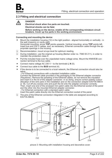
2.3 Fitting and electrical connection<br />
DANGER!<br />
Electrical shock when live parts are touched.<br />
Electrical shocks can be fatal.<br />
Before working on the device, enable all the corresponding miniature circuit<br />
breakers. Cover up live parts in the working environment.<br />
Connecting and mounting the device<br />
o Mount the installation housing (12) in the right position - aligned horizontally or vertically - in<br />
the wall (masonry or cavity wall).<br />
Horizontal mounting: arrow TOP points upwards. Vertical mounting: arrow TOP points left.<br />
Insert bus and 230 V cables, and, as necessary, Ethernet connection cable through the appropriate<br />
openings in the housing.<br />
i Recommendation: mount at eye level for optimum reading.<br />
i During installation, use the original up housing (<strong>Berker</strong> order no. 7590 00 211), in order to<br />
maintain the protection class II.<br />
o Pull the included hose over the unjacketed mains voltage wires. Mount the KNW/EIB connection<br />
terminal to the bus cable.<br />
o Connect mains voltage AC 230 V ~ to the terminals L N (5).<br />
o Connect bus cable to the BUS terminal (4).<br />
o If the device is to be connected to a local network, the Ethernet connection should also be<br />
setup.<br />
- For Ethernet connections with a standard installation cable:<br />
Connect the Ethernet cable provided in the packaging to the Ethernet adapter connector<br />
('Keystone'). Remove the jacketing of the Ethernet cables, do not remove the insulation<br />
and insert it in the lid of the adapter connector. In so doing, ensure correct polarity (colour<br />
allocation of the wire pairs in the installation and on the connection adapter EIA/TIA-568-A<br />
or -B). Cut off any excess wire and push the lid onto the adapter connector correctly.<br />
Then, insert one end of the enclosed mini patch cable into the Ethernet socket of the panel<br />
and the other into the mounted Ethernet adapter connector.<br />
- For Ethernet connection with a standard patch cable:<br />
Insert the patch cable directly into the Ethernet connection socket of the panel.<br />
i The pins of the Ethernet connection integrated in the table are assigned according to<br />
EIA/TIA-568-B.<br />
Order-No. 7574 00 1X<br />
Fitting, electrical connection and operation<br />
picture 3: Mounting with installation housing and decorative cover<br />
Page 8 of 222