Chlorine Monitoring and Dechlorination Techniques Handbook
Chlorine Monitoring and Dechlorination Techniques Handbook
Chlorine Monitoring and Dechlorination Techniques Handbook

Create successful ePaper yourself
Turn your PDF publications into a flip-book with our unique Google optimized e-Paper software.
FINAL REPORT<br />
<strong>Chlorine</strong> <strong>Monitoring</strong> <strong>and</strong> <strong>Dechlorination</strong> <strong>Techniques</strong> H<strong>and</strong>book<br />
Prepared For:<br />
Greater Vancouver Regional District<br />
Drinking Water Treatment Program<br />
Prepared By:<br />
ENKON Environmental Limited<br />
Suite 525 - 1207 Douglas Street<br />
Victoria, B.C. V8W 2E7<br />
&<br />
Norecol, Dames & Moore, Inc.<br />
Suite 1900 - 650 West Georgia Street<br />
Vancouver, B.C. V6B 4N7<br />
November, 1997
<strong>Chlorine</strong> <strong>Monitoring</strong> <strong>and</strong> Dechlorinating <strong>Techniques</strong> H<strong>and</strong>book<br />
TABLE OF CONTENTS<br />
1.0 INTRODUCTION..................................................................................................................... 1<br />
1.1 Background ............................................................................................................. 1<br />
1.2 Chemical Reactions ................................................................................................ 2<br />
1.3 Dechlorinating Agents ............................................................................................ 3<br />
1.4 Other Considerations .............................................................................................. 3<br />
1.5 When to Dechlorinate ............................................................................................. 4<br />
2.0 CHLORINE MONITORING.................................................................................................... 6<br />
2.1 Background ............................................................................................................. 6<br />
2.2 Chemical Analysis .................................................................................................. 6<br />
2.2.1 Orthotolidine Indicator................................................................................ 6<br />
2.2.2 DPD Indicator ............................................................................................. 7<br />
2.2.3 Spectrophotometers..................................................................................... 8<br />
2.2.4 Laboratory Analysis .................................................................................... 8<br />
2.3 Interferences............................................................................................................ 9<br />
2.4 Training................................................................................................................... 9<br />
3.0 APPROACH TO DECHLORINATION................................................................................. 10<br />
3.1 Types of Responses............................................................................................... 10<br />
3.2 General Steps ........................................................................................................ 11<br />
3.2.1 Step 1 - Preparation................................................................................... 11<br />
3.2.2 Step 2 - Notify Authorities <strong>and</strong> Record Activities.................................... 14<br />
3.2.3 Step 3 - Measure the Total Residual <strong>Chlorine</strong> (TRC)............................... 16<br />
3.2.4 Step 4 - Prepare Stock Solution (for Planned Response).......................... 16<br />
3.2.5 Step 5 - Calculate Flow (Q) of Discharge Water ...................................... 17<br />
3.2.6 Step 6 - Determine the Dechlorinating Solution Dosing Rate (for Planned<br />
Response).................................................................................................. 18<br />
3.2.7 Step 7 - Add the Dechlorinating Agent..................................................... 24<br />
3.2.8 Step 8 - Flow Control Measures ............................................................... 25<br />
3.2.9 Step 9 - Monitor the Total Residual <strong>Chlorine</strong> Concentration after<br />
Treatment .................................................................................................. 25<br />
3.2.10 Summary of <strong>Dechlorination</strong> Steps ............................................................ 25<br />
4.0 FLOW CONTROL MEASURES ........................................................................................... 28<br />
4.1 Berms .................................................................................................................... 28<br />
4.2 Swale..................................................................................................................... 29<br />
4.3 Ditches .................................................................................................................. 29<br />
4.4 Holding Tanks....................................................................................................... 29<br />
4.5 Redirection Pipe.................................................................................................... 31<br />
4.6 Constructed Ponds ................................................................................................ 32
<strong>Chlorine</strong> <strong>Monitoring</strong> <strong>and</strong> Dechlorinating <strong>Techniques</strong> H<strong>and</strong>book<br />
5.0 PERMANENT SYSTEMS..................................................................................................... 33<br />
5.1 Ponds..................................................................................................................... 33<br />
5.2 In-line Injection..................................................................................................... 36<br />
5.3 Automated Dosing System.................................................................................... 37<br />
6.0 CASE SCENARIOS ............................................................................................................... 39<br />
6.1 Scenario 1 - Planned, Intermittent Flow Situation................................................ 39<br />
6.1.1 Steps.......................................................................................................... 40<br />
6.2 Scenario 2 - Permanent System ............................................................................ 41<br />
6.2.1 Steps.......................................................................................................... 41
LIST OF FIGURES<br />
Figure 3-1 Approach to <strong>Dechlorination</strong> (Flow Chart)<br />
Figure 3-2 Example of <strong>Dechlorination</strong> Approach<br />
Figure 4-1 Typical Berm Structure<br />
Figure 5-1 Plan View Example of Holding Pond<br />
<strong>Chlorine</strong> <strong>Monitoring</strong> <strong>and</strong> Dechlorinating <strong>Techniques</strong> H<strong>and</strong>book<br />
LIST OF TABLES<br />
Table 3-1 Emergency Response Kit Supplies<br />
Table 3-2 Planned Response Kit Supplies<br />
Table 3-3 Stock Solution Preparation Information<br />
Table 3-4 Pounds of Chemicals Required to Neutralize Residual <strong>Chlorine</strong><br />
Table 3-5 Volume of Sodium Thiosulphate Pentahydrate Required to Neutralize 10,000 L<br />
Table 3-6 Volume of Sodium Thiosulphate Pentahydrate Required to Neutralize 10, 000 gallons<br />
Table 3-7 Weight of Anhydrous Sodium Thiosulphate Required to Neutralize Various<br />
Concentrations of Residual <strong>Chlorine</strong><br />
Table 3-8 Summary of <strong>Dechlorination</strong> Steps<br />
Table 5-1 Examples of Holding Pond Dimensions<br />
APPENDICES<br />
Appendix A <strong>Chlorine</strong> <strong>Monitoring</strong> Kit Suppliers<br />
Appendix B Record of Activities Sheet<br />
Appendix C Dechlorinating Agents<br />
Appendix D Chemical Metering Pump Suppliers<br />
Page iv
<strong>Chlorine</strong> <strong>Monitoring</strong> <strong>and</strong> Dechlorinating <strong>Techniques</strong> H<strong>and</strong>book<br />
INTRODUCTION<br />
This h<strong>and</strong>book is published in combination with a series of Guidelines, which provide<br />
management measures for releases of chlorinated municipal water. Guidelines are available<br />
for the following categories of water use:<br />
Agricultural Water Use<br />
Construction Water Use<br />
Domestic Water Use<br />
Municipal Water Use<br />
Industrial/Commercial Water Use<br />
Based on public input, in June, 1994, the GVRD Board selected the use of chlorine solution<br />
for secondary disinfection of drinking water. Ozone cannot be used because it breaks down<br />
too quickly. The public said they preferred the use of chlorine over chloramine because it<br />
presents a lower risk to the environment - even though chlorine will cost more <strong>and</strong> may add<br />
a chlorine taste <strong>and</strong> odour to the water.<br />
In choosing chlorine over chloramine, the GVRD has already provided its water users with<br />
a first step in mitigating the impacts of potable water discharges by selecting a secondary<br />
disinfectant with a lower potential impact.<br />
1.1 Background<br />
<strong>Chlorine</strong> is a strong oxidizing agent <strong>and</strong> is the oldest method of continuous disinfection for<br />
public water supplies in North America. In the GVRD, chlorine is used as the primary<br />
disinfectant for water supplied to the 18 member municipalities.<br />
<strong>Chlorine</strong>, being a very reactive element, will oxidize organic <strong>and</strong> inorganic matter present<br />
in the water supply <strong>and</strong> in the pipe distribution systems. The chlorine will, therefore,<br />
decrease in concentration with distance from the source to the point where the chlorine level<br />
can become ineffective as a disinfectant. Bacteria growth will occur in distribution systems<br />
when very low levels of chlorine are encountered. Bacterial growth is particularly evident at<br />
the extremities of the pipe distribution systems in the greater Vancouver region. Source<br />
control of bacteria regrowth can be augmented by the use of Best Management Practices such<br />
as flushing/pigging the distribution mains on a routine basis.<br />
In order to address the problem of bacteria growth, the GVRD plans to boost chlorine levels<br />
in the municipal water distribution system using a series of secondary disinfection stations.<br />
These stations will be located throughout the greater Vancouver region.<br />
Page 1
<strong>Chlorine</strong> <strong>Monitoring</strong> <strong>and</strong> Dechlorinating <strong>Techniques</strong> H<strong>and</strong>book<br />
Since the municipal water system is used for more than supplying water for human<br />
consumption, for instance cooling water, the potential exists for this water to be discharged<br />
directly to the environment. If chlorinated water reaches an aquatic system, it has the<br />
potential to kill fish <strong>and</strong> other aquatic organisms because of the chlorine concentration. One<br />
mode of action is likely through damaging the gills, thus preventing the fish from breathing.<br />
Therefore, in many instances, it will be necessary to dechlorinate the water in order to make<br />
it safe for discharge to the environment. This h<strong>and</strong>book provides guidance <strong>and</strong> recommended<br />
dechlorination techniques as well as methods for monitoring chlorine levels in municipal<br />
water.<br />
1.2 Chemical Reactions<br />
<strong>Chlorine</strong> gas hydrolyzes in water almost completely to form hypochlorous acid, under the<br />
following reaction:<br />
Cl2 + 2H2O HOCl + H + + Cl -<br />
The hydrogen ions released in the reaction cause a reduction in pH. The pH is important in<br />
determining to what extent the hypochlorous acid (HOCl) can dissociate to produce<br />
hypochlorite (OCl - ) ions:<br />
HOCl<br />
H + + OCl -<br />
The hypochlorous acid form of chlorine is the prime disinfecting agent. The term free<br />
available chlorine or free chlorine refers to both the HOCL <strong>and</strong> OCl - portions present in<br />
the water. The ratio between HOCL <strong>and</strong> OCl - is primarily a function of pH. For example, 96<br />
percent of the free available chlorine is present as HOCl at pH 6, 75 percent at pH 7 <strong>and</strong> only<br />
3 percent at pH 9.<br />
If chlorine is added to water which contains ammonia, the ammonia will combine with the<br />
chlorine to form chloramines. The portion of chlorine that is present as chloramines as well<br />
as chlorine combined with other specific nitrogenous compounds 1 is referred to as combined<br />
available chlorine . Total residual chlorine (or residual chlorine as used in this h<strong>and</strong>book)<br />
is the sum of the free available chlorine plus the combined available chlorine . This<br />
includes all the forms of chlorine which are able to act as an oxidant <strong>and</strong> are hazardous to<br />
aquatic life.<br />
1 for example, N-chloramides<br />
Page 2
<strong>Chlorine</strong> <strong>Monitoring</strong> <strong>and</strong> Dechlorinating <strong>Techniques</strong> H<strong>and</strong>book<br />
Generally, only free residual chlorine should be present in a municipal water supply, while<br />
both free residual chlorine <strong>and</strong> total residual chlorine can be present in a receiving<br />
environment. Both these forms of chlorine will need to be measured in the field.<br />
1.3 Dechlorinating Agents<br />
To neutralize an oxidant, such as hypochlorous acid, a neutralizing or dechlorinating<br />
chemical can be used. Four types of dechlorinating agents have been used:<br />
sulfur dioxide (SO2)<br />
sodium bisulfite (NaHSO3)<br />
sodium sulfite (Na2SO3)<br />
sodium thiosulfate (Na2S2O3)<br />
Sulfur dioxide is a gas, <strong>and</strong> as such is not routinely used, or recommended because of its<br />
hazardous nature, for field dechlorination purposes. Sodium bisulfite, sodium sulfite, <strong>and</strong><br />
sodium thiosulfate have been used in field application <strong>and</strong> are typically purchased in<br />
powdered or solid forms. Sodium sulfite is available in pucks which are typically 140 gram<br />
solid puck shaped pieces.<br />
Sodium thiosulfate is the most frequently used dechlorinating agent in the greater Vancouver<br />
region. This is due to the fact that sodium sulfite can cause an oxygen depleting environment.<br />
The toxic threshold of sodium sulfite as listed in the MSDS (Material Safety Data Sheet) is<br />
2,600 mg/L as opposed to 24,000 mg/L for sodium thiosulphate. Sodium thiosulplhate is<br />
available in both anhydrous (Na2S2O3) <strong>and</strong> pentahydrate (Na 2S 2O 3 5H 20) forms. The<br />
difference between the two forms is that anhydrous sodium thiosulphate will dissolve much<br />
slower, <strong>and</strong> last a longer time when added to water, such as a creek. On the other h<strong>and</strong>, the<br />
pentahydrate form is already hydrated, <strong>and</strong> therefore will dissolve much faster than the<br />
anhydrous form. It is cheaper to use the less soluble anhydrous form.<br />
It takes about 1.5 parts of sodium thiosulfate pentahydrate (Na2S2O3 . 5 H2O) to neutralize 1<br />
part of chlorine residual. For example, if the residual chlorine in tap water was measured at<br />
1 mg/L, it would take 1.5 lbs of sodium thiosulfate pentahydrate to dechlorinate 100,000<br />
Imp. gallons (455,000 L). A more detailed explanation of how to prepare a neutralizing<br />
compound is shown in Section 3.2.6.<br />
1.4 Other Considerations<br />
Oxygen Depletion<br />
Dechlorinating agents containing sulphite, such as sodium sulfite <strong>and</strong> sodium bisulfite, exert<br />
an oxygen dem<strong>and</strong> on the water it is being applied to. If excess chemical is used <strong>and</strong> it enters<br />
Page 3
<strong>Chlorine</strong> <strong>Monitoring</strong> <strong>and</strong> Dechlorinating <strong>Techniques</strong> H<strong>and</strong>book<br />
a creek or lake, an environmental impact can result because of a reduction in the oxygen<br />
content of the water. Care must be taken to ensure that oxygen levels are not significantly<br />
altered with the addition of such chemicals. The best way to ensure that oxygen is not<br />
depleted is to use sodium thiosulphate as the dechlorinating agent rather than sodium sulphite<br />
or sodium bisulfite.<br />
pH Levels<br />
Although not specifically related to dechlorination it should be noted that chlorine solutions<br />
(eg. sodium hypochlorite) used to super chlorinate water mains have a very high pH level to<br />
ensure that chlorine gas does not form in the solution. Adding sodium hypochlorite to water<br />
having a low buffering capacity, such as is the case with the GVRD water supply, could<br />
cause elevated pH levels. In addition to dechlorinating this disinfection water prior to<br />
discharge, the pH level should be determined prior to discharge of this water <strong>and</strong>, if<br />
necessary, measures taken to adjust the pH to appropriate levels. The optimum pH range is<br />
6.5 to 9.0 as per the BC Environment Approved <strong>and</strong> Working Water Quality Criteria (1996).<br />
If the pH requires adjusting, it can be adjusted using a tank of carbon dioxide bubbled into<br />
the water to reduce a high (basic) pH or by adding sodium bicarbonate to a low (acidic) pH.<br />
1.5 When to Dechlorinate<br />
In order to assess whether dechlorination is necessary during or after a water release, the<br />
following conditions should be considered:<br />
(1) the volume of chlorinated water being discharged;<br />
(2) the concentration of total residual chlorine in the water;<br />
(3) the proximity of the point of discharge to a natural aquatic system; <strong>and</strong><br />
(4) the volume or flow of the receiving environment available to dilute the<br />
release.<br />
For instance, using a garden hose to wash down a truck would not generate sufficient water<br />
to warrant dechlorination. However, creeks should be protected from detergent or silt<br />
releases. Similarly, if there are no natural aquatic systems within several kilometres of the<br />
point of discharge, <strong>and</strong> the volume of water released is low, then the need for dechlorination<br />
techniques would be diminished. In other cases, though, dechlorination would be m<strong>and</strong>atory.<br />
For example, flushing an 8" water main can generate 780 gallons of water per minute <strong>and</strong><br />
higher. This flow exceeds the flow of many small creeks <strong>and</strong> could cause significant impact<br />
if water is discharged directly to a creek without removal of chlorine residuals.<br />
<strong>Dechlorination</strong> is required when the combination of the volume of municipal water being<br />
released, the concentration of total residual chlorine, <strong>and</strong> the proximity of the site to a natural<br />
aquatic system indicates a potential risk to the environment. The type of water releases that<br />
Page 4
<strong>Chlorine</strong> <strong>Monitoring</strong> <strong>and</strong> Dechlorinating <strong>Techniques</strong> H<strong>and</strong>book<br />
require dechlorination can be found in the Guidelines for mitigating the releases of municipal<br />
water from specific types of activities. If there is any doubt as to the need to dechlorinate it<br />
would be more prudent to dechlorinate.<br />
If there is any question about the potential to impact the environment, the chlorine levels<br />
should be monitored at the point of discharge, <strong>and</strong> in the receiving environment.<br />
Page 5
2.1 Background<br />
<strong>Chlorine</strong> <strong>Monitoring</strong> <strong>and</strong> Dechlorinating <strong>Techniques</strong> H<strong>and</strong>book<br />
CHLORINE MONITORING<br />
<strong>Monitoring</strong> for free residual chlorine <strong>and</strong> total residual chlorine (ie. free available plus<br />
combined available chlorine) is a requirement during most dechlorination efforts. The<br />
concentration of residual chlorine in the discharge water will determine if dechlorination<br />
techniques are required, <strong>and</strong> the dosing rate of the dechlorinating agent. The following<br />
sections outline the procedures for monitoring the residual chlorine levels in municipal<br />
water.<br />
2.2 Chemical Analysis<br />
<strong>Chlorine</strong> concentrations can be measured either in the field using simple field kits or in the<br />
laboratory using more sophisticated procedures <strong>and</strong> equipment. Most field kits work from<br />
a similar principal where a chemical (ie. an indicator) is added to a water sample <strong>and</strong> the<br />
colour of the solution is compared to a set of coloured st<strong>and</strong>ards. The colours in the st<strong>and</strong>ards<br />
have been calibrated in a laboratory to match set concentrations of chlorine. For instance, if<br />
a water sample is placed in a glass vial containing an indicator, <strong>and</strong> the solution turns dark<br />
red, this indicates a higher concentration than if the solution turns faint pink.<br />
The limitation to field kits is their detection limits. The detection limit is typically 0.1 ppm,<br />
which is well above environmentally safe levels. The free chlorine concentrations which<br />
have killed fish vary from 0.03 mg/L to 0.05 mg/L depending on exposure time <strong>and</strong> fish<br />
species. However, even though it cannot be quantified, these kits can identify trace<br />
concentrations of chlorine if a faint colour is present. <strong>Dechlorination</strong> should be undertaken<br />
with any sign of colour. Laboratory methods, on the other h<strong>and</strong>, have lower detection limits,<br />
but are generally not applicable because the chlorine dissipates more quickly <strong>and</strong> will be lost<br />
during transport (unless it s in the combined chlorine form).<br />
Examples of the types of field kits available <strong>and</strong> laboratory procedures are given in the<br />
following sections. The field kits can be purchased from local scientific equipment suppliers.<br />
The suppliers will provide current pricing <strong>and</strong> availability of product. The larger suppliers<br />
have websites on the Internet where information on the field kits can be obtained (see<br />
Appendix A for names, addresses, <strong>and</strong> website addresses).<br />
2.2.1 Orthotolidine Indicator<br />
One sampling kit uses a liquid indicator called orthotolidine. The kit includes sampling<br />
vials of preset volumes. The sampler places the water to be tested into the sampling vial <strong>and</strong><br />
Page 6
<strong>Chlorine</strong> <strong>Monitoring</strong> <strong>and</strong> Dechlorinating <strong>Techniques</strong> H<strong>and</strong>book<br />
then pipettes the indicator into the vial. Usually a set number of drops of the indicator are<br />
required. The water in the vial will turn colour following addition of the indicator. By<br />
comparing the colour of the water in the vial to that on a sheet of paper supplied with the kit,<br />
or to a colour disk, the concentration of chlorine is measured. The colours correspond to<br />
concentrations of chlorine in parts per million (ppm or mg/L).<br />
This type of kit usually detects 0.1 to 1.0 ppm chlorine with an accuracy of 0.1 ppm. Cost 2<br />
of the kit is around $130 but varies between suppliers. This kit has not been used recently by<br />
the GVWD staff because of the concern with the chemicals used in the kit. This method is<br />
not recommended since it gives poor accuracy <strong>and</strong> precision <strong>and</strong> a high overall error in<br />
comparison with the other chlorine method 3 .<br />
2.2.2 DPD Indicator<br />
One kit uses N,N-Diethyl-p-Phenylenediamine (DPD) as the indicator solution. This method<br />
determines chlorine content according to the N,N-Diethyl-p-Phenylenediamine (DPD)<br />
method 409F described in the 17th edition of St<strong>and</strong>ard Methods for Examination of Water<br />
<strong>and</strong> Wastewater.<br />
The water is collected in a sample tube <strong>and</strong> the indicator is added to this tube. It uses tablets<br />
or powder to dye water samples to a degree proportional to the chlorine content in the<br />
sample. When the water in the tube changes colour, the colour is compared to 9 or 10 colours<br />
present in similar smaller tubes located on a colour disk. The colour disk is rotated until the<br />
colour closely matches that inside the test tube. The disk colour relates to a concentration.<br />
The method can differentiate between combined chlorine <strong>and</strong> free available forms by<br />
using different types of indicator. Fresh indicator should always be used as old DPD can give<br />
false readings.<br />
This type of kit detects from 0.1 to 5.0 ppm chlorine. Cost of the tablets is around $10 for a<br />
package of ten tablets. Vials are around $20 each. Colour disks cost in the range of $50 to<br />
$250, depending on the supplier <strong>and</strong> the sophistication of the colour disk.<br />
The GVWD 4 staff use the HACH Colour Comparator model CN-D70, which uses the DPD<br />
indicator, for chlorine monitoring. This kit is reliable at low chlorine levels.<br />
2 Costs are estimated based on 1996 dollars. Contact suppliers directly for more accurate costs.<br />
3<br />
4<br />
Harp, Daniel L. Current Technology of <strong>Chlorine</strong> Analysis for Water <strong>and</strong> Wastewater , Technical<br />
Information Series - Booklet No. 17, Hack Technical Center for Applied Analytical Chemistry.<br />
Greater Vancouver Water District<br />
Page 7
<strong>Chlorine</strong> <strong>Monitoring</strong> <strong>and</strong> Dechlorinating <strong>Techniques</strong> H<strong>and</strong>book<br />
Be sure that the reagent expiry date is clearly marked <strong>and</strong> that staff check the expiry date<br />
before using each reagent pouch.<br />
2.2.3 Spectrophotometers<br />
There are a number of field spectrophotometers that can be used for measurement of residual<br />
chlorine levels. One model is a pocket-sized instrument that tests for free <strong>and</strong> total residual<br />
chlorine over the operating range of 0 to 3.9 ppm. The meter reads in 0.01 ppm increments<br />
with an accuracy of 0.05 ppm. The meter itself has dimensions of 4.5 x 12 x 8.9 cm. The<br />
reagent used in these types of instruments is typically DPD, as described above.<br />
The cost of the pocket device is approximately $300. The GVWD staff have had some<br />
difficulties with using this equipment in the field due to weather conditions <strong>and</strong> prefer the<br />
colour comparator kit which can be kept in the service truck.<br />
2.2.4 Laboratory Analysis<br />
Laboratory analysis for total residual chlorine in water is not recommended due to the very<br />
short storage time that a sample can remain stable, <strong>and</strong> the relatively long turnaround time<br />
for results. <strong>Chlorine</strong> dissipates from a water sample very quickly as a result of exposure to<br />
light, increased temperature, <strong>and</strong> agitation. According to the US EPA st<strong>and</strong>ard laboratory<br />
techniques for residual chlorine analysis Method 4500-Cl, samples to be analysed for<br />
residual chlorine should not be stored at all, but analysed immediately.<br />
The US EPA St<strong>and</strong>ard Method 4500-Cl outlines different methods to detect residual<br />
chlorine, including:<br />
the Iodometric Method;<br />
the Amperometric Titration Method;<br />
the Low-Level Amperometric Titration Method<br />
the DPD Colorimetric Method;<br />
the Syringaldazine (FACTS) Method; <strong>and</strong><br />
the Iodometric Electrode Technique.<br />
The advantage of these methods is that the detection limits are as low as 0.010 mg/L (ppm<br />
or 10 g/L (ppb), depending on the sophistication of the equipment.<br />
It is recommended that sampling for total residual chlorine be<br />
completed in the field using a field testing kit to obtain the<br />
best results. In special cases, lower detection limit methods<br />
could be used by setting titration equipment in the field.<br />
Page 8
2.3 Interferences<br />
<strong>Chlorine</strong> <strong>Monitoring</strong> <strong>and</strong> Dechlorinating <strong>Techniques</strong> H<strong>and</strong>book<br />
The field methods used to measure total residual chlorine can give false readings in some<br />
circumstances. For example, the DPD indicator method is subject to interference by oxidized<br />
forms of manganese. The test may indicate chlorine is present when it is the interfering<br />
compound reacting with the indicator to give a false reading. High sample colour <strong>and</strong><br />
turbidity may also cause interference <strong>and</strong> give inaccurate readings.<br />
When an interference is suspected, chlorine free samples should be measured to establish<br />
background readings. This can be done by taking a water sample <strong>and</strong> agitating the water for<br />
a few minutes to decrease chlorine levels in the sample, <strong>and</strong> then taking a chlorine reading<br />
on that sample. If the reading does not decrease repeat the agitation procedure a few more<br />
times. If a positive result is still obtained, it is likely that an interference is present, which<br />
must be taken into account during the monitoring program. For example, in the case of the<br />
pocket photometer the background reading can be subtracted from the reading obtained with<br />
the true sample for low turbidity samples, but not for samples that have a false positive<br />
interference. If there is any doubt in the readings, continue to dechlorinate as a precautionary<br />
measure.<br />
Another interference may occur when the chlorine residual is a high enough concentration<br />
that the reagent (DPD) will bleach out <strong>and</strong> no colour will develop. This will result in a false<br />
negative reading.<br />
2.4 Training<br />
It is necessary to undergo training in procedures for chlorine monitoring as well as general<br />
dechlorination methods prior the use of these methods in the field. Explanation of the<br />
potential problems that can arise by someone knowledgeable in these procedures will reduce<br />
the potential for errors <strong>and</strong> frustrations associated with new procedures. The GVRD, for<br />
example, has developed a training program for staff that will be involved in dechlorination<br />
procedures.<br />
Page 9
3.1 Types of Responses<br />
<strong>Chlorine</strong> <strong>Monitoring</strong> <strong>and</strong> Dechlorinating <strong>Techniques</strong> H<strong>and</strong>book<br />
APPROACH TO DECHLORINATION<br />
The methods <strong>and</strong> equipment used to dechlorinate a water release will be dependent on the<br />
type of water release encountered. For ease of discussion, three types of water releases have<br />
been defined, as follows:<br />
Emergency<br />
Planned Short-term<br />
Permanent<br />
During an emergency water release, such as a water main break, the location <strong>and</strong> volume of<br />
the water release are not known prior to its occurrence. Therefore, equipment, chemicals <strong>and</strong><br />
supplies needed for dechlorination must be assembled prior to the event, <strong>and</strong> they must be<br />
ready to deploy in a very short time. Furthermore, as the conditions of the event are generally<br />
not known until a crew arrives at the site, the dechlorination method used must be relatively<br />
easy <strong>and</strong> quick to deploy in a variety of situations.<br />
As an example, the GVWD has emergency dechlorination kits ready to deploy at all times<br />
<strong>and</strong> are kept in their vehicles. Their response to an emergency water release is to place fibre<br />
mesh bags containing granular sodium thiosulphate in the flow path of the released water<br />
(the bags allow water to easily contact the chemical). These bags <strong>and</strong> ancillary equipment<br />
needed to deploy the bags are made up in advance <strong>and</strong> are immediately available for a<br />
response.<br />
Where the location <strong>and</strong> volume of water to be released are known <strong>and</strong> can be controlled, this<br />
is referred to as a planned release. Planned releases include events such as water main<br />
flushing or concrete curing at a construction site. It should be noted that water originating<br />
from a concrete curing operation likely has a high (basic) pH which can also be lethal to fish.<br />
For a planned release, time is not as critical as an emergency event. Time is available for<br />
preparation at the site. In these situations, the GVWD typically uses a solution of sodium<br />
thiosulphate for dechlorination instead of the solid form. This solution is metered into the<br />
flow of the released water. Using a solution of sodium thiosulphate is much more cost<br />
effective than using bags of solid sodium thiosulphate as much less dechlorinating agent is<br />
used in the dechlorination process.<br />
Where chlorinated water will be released on a long term or permanent basis, such as in<br />
cooling water systems, a more permanent approach to dechlorination is required. In these<br />
Page 10
<strong>Chlorine</strong> <strong>Monitoring</strong> <strong>and</strong> Dechlorinating <strong>Techniques</strong> H<strong>and</strong>book<br />
circumstances, a more engineered approach is used, which is discussed in more detail in<br />
Section 5.0.<br />
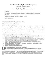
Figure 3-1 outlines a decision flow chart for dechlorination of municipal water releases.<br />
3.2 General Steps<br />
This section discusses the steps for emergency <strong>and</strong> planned response to a chlorinated water<br />
release, where Section 5.0 focuses on the dechlorination approaches for permanent water<br />
releases.<br />
A checklist of nine general steps has been prepared for dechlorination methods:<br />
Step 1 - Preparation<br />
Step 2 - Notify Authorities <strong>and</strong> Record Activities<br />
Step 3 - Measure the Total Residual <strong>Chlorine</strong> (TRC)<br />
Step 4 - Prepare Stock Solution (Planned Response Only)<br />
Step 5 - Determine Flow Rates<br />
Step 6 - Determine Dosing Rate (Planned Response Only)<br />
Step 7 - Add Dechlorinating Agent<br />
Step 8 - Provide Flow Control Measures<br />
Step 9 - Monitor TRC after Treatment<br />
Details of each of these steps are provided in the following sections.<br />
3.2.1 Step 1 - Preparation<br />
The first step in any response to a water release is to be prepared. Both supplies <strong>and</strong><br />
equipment must be prepared in advance, must be readily available, <strong>and</strong> appropriate staff<br />
training is required.<br />
Page 11
Emergency Response<br />
-use bags of<br />
solid thiosulphate<br />
NO<br />
Figure 3-1 Approach to<br />
Dehlorination<br />
Chlorinated Water<br />
Release<br />
Location <strong>and</strong> volume<br />
known prior to release<br />
Is flow short<br />
term?<br />
Flow Control<br />
Required<br />
Berms<br />
Holding Tanks<br />
Swales<br />
Ditches<br />
YES<br />
YES<br />
Planned Response<br />
- use solution of<br />
thiosulphate<br />
YES<br />
NO<br />
Permanent Response<br />
NO<br />
- use solution of<br />
thiosulphate<br />
Discharge to<br />
Environment provided<br />
residual chlorine is<br />
non-detectable
Emergency Response<br />
<strong>Chlorine</strong> <strong>Monitoring</strong> <strong>and</strong> Dechlorinating <strong>Techniques</strong> H<strong>and</strong>book<br />
An emergency response kit should be prepared prior to it being needed. A list of equipment<br />
<strong>and</strong> supplies used by the GVWD for emergency response is shown in Table 3-1. This kit is<br />
always available to the response crew. Photos 1 <strong>and</strong> 2 display a typical emergency kit.<br />
Table 3-1<br />
Emergency Response Kit Supplies<br />
Items<br />
Chemical Supplies - two 20 lb. bags of technical grade anhydrous<br />
sodium thiosulphate<br />
- three or four pre-filled mesh bags filled with<br />
technical grade anhydrous sodium thiosulphate<br />
- 6 spare empty bags<br />
General Equipment - ropes (at least two, 10 m long each)<br />
- record book<br />
- camera, film <strong>and</strong> batteries<br />
- joint sleeves <strong>and</strong> fabricated fittings to adapt to fire<br />
hydrants <strong>and</strong> other facilities<br />
Testing Equipment - field chlorine testing kit (eg: HACH kit)<br />
- Record of Activities Sheet (RAS)/record book<br />
- portable pH meter<br />
Personal Safety<br />
Equipment<br />
- clear plastic goggles (the kind that suction<br />
around your eyes)<br />
- rubber gloves<br />
- particle mask<br />
- MSDS for sodium thiosulphate <strong>and</strong> for the<br />
chlorine testing reagent<br />
Telephone Numbers - a list of municipal, district <strong>and</strong> environmental<br />
agency emergency telephone numbers<br />
Page 13
<strong>Chlorine</strong> <strong>Monitoring</strong> <strong>and</strong> Dechlorinating <strong>Techniques</strong> H<strong>and</strong>book<br />
The approach used by GVWD staff for dechlorination in an emergency situation is to use the<br />
solid form of anhydrous sodium thiosulphate. This agent is put into fibre mesh bags, which<br />
are then placed in the flow path of the released water. Therefore, a number of bags should<br />
be readily available. Rope is included in the equipment list as often the bags need to be tied<br />
in place. Personal safety equipment is also required.<br />
It is important to have Material Safety Data Sheets (MSDS) on the site for both the<br />
dechlorinating agent <strong>and</strong> for the chlorine testing kit. If there is contact with either of these<br />
agents, the MSDS provides information pertaining to treatment, if required. The MSDS will<br />
also indicate the exact personal protection equipment (PPE) that should be worn by workers<br />
who are in contact with the chemicals.<br />
Planned Situation<br />
In a planned release, the equipment <strong>and</strong> supplies will be different from an emergency<br />
response as the liquid form of the dechlorinating agent can be used.<br />
Sufficient dechlorinating agent should be delivered to the site prior to the beginning of any<br />
planned operation. Excess dechlorinating agent should be available at all times. Since it may<br />
not be available from the suppliers on short notice.<br />
Table 3-2 indicates typical supplies that should be kept on site for a planned response.<br />
3.2.2 Step 2 - Notify Authorities <strong>and</strong> Record Activities<br />
In an emergency situation, it is important to notify the correct authorities immediately upon<br />
learning of an unplanned release of chlorinated water. Notify the authorities with jurisdiction<br />
in the vicinity of the release. For instance, if a City of Vancouver water main broke in<br />
Vancouver, the City would have jurisdiction <strong>and</strong> has a designated reporting number for water<br />
main breaks. Alternatively, if a water main operated by the GVWD broke, the GVWD should<br />
be contacted. Exact procedures for contacting authorities should be pre-planned by all<br />
municipalities, <strong>and</strong> the GVWD. An Emergency Call Report Form, as outlined in the Generic<br />
Environmental Emergency Response Plan for Chlorinated Water (GVRD 1997), should be<br />
filled out to record all persons <strong>and</strong> agencies notified.<br />
In the event of a large spill, the Provincial Emergency Program (PEP) should be contacted.<br />
Although, they will likely refer the call to the Department of Fisheries <strong>and</strong> Oceans, this<br />
agency should also be contacted directly.<br />
Page 14
<strong>Chlorine</strong> <strong>Monitoring</strong> <strong>and</strong> Dechlorinating <strong>Techniques</strong> H<strong>and</strong>book<br />
Table 3-2<br />
Planned Response Kit<br />
Items<br />
Chemical Supplies - excess dechlorinating agent to prepare the stock<br />
solution of liquid dechlorinating agent<br />
General Equipment - 1 record book<br />
- barrels or holding tank(s) for dechlorinating solution<br />
- electric generator <strong>and</strong> mixer<br />
- joint sleeves <strong>and</strong> fabricated fittings to use with tanks<br />
<strong>and</strong> mixer<br />
- balance to measure mass of dechlorinating agent that<br />
will be required to mix the stock solution<br />
- chemical metering pump with a quick-fix-it kit<br />
containing spare parts in the event that the pump<br />
becomes disabled<br />
- source of water to mix the stock solution<br />
- flow meter<br />
Testing Equipment - field chlorine testing kit (eg: HACH kit)<br />
- flow meter, if required for permanent situation<br />
Personal Safety<br />
Equipment<br />
- clear plastic goggles (the kind that suction around your<br />
eyes)<br />
- rubber gloves<br />
- particle mask<br />
- MSDS for sodium thiosulphate <strong>and</strong> for the chlorine<br />
testing reagent<br />
Telephone Numbers - a list of municipal, district <strong>and</strong> environmental agency<br />
emergency telephone numbers<br />
Page 15
<strong>Chlorine</strong> <strong>Monitoring</strong> <strong>and</strong> Dechlorinating <strong>Techniques</strong> H<strong>and</strong>book<br />
It is recommended that a Record of Activities sheet (RAS) be completed for each<br />
dechlorination event, whether it be an emergency response or a planned situation. The sheet<br />
records such information as the date, the staff involved, the residual chlorine levels, <strong>and</strong><br />
dechlorination techniques. A sample of RAS for both emergency <strong>and</strong> planned situations is<br />
provided in Appendix B.<br />
The RAS will become invaluable both as historical information, <strong>and</strong> as a record of due<br />
diligence. It may also provide important incite into refining different dechlorination<br />
techniques.<br />
3.2.3 Step 3 - Measure the Total Residual <strong>Chlorine</strong> (TRC)<br />
For either an emergency or a planned event, the total residual chlorine (TRC) concentration<br />
should be measured in the water that is being released or planned to be released. A field<br />
testing kit, as discussed in Section 2.0, should be used for this purpose. A number of samples<br />
should be taken to ensure reliability of the numbers.<br />
3.2.4 Step 4 - Prepare Stock Solution (for Planned Response)<br />
The liquid form of sodium thiosulphate is recommended for use in planned events. In this<br />
case, it is more cost effective to prepare your own stock solution of sodium thiosulphate than<br />
purchasing it. A solution of dechlorinating agent can easily be prepared on-site. Stock<br />
solutions are made up by mixing the solid form (usually crystals) of dechlorinating agent,<br />
such as sodium thiosulphate pentahydrate, with water. Two forms of sodium thiosulphate can<br />
be purchased: sodium thiosulphate (Na2S2O3) in the anhydrous form <strong>and</strong> sodium thiosulphate<br />
penthydrate (Na2S2O3 5H20). As the pentahydrate form is the easiest to dissolve <strong>and</strong> is<br />
typically used, this form is used in all of the calculations for this manual.<br />
The strength of a stock solution is measured as a percentage by weight. For instance, a 10%<br />
stock solution of sodium thiosulphate pentahydrate would contain 10% by weight of sodium<br />
thiosulphate pentahydrate <strong>and</strong> 90% by weight of water.<br />
Table 3-3 outlines the mass of sodium thiosulphate pentahydrate required per unit volume<br />
of water to prepare different strengths of stock solution. A list of chemical suppliers is<br />
provided in Appendix C.<br />
Page 16
<strong>Chlorine</strong> <strong>Monitoring</strong> <strong>and</strong> Dechlorinating <strong>Techniques</strong> H<strong>and</strong>book<br />
Table 3-3<br />
Stock Solution Preparation<br />
Required Mass of Sodium Thiosulphate Pentahydrate<br />
per Unit Volume of Water<br />
Strength of<br />
Solution<br />
(% by<br />
weight as<br />
grams of<br />
solute/100 g<br />
water)<br />
Mass (g) of<br />
Sodium<br />
Thiosulphate<br />
Pentahydrate<br />
needed to be<br />
added per<br />
Litre of water<br />
(g/L)<br />
Mass (g) of<br />
Sodium<br />
Thiosulphate<br />
Pentahydrate<br />
per Gallon of<br />
water (g/imp.<br />
gallon)<br />
1% 10.1 46.0<br />
2% 20.3 92.4<br />
5% 52.0 236.6<br />
10% 108.3 492.8<br />
Preparation of a 45 gallon drum of 2% sodium thiosulphate pentahydrate would be as<br />
follows:<br />
1) Using the table above, 0.0924 kg or 92.4 g of sodium thiosulphate pentahydrate must be<br />
added to each gallon of water.<br />
2) For 45 gallons, it would take ( 92.4 g) x (45 gallons) = 4,158 grams or about 4.2 kg.<br />
3.2.5 Step 5 - Calculate Flow (Q) of Discharge Water<br />
Flow rates are required in order to calculate the corresponding dosing rate of dechlorinating<br />
solution required to neutralize the discharge water. Two ways to determine the flow rate (Q)<br />
of discharge water are by calculations or by measurement. A third way would be to estimate<br />
flow by experience, however, this is obviously not as accurate.<br />
Page 17
Calculating Flow Rates<br />
<strong>Chlorine</strong> <strong>Monitoring</strong> <strong>and</strong> Dechlorinating <strong>Techniques</strong> H<strong>and</strong>book<br />
It is possible to calculate the flow rate (Q) of water by knowing the velocity of water being<br />
discharged, <strong>and</strong> the cross-sectional area of the source of discharge, eg., a pipe. The following<br />
steps outline how to calculate the flow rate knowing the velocity of water exiting the pipe:<br />
i) Cross Sectional Area of Pipe (CA) = 1/4 π d 2 ; where π = 3.14... <strong>and</strong><br />
d = diameter in metres<br />
ii) Calculate flow in cubic metres/second (m 3 /s) = (CA) x (Velocity of water in<br />
m/s)<br />
iii) Calculate the flow in L/min (Q) = (m 3 /s) x 1000 L/m 3 x 60 s/min<br />
The value for Q will be in L/min (litres per minute).<br />
Flow Meter<br />
The flow rate at the discharge from the pipe can be measured using a flow or current meter.<br />
Flow meters can be purchased from local suppliers. The concept involves placing a probe or<br />
stick with a bucket wheel on the end into the flow of water. Water velocity is determined by<br />
counting the number of revolutions of the bucket wheel over time. The operator can<br />
manually convert the number of revolutions <strong>and</strong> compare them to a rating chart.<br />
3.2.6 Step 6 - Determine the Dechlorinating Solution Dosing Rate (for Planned Response)<br />
In this section, two approaches are given related to the way the dechlorinating agent is added<br />
to the released water. In the first approach, the volume of the stock solution needed to<br />
dechlorinate a specific flow rate <strong>and</strong> chlorine concentration is used. In the second approach,<br />
the weight of the dechlorinating agent needed to dechlorinate a specific flow rate <strong>and</strong><br />
chlorine concentration is used.<br />
Basis of Calculations<br />
For all calculations, the dechlorinating rates given in the AWWA St<strong>and</strong>ard for Disinfecting<br />
Water Mains (1986) was used as follows:<br />
Page 18
<strong>Chlorine</strong> <strong>Monitoring</strong> <strong>and</strong> Dechlorinating <strong>Techniques</strong> H<strong>and</strong>book<br />
Table 3-4. Pounds of Chemicals Required to<br />
NeutralizeVarious Residual <strong>Chlorine</strong> Concentrations<br />
in 100 000 U.S. gallons (378,500 L) of water.<br />
Residual <strong>Chlorine</strong><br />
Conc. (mg/L)<br />
Sodium<br />
Thiosulfate<br />
Pentahydrate<br />
(Na2S2O3 5H2O)<br />
0.3 0.4 (0.16) 1<br />
0.6 0.7 (0.33)<br />
0.9 1.1(0.49)<br />
1 1.2 (0.544)<br />
1.3 1.6(0.71)<br />
1 () denotes kg<br />
Volumes of Stock Solutions needed for <strong>Dechlorination</strong><br />
Tables 3-5 <strong>and</strong> 3-6 provides the volumes of stock solutions of dechlorinating agent (in mL)<br />
required to dechlorinate 10,000 litres <strong>and</strong> 10,000 Imp. gallons of chlorinated water,<br />
respectively, using a solution of sodium thiosulphate pentahydrate (Na2S2O3 5H20).<br />
Simple ratios can be used to calculate the required volume of stock solution for values of<br />
TRC which are not indicated in the Tables.<br />
Page 19
Trace Residual<br />
<strong>Chlorine</strong> (TRC) as<br />
mg/L present in<br />
the water to be<br />
neutralized<br />
<strong>Chlorine</strong> <strong>Monitoring</strong> <strong>and</strong> Dechlorinating <strong>Techniques</strong> H<strong>and</strong>book<br />
Table 3-5<br />
Volume (in mL) of Sodium Thiosulphate Pentahydrate Solution<br />
Required to Neutralize 10,000 Litres of Chlorinated Water<br />
Stock Solution of Sodium Thiosulphate Pentahydrate<br />
1% 2% 5% 10%<br />
0.1 142 71 28 13<br />
0.3 427 212 83 40<br />
0.5 711 354 138 66<br />
0.7 996 496 193 93<br />
0.9 1281 637 221 119<br />
1 1423 708 276 133<br />
2 2846 1416 553 265<br />
NB: Stock solution can be prepared by using sodium thiosulphate pentahydrate. Refer to Table 3-3 for requirements<br />
to make up the solutions.<br />
Page 20
Trace Residual<br />
<strong>Chlorine</strong> (TRC) as<br />
mg/L present in<br />
the water to be<br />
neutralized<br />
<strong>Chlorine</strong> <strong>Monitoring</strong> <strong>and</strong> Dechlorinating <strong>Techniques</strong> H<strong>and</strong>book<br />
Table 3-6<br />
Volume (in mL) of Sodium Thiosulphate Pentahydrate Solution<br />
Required to Neutralize 10,000 Gallons of Chlorinated Water<br />
Stock Solution of Sodium Thiosulphate Pentahydrate<br />
1% 2% 5% 10%<br />
0.1 647 322 126 60<br />
0.3 1,942 966 377 95<br />
0.5 3,237 1,610 629 302<br />
0.7 4,531 2,255 880 423<br />
0.9 5,826 2,899 1,132 543<br />
1 6,473 3,221 1,257 604<br />
2 12,947 6,441 2,516 1,207<br />
NB: Stock solution can be prepared by using sodium thiosulphate pentahydrate. Refer to Table 3-3 for requirements<br />
to make up the solutions.<br />
Page 21
<strong>Chlorine</strong> <strong>Monitoring</strong> <strong>and</strong> Dechlorinating <strong>Techniques</strong> H<strong>and</strong>book<br />
This information can be used to calculate the volume of dechlorinating agent needed for<br />
different flow rates. For example, if one had a flow rate of 250 gallons per minute (GPM),<br />
this would mean a volume of 15,000 gallons per hour would need to be dechlorinated. If the<br />
TRC in the water was 1 mg/L <strong>and</strong> a 2% stock solution of sodium thiosulphate pentahydrate<br />
was prepared, this would mean that 4,832 mL (Table 3.6*1.5 to convert to 15,000 gallons)<br />
or about 4.8 L would have to be metered into the flow over a one hour period or a stock<br />
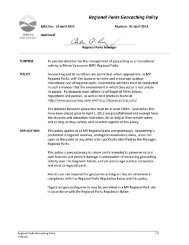
solution flow rate of 80.5 mL per minute. Figure 3-2 illustrates an example of a dechlorination<br />
system.<br />
Weight of Sodium Thiosulphate for Different Flow Rates <strong>and</strong> <strong>Chlorine</strong> Concentrations<br />
Table 3-7 provides the weight of sodium thiosulphate pentahydrate needed to neutralize<br />
various concentrations of chlorine at different flow rates. These values have been taken<br />
directly from the BCWWA School Committee 1994 UBC Operations Workshop 5 report using<br />
the 1.6 multiplier for conversion of anhydrous form to the pentahydrate form.<br />
Table 3-7 Weight of Sodium Thiosulphate Pentahydrate Needed to Neutralize Various<br />
Concentrations of <strong>Chlorine</strong> at Different Flow Rates. Units are pounds of sodium<br />
thiosulphate pentahydrate per hour.<br />
<strong>Chlorine</strong> Concentration in mg/L<br />
Flow<br />
(GPM)<br />
0.5 1 2.5<br />
100 0.048 0.096 0.24<br />
250 0.095 0.19 0.48<br />
500 0.19 0.38 0.96<br />
1000 0.38 0.77 1.92<br />
2000 0.77 1.54 3.84<br />
5 BCWWA School Committee 1994 UBC Operations Workshop. Disinfection of Water Systems <strong>and</strong><br />
<strong>Dechlorination</strong> of Discharges to the Environment. Monday, May 16, 1994.<br />
Page 22
Example of<br />
De-Chlorinating Set-up<br />
November, 1997<br />
GVRD<br />
Figure 3-2<br />
Job# 1000-002 ENKON Environmental Limited
<strong>Chlorine</strong> <strong>Monitoring</strong> <strong>and</strong> Dechlorinating <strong>Techniques</strong> H<strong>and</strong>book<br />
An example is used to illustrate the use of this table. Assume that there is release of 500<br />
GPM of chlorinated water with a residual chlorine concentration of 2.5 mg/L. Using Table<br />
3.7, a flow rate with this chlorine concentration could be neutralized by adding 0.96 pounds<br />
of sodium thiosulphate pentahydrate over each one-hour period. As it is much easier to add<br />
this agent as a solution, 0.96 pounds of sodium thiosulphate pentahydrate is added to 45<br />
gallons of water. The 45 gallons of solution is then metered into the flow over that one hour<br />
period. Alternatively, 1.92 pounds of agent could be added to 45 gallons of water <strong>and</strong> used<br />
over a two hour period.<br />
3.2.7 Step 7 - Add the Dechlorinating Agent<br />
Emergency Response<br />
For an emergency response, mesh bags containing the solid form of anhydrous sodium<br />
thiosulphate should be placed directly into the flow path of the released water. If chlorinated<br />
water has already entered a stream or water body then a bag of dechlorinating agent should<br />
also be placed directly into the water body. These bags may need to be secured by rope to<br />
maintain their position. Although this approach uses excess dechlorinating agent it is the<br />
quickest <strong>and</strong> easiest method to employ. In some cases, it may also be necessary to h<strong>and</strong><br />
broadcast dechlorinating agent into the water, if bags cannot be used effectively.<br />
During emergency response it may be necessary to divert, or temporarily store the water in<br />
order to provide more control for dechlorination. Details of flow control methods are<br />
provided in Section 4.0.<br />
Planned Response<br />
For a planned response, it is more cost effective to use a solution of sodium thiosulphate.<br />
Where <strong>and</strong> how the dechlorinating agent is added will be critical factors in successfully<br />
neutralizing chlorine residuals. The single most important factor is to allow the<br />
dechlorinating agent to thoroughly mix with the water.<br />
The point of chemical addition should be chosen based on mixing capability. A chemical<br />
metering pump provides the best way to both control the injection rate of dechlorinating<br />
agent, <strong>and</strong> ensure that sufficient dechlorinating agent is applied to the discharge water. Some<br />
specifications for chemical metering pumps are provided in Appendix E.<br />
Figure 3-2 illustrates an example of a dechlorination plan that has been used by the GVWD<br />
staff. In this case, a chemical metering pump is attached to piping, which originates at two<br />
storage drums. The pipe is directed toward a mixing unit. An example of a mixing unit is an<br />
energy dissipater, normally used when flushing water mains. It is a rectangular metal box<br />
Page 24
<strong>Chlorine</strong> <strong>Monitoring</strong> <strong>and</strong> Dechlorinating <strong>Techniques</strong> H<strong>and</strong>book<br />
approximately 1 m long <strong>and</strong> 30 cm wide. Water from the water main <strong>and</strong> the dechlorinating<br />
solution are both directed into the mixing unit. From the mixing unit, the flow travels to a<br />
flow control area, such as the pond shown in the Figure 3.2. The pond is used as extra<br />
insurance to ensure sufficient mixing of the dechlorinating agent with the chlorinated water<br />
prior to discharging the treated water to a natural water course. A flow meter is used to<br />
estimate flow.<br />
If a metering pump is not used, it may be possible to set up a gravity flow system, although<br />
this would be less accurate.<br />
3.2.8 Step 8 - Flow Control Measures<br />
In some cases, it may be necessary to employ flow control measures. Flow control measures<br />
serve two purposes, they prevent or delay water from reaching a receiving environment, <strong>and</strong>,<br />
thus, provide more time for mixing of the chlorinated water with the dechlorinating solution.<br />
If it is determined that more time for mixing is required, or that diversions are necessary for<br />
the protection of aquatic life, flow control measures should be employed. Section 4.0<br />
provides detailed descriptions of flow control measures that can be used on-site.<br />
3.2.9 Step 9 - Monitor the Total Residual <strong>Chlorine</strong> Concentration after Treatment<br />
Monitor the discharge water for total residual chlorine (TRC) prior to it reaching the<br />
receiving environment throughout the dechlorination process. Non-detectable readings<br />
should be obtained at all times. Use one of the monitoring procedures outlined in Section 2.0.<br />
3.2.10 Summary of <strong>Dechlorination</strong> Steps<br />
If detectable concentrations of chlorine are found in the<br />
discharge water, the flow of water should be stopped or<br />
redirected to an area to allow additional dechlorination.<br />
Table 3-8 provides a summary of the steps needed for dechlorination.<br />
Page 25
<strong>Chlorine</strong> <strong>Monitoring</strong> <strong>and</strong> Dechlorinating <strong>Techniques</strong> H<strong>and</strong>book<br />
Table 3-8<br />
Summary of Dechlorinating Steps<br />
Steps Emergency Response Planned Response<br />
Step 1 - Preparation - prepare emergency response<br />
kit in advance<br />
Step 2 - Notify Authorities <strong>and</strong><br />
Record Activities<br />
- notify the authorities having<br />
jurisdiction in the area of the<br />
release of chlorinated water<br />
- record all activities in the<br />
field for future reference <strong>and</strong><br />
as part of the due diligence<br />
process<br />
- have excess<br />
dechlorinating agent onsite<br />
- have tools <strong>and</strong><br />
equipment ready,<br />
including spare parts<br />
- record all activities in<br />
the field for future<br />
reference <strong>and</strong> as part of<br />
the due diligence<br />
process<br />
Step 3 - Measure the TRC - assume chlorine is present - measure using field<br />
monitoring kit<br />
Step 4 - Prepare Stock Solution not applicable - prepare the solution in<br />
advance using<br />
information provided in<br />
tables<br />
Step 5 - Determine Flow Rates - estimate flow as best as<br />
possible<br />
- determine flow rate by<br />
calculating, measuring<br />
or estimating<br />
- can also determine total<br />
volume over a set time<br />
period using the flow<br />
rate<br />
Step 6 - Determine Dosing Rate - overdosing is best approach - determine dosing rate of<br />
dechlorinating solution<br />
Step 7 - Add Dechlorinating<br />
Agent<br />
- add solid dechlorinating<br />
agent in pre-filled fibre mesh<br />
bags<br />
- add dechlorinating<br />
agent solution by using<br />
chemical metering<br />
pump<br />
Page 26
<strong>Chlorine</strong> <strong>Monitoring</strong> <strong>and</strong> Dechlorinating <strong>Techniques</strong> H<strong>and</strong>book<br />
Table 3-8<br />
Summary of Dechlorinating Steps<br />
Steps Emergency Response Planned Response<br />
Step 8 – Provide Flow Control<br />
Measures<br />
Step 9 - Monitor TRC after<br />
Treatment<br />
- as required to protect<br />
aquatic life<br />
- as required to provide for<br />
more mixing<br />
- monitor for TRC using field<br />
measuring device in release<br />
water <strong>and</strong> receiving<br />
environment<br />
- as required to protect<br />
aquatic life<br />
- as required to provide<br />
for more mixing<br />
- monitor for TRC using<br />
field monitoring device<br />
in released water <strong>and</strong><br />
in receiving<br />
environment<br />
Page 27
<strong>Chlorine</strong> <strong>Monitoring</strong> <strong>and</strong> Dechlorinating <strong>Techniques</strong> H<strong>and</strong>book<br />
FLOW CONTROL MEASURES<br />
During both emergency <strong>and</strong> planned responses, it may be necessary to construct temporary<br />
or permanent flow control measures. Flow control measures involve construction of physical<br />
structures to provide both the opportunity for better mixing of the dechlorinating agent than<br />
would have been otherwise obtained without these structures, <strong>and</strong> to prevent discharge water<br />
from entering directly into a water body, without treatment.<br />
A number of relatively simple measures can be taken to provide flow control. These<br />
measures may be used separately or, in some cases, a combination of measures may be<br />
appropriate, as follows:<br />
• berms<br />
• swales<br />
• ditches<br />
• holding tanks<br />
• redirection pipes<br />
• ponds<br />
It should be noted that high water flows also cause bank erosion <strong>and</strong> scouring in creeks. For<br />
more guidance on this aspect, refer to the L<strong>and</strong> Development Guidelines (DFO <strong>and</strong> Ministry<br />
of Environment, L<strong>and</strong>s <strong>and</strong> Parks, 1992).<br />
4.1 Berms<br />
Berms can be constructed to control flows or direct water towards ponds or away from a<br />
receiving water body to allow easier addition of the dechlorinating agent <strong>and</strong> appropriate<br />
mixing. There are a number of simple materials that could be used to construct a berm<br />
including:<br />
• s<strong>and</strong> bags<br />
• hay bales<br />
• gravel with a filter fabric core<br />
• plywood<br />
S<strong>and</strong> bags are a good way to construct a temporary berm. S<strong>and</strong> bags placed in a semicircle<br />
can be used to enclose the area of discharge. If the s<strong>and</strong> bags are used in combination with<br />
a depression in the ground, a pond may be formed allowing residence time of the water in<br />
the depression prior to discharge. These bags could be prepared at the site if the appropriate<br />
materials are present, or brought to the site. Hay bales may be used in a similar manner.<br />
Page 28
<strong>Chlorine</strong> <strong>Monitoring</strong> <strong>and</strong> Dechlorinating <strong>Techniques</strong> H<strong>and</strong>book<br />
In some cases, it may be necessary to make an earth berm or small depression, for example,<br />
using a backhoe. This could easily be done at construction sites. An earth berm can use<br />
material present on-site.<br />
4.2 Swale<br />
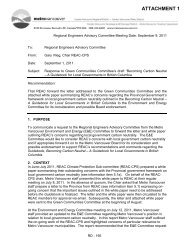
Figure 4-1 illustrates a typical berm structure.<br />
Using a swale or other natural depression could provide an area for the necessary mixing <strong>and</strong><br />
residence time. If the natural setting is such that a low lying field or swale is present near the<br />
site, the discharge water can be redirected into the swale. Constructing a berm at one end of<br />
the swale could increase the holding capacity significantly. Addition of the dechlorinating<br />
agent into the swale will provide good mixing prior to reaching the receiving environment.<br />
A combination of berms <strong>and</strong>/or piping may be required to ensure that the discharge water<br />
travels into the swale first prior to reaching the receiving environment.<br />
4.3 Ditches<br />
A ditch can provide a mixing zone <strong>and</strong> the residence time needed to apply the dechlorinating<br />
agent. Check dams could also be used in the ditch to retain <strong>and</strong> pond the water to improve<br />
mixing. S<strong>and</strong> bags <strong>and</strong> hay bales can be used as check dams, or used to direct the discharge<br />
water into the ditch if it is not already moving in that direction. The ditch used should,<br />
however, have no environmental significance in terms of aquatic habitat. If there is any doubt<br />
as to the significance of the ditch, the DFO should be contacted.<br />
Add the dechlorinating agent solution at the point where the water enters the ditch. This will<br />
allow the dechlorinating agent to mix with the water in the ditch.<br />
4.4 Holding Tanks<br />
In some cases, space may be at a minimum <strong>and</strong> ditches or swales may not be available. In<br />
these situations, holding tanks provide a controlled structure for mixing of the dechlorinating<br />
agent.<br />
Page 29
Job#1000-002<br />
mixingarea<br />
bagsofsodium<br />
thiosulphate<br />
fish<br />
bearing<br />
stream<br />
TypicalBermStructure<br />
GVRD<br />
November,1997<br />
Figure4-1<br />
ENKONEnvironmentalLimited
<strong>Chlorine</strong> <strong>Monitoring</strong> <strong>and</strong> Dechlorinating <strong>Techniques</strong> H<strong>and</strong>book<br />
The size of the holding tank should be such that water entering the holding tank has a<br />
residence time of at least a few minutes. For instance, if the structure discharging water is<br />
flowing at a rate of 50 gallons per minute, the holding tank should be capable of holding at<br />
least 150 gallons or 3 minutes of flow. In the case of larger volumes tanker trucks, which<br />
hold greater than 3,000 gallons, could be used. In these case the truck has its own pumps that<br />
would likely h<strong>and</strong>le the flows. In very low flows, a 45 gallon drum may be sufficient.<br />
The water will likely need to be redirected into the holding tank. A redirection pipe can be<br />
used to accomplish this. For instance, on an 8" water main, use 8" diameter PVC pipe<br />
connected to the discharge end of the water main. Elbows, connectors <strong>and</strong> adaptors can be<br />
used to manipulate the pipe route. Direct the pipe to the bottom half of one end of the<br />
holding tank.<br />
Once the pipe is directing water into the holding tank, the liquid dechlorinating agent can be<br />
added into the holding tank by tapping into the tank.<br />
Water can be emptied out of the tank by constructing a tap on the opposite end of the tank.<br />
The tap will allow for controlled discharge from the tank. The tap should be placed in the op<br />
quarter of the tank. This will allow the water to enter at the bottom, mix with the<br />
rechlorinating agent <strong>and</strong> rise to the top where it empties out, thus providing for optimum<br />
mixing.<br />
4.5 Redirection Pipe<br />
A redirection pipe can be used to redirect the flow of water to a specific area or into a<br />
holding tank. It could also be used as a treatment option if an in-line injection system is used<br />
to inject the dechlorinating agent into the pipe.<br />
The best material for constructing a redirection pipe is PVC (polyvinylchloride) since it<br />
resists corrosion <strong>and</strong> is lightweight for easy manoeuvrability. PVC pipe is reasonably priced,<br />
readily available, <strong>and</strong> can be obtained in various pipe sizes with appropriate adaptors for oddsized<br />
pipe from most hardware stores.<br />
Construct the redirection pipe such that it is connected to the discharge point <strong>and</strong> extends to<br />
the area that will be used for adding the dechlorinating agent. Alternatively, if the<br />
dechlorinating agent is to be added into the redirection pipe itself, there should be an<br />
injection point at the end closest to the source of the chlorinated water. This permits the<br />
dechlorinating agent to mix within the redirection pipe prior to entering the environment.<br />
The injection point can be a vertical pipe which intercepts the discharge pipe. The injection<br />
point can be constructed by putting a T-joint into the pipe. The vertical pipe should not be<br />
Page 31
<strong>Chlorine</strong> <strong>Monitoring</strong> <strong>and</strong> Dechlorinating <strong>Techniques</strong> H<strong>and</strong>book<br />
higher than 1 m so that the dechlorinating agent does not have to be lifted by the operator<br />
during the process. A chemical metering pump can be fitted to the top of the injection point<br />
to allow the operator to control the flow rate of dechlorinating chemicals into the injection<br />
point.<br />
4.6 Constructed Ponds<br />
Large constructed ponds are not likely to be used for short term or emergency response<br />
situations. However, they may be appropriate for long term or permanent discharges. Details<br />
of holding ponds are provided in Section 5.0.<br />
Page 32
<strong>Chlorine</strong> <strong>Monitoring</strong> <strong>and</strong> Dechlorinating <strong>Techniques</strong> H<strong>and</strong>book<br />
PERMANENT SYSTEMS<br />
Permanent systems would apply to water releases such as cooling water distribution systems,<br />
agricultural sites with process or irrigation water, <strong>and</strong> in line syphon systems used to dewater<br />
manholes. A long term solution is needed for dechlorination in these cases <strong>and</strong> the system<br />
should allow mechanical dosing as it would not be practical to have the process completed<br />
manually.<br />
5.1 Ponds<br />
One approach is to discharge the chlorinated water into a pond prior to its release. Two<br />
methods could be used.<br />
Pond Size<br />
• storing the water in a holding pond <strong>and</strong> recirculating it for re-use on-site,<br />
with no discharge (no dechlorination needed); or<br />
• injecting a liquid dechlorinating agent, allowing the water to mix in the<br />
pond, <strong>and</strong> discharging the water to the environment following thorough<br />
mixing.<br />
The size of the holding pond will depend on the flow rate <strong>and</strong> required residence time as well<br />
as the end use of the water in the pond. The general configuration should be rectangular with<br />
the inlet <strong>and</strong> outlet pipes located at opposite ends of the rectangle. This allows a longer time<br />
for mixing of the water. Baffles may also be needed to prevent short circuiting of the water<br />
flow. The pond will need to be sufficient in size to take into account the potential uses.<br />
Pond Dimensions<br />
A pond excavated to a depth not exceeding one metre, <strong>and</strong> measuring 3 m wide by 6 m long<br />
will hold 18, 000 L (4,000 gallons) of water. This should be sufficient to h<strong>and</strong>le the volume<br />
of water from a typical 4" water main given a flow rate of 250 to 300 gallons per minute. The<br />
pond will be filled every 12 to 15 minutes.<br />
As the diameter of the pipe gets larger, <strong>and</strong> the flow rates increase, it will take less time to<br />
fill the same size pond. For instance, an 8" pipe can have a flow rate of 780 gallons/minute,<br />
depending on the pressure in the line. In this case, it would take approximately 3 minutes to<br />
fill the same size pond. This means, that the pond size should be increased to maximize the<br />
water retention time, <strong>and</strong> therefore the mixing time in the pond. The longer the water is<br />
retained in the pond, the better it will be mixed with the dechlorinating agent. Table 5-1<br />
Page 33
<strong>Chlorine</strong> <strong>Monitoring</strong> <strong>and</strong> Dechlorinating <strong>Techniques</strong> H<strong>and</strong>book<br />
provides a guide to increasing the size of the holding pond with the size of the pipe or flow<br />
rate.<br />
The banks of the pond should be vegetated or armoured with rip rap in order to prevent bank<br />
erosion over time. In addition, there should be a 0.5 m high freeboard around the entire pond.<br />
Figure 5-1 illustrates a plan view of a holding pond.<br />
Pipe<br />
Diameter<br />
(inches)<br />
Flow rate<br />
(gallons per<br />
minute or GPM<br />
<strong>and</strong><br />
litres per second<br />
or LPS)<br />
4" 200 GPM<br />
15 LPS<br />
6" 450 GPM<br />
34 LPS<br />
8" 780 GPM<br />
59 LPS<br />
10" 1200 GPM<br />
91 LPS<br />
12" 1750 GPM<br />
133 LPS<br />
14" 2400 GPM<br />
182 LPS<br />
16" 3150 GPM<br />
239 LPS<br />
18" 3975 GPM<br />
301 LPS<br />
Table 5-1<br />
Examples of Pond Dimensions<br />
Volume 1<br />
produced after<br />
10 minutes<br />
(gallons/litres)<br />
2,000 gal.<br />
9,100 L<br />
4,500 gal.<br />
20,475 L<br />
7,800 gal.<br />
35,490 L<br />
12,000 gal.<br />
54,600 L<br />
17,500 gal.<br />
79,625 L<br />
24,000 gal.<br />
109,200 L<br />
31,500 gal.<br />
143,325 L<br />
39,750 gal.<br />
180,863 L<br />
Minimum required pond<br />
dimensions<br />
(Depth x width x length in feet <strong>and</strong><br />
metres)<br />
3 x 10 x 10 feet<br />
1 x 3 x 3 metres<br />
1 x 3 x 7<br />
1 x 4 x 9<br />
1 x 5 x 11<br />
1 x 5 x 15<br />
1.5 x 5 x 14<br />
1.5 x 5 x 20<br />
2 x 5 x 18<br />
21" 5400 GPM 54,000 gal.<br />
410 LPS<br />
245,700 L 2 x 5 x 24<br />
1<br />
These volumes have been calculated using a velocity of 1.8 m/s. Velocity will vary with pressure.<br />
Page 34
pumphouseholding<br />
dechlorinatingagent<br />
injectionline<br />
30cm<br />
inlet<br />
Job#1000-002<br />
rip-rapto<br />
preventerosion<br />
vegetationforbankstabilization<br />
mixingarea<br />
(1mdeep)<br />
15m<br />
5m<br />
Designedfor30cm(12")diameterpipeflowingat8000L/min(1750gpm)<br />
interceptortoallowsampling<br />
ofdischargewater<br />
November,1997<br />
emergency<br />
shut-offgate<br />
Exampleof<br />
HoldingPond<br />
GVRD<br />
outlettoenvironment<br />
Figure5-1<br />
ENKONEnvironmentalLimited
Construct the injection point<br />
<strong>Chlorine</strong> <strong>Monitoring</strong> <strong>and</strong> Dechlorinating <strong>Techniques</strong> H<strong>and</strong>book<br />
The injection point should be constructed to intercept the inlet pipe to the pond. This allows<br />
mixing prior to the water entering the pond.<br />
A chemical metering pump 6 can be fitted to the top of the injection point to allow the<br />
operator to control the flow rate of dechlorinating chemicals into the injection point. Some<br />
specifications for pumps are attached in Appendix C. To calculate the dosing rate of<br />
dechlorinating agent in solution, refer to Section 3.0. Routine monitoring of the water for<br />
chlorine residuals should occur to ensure proper dechlorination.<br />
In the case of a pond, the structure is likely to be permanent. In this case it is recommended<br />
that a shed be constructed to house the dechlorinating chemicals, <strong>and</strong> the chemical metering<br />
pump. Power would need to be provided to the site. The shed should be kept locked to<br />
prevent tampering. The shed will also ensure that the chemical metering pump is protected<br />
from the elements.<br />
It is also recommended that some rip-rap be placed at the base of where the inlet pipe will<br />
discharge water into the pond. This will prevent erosion of sediments on the base of the pond<br />
<strong>and</strong> discourage sediments from being churned up by the energy of the incoming water.<br />
5.2 In-line Injection<br />
The in-line injection method involves mechanically injecting dechlorinating agent into some<br />
type of piping system. As the type of systems that may require this approach varies greatly,<br />
only general concepts can be provided in this h<strong>and</strong>book.<br />
Injection Point<br />
The injection point should be constructed to intercept the existing piping a minimum of 10<br />
m from the point of discharge to a receiving water body. The system must ensure sufficient<br />
mixing of the chlorinated water with the dechlorinating agent while the water is still inside<br />
the pipe. The method of injection should also ensure throughout mixing of the water with the<br />
dechlorinating agent.<br />
Flow Measurement<br />
In a pipe with relatively constant flow, a metering system can be set at one specific addition<br />
rate. No monitoring of the flow in the pipe would be required. However, if large variations<br />
6<br />
Chemical metering pumps are available from local suppliers.<br />
Page 36
<strong>Chlorine</strong> <strong>Monitoring</strong> <strong>and</strong> Dechlorinating <strong>Techniques</strong> H<strong>and</strong>book<br />
in water flow will be encountered a system will need to be put into place to adjust the<br />
injection rate of the dechlorinating agent accordingly. The system will need to measure the<br />
flow rate in the pipe <strong>and</strong> feed this information back to a control unit that would adjust the<br />
metering rate. See Appendix C for some details.<br />
Injection Rate Calculations<br />
As in the pond structure, the injection rate of dechlorinating solution can be calculated as<br />
outlined in Section 3.0.<br />
Permanent Structure<br />
In the case of a permanent structure, such as for a cooling water system, the injection point<br />
can be structurally modified to suit the existing pipeline.<br />
The orientation of the injection point should be such that the dechlorinating chemical enters<br />
the pipeline with no back pressure. A vertical injection point is suggested (ie. above the water<br />
level in the pipe).<br />
A chemical metering pump is the best device for injection of the dechlorinating chemical into<br />
the pipeline. A chemical metering pump allows continual injection at a predetermined rate<br />
<strong>and</strong> ensures that the dechlorinating chemicals enter the system as required. The automatic<br />
pump also requires the least amount of operator attention.<br />
5.3 Automated Dosing System<br />
Automated dosing systems can be purchased from a number of companies. Photos 7 <strong>and</strong> 8<br />
illustrates an example of the D-CHLOR System made by Eltech International Corporation.<br />
The two main components of the system are the flow-through feeder <strong>and</strong> the D-CHLOR<br />
tablets (sodium sulphite). These units can be sized for a variety of flows.<br />
The sodium sulphite tablets are placed in the feed tubes of the flow-through feeder. As water<br />
passes through the feeder, slots in the feed tubes allow contact of the tablets with the water.<br />
The tablets have been specially formulated by a proprietary process so that they dissolve at<br />
a controlled rate. Thus, a controlled amount of sulfite is added to the water as it flows<br />
through the feeder.<br />
The feeder readily adapts to changes in flow rate. As the flow rate increases, a weir located<br />
at the outlet of the feeder causes the water level in the feeder to rise. This causes more tablets<br />
to be in contact with the water, thus increasing the amount of sulfite being dissolved. The<br />
result is a constant sulfite concentration in the treated water in spite of fluctuations in the<br />
flow rate. The sulfite concentration is set by choosing the proper number of tubes to be filled<br />
Page 37
<strong>Chlorine</strong> <strong>Monitoring</strong> <strong>and</strong> Dechlorinating <strong>Techniques</strong> H<strong>and</strong>book<br />
with tablets <strong>and</strong> the size of the outlet weir. All of this is accomplished without the use of<br />
complicated instruments, controls, or even electrical power.<br />
The tablet feeders made by EIC can h<strong>and</strong>le up to 50,000 gallons per day (GPD). Larger<br />
capacities up to 500,000 GPD can be treated by using a by-pass arrangement. Smaller<br />
capacities can be h<strong>and</strong>led with smaller feeders.<br />
Installation is by gravity feed. The inlet of the D-CHLOR Tablet Feeder is piped directly to<br />
the chlorinated water outlet, or installed anywhere along the final discharge line. The outlet<br />
of the D-CHLOR Tablet Feeder can free-fall into a ditch, trench, or a drop box connected to<br />
a discharge pipe.<br />
It is possible that overdosing of sulfite can cause an oxygen deficient environment in the<br />
aquatic system. The extent to which this could occur will depend on the concentration<br />
of sulfite that is dosed to the environment. Dissolved oxygen measurements should be<br />
taken if sodium sulfite tablets are used.<br />
Page 38
<strong>Chlorine</strong> <strong>Monitoring</strong> <strong>and</strong> Dechlorinating <strong>Techniques</strong> H<strong>and</strong>book<br />
CASE SCENARIOS<br />
This section provides two examples of chlorinated water releases <strong>and</strong> the steps taken to<br />
dechlorinate the water. The first example gives a scenario for planned, intermittent flow<br />
while the second example describes a permanent system.<br />
6.1 Scenario 1 - Planned, Intermittent Flow Situation<br />
The first example involves flushing a water main to remove accumulated solids. The<br />
following conditions apply:<br />
• Diameter of pipe = 20 cm or 0.20 m (8")<br />
• Velocity of flushing water = 1.8 m/s<br />
• Duration of flushing activity: 30 minutes<br />
• a 2% stock solution of sodium thiosulphate pentahydrate will be used to<br />
dechlorinate<br />
• Discharge of the water will be to the street <strong>and</strong> to a stormwater drain<br />
To dechlorinate this water released he following steps are required:<br />
• Prepare the stock solution<br />
• Determine the total residual chlorine (TRC) present in discharge water in<br />
mg/L (ppm);<br />
• Determine the Flow rate (Q) of water leaving the pipe in litres per minute;<br />
• Determine the total volume of water leaving the pipe over the 30 minute<br />
time period;<br />
• Determine the dosing rate of dechlorinating solution; <strong>and</strong><br />
• Determine the best manner to apply the dechlorinating solution.<br />
Page 39
6.1.1 Steps<br />
<strong>Chlorine</strong> <strong>Monitoring</strong> <strong>and</strong> Dechlorinating <strong>Techniques</strong> H<strong>and</strong>book<br />
Step 1 - Prepare for the situation. Ensure there is excess dechlorinating agent on-site.<br />
Step 2 - Measure the TRC. Use a field testing kit to do so. In this case, we will assume<br />
that the field testing kit indicated a TRC of 0.5 mg/L.<br />
Step 3 - Record all of the activities during this situation. Use the record of activities<br />
sheet attached, or keep a record book.<br />
Step 4 - Prepare the stock solution. Refer to Table 3-3. To prepare a 2% stock solution<br />
of sodium thiosulphate pentahydrate, one will need 20.3 grams of<br />
dechlorinating agent per litre of water or 92.4 grams per gallon of water,<br />
therefore to calculate how much would be needed to make a 45 gallon drum:<br />
92.4 grams/gallon x 45 gallons = 4,158 grams or 4.2 kg,<br />
where there are 1,000 grams in a kilogram.<br />
Step 5 - Determine the flow rate of water. Using Table 3-4 <strong>and</strong> assuming a flow<br />
velocity of 1.8 m/s, one notes that an 8" or 20 cm pipe has a typical flow rate<br />
of 59 LPS (litres per second). To determine the volume of water that would<br />
be discharged after 30 minutes, apply the following:<br />
59 L/s * 60 s/minute * 30 minutes total = 106,200 L or 23,340 gallons 7<br />
Step 6 - Determine the dosing rate. Using Table 3-5 for a 2% solution of sodium<br />
thiosulphate pentahydrate, <strong>and</strong> cross-referencing the TRC at 0.5 mg/L, one<br />
would need 354 mL of stock solution for every 10,000 litres of discharge<br />
water. Since the water is flowing at a rate of 59 LPS, the dosing rate would<br />
be:<br />
(354 mL/10,000 L) * 59 L/s = 2.09 mL of dechlorinating agent per second or,<br />
2.09 mL/second * 60 seconds/minute = 125.3 mL/minute<br />
Step 7 - Add the dechlorinating agent by using a chemical metering pump. The<br />
chemical metering pump can be attached to a 45 gallon/204 litre drum. An<br />
example of this set-up is shown in Figure 4-1. As in Figure 4-1, the<br />
7<br />
Remember that 1 litre = 4.55 gallons.<br />
Page 40
<strong>Chlorine</strong> <strong>Monitoring</strong> <strong>and</strong> Dechlorinating <strong>Techniques</strong> H<strong>and</strong>book<br />
dechlorinating solution is directed into the flow of discharge water by having<br />
additional piping leading from the drum to the chemical metering pump, <strong>and</strong><br />
from there into the discharge flow of water.<br />
Step 8 - Check the TRC at least every 5 minutes throughout the operation to ensure<br />
that the dosing rate is sufficient to neutralize the chlorine in the water.<br />
6.2 Scenario 2 - Permanent System<br />
6.2.1 Steps<br />
An industrial facility uses chlorinated municipal water as cooling water to circulate<br />
throughout the plant <strong>and</strong> discharges it to a river. Residual chlorine is present in the discharge<br />
water. The company decides to construct a holding pond to allow dechlorination prior to<br />
discharging the water to the environment.<br />
The following conditions apply:<br />
• Flow rate (Q) of water leaving the plant site = 5,000 m 3 /day<br />
• Residual chlorine (TRC) measured in outfall = 1.0 mg/L<br />
• 2% stock solution of sodium thiosulphate pentahydrate will be used as the<br />
dechlorinating agent<br />
The following information needs to be determined:<br />
• Flow rate in terms of litres per minute<br />
• Dimensions of the pond<br />
• Dechlorinating solution dosing rate<br />
Step 1 - Preparation. Make sure that equipment <strong>and</strong> supplies have been assembled in<br />
order to ensure the best <strong>and</strong> most efficient construction of the holding pond.<br />
Step 2 - The TRC is known to be 1.0 mg/L<br />
Step 3 - Because this is a permanent operation, it is better to have a record book, rather<br />
than several sheets on-site.<br />
Step 4 - Prepare stock solution. Since this will be an ongoing operation, it would be<br />
beneficial to prepare the stock solution in a large tank, such as a 3,000 gallon<br />
holding tank. With reference to Table 3-3, a 2% stock solution requires<br />
Page 41
<strong>Chlorine</strong> <strong>Monitoring</strong> <strong>and</strong> Dechlorinating <strong>Techniques</strong> H<strong>and</strong>book<br />
20.3 g of sodium thiosulphate pentahydrate per litre of water. A 3,000 gallon<br />
tank holds 13,650 litres of water. Therefore, one would need:<br />
20.3g/L * 13,650 L = 277,095 grams or 277.1 kg 8 of sodium thiosulphate<br />
pentahydrate to make up one tank of solution.<br />
Step 5 - The flow rate was given as 5,000 m 3 /day. It would be easier to know the flow<br />
rate in litres per day. In order to convert, use the following:<br />
Since 1 m 3 = 1,000 L, the flow rate of water leaving the site is:<br />
1000 x 5,000 = 5,000,000 L/day.<br />
There are 1,440 minutes in one day. Therefore the flow rate of water in litres<br />
per minute would be: 5,000,000 L/day divided by 1,440 minutes/day = 3,472<br />
L/minute.<br />
Step 6 - Determine the dosing rate. Using Table 3-5, cross-reference a 2% stock<br />
solution with a TRC of 1 mg/L. The quantity of sodium thiosulphate<br />
pentahydrate 2% stock solution is 708 mL for every 10,000 litres of water<br />
discharged.<br />
8<br />
9<br />
Since the flow rate is known, the dosing rate of dechlorinating solution can<br />
be determined as follows:<br />
It will take:<br />
3,472 L/minute * 708 mL/10,000 L = 245.8 mL of solution/minute to<br />
dechlorinate the discharge water.<br />
If the 13,650 L tank of dechlorinating solution is used, it will last for:<br />
13,650 L * (1000 mL/L) 9 divided by 245.8 mL/minute = 55,533 minutes or<br />
925 hours, or approximately 1 month, assuming that the plant is in operation<br />
24-hours a day.<br />
Remember that there are 1,000 grams in a kilogram.<br />
There are 1,000 mL in 1 Litre.<br />
Page 42
<strong>Chlorine</strong> <strong>Monitoring</strong> <strong>and</strong> Dechlorinating <strong>Techniques</strong> H<strong>and</strong>book<br />
Step 7 - Add the dechlorinating agent. The dechlorinating agent should be added prior<br />
to the water entering the holding pond. To determine how large to construct<br />
the pond, refer back to Section 4.0.<br />
10<br />
With reference to the Table 4-1, a pond measuring 1 m deep by 4 m wide by<br />
9 m long could provide a sufficient volume for mixing water flowing at a rate<br />
of 3,472 L/minute or 763 gallons/minute. A 0.5 m freeboard 10 should also be<br />
used.<br />
The injection rate of dechlorinating agent will be controlled by a chemical<br />
metering pump. The chemical metering pump should be housed in a shed <strong>and</strong><br />
attached to the injection pipe leading to the holding pond. If flow rates are<br />
going to vary during different plant operations, a flow meter, <strong>and</strong> control<br />
panel connected to the chemical metering pump will be required to ensure<br />
that the dosing rate adjusts to the flow in the pipeline.<br />
The freeboard is the area which extends above the high water mark of the pond.<br />
Page 43
PHOTOS
PHOTO 2:<br />
Emergency Response Kit<br />
Chemical supplies<br />
PHOTO 1:<br />
Emergency Response Kit Safety<br />
Equipment
PHOTO 4:<br />
Pumping sodium<br />
thiosulphate into a contact<br />
chamber.<br />
PHOTO 3:<br />
Technician mixing a batch of<br />
sodium thiosulphate solution.
PHOTO 6:<br />
Measuring chlorine<br />
residuals<br />
PHOTO 5:<br />
Technician adding<br />
sodium thiosulphate to<br />
a creek.
®<br />
Photo 7 - Photograph of D-CHLOR Unit<br />
Front View<br />
Photo 8 - Top view
APPENDIX A<br />
CHLORINE MONITORING KIT SUPPLIERS<br />
AND<br />
KIT SPECIFICATIONS
A-1 - <strong>Chlorine</strong> <strong>Monitoring</strong> Kit Suppliers<br />
Examples of some suppliers in the Lower Mainl<strong>and</strong> where chlorine monitoring kits can be<br />
obtained:<br />
Company Phone Web Page Address<br />
Fisher Scientific (604)872-7641<br />
(Vancouver)<br />
Northwest Scientific<br />
Supply<br />
Anachemia Science (604)270-2252<br />
(Richmond)<br />
http:\\www.fisher1.com<br />
(604)946-3837 (Ladner) e-mail:<br />
nwscience@pinc.com<br />
Prairiechem (604)941-3857 n/a<br />
Van Waters & Rogers Ltd. (604)273-1441 n/a<br />
A-2 - <strong>Chlorine</strong> <strong>Monitoring</strong> Kit Specifications<br />
A good chlorine monitoring kit should be capable of detecting within 0.01 mg/L increments<br />
such as that found in a pocket colorimeter. A colour wheel is preferred for ease of reference<br />
<strong>and</strong> to more accurately determine the residual chlorine measurement.<br />
Reagents should be up-to-date, with the kit checked regularly to ensure that there are no<br />
expired reagents in the package.<br />
n/a
APPENDIX B<br />
RECORD OF ACTIVITIES SHEET
EMERGENCY RESPONSE RECORD<br />
Equipment: Emergency Equipment <strong>and</strong> Supplies Kit (see attached)<br />
Steps To Take:<br />
1) Keep Records of:<br />
Time of Break: (a.m./p.m.)<br />
Personnel on Site/agencies/companies:<br />
Who has been contacted:<br />
PEP Yes ( ) No ( )<br />
Department of Fisheries <strong>and</strong> Oceans Yes ( ) No ( )<br />
Environment Canada Yes ( ) No ( )<br />
Others:<br />
<strong>Chlorine</strong> residual test results: use the attached table.<br />
(be sure <strong>and</strong> state the units of measurement, time of measurement)<br />
Type of dechlorinating agent used (e.g.: bags of sodium thiosulphate):<br />
Steps taken to minimize effect of break (any berming, stop flow etc.):<br />
2) Is there any immediate danger to fish bearing streams? (Assume there is unless you are<br />
certain that this is not the case).<br />
Location of nearest outfall (stream name/water body etc):
Date<br />
(m/d/y)<br />
Location<br />
(Address)<br />
RECORD OF DECHLORINATION ACTIVITIES<br />
Estimated Flow<br />
Rate of Water<br />
(include<br />
units,eg:<br />
gallons/minute)<br />
Signature:<br />
Print Name:<br />
Date:<br />
Telephone Number (Supervisor s Daytime #):<br />
Total Residual<br />
<strong>Chlorine</strong><br />
(TRC)<br />
Measured in<br />
Water<br />
(mg/L)<br />
Amount of<br />
Dechlorinating<br />
Agent Added<br />
(# of Bags or<br />
other)<br />
pH<br />
Measured<br />
in<br />
Discharge<br />
Water<br />
TRC Measured<br />
in Receiving<br />
Stream (note if<br />
it is upstream<br />
or downstream)<br />
TRC Measured<br />
in Discharge<br />
Water After<br />
Dechlorinating<br />
Agent Added
LONG TERM/CONTINUOUS FLOW CONTROL<br />
Equipment: Emergency Equipment <strong>and</strong> Supplies Kit (see attached)<br />
General Equipment on-site for long term use<br />
Steps To Take:<br />
1) Keep Records on attached record sheet.<br />
2) Record any significant changes in residual chlorine levels for both water<br />
on-site <strong>and</strong> effluent water.<br />
3) Record any alterations to the flow rate <strong>and</strong>/or equipment already on-site.<br />
4) Record any recent detectable residual chlorine levels. Were any regulatory<br />
agencies notified? (ie: fisheries, GVRD etc.). Was any emergency response<br />
required?
APPENDIX C<br />
Dechlorinating Agents
Dechlorinating Agent Suppliers<br />
Table C1<br />
Examples of Suppliers of Dechlorinating Agents<br />
Source Location Phone #<br />
Anachemia Science Richmond 270-2252<br />
Advance Chemicals<br />
Ltd. 11<br />
Langley 533-3901<br />
VWR Scientific Vancouver 873-5121<br />
MacDonald &<br />
Wilson Ltd.<br />
Surrey 888-7381<br />
Prairiechem Richmond 272-4000<br />
Van Waters <strong>and</strong><br />
Rogers Ltd<br />
Richmond 273-1441<br />
This is not an exhaustive list of local suppliers, however it indicates a sampling of<br />
suppliers in various geographic locations within the Lower Mainl<strong>and</strong>.<br />
11<br />
Pucks measuring approximately 7.5 cm in diameter <strong>and</strong> 140 g are available for sodium sulphite,<br />
but not for sodium thiosulphate. The pucks come in 45 lb/22.7 kg pails at a price of $218.
APPENDIX D<br />
Suggested Chemical Metering Pump Specifications
Chemical Metering Pump Specifications<br />
The following outlines the suggested specifications for chemical metering pumps to be<br />
installed during dechlorination procedures 12 .<br />
General Requirements<br />
The most suitable type of pump will be a diaphragm type pump with positive displacement.<br />
It should be mechanically activated complete with a pump, base <strong>and</strong> motor. If the pump<br />
requires transferring from site to site, it should be kept in a protective case to prevent damage<br />
during transport. Typical weights of portable pumps are 35 to 40 lbs.<br />
Any parts that come into contact with the dechlorinating solution should be PVC or other<br />
corrosion resistant materials. Hoses are recommended to be nalgene, not the normal garden<br />
type hose as this is susceptible to deterioration.<br />
It is recommended that the metered liquid enter the metering head at the bottom <strong>and</strong> exit at<br />
the top through gravity seating double (or spring-loaded single) ball check valves. The liquid<br />
head connectors should screw on. This eliminates clamps <strong>and</strong> metal parts that would<br />
otherwise be subject to corrosion. Alternatively, use stainless steel crimped b<strong>and</strong>s which are<br />
attached by machine. The crimped b<strong>and</strong>s do not allow tampering.<br />
The diaphragm should be supported by a back-up plate. Unsupported flat diaphragms,<br />
diaphragms subject to severe stretching, <strong>and</strong> pistons unprotected or in contact with the feed<br />
solution are not acceptable. Pumps should have an isolation chamber to protect the pump<br />
body in case the diaphragm leaks. The chamber should have a drainage port that may be<br />
directed back to the solution tank. Alternatively, the chamber should be fitted with a leak<br />
probe with a contact that can turn the pump off or initiate an alarm. If the pump is a portable<br />
one used on-site for temporary purposes, the operator should monitor the pump to ensure that<br />
there are no leaks.<br />
The pump should be capable of a manual stroke length adjustment in the range of 0 to 100%<br />
of the stroke capability. The stroke length adjustment should have a locking mechanism.<br />
The pump should be checked regularly to ensure that no lubricating oil is leaking into the<br />
distribution lines.<br />
12<br />
Pump specifications have been provided with the guidance of Hayward Gordon Pacific - Process<br />
Pumps <strong>and</strong> Mixers, North Vancouver, BC <strong>and</strong> Julie LaBonte & David Quinones of the San<br />
Fransisco Water Quality Branch.
Chemical Metering Pump Specifications<br />
Accessories<br />
It is recommended that a spare parts kit be kept on-site. The kit should contain at a minimum,<br />
a spare diaphragm, a set of ball checks <strong>and</strong> seats, <strong>and</strong> all appropriate gaskets <strong>and</strong> o-rings for<br />
normal maintenance. Calibration columns are also recommended to test the feed rate of the<br />
meter prior to using the actual solution.<br />
If the flow rate within a system will vary in time, a flow meter <strong>and</strong> associated sensor (4 to<br />
20 milliamp signal) are recommended. The sensor would detect changes in the flow rate,<br />
send a signal to a control panel, which in turn would either automatically adjust the chemical<br />
injection rate, or inform the operator to adjust it manually.<br />
Try to find a supplier who will demonstrate the product, <strong>and</strong> provide services as required.