- Page 1 and 2:
www.dbeBooks.com - An Ebook Library
- Page 4:
UMTS Networks
- Page 7 and 8:
Copyright # 2005 John Wiley & Sons
- Page 9 and 10:
vi Contents 3.3 Multi-access Techni
- Page 11 and 12:
viii Contents 8.3.2 UMTS SIM Applic
- Page 14 and 15:
Preface The world’s first public
- Page 16 and 17:
Preface xiii What’s New in the Se
- Page 18 and 19:
Acknowledgements While writing the
- Page 20:
Part One
- Page 23 and 24:
4 UMTS Networks Figure 1.1 Cellular
- Page 25 and 26:
6 UMTS Networks UMTS standardisatio
- Page 27 and 28:
8 UMTS Networks flows are expected
- Page 29 and 30:
10 UMTS Networks Figure 1.3 UMTS ne
- Page 31 and 32:
12 UMTS Networks Figure 1.4 UMTS ne
- Page 33 and 34:
14 UMTS Networks Figure 1.5 Bearer
- Page 35 and 36:
16 UMTS Networks 2.1 From Analogue
- Page 37 and 38:
18 UMTS Networks functions needed t
- Page 39 and 40:
20 UMTS Networks Figure 2.4 General
- Page 41 and 42:
22 UMTS Networks Figure 2.5 3G netw
- Page 43 and 44:
24 UMTS Networks of services are mo
- Page 45 and 46:
26 UMTS Networks UTRAN has had the
- Page 48:
Part Two
- Page 51 and 52:
32 UMTS Networks Figure 3.1 Key cha
- Page 53 and 54:
34 UMTS Networks between the radio
- Page 55 and 56:
36 UMTS Networks Figure 3.5 Radio c
- Page 57 and 58:
38 UMTS Networks Figure 3.7 A simpl
- Page 59 and 60:
40 UMTS Networks Figure 3.10 Freque
- Page 61 and 62:
42 UMTS Networks Figure 3.13 Direct
- Page 63 and 64:
44 UMTS Networks according to the a
- Page 65 and 66:
46 UMTS Networks unfortunately the
- Page 67 and 68:
48 UMTS Networks (ATM) technology,
- Page 69 and 70:
50 UMTS Networks Figure 3.19 A simp
- Page 71 and 72:
52 UMTS Networks Figure 3.20 TMN py
- Page 73 and 74:
54 UMTS Networks Figure 3.21 Intera
- Page 75 and 76:
56 UMTS Networks 3.8.1 UMTS Spectru
- Page 78 and 79:
4 Overview of UMTS Radio Access Tec
- Page 80 and 81:
Overview of UMTS Radio Access Techn
- Page 82 and 83:
Overview of UMTS Radio Access Techn
- Page 84 and 85:
Overview of UMTS Radio Access Techn
- Page 86 and 87:
Overview of UMTS Radio Access Techn
- Page 88 and 89:
Overview of UMTS Radio Access Techn
- Page 90 and 91:
Overview of UMTS Radio Access Techn
- Page 92 and 93:
Overview of UMTS Radio Access Techn
- Page 94 and 95:
Overview of UMTS Radio Access Techn
- Page 96 and 97:
Overview of UMTS Radio Access Techn
- Page 98 and 99:
Overview of UMTS Radio Access Techn
- Page 100 and 101:
Overview of UMTS Radio Access Techn
- Page 102 and 103:
Overview of UMTS Radio Access Techn
- Page 104 and 105:
Overview of UMTS Radio Access Techn
- Page 106 and 107:
Overview of UMTS Radio Access Techn
- Page 108 and 109:
Overview of UMTS Radio Access Techn
- Page 110 and 111:
Overview of UMTS Radio Access Techn
- Page 112 and 113:
Overview of UMTS Radio Access Techn
- Page 114 and 115:
Overview of UMTS Radio Access Techn
- Page 116 and 117:
Overview of UMTS Radio Access Techn
- Page 118 and 119:
5 UMTS Radio Access Network Siamäk
- Page 120 and 121:
UMTS Radio Access Network 101 diffe
- Page 122 and 123:
UMTS Radio Access Network 103 Opera
- Page 124 and 125:
UMTS Radio Access Network 105 Figur
- Page 126 and 127:
UMTS Radio Access Network 107 Figur
- Page 128 and 129:
UMTS Radio Access Network 109 The p
- Page 130 and 131:
UMTS Radio Access Network 111 Figur
- Page 132 and 133:
UMTS Radio Access Network 113 5.3.1
- Page 134 and 135:
UMTS Radio Access Network 115 . Per
- Page 136 and 137:
UMTS Radio Access Network 117 Note
- Page 138 and 139:
UMTS Radio Access Network 119 mecha
- Page 140 and 141:
UMTS Radio Access Network 121 Figur
- Page 142 and 143:
UMTS Radio Access Network 123 Figur
- Page 144 and 145:
UMTS Radio Access Network 125 Figur
- Page 146 and 147:
UMTS Radio Access Network 127 Toget
- Page 148 and 149:
UMTS Radio Access Network 129 Figur
- Page 150 and 151:
UMTS Radio Access Network 131 Figur
- Page 152 and 153:
UMTS Radio Access Network 133 Figur
- Page 154 and 155:
UMTS Radio Access Network 135 Figur
- Page 156 and 157:
UMTS Radio Access Network 137 Figur
- Page 158 and 159:
UMTS Radio Access Network 139 messa
- Page 160 and 161:
UMTS Radio Access Network 141 Figur
- Page 162 and 163:
6 UMTS Core Network Heikki Kaaranen
- Page 164 and 165:
UMTS Core Network 145 Figure 6.3 Co
- Page 166 and 167:
UMTS Core Network 147 Figure 6.5 Lo
- Page 168 and 169:
UMTS Core Network 149 Figure 6.6 UM
- Page 170 and 171:
UMTS Core Network 151 Figure 6.7 Ro
- Page 172 and 173:
UMTS Core Network 153 session contr
- Page 174 and 175:
UMTS Core Network 155 . Security: s
- Page 176 and 177:
UMTS Core Network 157 Figure 6.11 M
- Page 178 and 179:
UMTS Core Network 159 3. The home n
- Page 180 and 181:
UMTS Core Network 161 Figure 6.15 M
- Page 182 and 183:
UMTS Core Network 163 Figure 6.16 C
- Page 184 and 185:
UMTS Core Network 165 Figure 6.18 C
- Page 186 and 187:
UMTS Core Network 167 context of pa
- Page 188 and 189:
UMTS Core Network 169 Call control
- Page 190 and 191:
UMTS Core Network 171 Figure 6.23 R
- Page 192 and 193:
UMTS Core Network 173 concerning th
- Page 194 and 195:
UMTS Core Network 175 Figure 6.24 C
- Page 196 and 197:
Table 6.1 Charging options availabl
- Page 198 and 199:
Table 6.2 Charging mechanism and ty
- Page 200 and 201:
UMTS Core Network 181 In this secti
- Page 202 and 203:
UMTS Core Network 183 Figure 6.27 I
- Page 204 and 205:
UMTS Core Network 185 exists. This
- Page 206 and 207:
UMTS Core Network 187 6.6.1.2 Inter
- Page 208 and 209:
UMTS Core Network 189 different HSS
- Page 210 and 211:
UMTS Core Network 191 Figure 6.30 R
- Page 212 and 213:
UMTS Core Network 193 functionality
- Page 214 and 215:
7 The UMTS Terminal Lauri Laitinen
- Page 216 and 217:
The UMTS Terminal 197 Figure 7.1 Us
- Page 218 and 219:
The UMTS Terminal 199 Figure 7.2 Al
- Page 220 and 221:
The UMTS Terminal 201 location upda
- Page 222 and 223:
The UMTS Terminal 203 7.3 Terminal
- Page 224 and 225:
The UMTS Terminal 205 different ser
- Page 226 and 227:
8 Services in the UMTS Environment
- Page 228 and 229:
Services in the UMTS Environment 20
- Page 230 and 231:
Services in the UMTS Environment 21
- Page 232 and 233:
Services in the UMTS Environment 21
- Page 234 and 235:
Services in the UMTS Environment 21
- Page 236 and 237:
Services in the UMTS Environment 21
- Page 238 and 239:
Services in the UMTS Environment 21
- Page 240 and 241:
Services in the UMTS Environment 22
- Page 242 and 243:
Services in the UMTS Environment 22
- Page 244 and 245:
Services in the UMTS Environment 22
- Page 246 and 247:
Services in the UMTS Environment 22
- Page 248 and 249:
Services in the UMTS Environment 22
- Page 250 and 251:
Services in the UMTS Environment 23
- Page 252 and 253:
Services in the UMTS Environment 23
- Page 254 and 255:
Services in the UMTS Environment 23
- Page 256 and 257:
Services in the UMTS Environment 23
- Page 258 and 259:
Services in the UMTS Environment 23
- Page 260 and 261:
Services in the UMTS Environment 24
- Page 262 and 263:
Services in the UMTS Environment 24
- Page 264 and 265:
Services in the UMTS Environment 24
- Page 266 and 267:
Services in the UMTS Environment 24
- Page 268 and 269:
Services in the UMTS Environment 24
- Page 270:
Services in the UMTS Environment 25
- Page 273 and 274:
254 UMTS Networks The chapter is or
- Page 275 and 276:
256 UMTS Networks . Keys used for r
- Page 277 and 278:
258 UMTS Networks Figure 9.3 User a
- Page 279 and 280:
260 UMTS Networks Figure 9.5 Authen
- Page 281 and 282:
262 UMTS Networks The mechanism wor
- Page 283 and 284:
264 UMTS Networks In principle, the
- Page 285 and 286:
266 UMTS Networks It is clear that
- Page 287 and 288:
268 UMTS Networks however, importan
- Page 289 and 290:
270 UMTS Networks (i.e., by ascerta
- Page 291 and 292:
272 UMTS Networks IPv4 IPSec can be
- Page 293 and 294: 274 UMTS Networks security gateways
- Page 295 and 296: 276 UMTS Networks Figure 9.13 IMS s
- Page 297 and 298: 278 UMTS Networks RFC (3310) has be
- Page 299 and 300: 280 UMTS Networks 9.4.4 AAA Mechani
- Page 301 and 302: 282 UMTS Networks Table 9.1 Items c
- Page 304: Part Three
- Page 307 and 308: 288 UMTS Networks fundamental diffe
- Page 309 and 310: 290 UMTS Networks Figure 10.2 Gener
- Page 311 and 312: 292 UMTS Networks Figure 10.3 UMTS
- Page 313 and 314: 294 UMTS Networks of PS services mo
- Page 315 and 316: 296 UMTS Networks Figure 10.4 UMTS
- Page 317 and 318: 298 UMTS Networks (a) (b) Figure 10
- Page 319 and 320: 300 UMTS Networks Table 10.1 Transp
- Page 321 and 322: (a) (b) Figure 10.8 Protocol stacks
- Page 323 and 324: 304 UMTS Networks would be, say, be
- Page 325 and 326: 306 UMTS Networks Table 10.2 ATM ad
- Page 327 and 328: 308 UMTS Networks The purpose of th
- Page 329 and 330: 310 UMTS Networks Figure 10.15 Tran
- Page 331 and 332: 312 UMTS Networks (a) (b) Figure 10
- Page 333 and 334: 314 UMTS Networks padding bits. Pad
- Page 335 and 336: 316 UMTS Networks GTP-U is a transp
- Page 337 and 338: 318 UMTS Networks 10.4 Radio Networ
- Page 339 and 340: 320 UMTS Networks (a) (b) Figure 10
- Page 341 and 342: 322 UMTS Networks (a) (b) Figure 10
- Page 343: 324 UMTS Networks allow the RNC to
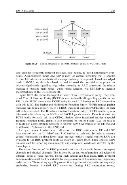
- Page 347 and 348: 328 UMTS Networks satisfy these req
- Page 349 and 350: 330 UMTS Networks Figure 10.29 Fram
- Page 351 and 352: 332 UMTS Networks MM connection pro
- Page 353 and 354: 334 UMTS Networks (a) (b) Figure 10
- Page 355 and 356: 336 UMTS Networks 10.5.1.3 Call Con
- Page 357 and 358: 338 UMTS Networks 10.5.1.2). After
- Page 359 and 360: 340 UMTS Networks (a) (b) Figure 10
- Page 361 and 362: 342 UMTS Networks (a) (b) Figure 10
- Page 363 and 364: Figure 10.38 User-plane protocol st
- Page 365 and 366: Table 6.3 Summary of IMS reference
- Page 367 and 368: 348 UMTS Networks Figure 10.39 Diam
- Page 370 and 371: 11 Procedure Examples Heikki Kaaran
- Page 372 and 373: Procedure Examples 353 After these
- Page 374 and 375: Procedure Examples 355 request sent
- Page 376 and 377: Procedure Examples 357 Figure 11.5
- Page 378 and 379: Procedure Examples 359 the QoS requ
- Page 380 and 381: Procedure Examples 361 Figure 11.9
- Page 382 and 383: Procedure Examples 363 Figure 11.12
- Page 384 and 385: Procedure Examples 365 Figure 11.14
- Page 386 and 387: Procedure Examples 367 the SRNC dis
- Page 388 and 389: Procedure Examples 369 updates the
- Page 390 and 391: Procedure Examples 371 As an acknow
- Page 392 and 393: Procedure Examples 373 11.3.2 URA U
- Page 394 and 395:
Procedure Examples 375 Figure 11.21
- Page 396 and 397:
Procedure Examples 377 Figure 11.22
- Page 398 and 399:
Procedure Examples 379 described ea
- Page 400 and 401:
Procedure Examples 381 Figure 11.24
- Page 402 and 403:
Procedure Examples 383 11.6.2 IMS S
- Page 404:
Procedure Examples 385 Figure 11.26
- Page 407 and 408:
388 List of Abbreviations AUTN An a
- Page 409 and 410:
390 List of Abbreviations DQPSK Dif
- Page 411 and 412:
392 List of Abbreviations IMPU IP M
- Page 413 and 414:
394 List of Abbreviations OLPC Open
- Page 415 and 416:
396 List of Abbreviations RTS Reque
- Page 417 and 418:
398 List of Abbreviations UBR Unspe
- Page 419 and 420:
400 Bibliography 2. Other Literatur
- Page 421 and 422:
402 UMTS Networks Code (cont.) Mana
- Page 423 and 424:
404 UMTS Networks Node B Applicatio
- Page 425:
406 UMTS Networks EDGE technology 9