ICM271 Fan Control Center - Patriot Supply
ICM271 Fan Control Center - Patriot Supply
ICM271 Fan Control Center - Patriot Supply

You also want an ePaper? Increase the reach of your titles
YUMPU automatically turns print PDFs into web optimized ePapers that Google loves.
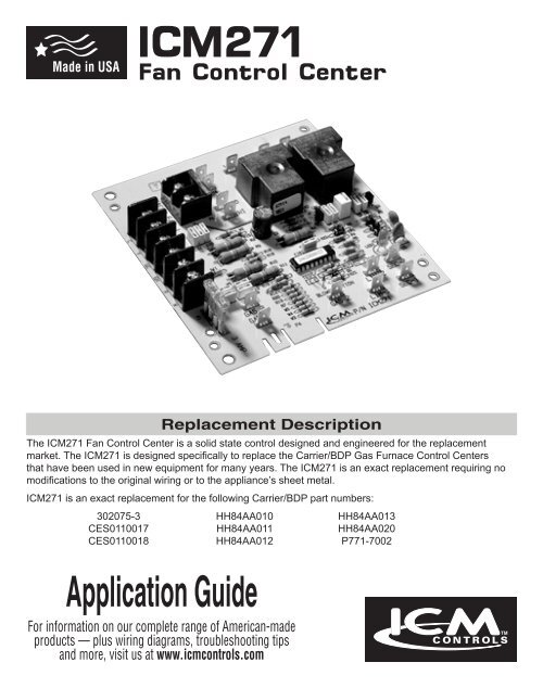
<strong>ICM271</strong><br />
<strong>Fan</strong> <strong>Control</strong> <strong>Center</strong><br />
Replacement Description<br />
The <strong>ICM271</strong> <strong>Fan</strong> <strong>Control</strong> <strong>Center</strong> is a solid state control designed and engineered for the replacement<br />
market. The <strong>ICM271</strong> is designed specifically to replace the Carrier/BDP Gas Furnace <strong>Control</strong> <strong>Center</strong>s<br />
that have been used in new equipment for many years. The <strong>ICM271</strong> is an exact replacement requiring no<br />
modifications to the original wiring or to the appliance’s sheet metal.<br />
<strong>ICM271</strong> is an exact replacement for the following Carrier/BDP part numbers:<br />
302075-3 HH84AA010 HH84AA013<br />
CES0110017 HH84AA011 HH84AA020<br />
CES0110018 HH84AA012 P771-7002<br />
Application Guide<br />
For information on our complete range of American-made<br />
products — plus wiring diagrams, troubleshooting tips<br />
and more, visit us at www.icmcontrols.com
Table of Contents<br />
Specifications........................................................................................................... 1<br />
Pre-installation Instructions ..................................................................................... 1<br />
Operational Differences ........................................................................................... 2<br />
Blower Speed Options ............................................................................................. 2<br />
Installation Instructions............................................................................................ 3<br />
Wiring Diagram......................................................................................................... 4<br />
<strong>ICM271</strong> Gas Furnace <strong>Control</strong> <strong>Center</strong> Component Layout ........................................ 5
Specifications<br />
• Input Voltage<br />
- Terminals: PR-1, PR-2, L1 and L2...................................................... 120 VAC<br />
- Terminals: SEC-1 and SEC-2 .......................................................... 18-30 VAC<br />
• Line Frequency.........................................................................................60 Hz<br />
• Operating Temperature...........................................................-40ºF to +176ºF<br />
• Maximum Operating Humidity........................................................... 95% R.H.<br />
Non-condensing @ 50ºC<br />
• Time Delays<br />
- Heat ON ....................................................................................... 75 Seconds<br />
- Heat OFF ................................................................................... 105 Seconds<br />
- Cool OFF ...................................................................................... 90 Seconds<br />
Pre-installation Instructions<br />
• Turn off gas supply and electrical power to equipment before servicing<br />
CAUTION!: This device should be installed by a qualified technician with due<br />
regard for safety as improper installation could result in hazardous<br />
conditions.<br />
CAUTION!: Failure to carefully read and follow these instructions before<br />
servicing or operating this control, could result in personal injury,<br />
death and/or property damage.<br />
CAUTION!: Do not short out terminals on the gas valve or the ignition<br />
control module. A short or incorrect wiring will burn out the<br />
thermostat heat anticipator. It could also result in personal<br />
injury, death and/or property damage.<br />
1
Operational Differences<br />
The <strong>ICM271</strong> has the same features and functions as the current Carrier/BDP<br />
replacement (HH84AA020). The <strong>ICM271</strong> has additional optional features and some<br />
slight operational differences than the older obsolete Carrier/BDP units. These<br />
options and operational differences are listed below.<br />
Note: Some older Carrier models did not have a cooling fan relay.<br />
1. On older Carrier/BDP models, the low-speed blower would still function if the 24<br />
volt transformer malfunctions. This will not happen with the <strong>ICM271</strong>.<br />
2. If the JW1 jumper is cut, a constant low-speed blower will occur without any<br />
thermostat signal. Also, a signal applied to the GC or Y terminals will not bring<br />
on the hi-speed blower during the cooling mode. Therefore, the JW1 jumper<br />
must not be cut on cooling applications.<br />
3. The 24 volt circuit is fuse protected which is not true on earlier Carrier/BDP<br />
models. A 3 amp automotive type fuse is used to protect the thermostat and<br />
transformer circuits from shorts.<br />
Note: On the <strong>ICM271</strong>, a blown fuse will cause the lo-speed blower to come on<br />
and remain on until the fuse has been replaced.<br />
4. The <strong>ICM271</strong> has an easy-to-remove vent damper jumper plug. This jumper plug<br />
is factory assembled for use on applications not having a vent damper. If the<br />
application has a vent damper, remove the jumper plug and connect the vent<br />
damper wiring harness connector to the <strong>ICM271</strong> circuit board.<br />
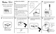
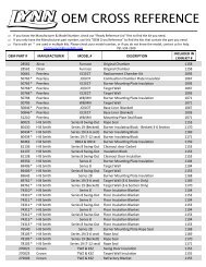
The GAS1-to-GAS3 connection is made<br />
by a three-wire flame-proof switch,<br />
but in some standing-pilot applications<br />
this device is not present. In such<br />
applications, a jumper must be installed<br />
between GAS1 and GAS3 terminals.<br />
A jumper should only be used on<br />
applications where a jumper exists on<br />
the previous furnace fan control board.<br />
This jumper should also include a male<br />
1/4” spade connector to connect to your<br />
current gas valve’s wiring harness.<br />
Blower Speed Options<br />
2<br />
W<br />
GAS3<br />
GAS1<br />
• Turn off gas supply and electrical power to equipment before servicing<br />
CAUTION!: Do not use this option on paired furnace applications.<br />
To<br />
Gas<br />
Valve<br />
The <strong>ICM271</strong> has different blower speed options to match a specific application (see<br />
chart on Page 3). The blower speed option used on the original furnace control may<br />
be very difficult to determine.<br />
1. On older Carrier/BDP models, the low-speed blower would still function if the 24<br />
volt transformer malfunctions. This will not happen with the <strong>ICM271</strong>.
2. If the old Carrier/BDP unit has large clear plastic relays and you cannot determine<br />
the blower speed option, leave the <strong>ICM271</strong> “as is.”<br />
3. Y from the thermostat and the outdoor unit must be connected to the <strong>ICM271</strong> Y<br />
terminal to get the hi-speed blower on a R-Y call.<br />
Determine which option matches your original control and proceed as directed.<br />
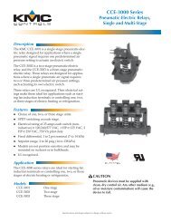
Using the component layout drawing (see Page 5), locate the G blower option (R17<br />
resistor). Cut the R17 resistor to achieve hi-speed continuous blower with a 90<br />
second OFF delay, with a thermostat signal to R-Y (call for cooling).<br />
Note: A good rule of thumb is not to cut any jumper or resistor unless it was<br />
cut on the old board.<br />
Input From<br />
Thermostat<br />
W<br />
<strong>ICM271</strong><br />
As Shipped<br />
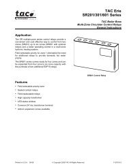
Blower Operating Modes<br />
Installation Instructions<br />
1. Be sure all electrical power is turned off.<br />
2. Remove control box cover, exposing the old Carrier/BDP gas furnace control<br />
center.<br />
3. If furnace is equipped with a vent damper, disconnect the plug connector from<br />
the old board.<br />
4. Tag each wire as it is disconnected from the old furnace control center.<br />
Disconnect all of the wiring hookups.<br />
5. Remove the old Carrier/BDP furnace control center from the control box.<br />
6. Install the <strong>ICM271</strong> fan control center into the control center box. Be sure the top<br />
edge of the <strong>ICM271</strong> is in the mounting slot, just like the original board.<br />
Note: If the <strong>ICM271</strong> is not installed correctly (i.e. behind the slot), an electrical<br />
short could occur.<br />
7. Reconnect all of the wires (removed in Step 4, above) to the proper terminals.<br />
8. If the appliance had a vent damper, break the vent damper jumper plug from the<br />
<strong>ICM271</strong>. Connect the original vent damper plug onto the <strong>ICM271</strong>.<br />
9. Restore electrical power to the furnace and put the furnace into operation.<br />
Allow the furnace to run through one complete heating or cooling cycle.<br />
10. If the furnace is functioning properly, replace all panels and leave this instruction<br />
sheet with the homeowner.<br />
3<br />
G Blower Operation<br />
(Cut R17 Resistor)<br />
Lo-Speed Heating Blower with<br />
75 seconds ON Delay and 105 seconds OFF Delay<br />
G High-speed cooling blower Lo-speed heating blower<br />
Y No blower Hi-speed cooling blower with 90 second OFF delay
R<br />
GH<br />
W<br />
VDP<br />
GC<br />
Y<br />
C<br />
�BVSS<br />
�AUXLS<br />
ITLK<br />
LINE-1<br />
JW-1<br />
BLWR<br />
LS<br />
LIM-2<br />
EAC-1<br />
FL<br />
HI/LO<br />
LIM-1<br />
EAC-2<br />
FUSE<br />
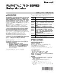
Wiring Diagram<br />
LO<br />
HI<br />
PR-1 PR-2<br />
115 VAC<br />
SEC-1<br />
MTR<br />
4<br />
TRANS<br />
MICROPROCESSOR<br />
LINE-2<br />
�CAP<br />
COM<br />
24 VAC SEC-2<br />
BLWR<br />
HI/LO<br />
GAS1 GAS2 GAS3<br />
Legend:<br />
AUXLS Auxiliary limit<br />
switch, manual<br />
reset (SPST-NC)<br />
(Down flow furnace<br />
models only)<br />
BLWR Blower motor relay<br />
(SPST-NO)<br />
BVSS Blocked vent shutoff<br />
switch, manual<br />
reset (SPST-NC)<br />
CAP Run capacitor<br />
FL Fusible link<br />
HI/LO Blower motor speed<br />
change relay (DPST)<br />
ITLK Blower door<br />
interlock switch<br />
(SPST-NO)<br />
LS Limit switch auto<br />
reset (SPST-NC)<br />
MTR Motor Blower<br />
TRANS Transformer<br />
VDP Vent damper jumper<br />
plug<br />
�<br />
Printed circuit<br />
board terminal<br />
24 VAC wiring<br />
115 VAC wiring<br />
Circuit on printed<br />
circuit board<br />
Screw terminal<br />
Equipment<br />
ground<br />
Not on all furnace<br />
models
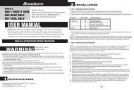
<strong>ICM271</strong> Gas Furnace <strong>Control</strong> <strong>Center</strong> Component Layout<br />
L2 L1 PR-1<br />
PR-2<br />
COM<br />
SPCB-1<br />
PCB500-1<br />
1<br />
Blower Relays<br />
NC<br />
FROM-C<br />
NO<br />
C<br />
EAC-2 EAC-1<br />
C<br />
P1<br />
NO<br />
C<br />
LO<br />
1<br />
C<br />
P2<br />
HI<br />
Y<br />
Y<br />
COIL<br />
COIL<br />
K1<br />
K2<br />
GC<br />
GC<br />
CR6<br />
W2<br />
R15<br />
D1<br />
Z1<br />
R2<br />
C10<br />
C11<br />
C12<br />
CR7<br />
C5 C2<br />
C4<br />
Q1<br />
C3<br />
R8<br />
Wall Thermostat<br />
Terminal Block<br />
R9<br />
Q2<br />
C7 C6<br />
R1<br />
JW-1<br />
R5<br />
R3<br />
CR5<br />
R16<br />
R18<br />
R22<br />
GH R W<br />
GH R W<br />
5<br />
CR4<br />
R4<br />
R6<br />
C16<br />
R10<br />
CR2<br />
W6<br />
6<br />
CR1<br />
CR3 C1<br />
M1<br />
U1<br />
R11<br />
JW-1<br />
R21<br />
R19<br />
C13<br />
C9<br />
C8<br />
C14<br />
R23<br />
R17<br />
R24<br />
TEST<br />
R12<br />
R14<br />
R20<br />
R13<br />
R7<br />
W5<br />
W4<br />
W3<br />
F1<br />
STATUS<br />
C15<br />
D2<br />
R25<br />
G<br />
BLOWER OPTION<br />
GAS3<br />
SEC-2<br />
LIM-2<br />
GAS1<br />
GAS2<br />
1<br />
SEC-1<br />
LIM-1<br />
P4<br />
C8<br />
C8<br />
C8<br />
3 AMP<br />
C8<br />
ATO 3-amp Fuse<br />
Blower<br />
Option<br />
Vent<br />
Damper<br />
Plug<br />
Connection<br />
Vent<br />
Damper
6333 Daedalus Drive, Cicero, NY 13039<br />
(Phone) 315-233-5266 (Toll Free) 800-365-5525 (Fax) 315-233-5276<br />
LIA163<br />
www.icmcontrols.com