
Create successful ePaper yourself
Turn your PDF publications into a flip-book with our unique Google optimized e-Paper software.
2 <strong>Clutch</strong> <strong>and</strong> <strong>release</strong> <strong>system</strong><br />
Figure 17 Work redistribution in clutch operation<br />
dual effect can thus be achieved by this redistribution:<br />
the realization of a harmonic load characteristic<br />
<strong>and</strong> the reduction of the maximum<br />
pedal load.<br />
The technical solution is a variable ratio for<br />
clutch operation. At low pedal loads the ratio<br />
is reduced <strong>and</strong> at high pedal loads it is raised.<br />
A clutch <strong>system</strong> with clutch, hydraulics <strong>and</strong><br />
pedal provides three possibilities for variation.<br />
Installation space <strong>and</strong> tolerance sensitivity<br />
argue against a design implementation<br />
inside the clutch. At LuK, therefore, the “variable<br />
hydraulic ratio” <strong>and</strong> “variable pedal<br />
ratio” concepts are being pursued.<br />
Variable hydraulic ratio<br />
The hydraulic ratio is calculated from the<br />
slave to master cylinder area ratio. This<br />
means that the variability can be achieved<br />
by changing one of the two areas as a function<br />
of the piston stroke. Because of the tolerance<br />
<strong>and</strong> wear situation of the clutch <strong>system</strong>,<br />
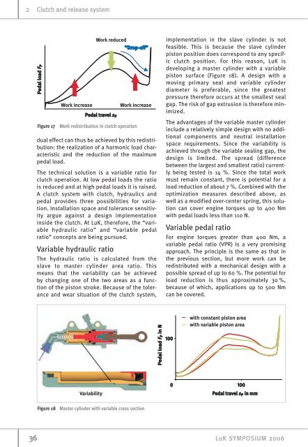
Figure 18 Master cylinder with variable cross section<br />
implementation in the slave cylinder is not<br />
feasible. This is because the slave cylinder<br />
piston position does correspond to any specific<br />
clutch position. For this reason, LuK is<br />
developing a master cylinder with a variable<br />
piston surface (Figure 18). A design with a<br />
moving primary seal <strong>and</strong> variable cylinder<br />
diameter is preferable, since the greatest<br />
pressure therefore occurs at the smallest seal<br />
gap. The risk of gap extrusion is therefore minimized.<br />
The advantages of the variable master cylinder<br />
include a relatively simple design with no additional<br />
components <strong>and</strong> neutral installation<br />
space requirements. Since the variability is<br />
achieved through the variable sealing gap, the<br />
design is limited. The spread (difference<br />
between the largest <strong>and</strong> smallest ratio) currently<br />
being tested is 14 %. Since the total work<br />
must remain constant, there is potential for a<br />
load reduction of about 7 %. Combined with the<br />
optimization measures described above, as<br />
well as a modified over-center spring, this solution<br />
can cover engine torques up to 400 Nm<br />
with pedal loads less than 110 N.<br />
Variable pedal ratio<br />
For engine torques greater than 400 Nm, a<br />
variable pedal ratio (VPR) is a very promising<br />
approach. The principle is the same as that in<br />
the previous section, but more work can be<br />
redistributed with a mechanical design with a<br />
possible spread of up to 60 %. The potential for<br />
load reduction is thus approximately 30 %,<br />
because of which, applications up to 500 Nm<br />
can be covered.<br />
36 LuK SYMPOSIUM 2006