
Create successful ePaper yourself
Turn your PDF publications into a flip-book with our unique Google optimized e-Paper software.
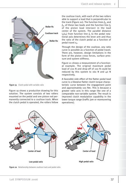
Figure 19 <strong>Clutch</strong> pedal with variable ratio<br />
Figure 19 shows a production drawing for this<br />
solution. The <strong>system</strong> consists of two rollers<br />
mounted on the pedal <strong>and</strong> one piston rod permanently<br />
connected to a coulisse track. When<br />
the clutch pedal is operated, the rollers follow<br />
Figure 20 Relationship between coulisse track <strong>and</strong> pedal ratio<br />
LuK SYMPOSIUM 2006<br />
<strong>Clutch</strong> <strong>and</strong> <strong>release</strong> <strong>system</strong> 2<br />
the coulisse track, with each of the two rollers<br />
able to support a load that is perpendicular to<br />
the track (Figure 20). The function lines fR1 <strong>and</strong><br />
fR2 of these two loads <strong>and</strong> the function line fK of the piston load intersect in the load<br />
center of the <strong>system</strong>. The parallel distance<br />
lH(sP) from function line fK to the pedal rotational<br />
axis determines the lever arm <strong>and</strong> thus<br />
the ratio of the clutch pedal as a function of<br />
pedal travel sP. Through the design of the coulisse, any ratio<br />
curve is possible as a function of pedal travel.<br />
There are, however, design limitations in the<br />
form of the piston cross forces, surface pressure<br />
<strong>and</strong> <strong>system</strong> stiffness.<br />
Figure 21 shows a measurement of a functional<br />
example. The original maximum pedal<br />
load of 200 N <strong>and</strong> drop-off of 100 N could be<br />
reduced by this <strong>system</strong> to 160 N <strong>and</strong> 40 N<br />
respectively.<br />
A favorable side effect of the flatter pedal load<br />
curve is a likewise flatter clutch torque characteristic<br />
curve between the engagement point<br />
<strong>and</strong> approximately 100 Nm. This is because a<br />
greater ratio acts in this range like one of a<br />
comparable non-variable <strong>system</strong>. The result is<br />
improved clutch modulation capability in the<br />
lower torque range (traffic jam or maneuvering<br />
operations).<br />
37