
Create successful ePaper yourself
Turn your PDF publications into a flip-book with our unique Google optimized e-Paper software.
2 <strong>Clutch</strong> <strong>and</strong> <strong>release</strong> <strong>system</strong><br />
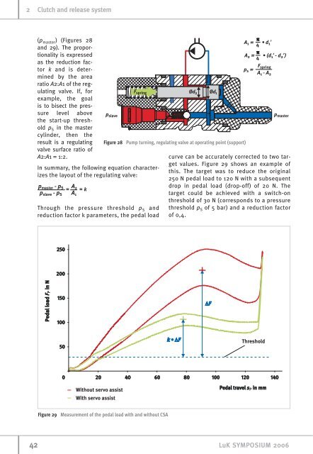
(pmaster) (Figures 28<br />
<strong>and</strong> 29). The proportionality<br />
is expressed<br />
as the reduction factor<br />
k <strong>and</strong> is determined<br />
by the area<br />
ratio A2:A1 of the regulating<br />
valve. If, for<br />
example, the goal<br />
is to bisect the pressure<br />
level above<br />
the start-up threshold<br />
pS in the master<br />
cylinder, then the<br />
result is a regulating<br />
valve surface ratio of<br />
A2:A1 = 1:2.<br />
In summary, the following equation characterizes<br />
the layout of the regulating valve:<br />
Through the pressure threshold p S <strong>and</strong><br />
reduction factor k parameters, the pedal load<br />
Figure 28 Pump turning, regulating valve at operating point (support)<br />
Figure 29 Measurement of the pedal load with <strong>and</strong> without CSA<br />
curve can be accurately corrected to two target<br />
values. Figure 29 shows an example of<br />
this. The target was to reduce the original<br />
250 N pedal load to 120 N with a subsequent<br />
drop in pedal load (drop-off) of 20 N. The<br />
target could be achieved with a switch-on<br />
threshold of 30 N (corresponds to a pressure<br />
threshold p S of 5 bar) <strong>and</strong> a reduction factor<br />
of 0,4.<br />
42 LuK SYMPOSIUM 2006