
Create successful ePaper yourself
Turn your PDF publications into a flip-book with our unique Google optimized e-Paper software.
2 <strong>Clutch</strong> <strong>and</strong> <strong>release</strong> <strong>system</strong><br />
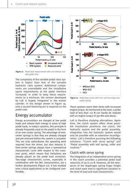
Figure 21 Pedal load measurement with <strong>and</strong> without variable<br />
pedal ratio<br />
The complexity of the variable pedal ratio <strong>system</strong><br />
is higher than that of the variable<br />
hydraulic ratio <strong>system</strong>. Additional components<br />
are unavoidable <strong>and</strong> the installation<br />
space requirements at the pedal interface<br />
increased. In order to keep these requirements<br />
to a minimum, the version developed<br />
by LuK is largely integrated in the master<br />
cylinder. In the design shown in Figure 19,<br />
only a second fastening pin is required on the<br />
pedal side.<br />
Energy accumulator<br />
Energy accumulators are charged at low pedal<br />
loads <strong>and</strong> <strong>release</strong> their energy in areas of high<br />
pedal loads. In today's <strong>system</strong>s, this principle is<br />
already frequently used on the pedal in the form<br />
of an over-center spring. The advantage of overcenter<br />
springs is that they are already charged<br />
<strong>and</strong> pre-stressed before the <strong>system</strong> is actuated.<br />
This not only redistributes the operating work<br />
required from the driver, but also reduces it.<br />
Over-center springs always have a symmetrical<br />
characteristic curve with respect to the crossover<br />
point, which means that limitations are<br />
already placed on the pedal load correction.<br />
Two-stage characteristic curves, especially in<br />
combination with the SAC characteristics, are a<br />
further development (Figure 22). It has enabled<br />
even critical applications to be configured comfortably.<br />
Figure 22 Pedal load curves with one- <strong>and</strong> two-stage overcenter<br />
spring<br />
These <strong>system</strong>s reach their limits with increased<br />
engine torque. As mentioned at the start, a pedal<br />
load of less than 110 N can hardly be realized<br />
with an engine torque of 350 Nm <strong>and</strong> above.<br />
LuK is therefore studying alternatives. Again<br />
here, the clutch <strong>system</strong> offers three possible<br />
installation positions: the clutch, the<br />
hydraulic <strong>system</strong> <strong>and</strong> the pedal assembly.<br />
Integration into the hydraulic <strong>system</strong> would<br />
only be possible with an extensive reconfiguration.<br />
LuK is therefore pursuing the following<br />
solutions: “<strong>Clutch</strong> with servo spring” <strong>and</strong><br />
“Pedal assembly with leaf spring, roller <strong>and</strong><br />
coulisse.”<br />
<strong>Clutch</strong> with servo spring<br />
The integration of an independent servo spring<br />
in the clutch provides a potential pedal load<br />
reduction of up to 20 N. However, all the tolerances<br />
of the diaphragm spring finger height<br />
<strong>and</strong> clutch wear lead to significant variation in<br />
the level of load <strong>and</strong> load characteristic.<br />
38 LuK SYMPOSIUM 2006