
Create successful ePaper yourself
Turn your PDF publications into a flip-book with our unique Google optimized e-Paper software.
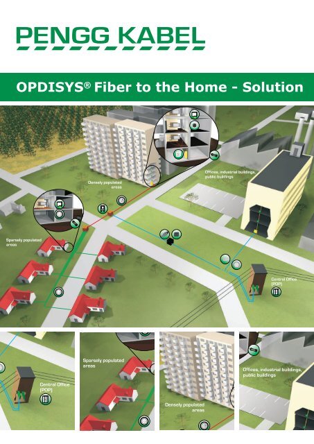
OPDISYS ® Fiber <strong>to</strong> <strong>the</strong> Home - Solution
Optical distribution system<br />
OPDISYS ® -rack<br />
The OPDISYS ® -rack was specially designed for Fiber-To-The-Home (FTTH) applications. It is a modular system consisting of a basic rack, cable<br />
management, mandrel extension racks and gasblocker extension racks and <strong>fiber</strong> modules. Thanks <strong>to</strong> its design this system is very flexible. The<br />
extension racks can be ordered and combined individually according <strong>to</strong> <strong>the</strong> cus<strong>to</strong>mer´s needs. Each <strong>fiber</strong> module has a front plate with two<br />
types of uniform cut-out patterns in<strong>to</strong> which snap-in angled holders fitting in<strong>to</strong> <strong>the</strong> required adapter type can be inserted. This snap-in angled<br />
holder also ensures a 45 degree angle of <strong>the</strong> adapter is maintained. Each <strong>fiber</strong> module can be used as a left-side as well as a right-side <strong>fiber</strong><br />
module.<br />
By default, <strong>the</strong>re are protection tubes from <strong>the</strong> cable clamp <strong>to</strong> each individual module is installed by kink-resistant PBT-tubes. They ensure that<br />
<strong>the</strong> minimum curve radius of <strong>the</strong> cable loose tubes from <strong>the</strong> cable entry <strong>to</strong> <strong>the</strong> <strong>fiber</strong> modules will not be exceeded.<br />
The cable clamps are pre-installed ei<strong>the</strong>r on <strong>the</strong> <strong>to</strong>p or on <strong>the</strong> bot<strong>to</strong>m of <strong>the</strong> rack and are used <strong>to</strong> secure <strong>the</strong> strain relief of <strong>the</strong> incoming cables.<br />
They serve fur<strong>the</strong>r as a fixing point for <strong>the</strong> cable tubes. Optionally, <strong>the</strong> strain relief element of <strong>the</strong> incoming cable <strong>to</strong> be attached.<br />
Technical data:<br />
• maximum <strong>fiber</strong> density: 960 <strong>fiber</strong>s at SC,<br />
1920 <strong>fiber</strong>s at LC and E2000<br />
• comfortable patching with two-sided overlength<br />
patchcord s<strong>to</strong>rage<br />
• optional extensions (for cable guidance and<br />
gasblocker integration)<br />
• available as open and closed rack version<br />
• removable and rotatable splice/patch <strong>fiber</strong><br />
module<br />
• <strong>fiber</strong> module frontplate with different cu<strong>to</strong>uts<br />
and adapter mounting through snap-in<br />
angled holder available: SC, LC, E2000<br />
(o<strong>the</strong>rs on request)<br />
• optional integration of gas-blockers on<br />
incoming tubes possible (on request)<br />
• colour:<br />
RAL 7035, light grey<br />
• material: Powder coated steel<br />
• flammability: UL 94V-0<br />
The OPDISYS ® -rack is <strong>the</strong> core component of every OPDISYS ® -system. Both, an open version as well as a closed version, are available. An<br />
open version rack is turned in<strong>to</strong> a closed version rack by installing side panels and doors. The rack accommodates <strong>the</strong> <strong>fiber</strong> module carrier, <strong>the</strong><br />
cable entry plates, all types of extension modules and, if a closed version is required, <strong>the</strong> side panels as well as <strong>the</strong> front doors.<br />
Various fixing sets (see information in <strong>the</strong> accessories section of this document) are available which allow you <strong>to</strong> mount <strong>the</strong> rack <strong>to</strong> ei<strong>the</strong>r wall or<br />
ceiling or floor. It is possible <strong>to</strong> mount several racks next <strong>to</strong> each o<strong>the</strong>r back-<strong>to</strong>-back (requires only floor mounting) or next <strong>to</strong> each o<strong>the</strong>r (requires<br />
mounting both <strong>to</strong> floor and ceiling or wall for stability reasons). A stand-alone Single Row Rack should always be fixed <strong>to</strong> both floor and ceiling<br />
or wall.
Rack features:<br />
• <strong>to</strong>p or bot<strong>to</strong>m cable entry possible<br />
• <strong>to</strong>p cover provides openings for cables (optionally with brushes)<br />
• easy expansion with side-by-side or back-<strong>to</strong>-back mounting of racks<br />
• <strong>solution</strong>s for cross-connect and interconnect configurations<br />
• backside vertical cable guidance for incoming cables<br />
• bending radius protection of 30mm for <strong>fiber</strong>s and patchcords<br />
• intelligent patchcord management<br />
• vertical patchcord cable guidance on left and right side<br />
• mandrels on left and right side of <strong>the</strong> rack provide sufficient space for patchcord overlength s<strong>to</strong>rage<br />
• integrated patchcord management <strong>to</strong> adjacent racks avoids <strong>the</strong> usage of external ducts<br />
Dimensions & capacity -<br />
standard version (incl. mandrels)<br />
Rack height<br />
Rack width<br />
Rack weight (open / closed)<br />
Max. amount of modules<br />
Max. amount of terminations<br />
OPDISYS ® -rack 1000/40HU<br />
incl. mandrels, protective tubes<br />
OPDISYS ® -rack 1000/40HU<br />
2200 mm<br />
1000 mm<br />
118 kg / 170 kg<br />
80 Full-Size or 160 Half-Size<br />
960 SC<br />
1920 LC / E2000<br />
Art. No. 2735153<br />
OPDISYS ® -rack - possible extensions (on request)<br />
Gasblocker - extension rack<br />
When using blow-in systems, gasblockers are essential in order <strong>to</strong> protect <strong>the</strong> installation against gas<br />
and/or water entry. The gasblocker extension rack can accommodate <strong>the</strong> gasblockers. It has a built-in<br />
back panel, so no extra back panel is needed in order <strong>to</strong> turn it in<strong>to</strong> a closed version.<br />
Rack doors, side and back panels<br />
If a closed rack version is required, doors and panels can be attached <strong>to</strong> rack. Each door has an opening<br />
angle of 180°. The doors are equipped with an integrated lever and lock and have an A4 document holder<br />
on <strong>the</strong>ir inner side. Each side panel is useable for right as well as for left side mounting.<br />
Gasblocker - extension rack<br />
on request<br />
Panels / door set Art. No. 2735154<br />
OPDISYS ® Fiber <strong>to</strong> <strong>the</strong> Home - Solution • 02/2016 • © by Pengg Kabel GmbH • Technische Änderungen vorbehalten<br />
3
OPDISYS ® -rack - accessories<br />
Fixing sets<br />
Several fixing sets are available <strong>to</strong> mount <strong>the</strong> rack <strong>to</strong> <strong>the</strong> wall, on <strong>the</strong> floor or <strong>to</strong> mount multiple racks side<br />
by side or back <strong>to</strong> back <strong>to</strong> each o<strong>the</strong>r. Each individual fixing set contains all necessary screws, mounting<br />
brackets, washers and anchor pins.<br />
Tool kit<br />
• adapter holder pincer<br />
The adapter holder pincer is designed <strong>to</strong> easily remove <strong>the</strong> snap-in angled holder from <strong>the</strong> frontplate<br />
cu<strong>to</strong>ut of <strong>the</strong> OPDISYS ® <strong>fiber</strong> module. Thanks <strong>to</strong> its small and compact design it ensures <strong>the</strong> smooth<br />
removal of a snap-in angled holder without interfering with o<strong>the</strong>r connections.<br />
• <strong>to</strong>rx socket wrench<br />
• draw wire or element<br />
The draw wire or element <strong>to</strong>ol is necessary <strong>to</strong> insert <strong>the</strong> incoming <strong>fiber</strong> cable in<strong>to</strong> <strong>the</strong> <strong>fiber</strong> protection<br />
tube which is fed up <strong>to</strong> <strong>the</strong> <strong>fiber</strong> optic module. This <strong>to</strong>ol is required <strong>to</strong> install a OPDISYS ® -System.<br />
Fixing set, back-<strong>to</strong>-back or side-<strong>to</strong>-side Art. No. 2735155<br />
Fixing set for double bot<strong>to</strong>ms Art. No. 2735156<br />
Fixing set “base with leveling feet“ Art. No. 2735157<br />
Tool kit Art. No. 2735158<br />
OPDISYS ® -<strong>fiber</strong> modules<br />
The multi-circuit management <strong>fiber</strong> modules are used as combined splice & patch<br />
modules. They offer highest <strong>fiber</strong> density along with best maintainability. Maximum flexibility<br />
is guaranteed by metal frontplates and 45° angled adapter holders for all conventional<br />
adapter types. The <strong>fiber</strong> modules are available as full-size <strong>fiber</strong> modules with a height of<br />
1HU.<br />
Fiber modules can be equipped with different adapter types or with a closed frontplate<br />
without adapters for a splice-through version (in this case, a loop- back connection of<br />
<strong>fiber</strong>s can be done via splices).<br />
The material of <strong>the</strong> LSZH <strong>fiber</strong> modules is a Polycarbonate / ABS blend. The symmetrical<br />
design of <strong>the</strong> multi-circuit management <strong>fiber</strong> modules allows you <strong>to</strong> use <strong>the</strong> same module<br />
for left- and right-side mounting. A uniform module colour optimizes s<strong>to</strong>ck keeping, while<br />
individual threefold colour code labelling (on front, side and cover) provides fast and clear<br />
module and <strong>fiber</strong> identification. On request we can deliver each <strong>fiber</strong> module with a<br />
cus<strong>to</strong>mized labelling of <strong>the</strong> <strong>to</strong>p cover (index of all ports with description) as well as a<br />
labelling of <strong>the</strong> side of each Fiber Module (indication of <strong>the</strong> street and <strong>the</strong> building this<br />
module is assigned <strong>to</strong>) according <strong>to</strong> <strong>the</strong> cus<strong>to</strong>mer’s request. Also <strong>the</strong> labelling of <strong>the</strong> <strong>fiber</strong><br />
module numbering can be done by us.<br />
• <strong>fiber</strong> modules can be rotated by 90° and are removable from <strong>the</strong> rack<br />
• incoming <strong>fiber</strong>s and pigtails are s<strong>to</strong>red in separate areas<br />
• easy <strong>to</strong> snap in adapter holders allow comfortable cleaning of pigtail-connec<strong>to</strong>r<br />
ferrules by taking off <strong>the</strong> adapter holders.<br />
• identical splice protection holder for both shrink and crimp splice protection<br />
• two-sided, easy <strong>to</strong> remove transparent covers per <strong>fiber</strong> module<br />
• bending radius protection for all <strong>fiber</strong>s and pigtails<br />
• overlength s<strong>to</strong>rage of incoming cable subtube is possible on <strong>the</strong> bot<strong>to</strong>m side of <strong>the</strong><br />
module<br />
Technical Data:<br />
• Colour<br />
RAL 7035, light grey<br />
• Material<br />
Powder coated steel<br />
• Flammability UL 94V-0<br />
• Weight (full size module) 145 grams (without adapters and pigtails)<br />
Each Fiber Module is equipped with a frontplate, snap-in angled holders, rubber shrink/crimp splice protection holder, <strong>fiber</strong> protection pipe<br />
holder, two transparent covers, designation label, door latch and inserted adapters and pigtails.
Plug-in configuration - fully equipped<br />
SC LC E2000<br />
Amount of adapters 12 12 12<br />
Amount of pigtails 12 24 24<br />
Max. amount of spices<br />
Heat shrink splice protection*<br />
Crimp splice protection*<br />
Max. amount of spices 32 48<br />
* Heat shrink splice protection or crimp splice protection are not included and must be ordered separately.<br />
Fiber module 24 LC/APC, 1HU Art. No. 2535159<br />
Fiber module 24 E2000/APC, 1HU Art. No. 2535160<br />
Fiber module 12 SC/APC, 1HU Art. No. 2535161<br />
Fiber module for up <strong>to</strong> 48 splices, 1HU Art. No. 2535162<br />
Cable clamp set Art. No. 2735163<br />
OPDISYS ® Fiber <strong>to</strong> <strong>the</strong> Home - Solution • 02/2016 • © by Pengg Kabel GmbH • Technische Änderungen vorbehalten<br />
5
Patch cable<br />
PC LC/APC simplex, 2 mm<br />
Characteristics of LC/APC simplex:<br />
• user-friendly audible latch <strong>to</strong> indicate proper mating<br />
• push-pull locking<br />
• plastic housing with zirconia ferrule<br />
• standard IEC 61754-20<br />
• insertion loss (IL) for SM (typical)<br />
average value<br />
Fiber optic cable<br />
A-DQ(BN)2Y CT - Outdoor cable, center unitube, D35-S15<br />
outdoor cable<br />
rodent protection<br />
metal-free<br />
longitudinally<br />
water-tight<br />
A-DQ(BN)2Y CT 12E9/125 Art. No. 2035132<br />
A-DQ(BN)2Y CT 24E9/125 Art. No. 2035133<br />
Type number of numbers of tube-Ø tenisle strength outer-Ø weight<br />
<strong>fiber</strong>s / tube <strong>fiber</strong>s approx. mm max. N approx. mm approx. kg/km<br />
A-DQ(BN)2Y CT 12E9/125 12 12 3,5 2000 8,5 72,8<br />
A-DQ(BN)2Y CT 24E9/125 24 24 3,5 2000 8,5 73,7<br />
Central loose tube cable for outdoor applications. Rodent protected by glass rovings.<br />
This cable is used as low <strong>fiber</strong> count data cable in distribution networks and meets <strong>the</strong> demands of outdoor environments. Fibers according<br />
ITU-T G.652.D<br />
Construction<br />
center unitube<br />
strength members (aramide yarns)<br />
PE-sheath, UV-resistant, black with two orange longitudinal stripes<br />
Fiber colours<br />
1-12: red, green, yellow, blue, white, violet, orange, black, grey, brown, pink, turquoise<br />
13-24: red, green, yellow, blue, white, violet, orange, transparent, grey, brown, pink, turquoise -each with black rings every 50 mm (max.)<br />
Tube colour<br />
red<br />
Laying<br />
usable for fixed laying in ducts or conduits and outdoors<br />
Marking<br />
double-sinus, phone-sign, meter marking, PENGG KABEL, year of manufacturing<br />
Technical Data<br />
tensile strength:<br />
compressive strength:<br />
impact strength:<br />
<strong>to</strong>rsion:<br />
kink, cable:<br />
kink, tube:<br />
min. bending radius:<br />
temperature range:<br />
water penetration:<br />
according <strong>to</strong> IEC 60794-1-E1<br />
according <strong>to</strong> IEC 60794-1-E3 | value: 3000 N/10 cm<br />
according <strong>to</strong> IEC 60794-1-E4 | value: 5 Nm<br />
according <strong>to</strong> IEC 60794-1-E7 | value: 5 cycles ±1 turn<br />
according <strong>to</strong> IEC 60794-1-E10 | value: The cables do not form a kink when a loop is drawn <strong>to</strong>ge<strong>the</strong>r <strong>to</strong> a diameter<br />
of 100 mm.<br />
according <strong>to</strong> IEC 60794-1-E16 | value: The loose tubes do not kink.<br />
according <strong>to</strong> IEC 60794-1-E11 | value: R = 20 x D (cable outer diameter)<br />
according <strong>to</strong> IEC 60794-1-F1<br />
s<strong>to</strong>rage and transport: -40°C up <strong>to</strong> +70°C<br />
laying:<br />
-5°C up <strong>to</strong> +60°C<br />
operation:<br />
-25°C up <strong>to</strong> +70°C<br />
according <strong>to</strong> IEC 60794-1-F5 | value: No water on free end.<br />
OPDISYS ® Fiber <strong>to</strong> <strong>the</strong> Home - Solution • 02/2016 • © by Pengg Kabel GmbH • Technische Änderungen vorbehalten<br />
7
A-DQ(BN)2Y GGT - Outdoor cable, loose tube construction, D23-S20<br />
outdoor cable<br />
rodent protection<br />
metal-free<br />
longitudinally<br />
water-tight<br />
A-DQ(BN)2Y GGT 2x12E9/125 Art. No. 2035134<br />
A-DQ(BN)2Y GGT 4x12E9/125 Art. No. 2035135<br />
A-DQ(BN)2Y GGT 6x12E9/125 Art. No. 2035136<br />
A-DQ(BN)2Y GGT 8x12E9/125 Art. No. 2035137<br />
A-DQ(BN)2Y GGT 10x12E9/125 Art. No. 2035138<br />
A-DQ(BN)2Y GGT 12x12E9/125 Art. No. 2035139<br />
A-DQ(BN)2Y GGT 8x24 E9/125 Art. No. 2035140<br />
A-DQ(BN)2Y GGT 18x24E9/125 Art. No. 2035141<br />
Type number of number of tubes number of tube-Ø tensile strength outer-Ø weight<br />
<strong>fiber</strong>s/tube + fillers <strong>fiber</strong>s approx. mm max. N approx. mm approx. kg/km<br />
A-DQ(BN)2Y GGT 2x12E9/125 12 2 + 3 24 2,3 3500 13,2 141,7<br />
A-DQ(BN)2Y GGT 4x12E9/125 12 4 + 1 48 2,3 3500 13,2 145,3<br />
A-DQ(BN)2Y GGT 6x12E9/125 12 6 + 0 72 2,3 3500 13,5 160,0<br />
A-DQ(BN)2Y GGT 8x12E9/125 12 8 + 0 96 2,3 3500 14,8 182,5<br />
A-DQ(BN)2Y GGT 10x12E9/125 12 10 + 0 120 2,3 3500 16,3 214,0<br />
A-DQ(BN)2Y GGT 12x12E9/125 12 12 + 0 144 2,3 3500 18,0 251,0<br />
A-DQ(BN)2Y GGT 8x24E9/125 24 8 + 0 192 2,3 3500 16,5 221,8<br />
A-DQ(BN)2Y GGT 18x24E9/125 24 18 + 0 432 2,3 3500 20,5 335,4<br />
Stranded loose tube cable for outdoor applications. Highly rodent protected by 2 layers of glass rovings.<br />
This cable is used as higher <strong>fiber</strong> count data cable in distribution networks and withstands environments with high mechanical demands.<br />
Fibers according ITU-T G.652.D<br />
Construction<br />
FRP-central element<br />
loose tubes, SZ-cabling (if necessary with fillers)<br />
dry filled cable core<br />
strength members (glass-rovings)<br />
ripcord<br />
PE-sheath, UV-resistant, black with two orange longitudinal stripes<br />
Fiber colours<br />
1-12: red, green, yellow, blue, white, violet, orange, black, grey, brown, pink, turquoise<br />
13-24: red, green, yellow, blue, white, violet, orange, transparent, grey, brown, pink, turquoise -each with black rings every 50 mm (max.)<br />
Tube colours<br />
1: red<br />
2: green<br />
o<strong>the</strong>rs: nature or white<br />
Filler colours<br />
black<br />
Laying<br />
usable for fixed laying in ducts or conduits and outdoors<br />
Marking<br />
double-sinus, phone-sign, meter marking, PENGG KABEL, year of manufacturing<br />
Technical Data<br />
tensile strength:<br />
compressive strength:<br />
impact strength:<br />
<strong>to</strong>rsion:<br />
kink, cable:<br />
kink, loose tube:<br />
min. bending radius:<br />
temperature range:<br />
water penetration:<br />
according <strong>to</strong> IEC 60794-1-E1<br />
according <strong>to</strong> IEC 60794-1-E3 | value: 3000 N/10 cm<br />
according <strong>to</strong> IEC 60794-1-E4 | value: 10 Nm<br />
according <strong>to</strong> IEC 60794-1-E7 | value: 5 cycles ±1 turn<br />
according <strong>to</strong> IEC 60794-1-E10 | value: The cables do not form a kink when a loop is drawn <strong>to</strong>ge<strong>the</strong>r <strong>to</strong> a<br />
diameter 12 times <strong>the</strong> cable nominal diameter.<br />
according <strong>to</strong> IEC 60794-1-E16 | value: The loose tubes do not kink.<br />
according <strong>to</strong> IEC 60794-1-E11 | value: R = 20 x D (cable outer diameter)<br />
according <strong>to</strong> IEC 60794-1-F1<br />
s<strong>to</strong>rage and transport: -40°C up <strong>to</strong> +70°C<br />
laying:<br />
-5°C up <strong>to</strong> +60°C<br />
operation:<br />
-30°C up <strong>to</strong> +70°C<br />
according <strong>to</strong> IEC 60794-1-F5 | value: No water on free end.
A-DQ(ZN)2Y Mini T - Mini cable, loose tube construction, D15-S05<br />
outdoor cable<br />
metal-free<br />
longitudinally<br />
water-tight<br />
A-DQ(ZN)2Y Mini T 2x12E9/125 blue Art. No. 2035144<br />
A-DQ(ZN)2Y Mini T 4x12E9/125 red Art. No. 2035145<br />
A-DQ(ZN)2Y Mini T 6x12E9/125 violet Art. No. 2035146<br />
A-DQ(ZN)2Y Mini T 8x12E9/125 pink Art. No. 2035147<br />
A-DQ(ZN)2Y Mini T 12x12E9/125 grey Art. No. 2035148<br />
Type number of number of tubes tube-Ø tensile strength outer-Ø weight<br />
<strong>fiber</strong>s + fillers approx. mm max. N approx. mm approx. kg/km<br />
A-DQ(ZN)2Y Mini T 2x12E9/125 blue 24 2 + 4 1,5 700 5,6 29,1<br />
A-DQ(ZN)2Y Mini T 4x12E9/125 red 48 4 + 2 1,5 700 5,6 30,0<br />
A-DQ(ZN)2Y Mini T 6x12E9/125 violet 72 6 + 0 1,5 700 5,6 30,8<br />
A-DQ(ZN)2Y Mini T 8x12E9/125 pink 96 8 + 0 1,5 700 6,5 44,5<br />
A-DQ(ZN)2Y Mini T 12x12E9/125 grey 144 12 + 0 1,5 700 8,5 64,1<br />
Stranded mini tube cable for laying in<strong>to</strong> micro ducts.<br />
This cable is used in access networks as both connection between <strong>fiber</strong> distributers and house connection for multi dwelling units. Fibers<br />
according ITU-T G.657.A1.<br />
Due <strong>to</strong> both <strong>the</strong> deployed <strong>fiber</strong>s and its light construction it is suitable for small bending radii.<br />
Construction<br />
central member, metal free<br />
loose buffer tube filled with a thixotropic gel, swellable aramid yarns<br />
dry filled cable core<br />
rip cord<br />
PE-sheath<br />
Fiber colours<br />
1-12: red, green, yellow, blue, white, violet, orange, black, grey, brown, pink, turquoise<br />
Tube colours<br />
1: red<br />
2: green<br />
o<strong>the</strong>rs: nature or white<br />
Filler colours<br />
black<br />
Marking<br />
double-sinus, phone-sign, meter marking, PENGG KABEL, year of manufacturing<br />
Technical Data<br />
tensile strength: according <strong>to</strong> IEC 60794-1-E1<br />
compressive strength: according <strong>to</strong> IEC 60794-1-E3 | value: 1000 N/10 cm<br />
impact strength: according <strong>to</strong> IEC 60794-1-E4 | value: 5 Nm (3 impacts, 300 mm hammer radius)<br />
min. bending radius: according <strong>to</strong> IEC 60794-1-E11 | values: static R = 10 x D, dynamic R = 20 x D (cable outer diameter)<br />
temperature range: according <strong>to</strong> IEC 60794-1-F1<br />
s<strong>to</strong>rage and transport -30°C up <strong>to</strong> +60°C<br />
laying<br />
-5°C up <strong>to</strong> +50°C<br />
operation<br />
-30°C up <strong>to</strong> +60°C<br />
water penetration: according <strong>to</strong> IEC 60794-1-F5 | value: ≤1 m (0,1 bar, 24 h)<br />
OPDISYS ® Fiber <strong>to</strong> <strong>the</strong> Home - Solution • 02/2016 • © by Pengg Kabel GmbH • Technische Änderungen vorbehalten<br />
9
A-DQ(ZN)2Y Mini CT - Mini cable, central unitube, D30-S04<br />
outdoor cable<br />
metal-free<br />
longitudinally<br />
water-tight<br />
A-DQ(ZN)2Y Mini CT 12E9/125 yellow Art. No. 2035142<br />
A-DQ(ZN)2Y Mini CT 24E9/125 blue Art. No. 2035143<br />
Type number of number of tube-Ø Zugfestigkeit outer-Ø weight<br />
<strong>fiber</strong>s/tube <strong>fiber</strong>s approx. mm max. N approx. mm approx. kg/km<br />
A-DQ(ZN)2Y Mini CT 12E9/125 yellow 12 12 3,0 400 3,9 12,9<br />
A-DQ(ZN)2Y Mini CT 24E9/125 blue 24 24 3,0 400 3,9 13,8<br />
Central mini tube cable for laying in<strong>to</strong> micro ducts.<br />
This cable is used in access networks as drop cable <strong>to</strong> house connections. Fibers according ITU-T G.657.A1. Due <strong>to</strong> both <strong>the</strong> deployed<br />
<strong>fiber</strong>s and its light construction it is suitable for small bending radii.<br />
Construction<br />
center unitube<br />
strength members (aramide yarns)<br />
PE-sheath<br />
Fiber colours<br />
1-12: red, green, yellow, blue, white, violet, orange, black, grey, brown, pink, turquoise<br />
13-24: red, green, yellow, blue, white, violet, orange, transparent, grey, brown, pink, turquoise -each with black rings every 50 mm (max.)<br />
Tube colour<br />
red<br />
Marking<br />
double-sinus, phone-sign, meter marking, PENGG KABEL, year of manufacturing<br />
Technical Data<br />
tensile strength:<br />
compressive strength:<br />
impact strength:<br />
min. bending radius:<br />
temperature range:<br />
according <strong>to</strong> IEC 60794-1-E1<br />
according <strong>to</strong> IEC 60794-1-E3 | value: 1000 N/10 cm<br />
according <strong>to</strong> IEC 60794-1-E4 | value: 1 Nm (3 impacts, 300 mm Hammer radius)<br />
according <strong>to</strong> IEC 60794-1-E11 | value: static R = 20 x D (cable outer diameter)<br />
according <strong>to</strong> IEC 60794-1-F1<br />
s<strong>to</strong>rage and transport -30°C up <strong>to</strong> +70°C<br />
laying<br />
-5°C up <strong>to</strong> +50°C<br />
operation<br />
-20°C up <strong>to</strong> +70°C
I-VQ(ZN)H 4E9/125 FTTH-Inhouse cable - Inhouse cable, V06<br />
inhouse cable<br />
metal-free<br />
halogenfree,<br />
flame retardant<br />
I-VQ(ZN)H 4E9/125 FTTH-Inhouse cable Art. No. 2035149<br />
Type number of tube-Ø number of tubes tensile strength *) outer-Ø weight<br />
<strong>fiber</strong>s approx. µm + fillers max. N approx. mm approx. kg/km<br />
I-VQ(ZN)H 4E9/125 FTTH-Inhouse cable 4 600 4 + 0 400 2.8 7,5<br />
*) with reversible attenuation increase<br />
FTTH in-house cable, suitable for laying within buildings in both horizontal and vertical ways.<br />
This cable is suitable for direct assembling with connec<strong>to</strong>rs. Fibers according ITU-T G.657.A1.<br />
Construction<br />
4 buffered <strong>fiber</strong>s (silikon-coated, 600 microns)<br />
strength members (aramide yarns)<br />
FRNC-sheath according <strong>to</strong> IEC 60332-3, UV-resistant<br />
Fiber colours<br />
red, green, yellow, blue<br />
Mantelfarbe<br />
grey<br />
Marking<br />
letter symbol of <strong>fiber</strong> type, meter marking, PENGG KABEL, year of manufacturing<br />
Technical Data<br />
standard: IEC 60794<br />
tensile strength: according <strong>to</strong> IEC 60794-1-E1<br />
compressive strength: according <strong>to</strong> IEC 60794-1-E3 | value: 500 N/10 cm<br />
bending radius: static 15 x cable outer diameter<br />
dynamic 20 x cable outer diameter<br />
temperature range: s<strong>to</strong>rage and transport -25°C up <strong>to</strong> +70 °C<br />
laying -5°C up <strong>to</strong> +50 °C<br />
operation -5°C up <strong>to</strong> +50 °C<br />
OPDISYS ® Fiber <strong>to</strong> <strong>the</strong> Home - Solution • 02/2016 • © by Pengg Kabel GmbH • Technische Änderungen vorbehalten<br />
11
Fiber optic enclosure<br />
SEC15 for max. 128 splices<br />
Description<br />
• The SEC15 dome enclosure is particularly suitable for connecting fibre optic cables featuring a small number of fibres<br />
• Enclosure for in-line connections and branch-offs<br />
• Suitable for underground, duct, wall and pole/<strong>to</strong>wer mounting<br />
• Suitable for uncut cables<br />
• Assembly/disassembly of <strong>the</strong> dome without any <strong>to</strong>ols<br />
• Sealings can be used again<br />
• Separate strain relief points for central strength member and Kevlar reinforcement<br />
• S<strong>to</strong>rage of cut/uncut multi-fibre loose tubes<br />
• Cable entries for max.<br />
1 oval entry for 2x10-25 mm cables<br />
3 entries for 10-20 mm cables<br />
• Splice cassettes (order separate) 8 x SK120S<br />
• Degree of protection<br />
>IP68<br />
• Max. splice capacity<br />
Splice protection tube 128<br />
• Tests according <strong>to</strong> DIN 47624 Draft 4/97<br />
Mechanical strength<br />
Load (15 min)<br />
1000 N at <strong>the</strong> centre of <strong>the</strong> enclosure,<br />
contact area 5 cm 2<br />
Impact (once)<br />
1 kg Steel ball, 2 m fall,<br />
at <strong>the</strong> centre of <strong>the</strong> enclosure<br />
Pressure resistance<br />
Permanent pressure<br />
0.4 bar above atmospheric<br />
Tight from<br />
-40°C <strong>to</strong> +70C°<br />
Tightness with cable<br />
Strain (15 min)<br />
1000 N<br />
Shearing/bending (twice)<br />
Deflection 45° or a max. of 500 N bending force,<br />
Point of application 250 mm from cable entry<br />
Torsion (twice)<br />
±90° rotation angle or a max. <strong>to</strong>rque of 50 Nm,<br />
Point of application 500 mm from cable entry<br />
Vibration<br />
168 hours; both cable ends fastened,<br />
Amplitude ±3 mm, frequency 10 Hz<br />
Temperature changes<br />
-40°C <strong>to</strong> +70°C, 10 times<br />
Immersion in wetting agent<br />
168 hours<br />
External pressure resistance<br />
4 m water column<br />
Water vapour permeation
SEC23 Tubeless short for max. 288 / 432 splices<br />
Description<br />
• Tubeless version suitable especially for Single Circuit (SC) and Single Element (SE).<br />
Single Circuit: Distribution of <strong>the</strong> fibres from one multi-fibre loose tube <strong>to</strong> several splice cassettes through fibre guiding channels<br />
• Tubeless laying of <strong>the</strong> fibres from entry <strong>to</strong> splice cassette<br />
• In-line connection and branch-off enclosure<br />
• Suitable for ground, duct, wall, pole and <strong>to</strong>wer mounting<br />
• “Short” version especially for manholes or cable ducts<br />
• Suitable for uncut cables<br />
• Assembly/disassembly of <strong>the</strong> dome without any <strong>to</strong>ols<br />
• Sealings can be used again<br />
• Separate strain relief points for central strength member and Kevlar reinforcement<br />
• An entry module permits fibre guidance <strong>to</strong> any desired cassette entry<br />
• Cable entries for max.<br />
1 oval entry for 2x10-25 mm cables<br />
4 entries for 10-20 mm cables<br />
2 entries for 10-25 mm cables<br />
• Splice cassettes (order separate) 36 x SK123 (SE) or SK223 (SC)<br />
Available in cassette sets of 6 splice cassettes each ⇒ max. 6 sets (3 units on ei<strong>the</strong>r side).<br />
Splice cassettes engaged in a slanted position<br />
Pivoting splice cassettes (90°) <strong>to</strong> provide easy access <strong>to</strong> each splice<br />
• Degree of protection<br />
>IP68<br />
• Max. splice capacity<br />
2x4 splices at each SK223 (SC) 288<br />
12 splices at each SK123 (SE) 432<br />
• Tests according <strong>to</strong> DIN 47624 Draft 4/97<br />
Mechanical strength<br />
Load (15 min) 1000 N at centre of <strong>the</strong> enclosure, contact area 5 cm 2<br />
Impact (once)<br />
1 kg steel ball, 2 m fall, centre of <strong>the</strong> enclosure<br />
Pressure resistance<br />
Permanent pressure<br />
0.4 bar above atmospheric<br />
Tight from<br />
-40°C <strong>to</strong> +70C°<br />
Tightness with cable<br />
Strain (15 min)<br />
1000 N<br />
Shearing/bending (twice)<br />
Deflection 45° or a max. of 500 N bending force,<br />
Point of application 250 mm from cable entry<br />
Torsion (twice)<br />
±90° rotation angle or a max. <strong>to</strong>rque of 50 Nm,<br />
Point of application 500 mm from cable entry<br />
Vibration<br />
168 hours; both cable ends fastened,<br />
Amplitude ±3 mm, frequency 10 Hz<br />
Temperature changes<br />
-40°C <strong>to</strong> +70°C, 10 times<br />
Immersion in wetting agent<br />
168 hours<br />
External pressure resistance<br />
4 m water column<br />
Water vapour permeation
SEC23 Tubeless classic for max. 576 / 864 splices<br />
Description<br />
• Tubeless version suitable especially for Single Circuit (SC) and Single Element (SE).<br />
Single Circuit: Distribution of <strong>the</strong> fibres from one multi-fibre loose tube <strong>to</strong> several splice cassettes through fibre guiding channels<br />
• Tubeless laying of <strong>the</strong> fibres from entry <strong>to</strong> splice cassette<br />
• In-line connection and branch-off enclosure<br />
• Suitable for ground, duct, wall, pole and <strong>to</strong>wer mounting<br />
• Suitable for uncut cables<br />
• Assembly/disassembly of <strong>the</strong> dome without any <strong>to</strong>ols<br />
• Sealings can be used again<br />
• Separate strain relief points for central strength member and Kevlar reinforcement<br />
• An entry module permits fibre guidance <strong>to</strong> any desired cassette entry<br />
• Cable entries for max.<br />
1 oval entry for 2x10-25 mm cables<br />
4 entries for 10-20 mm cables<br />
2 entries for 10-25 mm cables<br />
• Splice cassettes (order separate) 72 x SK123 (SE) or SK223 (SC)<br />
Available in cassette sets of 6 splice cassettes each ½ max. 12 sets (6 units on ei<strong>the</strong>r side).<br />
Splice cassettes engaged in a slanted position<br />
Pivoting splice cassettes (90°) <strong>to</strong> provide easy access <strong>to</strong> each splice<br />
• Degree of protection<br />
>IP68<br />
• Max. splice capacity<br />
2x4 splices at each SK223 (SC) 576<br />
12 splices at each SK123 (SE) 864<br />
• Tests according <strong>to</strong> DIN 47624 Draft 4/97<br />
Mechanical strength<br />
Load (15 min) 1000 N at centre of <strong>the</strong> enclosure, contact area 5 cm 2<br />
Impact (once)<br />
1 kg steel ball, 2 m fall, centre of <strong>the</strong> enclosure<br />
Pressure resistance<br />
Permanent pressure<br />
0.4 bar above atmospheric<br />
Tight from<br />
-40°C <strong>to</strong> +70C°<br />
Tightness with cable<br />
Strain (15 min)<br />
1000 N<br />
Shearing/bending (twice)<br />
Deflection 45° or a max. of 500 N bending force,<br />
Point of application 250 mm from cable entry<br />
Torsion (twice)<br />
±90° rotation angle or a max. <strong>to</strong>rque of 50 Nm,<br />
Point of application 500 mm from cable entry<br />
Vibration<br />
168 hours; both cable ends fastened,<br />
Amplitude ±3 mm, frequency 10 Hz<br />
Temperature changes<br />
-40°C <strong>to</strong> +70°C, 10 times<br />
Immersion in wetting agent<br />
168 hours<br />
External pressure resistance<br />
4 m water column<br />
Water vapour permeation
Fiber optic enclosures - accessories<br />
Cable entry sets (shrinking)<br />
• Sealing set for standard connection bushes of <strong>the</strong> SEC 15 and SEC 23 versions<br />
• For sealing cables with a PE-jacket<br />
• Excellent tightness and mechanical strength<br />
• Material: Cross-linked polyolefine, inside coated with <strong>the</strong>rmoplastic adhesive<br />
• Scope of delivery: Heat-shrinkable sleeve, emery cloth, cable cleaning cloth, cable tie wraps,<br />
installation material; 1 additional branch-off clamp coming with <strong>the</strong> oval cable entry set<br />
Oval cable entry set 2x10-20 mm Art. No. 2735176<br />
Round cable entry set 10-20 mm Art. No. 2735177<br />
Round cable entry set 10-25 mm Art. No. 2735178<br />
Microtube entries<br />
As an alternative <strong>to</strong> <strong>the</strong> shrinking entries <strong>the</strong>re are microduct launches 16/12 mm 14/10 mm, 12/8 mm available on request.<br />
Microtube entries<br />
on request<br />
Splice cassette SK120 á 16 splices<br />
Stripping dimensions<br />
(cm):<br />
Windings Min. Max.<br />
1.5 59 68<br />
2 76 86<br />
2.5 89 105<br />
3 108 125<br />
3.5 124 144<br />
With <strong>the</strong> possibility for mounting <strong>the</strong> hinge:<br />
• Splice s<strong>to</strong>rage for all kinds of optical fibres<br />
• Splice cassettes can be piled one on <strong>to</strong>p of <strong>the</strong> o<strong>the</strong>r<br />
• With or without <strong>the</strong> possibility for mounting <strong>the</strong> hinge<br />
• Installation of different splice protection holders is possible through <strong>the</strong> snap-on system<br />
• Laying in an 8-shaped loop is possible<br />
• Bending radius: >30 mm<br />
• Capacity<br />
Splices<br />
16 splice protection tubes Ø 2.5 mm (heat-shrinkable)<br />
Splice protection holders 2x ...-SRH8<br />
• Reserve fibre length approx. 40 m<br />
• Material: Polystyrene<br />
• Weight: 36 g<br />
• Scope of delivery: 1 Splice cassette (excl. splice protection holder, excl. hinge)<br />
Without <strong>the</strong> possibility for mounting <strong>the</strong> hinge:<br />
Splice cassette SK120 á 16 splices Art. No. 2735179<br />
OPDISYS ® Fiber <strong>to</strong> <strong>the</strong> Home - Solution • 02/2016 • © by Pengg Kabel GmbH • Technische Änderungen vorbehalten<br />
15
Splice cassette set SK123 6xSE á 12 splices<br />
• The splice cassette set serves for guiding fibres from <strong>the</strong> entry module <strong>to</strong> <strong>the</strong> splice cassette and for<br />
splice s<strong>to</strong>rage of all kinds of optical fibres<br />
• Installation of max. 6 splice cassette sets in <strong>the</strong> SEC23 Tubeless short enclosure and max. 12 splice<br />
cassette sets in <strong>the</strong> SEC23 Tubeless classic enclosure<br />
• Cassette base plate with guiding channels for fibres and fastening options for a max. of 6 splice<br />
cassettes LWL-SK123 (SE)<br />
• Versions for heat-shrinkable (splice protection tubes)<br />
• Material: Polycarbonate VL94HB, colour RAL 9001<br />
• Weight: 0,3 kg<br />
• Scope of delivery: 1 cassette base plate, 6 LWL-SK123 splice cassettes<br />
Splice cassette set SK123 6xSE á 12 splices Art. No. 2735180<br />
Splice cassette set SK223 6xSC á 2x4 splices<br />
• The splice cassette set serves for guiding fibres from <strong>the</strong> entry module <strong>to</strong> <strong>the</strong> splice cassette and for<br />
splice s<strong>to</strong>rage of all kinds of optical fibres<br />
• Installation of max. 6 splice cassette sets in <strong>the</strong> SEC23 Tubeless short enclosure and max. 12 splice<br />
cassette sets in <strong>the</strong> SEC23 Tubeless classic enclosure<br />
• Cassette base plate with guiding channels for fibres and fastening options for a max. of 6 splice<br />
cassettes LWL-SK223 (SC)<br />
• Versions for heat-shrinkable (splice protection tubes)<br />
• Material: Polycarbonate VL94HB, colour RAL 9001<br />
• Weight: 0,47 kg<br />
• Scope of delivery: 1 cassette base plate, 6 LWL-SK223 splice cassettes<br />
Splice cassette set SK223 6xSC á 2x4 splices Art. No. 2735181<br />
Wall-mounting set for SEC15, SEC23<br />
• Fastening angle for convenient wall-mounting<br />
• Material: Powder-coated 3-mm aluminium sheet, RAL 7035<br />
• Scope of delivery: Wall-mounting set<br />
SEC23<br />
SEC15<br />
SEC23 Short<br />
Wall-mounting set for SEC 15 Art. No. 2735182<br />
Wall-mounting set for SEC 23 Art. No. 2735183
Outdoor cabinet<br />
KVZ F5 1080/320 OPDISYS ®<br />
Technical characteristics:<br />
• Material housing and base<br />
polycarbonate<br />
• Color housing and base RAL 7038<br />
• Protection class<br />
IP54<br />
• Capacity of <strong>fiber</strong> modules 16 OPDISYS ® Modules (16HU) at a housing size (WxHxD) 998 x 754 x 310<br />
• Gas blocker permanently integrated<br />
• Door with swivel handle, prepared for two half profile cylinder<br />
• Fiber optic fixing kit made of stainless steel<br />
KVZ F5 1080/320 OPDISYS ® Art. No. 2735184<br />
Fiber module 24 LC/APC, 1HU Art. No. 2535159<br />
Fiber module 24 E2000/APC, 1HU Art. No. 2535160<br />
Fiber module 12 SC/APC, 1HU Art. No. 2535161<br />
Fiber module for up <strong>to</strong> 48 splices, 1HU Art. No. 2535162<br />
KVZ small as splicing version - equipped with 2x6 splice cassettes sets of SEC23 on request<br />
OPDISYS ® Fiber <strong>to</strong> <strong>the</strong> Home - Solution • 02/2016 • © by Pengg Kabel GmbH • Technische Änderungen vorbehalten<br />
17
Cable manhole<br />
EK 428 LW 800x1400<br />
Low weight<br />
• An advantage when transporting and handling. Easy<br />
delivery <strong>to</strong> inaccessible sites, such as along railway lines<br />
or inner-city areas<br />
• Minimal installation effort<br />
• No heavy transporters or cranes required<br />
Modular construction<br />
• Manhole depths and connection positions are variable by<br />
means of <strong>the</strong> combination of framework modules<br />
Superstructure about existing pipe extrusion lines<br />
• Without any difficulty bonding of existing pipeline<br />
alignment through open side parts in connection with<br />
<strong>the</strong> accessory<br />
• Through <strong>the</strong> low weight <strong>the</strong> bonding is acutely easy<br />
Practical product<br />
• Infinitely variable height and angle compensation<br />
• Exact-fit pipe connections by means of set break points<br />
• Sealing elements for cables without tubing<br />
Stability<br />
• High degree of stability with low inherent weight, resulting<br />
from <strong>the</strong> use of high-quality plastic<br />
• Optimum embedding in <strong>the</strong> surrounding soil<br />
• Mechanical protection of <strong>the</strong> <strong>to</strong>p edge provided by hot-dip<br />
galvanised steel frame<br />
Material<br />
• For all load-bearing elements made of plastic: Modified polycarbonate (PC)<br />
• High temperature resistance<br />
• Surface finish not critical affected by hot or melted asphalt<br />
• High degree of stability<br />
• Fireproof<br />
• Corrosion-proof<br />
• Highly resistant <strong>to</strong> chemicals<br />
• Highly resistant <strong>to</strong> UV light and wea<strong>the</strong>ring<br />
• Recyclable several times over
Fittings<br />
• Up <strong>to</strong> 2 sleeves (SEC15 or SEC23) for direct buried <strong>fiber</strong> optic cables<br />
or micro tubes with swiveling telescopic sleeve holder for a optimum<br />
working position<br />
Manhole cover<br />
Manhole cover in various versions:<br />
• Cast iron (with lock) - D400 (400 kN testing force)<br />
• Steel filled with concrete (with lock) - D400 (400 kN testing force)<br />
• Bulb plate (with screwed) - A15 (15 kN testing force)<br />
Accessories<br />
• Under cover fuse for protection against damage <strong>to</strong> <strong>the</strong> fittings<br />
• Moni<strong>to</strong>ring system for central moni<strong>to</strong>ring of access<br />
Dimensions and test classes<br />
• clear dimension: 800 x 1400 mm<br />
• External height: 935 mm<br />
• Test class: D400 and A15<br />
EK 428 LW 800x1400 with cast iron cover (consisting of 4 parts) Art. No. 2735185<br />
EK 428 LW 800x1400 with bulb plate cover (consisting of 3 parts) Art. No. 2735186<br />
EK 428 LW 800x1400 with steel cover<br />
on request<br />
Telescopic sleeve holder Art. No. 2735187<br />
O<strong>the</strong>r manhole types<br />
on request<br />
OPDISYS ® Fiber <strong>to</strong> <strong>the</strong> Home - Solution • 02/2016 • © by Pengg Kabel GmbH • Technische Änderungen vorbehalten<br />
19
House lead-in<br />
EK 459 for micro-tubes, gas-tight<br />
This house lead is specially designed for <strong>the</strong> sealing of <strong>fiber</strong> optic cable in<br />
<strong>the</strong> introduction in building walls. It is suitable for all wall types (DIN<br />
1819T.4) as suitable for foundations made of waterproof concrete.<br />
The foaming principle guarantees a perfect seal.<br />
Technical characteristics:<br />
• Required bore diameter of only 40 mm<br />
• Cover a large range of diameters of m micro-tubes: 7-14 mm single<br />
introduction and 7 mm double insertion<br />
• Wall thickness: 400 mm standard, o<strong>the</strong>rs upon request<br />
• Delivery option for micro-tube diameters from 2 <strong>to</strong> 8 mm<br />
• Gas-tight and waterproof up <strong>to</strong> 4 m water column<br />
• Due <strong>to</strong> funnel-shaped silicone sealing discs technology only minimum<br />
effort pushing in <strong>the</strong> micro-tube / <strong>fiber</strong> optic cable, <strong>the</strong>refore no risk of<br />
kinking <strong>the</strong> line<br />
• About quick-grid-screw flange permanent pressing of <strong>the</strong> plastic sealing<br />
bead (outside of building)<br />
• Fast and gentle on <strong>the</strong> material sealing <strong>the</strong> micro-tubes / <strong>fiber</strong> optic cables<br />
EK 459 for micro-tubes, gas-tight, for wall thicknesses up <strong>to</strong> 400 mm Art. No. 2735214<br />
O<strong>the</strong>r house lead-in<br />
on request
Microtube<br />
Micro tubes are made of high density polyethylene (HDPE) and Silicore (super smooth inner surface,<br />
co-extruded with HDPE, allows higher injection and retraction speeds and lengths) were prepared<br />
and used <strong>to</strong> protect optical <strong>fiber</strong> cable.<br />
Inner surface is made from permanent sliding material Silicore with a very low coefficient of friction<br />
and standardly with fine ribs. Outer microduct’s surface is smooth. Microduct is not designed for<br />
permanent inner pressure.<br />
Microduct does not contain dangerous chemicals in accordance <strong>to</strong> <strong>the</strong> Directive 2006/1907/EC<br />
(REACH). Microduct meets requirements of <strong>the</strong> Directive 2002/95/EC (RoHS) - content of lead, cadmium,<br />
mercury, Cr VI , PBB und PBDE.<br />
General specification<br />
Parameter Value Standard, conditions<br />
Ovality max. 5% Internal standard, before coiling<br />
Inner coefficient of friction max. 0,1 Internal standard<br />
Visual examination free from defects Internal standard<br />
Crush - pressure force min. 1000 N EN 60794-1-2, E3, sample 200 mm, aktive 100 mm,<br />
ID deformation by 15%, speed 3 mm/min.<br />
Impact<br />
no damage after <strong>the</strong> test,<br />
dimens. in <strong>to</strong>lerances after recovery<br />
EN 60794-1-2, method E4, striking surface<br />
radius 10 mm, impact energy 15 J, recovery time 1 h<br />
Thermal expansion 1,6.10 -4 K 1 ISO 11359-2, temperature range from -20°C <strong>to</strong> +70°C<br />
Longitudinal reversion max. 3% EN ISO 2505, oven, 110°C, 60 min.<br />
Transport and s<strong>to</strong>rage temperatures from -40°C <strong>to</strong> +70°C -<br />
Installation temperatures from -10°C <strong>to</strong> +50°C -<br />
Operating temperatures from -40°C <strong>to</strong> +70°C -<br />
Blowing pressure max. 20 bar max. 2 hours at max. +50°C<br />
Outdoor exposure (central eurpope conditions) max. 12 months -<br />
Microduct DB 7/4 - recommended cable outer diameter from 1,0 <strong>to</strong> 2,5 mm<br />
Parameter Value Standard, conditions<br />
Outer diameter (OD) 7±0,1 mm Internal standard<br />
Inner diameter (ID) min. 3,9 mm Internal standard<br />
Wall thickness (WT) min. 1,4 mm Internal standard<br />
Blown ball test (BB-test) pass Internal standard, ball diameter 3,5 mm<br />
Burst pressure min. 70 bar EN ISO 1167-1, 2<br />
Crush - residual deformation max. 15% OD = max. 1,1 mm EN 60794-1-2, E3, sample 200 mm, aktive 100 mm,<br />
force 1718 N, 3 mm/min., aktion 60 s, recovery 20 s<br />
Bending stiffness min. 0,04 N.m 2 Internal standard<br />
Standard Dimension Ratio (SDR = OD/WT) 4,7 -<br />
Weight 25 kg/km -<br />
Installation tensile force max. 350 N -<br />
Minimum bending 70 mm -<br />
OPDISYS ® Fiber <strong>to</strong> <strong>the</strong> Home - Solution • 02/2016 • © by Pengg Kabel GmbH • Technische Änderungen vorbehalten<br />
21
Microduct DB 10/6 - recommended cable outer diameter from 2,0 <strong>to</strong> 4,5 mm<br />
Parameter Value Standard, conditions<br />
Outer diameter (OD) 10±0,1 mm Internal standard<br />
Inner diameter (ID) min. 5,9 mm Internal standard<br />
Wall thickness (WT) min. 1,9 mm Internal standard<br />
Blown ball test (BB-test) pass Internal standard, ball diameter 5,0 mm<br />
Burst pressure min. 70 bar EN ISO 1167-1, 2<br />
Crush - residual deformation max. 15% OD = max. 1,5 mm EN 60794-1-2, E3, sample 200 mm, aktive 100 mm,<br />
force 2100 N, 3 mm/min., aktion 60 s, recovery 20 s<br />
Bending stiffness min. 0,19 N.m 2 Internal standard<br />
Standard Dimension Ratio (SDR = OD/WT) 5 -<br />
Weight 47,5 kg/km -<br />
Installation tensile force max. 680 N -<br />
Minimum bending 100 mm -<br />
Microduct DB 12/8 - recommended cable outer diameter from 4,0 <strong>to</strong> 6,5 mm<br />
Parameter Value Standard, conditions<br />
Outer diameter (OD) 12±0,1 mm Internal standard<br />
Inner diameter (ID) min. 7,9 mm Internal standard<br />
Wall thickness (WT) min. 1,9 mm Internal standard<br />
Blown ball test (BB-test) pass Internal standard, ball diameter 6,5 mm<br />
Burst pressure min. 60 bar EN ISO 1167-1, 2<br />
Crush - residual deformation max. 15% OD = max. 1,8 mm EN 60794-1-2, E3, sample 200 mm, aktive 100 mm,<br />
force 1680 N, 3 mm/min., aktion 60 s, recovery 20 s<br />
Bending stiffness min. 0,36 N.m 2 Internal standard<br />
Standard Dimension Ratio (SDR = OD/WT) 6 -<br />
Weight 59 kg/km -<br />
Installation tensile force max. 840 N -<br />
Minimum bending 120 mm -<br />
Microduct DB 14/10 - recommended cable outer diameter from 5,0 <strong>to</strong> 8,5 mm<br />
Parameter Value Standard, conditions<br />
Outer diameter (OD) 14±0,1 mm Internal standard<br />
Inner diameter (ID) min. 9,9 mm Internal standard<br />
Wall thickness (WT) min. 1,9 mm Internal standard<br />
Blown ball test (BB-test) pass Internal standard, ball diameter 8,0 mm<br />
Burst pressure min. 50 bar EN ISO 1167-1, 2<br />
Crush - residual deformation max. 15% OD = max. 2,1 mm EN 60794-1-2, E3, sample 200 mm, aktive 100 mm,<br />
force 1400 N, 3 mm/min., aktion 60 s, recovery 20 s<br />
Bending stiffness min. 0,61 N.m 2 Internal standard<br />
Standard Dimension Ratio (SDR = OD/WT) 7 -<br />
Weight 72 kg/km -<br />
Installation tensile force max. 1010 N -<br />
Minimum bending 140 mm -<br />
Microduct DB 16/12 - recommended cable outer diameter from 7,0 <strong>to</strong> 10,0 mm<br />
Parameter Value Standard, conditions<br />
Outer diameter (OD) 16±0,1 mm Internal standard<br />
Inner diameter (ID) min. 11,9 mm Internal standard<br />
Wall thickness (WT) min. 1,9 mm Internal standard<br />
Blown ball test (BB-test) pass Internal standard, ball diameter 10,0 mm<br />
Burst pressure min. 40 bar EN ISO 1167-1, 2<br />
Crush - residual deformation max. 15% OD = max. 2,4 mm EN 60794-1-2, E3, sample 200 mm, aktive 100 mm,<br />
force 1200 N, 3 mm/min., aktion 60 s, recovery 20 s<br />
Bending stiffness min. 0,94 N.m 2 Internal standard<br />
Standard Dimension Ratio (SDR = OD/WT) 8 -<br />
Weight 84 kg/km -<br />
Installation tensile force max. 1150 N -<br />
Minimum bending 160 mm -<br />
Microduct 7/4 (for cables from 1,0 - 2,5 mm) Art. No. 2735188<br />
Microduct 10/6 (for cables from 2,0 - 4,5 mm) Art. No. 2735189<br />
Microduct 12/8 (for cables from 4,0 - 6,5 mm) Art. No. 2735190<br />
Microduct 14/10 (for cables from 5,0 - 8,5 mm) Art. No. 2735191<br />
Microduct 16/12 (for cables from 7,0 - 10,0 mm) Art. No. 2735192
Metal free micro duct connec<strong>to</strong>r<br />
• Body material:<br />
Polyamide<br />
• Spring material: Polyacetal<br />
• Seal material:<br />
NBR<br />
• Temperature range: -20°C <strong>to</strong> +50°C<br />
• Working pressure: max. 20 bar<br />
• Lifespan:<br />
25 years<br />
• Standards: EN 50441-2-8<br />
Available sizes<br />
(Dimension length / width / through bore / tensile force [N])<br />
Connec<strong>to</strong>r for microducts 7/3.5 mm 42 / 17 / 3.5 / 150 N<br />
Connec<strong>to</strong>r for microducts 10/5.5 mm 48 / 20.5 / 5.5 / 250 N<br />
Connec<strong>to</strong>r for microducts 12/8 mm 52 / 23 / 8.0 / 530 N<br />
Connec<strong>to</strong>r for microducts 14/10 mm 60 / 25.5 / 10.0 / 1000 N<br />
Connec<strong>to</strong>r for microducts 16/12 mm 67 / 30 /12.0 / 1500 N<br />
Metal free micro duct connec<strong>to</strong>r 7 mm Art. No. 2735193<br />
Metal free micro duct connec<strong>to</strong>r 10 mm Art. No. 2735194<br />
Metal free micro duct connec<strong>to</strong>r 12 mm Art. No. 2735195<br />
Metal free micro duct connec<strong>to</strong>r 14 mm Art. No. 2735196<br />
Metal free micro duct connec<strong>to</strong>r 16 mm Art. No. 2735197<br />
Metal free end s<strong>to</strong>p<br />
• Body material:<br />
Polyamide<br />
• Spring material: Polyacetal<br />
• Seal material:<br />
NBR<br />
• Temperature range: -20°C <strong>to</strong> +50°C<br />
• Impact resistance: 1000 - 4000 N<br />
• Working pressure: max. 20 bar<br />
• Lifespan:<br />
25 years<br />
• Standards: EN 50441-2-8<br />
Available sizes (Dimension length / width / tensile force [N])<br />
End s<strong>to</strong>p for 7 mm microducts 23 / 17.0 / 80 N<br />
End s<strong>to</strong>p for 10 mm microducts 26 / 20.5 / 150 N<br />
End s<strong>to</strong>p for 12 mm microducts 28 / 23.0 / 200 N<br />
End s<strong>to</strong>p for 14 mm microducts 33 / 25.5 / 300 N<br />
End s<strong>to</strong>p for 16 mm microducts 36.5 / 30.0 / 400N<br />
Metal free micro duct end s<strong>to</strong>p 7 mm Art. No. 2735198<br />
Metal free micro duct end s<strong>to</strong>p 10 mm Art. No. 2735199<br />
Metal free micro duct end s<strong>to</strong>p 12 mm Art. No. 2735200<br />
Metal free micro duct end s<strong>to</strong>p 14 mm Art. No. 2735201<br />
Metal free micro duct end s<strong>to</strong>p 16 mm Art. No. 2735202<br />
Divisible gasblock<br />
• Body material:<br />
• Seal material:<br />
• Gas seal pressure:<br />
reinforced glass<strong>fiber</strong> polyamid<br />
TPE<br />
0,5 bar<br />
Divisible gasblock 7<br />
(for 2,5 mm cables)<br />
Divisible gasblock 10<br />
(for cables from 2,5 - 3,9 mm)<br />
Divisible gasblock 12<br />
(for cables from 5,6 - 6,5 mm)<br />
Divisible gasblock 14<br />
(for 8,5 mm cable)<br />
Divisible gasblock 16<br />
(for 8,5 mm cable)<br />
Art. No. 2735203<br />
Art. No. 2735204<br />
Art. No. 2735205<br />
Art. No. 2735206<br />
Art. No. 2735207<br />
Microduct cutter and deburring <strong>to</strong>ol<br />
For clean and safe construction of <strong>the</strong><br />
microduct network, we recommend that you<br />
use <strong>the</strong> appropriate <strong>to</strong>ols:<br />
• Microduct cutter 4 - 12 mm<br />
• Microduct shear 4 - 28 mm<br />
• Deburring <strong>to</strong>ol<br />
Microduct shear 4 - 28 mm Art. No. 2735208<br />
Microduct cutter 4 - 12 mm Art. No. 2735209<br />
Deburring <strong>to</strong>ol Art. No. 2735210<br />
OPDISYS ® Fiber <strong>to</strong> <strong>the</strong> Home - Solution • 02/2016 • © by Pengg Kabel GmbH • Technische Änderungen vorbehalten<br />
23
Interconnect case<br />
OM10 BEP<br />
• The distribution enclosure serves as a termination for <strong>fiber</strong> optic cable <strong>to</strong> connec<strong>to</strong>r and for s<strong>to</strong>ring from splicing for max. 8 cus<strong>to</strong>mers <strong>fiber</strong>s<br />
(1 household)<br />
• Small termination box, especially suitable where space is limited<br />
• Suitable for indoor wall-mounting and installation in moist rooms<br />
• Pull-out splice s<strong>to</strong>rage frame with splice protection holders<br />
• Installation point for strain relief element (Kevlar)<br />
• Provides sufficient space for multi-fibre loose tube reserves under <strong>the</strong> splice s<strong>to</strong>rage frame<br />
• Entries<br />
Multi entry for 3 x I-VQ(ZN)H cable and PG9 cable gland<br />
• Splice protection holder<br />
1 SRH8 or 1 SWH12<br />
• Degree of protection of <strong>the</strong> empty enclosure<br />
IP54<br />
• Material<br />
Enclosure Polystyrene, similar <strong>to</strong> RAL 7035<br />
Splice s<strong>to</strong>rage frame Powder-coated aluminium, RAL 7035<br />
PG Cable entry gland<br />
Plastic<br />
• Weight<br />
Approx. 0.7 kg<br />
• Scope of delivery<br />
1 Enclosure, 1 splice s<strong>to</strong>rage frame, 1 copy of Instructions for Installation,<br />
1 PG9-cable gland, 2 cable tie wraps, 2 pigtail clips PC121, 1 SRH8/SWH12<br />
splice protection holder<br />
OM10 BEP for max. 8 cus<strong>to</strong>mer <strong>fiber</strong>s (1 household),<br />
incl. 1 Stk. splice s<strong>to</strong>rage frame<br />
Art. No. 2735211
RGV20 BEP<br />
• The interconnect case RGV 20 BEP is used for distribution of <strong>the</strong> <strong>fiber</strong>s in multiple dwellings <strong>to</strong> <strong>the</strong> specific house cabling for max. 96 cus<strong>to</strong>mer <strong>fiber</strong>s.<br />
• The tubeless version is particularly suitable for Single Circuit (SC) and Single Element (SE)<br />
Single Circuit: Distribution of <strong>the</strong> fibres from one multi-fibre loose tube <strong>to</strong> several splice cassettes through fibre guiding channels<br />
Single Element: For multi-fibre loose tube management (multi-fibre loose tube upon multi-fibre loose tube)<br />
• Tubeless laying of fibres from <strong>the</strong> entry <strong>to</strong> <strong>the</strong> splice cassette<br />
• Enclosure for in-line connections and branch-offs<br />
• Suitable for wall mounting<br />
• Door is right-hinged and easy <strong>to</strong> remove<br />
• Clip-down handle<br />
• Door sealing inside<br />
• Degree of protection IP 54 with PG cable entry<br />
• Strain relief points for central strength member and Kevlar reinforcement<br />
• S<strong>to</strong>rage area for cut/uncut multi-fibre loose tubes<br />
• The removable cassette-ground plate is used for fastening <strong>the</strong> multi-fibre loose tubes and also for<br />
assembling <strong>the</strong> splice cassette sets on<strong>to</strong> <strong>the</strong> mounting plate<br />
• The entry module permits fibre routing <strong>to</strong> any cassette entry<br />
• Cable entries<br />
PG cable entries<br />
Ø 8-10 mm (PG11)<br />
Ø 10-12 mm (PG13)<br />
Ø 12-14 mm (PG16)<br />
Ø 14-17 mm (PG21)<br />
24x Ø 3 mm (PG29) for I-VQ(ZN)H<br />
12 x SK123 (SE) or SK223 (SC)<br />
• Splice cassettes<br />
Available as sets of 6 splice cassettes each => max. 2 sets<br />
Splice cassettes are engaged in a slanted position<br />
Swing-type splice cassettes (90°) provide easy access <strong>to</strong> each splice<br />
• Permanent temperature Max. 150°C<br />
• Material<br />
Enclosure<br />
Thermoformed, self-extinguishing, halogen-free,<br />
glass-fibre reinforced polyester, colour RAL 7035<br />
Mounting-, Base plate Powder-coated sheet steel, RAL 7035<br />
Patch-, Fastening angle Powder-coated sheet steel, RAL 7011<br />
• Weight<br />
Approx. 5,1 kg<br />
• Scope of delivery<br />
1 Cabinet incl. door, clip-down handle and sealing,<br />
1 mounting plate, 1 base plate, 1 entry module with cover,<br />
1 fastening angle, 1 Angle with holes, fastening screws<br />
415 A<br />
315 B<br />
175 C<br />
RGV20 BEP basic casing empty Art. No. 2736264<br />
RGV20 BEP for max. 48 cus<strong>to</strong>mer <strong>fiber</strong>s<br />
(11 households), incl. 1 splice cassettes set (see page 16)<br />
RGV20 BEP for max. 96 cus<strong>to</strong>mer <strong>fiber</strong>s<br />
(23 households), incl. 2 splice cassettes sets (see page 16)<br />
Art. No. 2736265<br />
Art. No. 2735212<br />
OTO ZT 2xLC/APC<br />
• Fiber optic junction box for FTTH-inhouse cabling<br />
• For surface wall mounting<br />
• FTTH junction box for 1 <strong>to</strong> 4 <strong>fiber</strong>s<br />
• Consists of a metal mounting plate, a plastic housing with integrated <strong>fiber</strong> s<strong>to</strong>rage for cable and<br />
pigtail wires and integrated in <strong>the</strong> housing Shuttered<br />
• 2x LC / APC adapters including pigtails<br />
• Adapters with integrated laser protection<br />
• Labeling field with transparent cover<br />
• Color: white, similar <strong>to</strong> RAL 9010<br />
• Dimensions: 88x88x23 mm<br />
OTO ZT 2xLC/APC pigtails inserted - ready for splicing Art. No. 2535213<br />
OPDISYS ® Fiber <strong>to</strong> <strong>the</strong> Home - Solution • 02/2016 • © by Pengg Kabel GmbH • Technische Änderungen vorbehalten<br />
25
Heat shrinkable <strong>fiber</strong> optic splice protec<strong>to</strong>r<br />
Outer shrink tube: transparent, both ends preshrunk <strong>to</strong> closing <strong>the</strong> gap<br />
between <strong>the</strong> two tubes<br />
Inner shrink tube: transparent EVA hot melt adhesive (Ethylene vinyl<br />
acetate)<br />
Stainless steel with rounded ends <strong>to</strong> avoid <strong>fiber</strong> damage<br />
• Color<br />
transparent<br />
• Operating temperature -45 °C <strong>to</strong> +100 °C<br />
• Shrink temperature 110 °C<br />
• Tensile strength 18 MPa (acc. ASTM D2671)<br />
• Ultimate elongation 700 % (acc. ASTM D2671)<br />
• Density<br />
0,94 g/cm3 (acc. ISO R1183D)<br />
• Dielectric strength 25 kV/mm (acc. IEC 243)<br />
• Dielectric constant 2,5 (acc. IEC 243)<br />
• Longitudinal change ±5 % (acc. ASTM D2671)<br />
• Marking<br />
Pengg_MM.JJJJ<br />
Type<br />
Outer shrink tube<br />
(shrunk)<br />
outer-ø<br />
D1<br />
length<br />
L1<br />
Inner shrink tube<br />
(unshrunk)<br />
outer-ø<br />
D2<br />
length<br />
L2<br />
pin-ø<br />
D3<br />
Steel pin<br />
stainless<br />
length<br />
L3<br />
SP/F25/2,5A 2,45 ±0,1mm 25 ±0,5mm 1,3 ±0,3mm 25 ±0,5mm 1,0 ±0,05mm 21 ±0,1mm<br />
SP/F45/2,5A 2,45 ±0,1mm 45 ±0,5mm 1,3 ±0,3mm 45 ±0,5mm 1,0 ±0,05mm 41 ±0,1mm<br />
Heat shrinkable <strong>fiber</strong> optic splice<br />
protec<strong>to</strong>r SP/F25/2,5A<br />
Heat shrinkable <strong>fiber</strong> optic splice<br />
protec<strong>to</strong>r SP/F45/2,5A<br />
Art. No. 2735457<br />
Art. No. 2735456<br />
Adapter LC/APC 8 ° duplex flange with shutter<br />
• Adapter with flange or snap-on mounting with shutter<br />
Adapter LCdx/APC 8 ° duplex flange with shutter Art. No. 2736272<br />
19“ Fiber optic patch panel<br />
• Designed <strong>to</strong> s<strong>to</strong>rage <strong>fiber</strong> optic cables and splicing cassettes<br />
• Intended for installing in 19” rack system<br />
• Enable <strong>fiber</strong> optic termination and distribution<br />
• Model offered: Resetable and sliding<br />
• Installation depth: 250 mm<br />
• Material: steel<br />
• Powder coated<br />
• Colour: RAL 7035 (Light Grey) - o<strong>the</strong>r colours on request<br />
• Universal splice cassette holding system: fixed & booklet<br />
mounting option<br />
• Equipped with removable splice cassette holder and antitwist<br />
system<br />
• By default with 1 or 6 duplex adapters and pigtails<br />
19“ Fiber optic patch panel 24/1LCdx/APC 8° SM 1xPG16/1xAB RAL7035 complete Art. No. 2536273<br />
19“ Fiber optic patch panel 24/6LCdx/APC 8° SM 1xPG16/1xAB RAL7035 complete Art. No. 2536274
Fiber-Pigtail<br />
• Pigtails with optical <strong>fiber</strong> (600 µm acrylate buffer) and LC/APC8° connec<strong>to</strong>r<br />
Description of LC/APC simplex:<br />
• user-friendly audible latch <strong>to</strong> indicate proper mating<br />
• push-pull locking<br />
• plastic housing with zirconia ferrule<br />
• standard IEC 61754-20<br />
• insertion loss (IL) for SM (typical)<br />
mean value<br />
< 0.15 dB (<strong>to</strong> reference connec<strong>to</strong>r)<br />
max. value<br />
< 0.30 dB (<strong>to</strong> reference connec<strong>to</strong>r)<br />
• return loss (RL)<br />
> 65 dB<br />
• 8° SM-Angle (APC) polishing<br />
PT LC/APC8° 1E9/125/600/rt 1m for OTO Art. No. 2536266<br />
PT LC/APC8° 1E9/125/600/gn 1m for OTO Art. No. 2536267<br />
PT LC/APC8° 1E9/125/600/ge 1m for OTO Art. No. 2536268<br />
PT LC/APC8° 1E9/125/600/bl 1m for OTO Art. No. 2536269<br />
PT LC/APC8° 1E9/125/600/rt 2m for patch panel Art. No. 2536275<br />
PT LC/APC8° 1E9/125/600/gn 2m for patch panel Art. No. 2536276<br />
PT LC/APC8° 1E9/125/600/ge 2m for patch panel Art. No. 2536277<br />
PT LC/APC8° 1E9/125/600/bl 2m for patch panel Art. No. 2536278<br />
FTTH in-house cable, installation cable on a cardboard reel<br />
• I-VQ(ZN)H 4E9/125 FTTH in house cable preassembled with 2 LC/APC 8° connec<strong>to</strong>rs<br />
PT LC/APC8° 2E9/125/600/2800 20m excl. OTO Art. No. 2536279<br />
PT LC/APC8° 2E9/125/600/2800 30m excl. OTO Art. No. 2536280<br />
PT LC/APC8° 2E9/125/600/2800 40m excl. OTO Art. No. 2536281<br />
PT LC/APC8° 2E9/125/600/2800 50m excl. OTO Art. No. 2536282<br />
PT LC/APC8° 2E9/125/600/2800 60m excl. OTO Art. No. 2536283<br />
OPDISYS ® Fiber <strong>to</strong> <strong>the</strong> Home - Solution • 02/2016 • © by Pengg Kabel GmbH • Technische Änderungen vorbehalten<br />
27
Fiber optic cables<br />
Fiber optic passive components<br />
Fiber optic installation services<br />
Fiber <strong>to</strong> <strong>the</strong> <strong>home</strong> - <strong>solution</strong>s<br />
Telecommunication cables<br />
Railway cables<br />
Copper cable installation services<br />
PENGG KABEL GmbH<br />
Plant Optic | Breitenfeldgasse 5 | 8661 Sankt Barbara<br />
Plant Copper | Mariazellerstraße 125 | 8605 Kapfenberg<br />
Tel.: +43 3862 / 23990-0 | Fax.: +43 3862 / 23990-672<br />
info@penggkabel.at | www.penggkabel.at