

USER-manual-Mam-880

Create successful ePaper yourself
Turn your PDF publications into a flip-book with our unique Google optimized e-Paper software.
2、Electrical Wiring Installation<br />
、<br />
△<br />
RS-485<br />
FG<br />
C1<br />
A<br />
B<br />
1<br />
10 9 8 7 6 5 4 3 2<br />
21<br />
uc<br />
20 19<br />
ub ua<br />
11<br />
12<br />
13 14 15 16 17 18<br />
22 23 24 25 26 27 28 29 30 31<br />
a<br />
b<br />
c<br />
A<br />
B<br />
C<br />
CT2<br />
CT1<br />
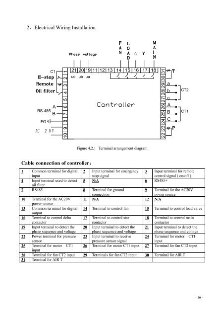
Figure 4.2.1 Terminal arrangement diagram<br />
Cable connection of controller:<br />
1 Common terminal for digital<br />
input<br />
2 Input terminal for emergency<br />
stop signal<br />
3 Input terminal for remote<br />
control signal ( on/off )<br />
4 Input terminal used to detect 5 N/A 6 RS485+<br />
oil filter<br />
7 RS485- 8 Terminal for ground<br />
connection<br />
9 Terminal for the AC20V<br />
power source<br />
10 Terminal for the AC20V 11 N/A 12 N/A<br />
power source<br />
13 Common terminal for digital 14 Terminal to control fan 15 Terminal to control load valve<br />
output<br />
16 Terminal to control delta<br />
contactor<br />
17 Terminal to control star<br />
contactor<br />
18 Terminal to control main<br />
contactor<br />
19 Input terminal to detect the<br />
phase sequence and voltage<br />
20 Input terminal to detect the<br />
phase sequence and voltage<br />
21 Input terminal to detect the<br />
phase sequence and voltage<br />
22 Power terminal for pressure 23 Input terminal to receive 24 Terminal for motor CT1<br />
sensor<br />
pressure sensor signal<br />
input<br />
25 Terminal for motor CT1 26 Terminal for motor CT1 input 27 Terminal for fan CT2 input<br />
input<br />
28 Terminal for fan CT2 input 29 Terminals for fan CT2 input 30 Terminal for AIR T<br />
31 Terminal for AIR T<br />
- 16 -