


You also want an ePaper? Increase the reach of your titles
YUMPU automatically turns print PDFs into web optimized ePapers that Google loves.
Password Enter<br />
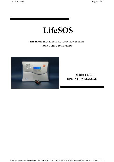
<strong>LifeSOS</strong><br />
THE HOME SECURITY & AUTOMATION SYSTEM<br />
FOR YOUR FUTURE NEEDS<br />
Model LS-30<br />
OPERATION MANUAL<br />
http://www.nettrading.ro/SCIENTECH/LS-30/MANUAL/LS-30%20manual050228.h...<br />
Page 1 of 42<br />
2009-12-18
Password Enter<br />
Table of Contents Page<br />
INTRODUCTION & INSTALLATION --------------------------------------------------------- 1<br />
BASE UNIT -------------------------------------------------------------------------------------- 3<br />
STATUS INDICATORS ------------------------------------------------------------------------ 4<br />
ELECTRICAL INSTALLATION ------------------------------------------------------------- 5<br />
MECHANICAL INSTALLATION --------------------------------------------------------- 6<br />
USER OPERATION -------------------------------------------------------------------------------- 7<br />
INITIAL STATE ------------------------------------------------------------------------------- 9<br />
(2) System Check ------------------------------------------------------------------------------ 10<br />
(2-1) Telephone Number Check ---------------------------------------------------------- 11<br />
(2-2) Voice Check -------------------------------------------------------------------------- 12<br />
(2-3) Device Check ------------------------------------------------------------------------ 12<br />
(3) Master Mode -------------------------------------------------------------------------------- 13<br />
OPERATION MODES OF LS-30 ----------------------------------------------------------- 15<br />
REACTION OF LS-30 TO DIFFERENT ALARMS ------------------------------------- 16<br />
ANSWERING THE CALL FROM LS-30 ------------------------------------------------- 17<br />
DIAL-IN CONTROL ------------------------------------------------------------------------- 18<br />
INSTALLER & CMS SETTINGS ----------------------------------------------------------------- 19<br />
(4) Installer Mode ------------------------------------------------------------------------------ 20<br />
(4-1) Set Timer --------------------------------------------------------------------------- 20<br />
(4-2) Set Telephone ---------------------------------------------------------------------- 22<br />
(4-2-1) Set Telephone Number -------------------------------------------------- 24<br />
(4-3) Set Sound --------------------------------------------------------------------------- 26<br />
(4-4) Set Device -------------------------------------------------------------------------- 28<br />
(4-4-1) Change Device Setting ------------------------------------------------- 29<br />
(4-5) Set Siren ---------------------------------------------------------------------------- 31<br />
(4-6) Set Misc. --------------------------------------------------------------------------- 32<br />
(4-7) Set GSM ---------------------------------------------------------------------------- 33<br />
(5) CMS Mode --------------------------------------------------------------------------------- 34<br />
SPECIFICATIONS--------------------------------------------------------------------------------- 35<br />
APPENDIX ------------------------------------------------------------------------------------------- 36<br />
A-1, Remote Message Display.<br />
A-2, Connection Diagram for RS-232 Computer Interface<br />
A-3, Connection Diagram for Ethernet Adaptor and Internet Remote Access<br />
A-4, Connection Diagram for X-10 Power Line Interface<br />
A-5, Terminal Board Connection<br />
A-6, Connection Diagram for GSM Module<br />
A-7, Using the Same Telephone Line to Connect LS-30, Fax Machine and Telephone Answering Machine<br />
ACCESSORIES -------------------------------------------------------------------------------------- 39<br />
Remote Controller ------------------------------------------------------------------------------ 40<br />
Magnetic Contact Transmitter ---------------------------------------------------------------- 41<br />
PIR Motion Detector --------------------------------------------------------------------------- 44<br />
Glass Break Detector -------------------------------------------------------------------------- 48<br />
Smoke Detector --------------------------------------------------------------------------------- 50<br />
Outdoor Wireless Siren With Light ----------------------------------------------------------- 52<br />
http://www.nettrading.ro/SCIENTECH/LS-30/MANUAL/LS-30%20manual050228.h...<br />
Page 2 of 42<br />
2009-12-18
Password Enter<br />
INTRODUCTION & INSTALLATION<br />
1<br />
http://www.nettrading.ro/SCIENTECH/LS-30/MANUAL/LS-30%20manual050228.h...<br />
Page 3 of 42<br />
2009-12-18
Password Enter<br />
Thank you for purchasing the LS-30 IP Based Wireless Home Security & Control System.<br />
By adopting modern microprocessor control and communication technologies, the LS-30 is designed to provide all the most advanced features that you need to<br />
protect your home and business. Moreover, you can operate the system and read its status by using the proprietary GUI (Graphic User Interface) HyperSecureLink<br />
through the Internet all over the world*. The LS-30 is not only a security system but also a home automation controller that allows you to set as many as 16<br />
programmable switches to execute daily commands throughout a whole week. With optional temperature, humidity and other sensors, the LS-30 also operates as an<br />
environmental monitoring center to report and prevent floods, gas leaks and other hazards.<br />
Although the LS-30 is a very powerful device, thanks to the interactive HMI (Human Machine Interface) programming technology, operation is simple. Just follow<br />
the instructions shown on the LCD display by answering the questions with YES/NO buttons or pressing the correct keys, and the settings are done. You can also set<br />
up the system on your laptop or PC using the optional RS-232 adapter and HyperSecureLink Software.<br />
The set up is simple, switch on back up battery, connect Base Unit to power, enroll sensors and accessories, connect the telephone line, set the telephone numbers<br />
and record the voice messages, then the LS-30 is at your service.<br />
As your security requirements grow and you become more familiar with the system, you can expand and accessorize the LS-30 to meet your specific needs. Simply<br />
call your local dealer; trained professionals can answer any questions you have regarding additional accessories.<br />
Main Features:<br />
� Security and home automation.<br />
� Computer and Internet interface.<br />
� Interactive programming with 16 x 2 LCD display.<br />
� Detailed 512 events log with time tag.<br />
� 288 sensors/ zones can be accommodated.<br />
� 16 programmable X-10 switches.<br />
� Receiving RF signal strength indication and jamming detection.<br />
� Robust multi-million RF coding and special transmission timing design avoiding interferences.<br />
� Responds to panic, burglary, fire, medical alarm and environmental hazards.<br />
� Burglar zones with supervised sensors.<br />
� Door and window open/ close detection.<br />
� Selects partial arming when at home.<br />
� Temperature, humidity and other sensors for environment monitoring.<br />
� Built-in voice dialer stores up to 10 phone numbers, 1 pager and 2 CMS data links.<br />
� Hands-free speaker-phone, two-way voice communication.<br />
� Dial-in control of listen-in, arm, disarm, event report and switch control.<br />
� Latchkey function to inform parents when kids leave or return home.<br />
� Optional GSM communication module.<br />
*For Internet connection, an optional Ethernet Adapter is needed.<br />
http://www.nettrading.ro/SCIENTECH/LS-30/MANUAL/LS-30%20manual050228.h...<br />
2<br />
Page 4 of 42<br />
2009-12-18
Password Enter<br />
t Panel Side Panel<br />
Emergency Buttons<br />
eaker<br />
To trigger the Emergency help,<br />
Board<br />
Panel<br />
Power adaptor I/P<br />
+12V/300mA<br />
BASE UNIT<br />
1. ALARM OUT SELECTOR: Set the Alarm Relay Output terminals as +12VDC output or dry contacts when the relay activates.<br />
2. Terminal Board (Refer to the APPENDIX A-5): One pair of Alarm Relay contacts, +12VDC (200mA max.) output and Ground terminal, three wire sensor inputs,<br />
two Aux. Outputs.<br />
3. COM1 (Refer to the APPENDIX A-2, A-3, A-6): Communication port for RS-232 Adaptor, Ethernet Adaptor or GSM module. (RS-232 adaptor, GSM module and<br />
Ethernet adaptor are optional).<br />
4. COM2 (Refer to the APPENDIX A-4): Communication port for X-10 Power Line Interface controller and RS-485 interface (reserved).<br />
5. AUX Audio (Refer to the APPENDIX A-6): Audio I/O for GSM module (GSM module is optional).<br />
Board & Status Display<br />
press both buttons<br />
LCD Display<br />
LED status<br />
Microphone<br />
3COM1 5 AUX Audio 4COM2<br />
1.ALARM OUT SELECTOR<br />
2. Terminal Board<br />
3<br />
Phone Set Connector<br />
Speaker Volume Control<br />
Telephone Line I/P<br />
Wire Duct<br />
Key A & AWAY<br />
Key B & HOME<br />
Key C & PAUSE<br />
Key D & ENTER<br />
Key 1 & Hands-free Telephone<br />
Key 2 & X-10 Switch Control<br />
Key 3 & Relay Control<br />
Key 4 & Door Open Control<br />
http://www.nettrading.ro/SCIENTECH/LS-30/MANUAL/LS-30%20manual050228.h...<br />
Page 5 of 42<br />
2009-12-18
Password Enter<br />
STATUS INDICATORS<br />
There are three LED indicators in green, yellow and red colors on the front panel. They represent the system operation mode and alarm/ warning status as listed in the<br />
following table.<br />
State LED Red Yellow Green<br />
DISARM OFF OFF Flash<br />
HOME OFF Flash OFF<br />
AWAY Flash OFF OFF<br />
DISARM with Warning Message OFF ON Flash<br />
DISARM with Alarm Message ON OFF Flash<br />
DISARM with Warning & Alarm<br />
Message<br />
ON ON Flash<br />
HOME with Warning Message OFF ON OFF<br />
HOME with Alarm Message ON Flash OFF<br />
HOME or AWAY with Warning<br />
& Alarm Message<br />
ON ON OFF<br />
AWAY with Warning Message Flash ON OFF<br />
AWAY with Alarm Message ON OFF OFF<br />
Note: If there are any alarm or warning messages in the event log memory, the ALARM (red LED) and WARN (yellow LED) indicators will be lighted.<br />
These indicators will be turned off after the user runs the Event Check function (Refer to (2) System Check-Event Check) or press (Hotkey)<br />
n Disarm Mode.<br />
Sensors & Zones<br />
All sensors are divided into five main categories<br />
1. 32 Controller / Panic Devices (C): Remote Controller, Keypad.<br />
2. 128 Burglary Sensors (B): Door Magnet, PIR (Passive Infrared), Glass Break Detector,<br />
Pressure Change Detector.<br />
3. 64 Fire Sensors (F): Smoke Detector, Gas Detector.<br />
4. 32 Medical Help Transmitters (M): Medical Button, Inactivity Detector.<br />
5. 32 Special Sensors (S): Flood Detector, Temperature Sensor, Humidity Sensor.<br />
All the sensors are numbered with two double digits zone number from (01-01) to (99-99), the first two-digit is Group number and the second<br />
two-digit is Unit number, set by the Installer in the initial installation.<br />
Ex.1, C 01-02: Controller number 01-02 (Group number 01, Unit number 02).<br />
Ex.2, B 02-04: Burglar Sensor number 02-04 (Group number 02, Unit number 04).<br />
Group number: User can group several sensors by using the same Group Number. For example, the sensors in the first floor are assigned as<br />
group number “01” and the sensors in the second floor are assigned as group number “02”, or you can just use group “01” for all<br />
sensors.<br />
Note: The group number ”00” is reserved for the Base Unit.<br />
4<br />
http://www.nettrading.ro/SCIENTECH/LS-30/MANUAL/LS-30%20manual050228.h...<br />
Page 6 of 42<br />
2009-12-18
Password Enter<br />
1. Switch on the internal rechargeable battery<br />
ELECTRICAL INSTALLATION<br />
Turn over the Base Unit, open the battery compartment<br />
and push the battery switch to the ON (UP) position.<br />
Note: If external power fails, the internal backup batteries can<br />
supply operational power for 6 to 15 hours, depending on the<br />
external load and the battery type in the Base Unit.<br />
Battery 2 (optional)<br />
Battery Switch Battery 1<br />
The LS-30 Base Unit can accommodate 2 rechargeable battery packs.<br />
Battery pack 1 is 9.6V/900mA(built-in) and Battery pack 2 (optional) is 9.6V/600mA, providing 6-15 hours back up time.<br />
2. Plug in the power adaptor.<br />
3. Key in Installer password. (The default Installer password is “1234”.)<br />
(Refer to the Passwords Block.)<br />
4. Enter the Installer Mode. (Refer to (4) Installer Mode)<br />
5. Program the basic settings<br />
A) Telephone numbers<br />
(Refer to (4-2) Set Telephone – (4-2-1) Set Telephone Number)<br />
B) Record voice message<br />
(Refer to (4-3) Set Sound-Record Voice)<br />
C) Enroll all the wireless devices by recording their ID codes in the Base Unit.<br />
(Refer to (4-4) Set Device-Enroll Device)<br />
6. Set other functions if necessary.<br />
7. Connect the telephone line, GSM module (If using GSM module for communication, refer to the APPENDIX A-6) or Ethernet adaptor (If internet access is<br />
needed, refer to the APPENDIX A-3).<br />
Note: For GSM module and Ethernet adaptor, please refer to their user guide.<br />
8. Install Wireless Siren and record the Base Unit’s ID code into the Wireless Siren.*<br />
* This is only needed for the user with optional Wireless Siren.<br />
(Refer to (4-5) Set Siren-Siren/Relay Test and the instructions with the Remote Siren)<br />
9. Enter into Master Mode and adjust clock. (Refer to (3) Master Mode – Set Clock)<br />
10. Test other functions, if any has been set.<br />
For details, please read the description on following pages carefully.<br />
All the above settings also can be done through the proprietary GUI program “HyperSecureLink”. Please refer to the “HyperSecureLink” user guide.<br />
http://www.nettrading.ro/SCIENTECH/LS-30/MANUAL/LS-30%20manual050228.h...<br />
5<br />
Page 7 of 42<br />
2009-12-18
Password Enter<br />
MECHANICAL INSTALLATION<br />
Placement of the Base Unit<br />
It is important for the Base Unit to have a good reception quality for the RF signals transmitted from all the sensors and controllers.<br />
� Place the Base Unit in the central area at your home or business.<br />
� Keep the Base Unit away from large appliances and other metal objects.<br />
� Locate the Base Unit near a power outlet and a telephone socket (If telephone line is needed.).<br />
Install the Door Sensors, PIR and all the other sensors according to your site planning.<br />
Check the radio signal quality from the RSSI (Receiving Signal Strength Indication) reading on the LCD by pressing the test button on the sensors. Relocate<br />
sensors/Base Unit to get the best reading (dB number) if necessary.<br />
Do not attach the transmitter on a metal surface, this will shrink the RF signal transmission range.<br />
Plug in the AC adaptor and telephone line<br />
1. Attach the<br />
Mounting Bracket<br />
2. Insert the screw<br />
Attach the Base Unit to the wall using the Mounting Bracket<br />
Mounting Bracket Tamper Switch Cam<br />
6<br />
USER OPERATION<br />
4.Tighten the screws<br />
3. Attach the Base<br />
Unit to the Mounting<br />
http://www.nettrading.ro/SCIENTECH/LS-30/MANUAL/LS-30%20manual050228.h...<br />
Page 8 of 42<br />
2009-12-18
Password Enter<br />
7<br />
http://www.nettrading.ro/SCIENTECH/LS-30/MANUAL/LS-30%20manual050228.h...<br />
5<br />
5<br />
Page 9 of 42<br />
2009-12-18
Password Enter<br />
The HMI (Human Machine Interface) of the LS-30 adopts the interactive programming technique, so that all settings and operations can be done very easily just<br />
by answering YES or NO and following the instructions on the display to enter figures.<br />
Using the HMI<br />
� If the LCD shows a question mark (?), just answer by pressing the YES or NO button.<br />
Ex: The LCD shows Master Mode? , Press YES Button you will enter into the Master Mode.<br />
� If the LCD shows the word Enter then key in proper figures followed by the Enter (D) key.<br />
Ex: The LCD shows Seconds(0-255)<br />
Enter:<br />
The system asks user to enter the figures between 0 and 255 and then press Enter (D) key.<br />
(If the user keys in 6 , 4, D, it means the timer is set at 64 seconds)<br />
� For all the Check functions, use ↑ and ↓ keys to move up and down the screen.<br />
Reading the programming flow chart<br />
State A State A-1 Down arrow<br />
Select the next state<br />
State Loop A State A-2 Sub-state Of State A-2<br />
Right arrow<br />
State A-3 Enter into the sub-state<br />
Note: Pressing FUNC/ESC at any time will let you leave the current state loop.<br />
Password<br />
As many as 14 passwords can be set in the system, each with a max. of 8 digits.<br />
Master Password (User1, default”0000”): The user with this password is authorized to manage the other user passwords and user settings.<br />
7 General User Passwords (User 2-User 8): Open to 7 general users, with any of these passwords the user can change operation modes, and check [NG1]all<br />
the system status.<br />
2 Latchkey User Password (User 9-10): User 9 and User 10 are also called Latchkey Users. The LS-30 will dial the Latchkey Number (Refer to (4-2-1)<br />
Set Telephone Number- Latchkey Number) when these users arm or disarm the system.<br />
Duress Code (User 11): Using this code to disarm the system, LS-30 will dial and send duress signal to CMS.<br />
Installer Password (default”1234”): The user with this password is authorized to enter into the Installer Mode.<br />
2 CMS Passwords (CMS1 default “1111”, CMS2 default “2222”): Open to 2 CMS stations for CMS parameter setting and system check.<br />
8<br />
http://www.nettrading.ro/SCIENTECH/LS-30/MANUAL/LS-30%20manual050228.h...<br />
Page 10 of 42<br />
2009-12-18
Password Enter<br />
In initial state, the LCD display shows DISARM & time information<br />
DISARM<br />
10:04:05 FRI<br />
INITIAL STATE<br />
After entering the password, the user can select System Check function, Hot Key Control function or enter Master, Installer and CMS modes.<br />
Initial State<br />
Master or User Password Other Password<br />
Hot Hey Enter<br />
Hot Key Process System Check or Hot Key? System Check?<br />
Yes No Yes No<br />
System Check Master Mode Installer Mode CMS Mode<br />
(2) (3) (4) (5)<br />
Hot Key: By pressing the keys in below you can enter into the specific operation mode directly.<br />
Enter AWAY Mode.<br />
Enter HOME Mode.<br />
Clear LED status, reset siren and stop dialing immediately.<br />
Enter DISARM Mode & reset siren.<br />
Enter hand free Telephone Mode. The base unit can be used as a handsfree<br />
telephone for 10 minutes when you enter this mode. Press ESC to<br />
disconnect and return to normal operation<br />
X-10 switch control (X-10 switch control module is an optional device).<br />
Close or open the alarm relay terminals on the rear panel.<br />
Open Door ( The door lock controller is an optional device).<br />
AWAY, HOME & DISARM Modes - refer to the OPERATION MODES OF LS-30.<br />
The ARM Mode in this manual means AWAY or HOME Mode.<br />
9<br />
http://www.nettrading.ro/SCIENTECH/LS-30/MANUAL/LS-30%20manual050228.h...<br />
Page 11 of 42<br />
2009-12-18
Password Enter<br />
(2) System Check Event Check Check By Sequence<br />
Check By Date<br />
Telephone Number Check (2-1)<br />
Voice Check (2-2)<br />
Device Check (2-3)<br />
Event Check: The Base Unit can store 512 event records in its memory. These events can be checked by time sequence or by entering the date information. Use ↑ and<br />
↓ keys to move up and down the screen.<br />
.<br />
Reading the Event Check Display<br />
Ex.1: LCD shows C02-03 Disarm<br />
04/26 22:08 01<br />
The controller numbered 02-03 set the system in Disarm state at 04/26 22:08;<br />
this is the latest event (Event # 01).<br />
Ex.2: LCD shows B01-02 Burglar<br />
01/02 19:32 253<br />
The Burglar sensor numbered 01-02 issued a burglar alarm at 01/02 19:32,<br />
this event is numbered as 253.<br />
10<br />
http://www.nettrading.ro/SCIENTECH/LS-30/MANUAL/LS-30%20manual050228.h...<br />
Page 12 of 42<br />
2009-12-18
Password Enter<br />
(2-1) Telephone Number Check Common 1 Number<br />
Common 2 Number<br />
Common 3 Number<br />
Common 4 Number<br />
Panic Number<br />
Burglar Number<br />
Fire Number<br />
Medical Number<br />
Special Number<br />
Latchkey Number<br />
Pager Number<br />
Pager Data<br />
Show the telephone numbers stored in the memory and their answering types. (Refer to (4-2-1) Set Telephone Number to check the usage of different telephone<br />
numbers)<br />
Reading the Telephone Number Display<br />
If the telephone number is over 16 digits, it will be divided into two parts to be shown on the<br />
screen, use ↓ key to check the lower part of the number.<br />
Common1 Common1 Common2<br />
123456789012345- Press ↓ -6789V Press ↓ 2222222222T<br />
Above example shows the Common 1 number is: 1234567890123456789 answering by Voice.<br />
The V or T following the last digit of the telephone number indicates whether the answering<br />
status is Voice or Tone. (Refer to (4-2-1) Set Telephone Number.)<br />
11<br />
http://www.nettrading.ro/SCIENTECH/LS-30/MANUAL/LS-30%20manual050228.h...<br />
Page 13 of 42<br />
2009-12-18
Password Enter<br />
http://www.nettrading.ro/SCIENTECH/LS-30/MANUAL/LS-30%20manual050228.h...<br />
Page 14 of 42<br />
2009-12-18
Password Enter<br />
(2-2) Voice Check All Voice<br />
Common Segment<br />
Panic Segment<br />
Burglar Segment<br />
Fire Segment<br />
Medical Segment<br />
Special Segment<br />
Latchkey Disarm Segment<br />
Latchkey Away Segment<br />
Playback the pre-recorded voice messages. (Refer to (4-3) Set Sound to check the usage of different segments of the voice messages)<br />
(2-3) Device Check Controller<br />
Burglar Sensor<br />
Fire Sensor Check By sequence<br />
Medical Button Check By Zone Number<br />
Special Sensor<br />
Check the current status of all the devices, using ↑ and ↓ keys to move up and down the screen.<br />
Reading the Device Status Display<br />
Ex.1 Remote Ctl. 02 The number 2 Controller is a Remote Controller, Zone number is C01-02 Normal 01-02, and status is normal.<br />
Ex.2 The number 7 Burglar sensor is a Magnetic sensor, Zone number is<br />
Mag.Sensor<br />
10-12,<br />
07<br />
10-12, with some kind of trouble. (Go to (2) System Check-Event Check to check the type of trouble the sensor is reporting.)<br />
B10-12 Trouble<br />
12<br />
http://www.nettrading.ro/SCIENTECH/LS-30/MANUAL/LS-30%20manual050228.h...<br />
Page 15 of 42<br />
2009-12-18
Password Enter<br />
(3) Master Mode Set Bell Door Bell On<br />
Door Bell Off<br />
Set Entry Delay (Refer to (4-1) Set Timer- Set Entry Delay.)<br />
Set Exit Delay (Refer to (4-1) Set Timer- Set Exit Delay.)<br />
Set Clock Time Date Day<br />
Set Switch Set House Code<br />
Set X-10 SW Auto Control<br />
Set Relay Auto. Control<br />
Set Password Master<br />
User 2<br />
User 3<br />
User 4<br />
User 5<br />
User 6<br />
User 7<br />
User 8<br />
http://www.nettrading.ro/SCIENTECH/LS-30/MANUAL/LS-30%20manual050228.h...<br />
Page 16 of 42<br />
2009-12-18
Password Enter<br />
13<br />
User 9, (Latchkey User)<br />
User10, (Latchkey User)<br />
User 11(Duress Code)<br />
http://www.nettrading.ro/SCIENTECH/LS-30/MANUAL/LS-30%20manual050228.h...<br />
Page 17 of 42<br />
2009-12-18
Password Enter<br />
Bell ON/OFF (default ON): Enable/Disable the doorbell chime.<br />
Bell ON: In Disarm Mode, the Base Unit will issue a doorbell sound (Ding! Dong!) when receiving a triggering signal from a Burglar sensor with its Bell<br />
ON/OFF status set in the ON state.<br />
Bell OFF: No doorbell chime will sound.<br />
Note: This Bell function only works for the Burglar Sensor if its Bell ON/OFF status is set<br />
in the ON state. (Refer to (4-4-1) Change Device Setting-Controller-Enable State-Bell<br />
ON/OFF)<br />
Set Switch:<br />
House Code : (default )<br />
This code should be the same as the House Code set on the X-10 switches, user can select from A to P.<br />
Set Switch Auto Control: Set the X-10 switch working schedule for home automation applications.<br />
(Please refer to the X-10 device operation instruction.)<br />
Set Relay Auto Control: Set the working schedule for the Alarm Relay.<br />
Entry Delay: Refer to Installer Mode (4-1) Entry Delay.<br />
Exit Delay: Refer to Installer Mode (4-1) Exit Delay.<br />
Latchkey User: User 9 and User 10 are also called Latchkey Users. The LS-30 will dial the Latchkey Number (Refer to (4-2-1) Set Telephone Number- Latchkey<br />
Number) when these users arm or disarm the system.<br />
Duress Code (reserved): This code is used to notify the CMS (Central Monitoring Station) that a situation has occurred that requires immediate assistance. When you<br />
key in this code in the emergency condition, the system will be disarmed but a duress signal will be sent to the CMS immediately. For a duress<br />
signal, authorities will be immediately dispatched without contacting the home or business. This function is especially useful if there is an intruder<br />
in the home or business and you do not want to alert them to the fact that you have contacted the center already.<br />
14<br />
http://www.nettrading.ro/SCIENTECH/LS-30/MANUAL/LS-30%20manual050228.h...<br />
Page 18 of 42<br />
2009-12-18
Password Enter<br />
OPERATION MODES OF LS-30<br />
The LS-30 can be set into three operation modes to fulfill your requirements in different times and situations.<br />
AWAY Mode: When you leave your home or business, set the system into Away Mode. The LS-30 will scan all the sensors that have been set on duty and issue an<br />
alarm if any sensor detects an abnormal condition after the Exit Delay passes.<br />
(Hot Key) Enter into AWAY Mode<br />
Away Mode Arming Sequence<br />
Disarm Exit Delay AWAY mode active →<br />
System status:<br />
↑ beep! (0-255 seconds)<br />
Set AWAY mode<br />
Note: When you place the LS-30 in AWAY Mode, the Base Unit will check the status of the Door Magnet sensors. If any of the sensors is still<br />
open (for example, you forget to close the back door before you leave), the Base Unit will issue a warning message and show the zone<br />
number of the sensor on the LCD display for you to check.<br />
HOME Mode: In this operation mode, those burglar sensors with their Enable State - Home Mode = Active will still be on alert and offer the protection you<br />
need while at home. (Refer to (4 4-1) Installer Mode - Set Device - Change Device Setting - Burglar Sensor - Enable State - Home Mode = Active.)<br />
(Hot Key) Enter HOME Mode<br />
DISARM Mode: The LS-30 will not issue any alarm for Burglar sensors, but 24-Hour Zone sensors (refer to (4-4-1) Change Device Setting - Burglar Sensor<br />
- 24-Hour Zone), Fire sensors, Panic and Medical Buttons still work all the time.<br />
(Hot Key) Enter DISARM MODE<br />
15<br />
http://www.nettrading.ro/SCIENTECH/LS-30/MANUAL/LS-30%20manual050228.h...<br />
Page 19 of 42<br />
2009-12-18
Password Enter<br />
REACTION OF LS-30 TO DIFFERENT ALARMS<br />
The response of the LS-30 to various alarms and abnormalities is shown below. Burglar alarms can only be issued when the system is in AWAY or HOME mode, while<br />
Fire, Panic and Medical alarms can be triggered anytime, regardless of the system operation mode. When any of these alarms occurs, the LS-30 will dial the correct<br />
phone numbers to call for help.<br />
Burglar Alarm Response<br />
AWAY Mode Entry Delay Burglar Alarm →<br />
System status:<br />
↑ (0-255 seconds) ↑<br />
Burglar sensor triggered Siren goes off, dialing---<br />
If necessary, you can interrupt dialing and stop the siren by disarming the system, and clear the<br />
alarm LED by pressing (Hot Key)<br />
Sources &<br />
Responses<br />
Alarm<br />
Burglar � PIR<br />
Press (Hot Key) : 1. Stop siren<br />
Trigger Sources Dialing Tel. Numbers<br />
Besides CMS<br />
� Door sensor<br />
� Glass Break<br />
Detector<br />
Fire � Smoke Detector<br />
� Gas Detector<br />
Panic � Panic Button of<br />
Remote Controller<br />
Pager+ Burglar+<br />
Common 1-4<br />
Sequentially<br />
Pager+ Fire+<br />
Common 1-4<br />
Sequentially<br />
Pager+ Panic+<br />
Common 1-4<br />
� Wireless Keypad Sequentially<br />
Medical � Wireless Medical Pager+ Medical+<br />
Button<br />
Common 1-4<br />
� Medical Button on<br />
Base Unit<br />
Sequentially<br />
Special � Temperature Sensor Pager+ Special+<br />
Sensor Tampered<br />
(If anti-tampering<br />
function is<br />
enabled)<br />
Sensor Trouble or<br />
Low Battery<br />
� Humidity Sensor<br />
� Flood Detector<br />
� Base Unit<br />
� PIR<br />
� Door Sensor<br />
� Glass Break<br />
Detector<br />
� Wireless Keypad<br />
� PIR<br />
� Door Sensor<br />
� Glass Break<br />
Detector<br />
� Smoke Detector<br />
� Wireless Medical<br />
Button<br />
� Special Sensor<br />
Common 1-4<br />
Sequentially<br />
2. Stop dialing,<br />
3. Clear LED status.<br />
Segments of voice<br />
message<br />
on Telephone<br />
Voice on<br />
Base Unit<br />
Siren Status<br />
Burglar+ Common Silent programmable,<br />
Fire+ Common Play Fire<br />
Message<br />
Programmable<br />
programmable,<br />
Panic+ Common Silent programmable,<br />
Medical+ Common<br />
Play Medical<br />
Message<br />
Programmable<br />
programmable,<br />
Special+ Common Silent Programmable<br />
(Disarm State)<br />
None None Silent Programmable<br />
None<br />
(Arm State)<br />
Same As Burglar Alarm<br />
None<br />
Silent<br />
http://www.nettrading.ro/SCIENTECH/LS-30/MANUAL/LS-30%20manual050228.h...<br />
OFF<br />
Page 20 of 42<br />
16<br />
2009-12-18
Password Enter<br />
ANSWERING CALLS FROM THE LS-30<br />
When you receive a call from the LS-30, you can follow the procedures below to communicate with the system.<br />
� When you pick up the phone, your voice on the line [NG2]will trigger the appropriate message from the LS-30.<br />
� You will hear the prerecorded message twice, telling you what event the system is reporting.<br />
� After the announcement, the LS-30 enters the monitoring mode for 60 seconds. You can hear any sound picked up by the microphone on the Base Unit or talk with<br />
the people in house.<br />
� During the 60 seconds, you can also control your LS-30 through the telephone keypad.<br />
Press 0 : LS-30 disconnects immediately.<br />
Stop any further dialing.<br />
Stop siren.<br />
Press 1 : LS-30 disconnects immediately.<br />
LS-30 dials the next number.<br />
Press 5 : Enable 2-way communication.<br />
Press any other key: LS-30 will extend the connection for another 60 seconds.<br />
The sound of the siren or noise from the environment may interrupt the decoding of the input<br />
key tone, so keep pressing the key until the command becomes effective.<br />
� If this telephone number needs a DTMF tone acknowledgment, remember to press a key on the telephone keypad in the answering process to prevent LS-30 from<br />
redialing this number later.<br />
Answering Sequence<br />
LS-30 Voice Monitoring &<br />
Dialing Announcement Communication<br />
Twice 60 seconds<br />
Ring!---Ring!<br />
Answered by voice (“hello”)<br />
or press a DTMF key<br />
0 : LS-30 disconnects, stop further dialing & stop siren<br />
1 : LS-30 disconnects and dial next number<br />
5 : Enable 2-way communication<br />
: Any other DTMF key pressed, extend connection for<br />
another 60 seconds.<br />
17<br />
http://www.nettrading.ro/SCIENTECH/LS-30/MANUAL/LS-30%20manual050228.h...<br />
Page 21 of 42<br />
2009-12-18
Password Enter<br />
DIAL-IN CONTROL<br />
You can control and check with your LS-30 from a phone anywhere in the world by enabling the auto-answer function (refer to (4-2) Set Telephone – Set Auto<br />
Answer) and set the ring count number.<br />
Notes: 1. If you connect a fax machine or auto-answering machine on the same telephone line, you might need refer to it’s manuals and Appendix A-7 to avoid any<br />
misoperation.<br />
2. The ring count number should be over three; otherwise, the noise on telephone line may trigger the dial-in control sequence.<br />
3. Any phone set with pulse dialing will not connect with or control the system.<br />
The operation of dial-in control is as follows:<br />
1. Dial the telephone number to which LS-30 is connected.<br />
2. After the preset ring count number, you will hear beeps.<br />
3. Key in the password (preceded by * and followed by # ) from the telephone keypad within 30 seconds. If the password is correct, you will hear beeps again,<br />
otherwise you should enter the password again.<br />
4. After entering the valid password, the LS-30 will enter monitoring mode for 60 seconds. During this time, you can enter commands from the telephone<br />
keypad to control the LS-30.<br />
* 0 : Disarm the LS-30 (echoed by beeps) after you exit Dial-in Control.<br />
* 1 : Arm the LS-30 in Home Mode (echoed by beeps) after you exit Dial-in Control.<br />
* 2 : Arm the LS-30 in Away Mode (echoed by beeps) after you exit Dial-in Control.<br />
* 4 : Check alarm event, hear voice message, or beeps if no alarm event.<br />
* 5 : 2-way speakerphone/monitoring only (echoed by beeps).<br />
* 6 x x 1 : Turn on the switch number x x (01-16).<br />
* 6 x x 0 : Turn off the switch number x x (01-16).<br />
* 7 1 : Turn on the Relay.<br />
* 7 0 : Turn off the Relay.<br />
* 9 : Disconnect the line immediately.<br />
Any other keys will extend the monitoring period for another 60 seconds (echoed by beeps).<br />
The Process of Dial-in Control<br />
Dial Phone Number Enter Password<br />
in 30 seconds 60 sec. monitoring<br />
Ring count as user set *xx--xx# Ready for key tone command<br />
18<br />
INSTALLER & CMS SETTINGS<br />
http://www.nettrading.ro/SCIENTECH/LS-30/MANUAL/LS-30%20manual050228.h...<br />
Page 22 of 42<br />
2009-12-18
Password Enter<br />
19<br />
http://www.nettrading.ro/SCIENTECH/LS-30/MANUAL/LS-30%20manual050228.h...<br />
Page 23 of 42<br />
2009-12-18
Password Enter<br />
The Installer Mode is for the installer to set up the system.<br />
Enter Installer Password<br />
(4) Installer Mode Set Timer (4-1)<br />
(4-1) Set Timer Set Entry Delay<br />
Set Telephone (4-2)<br />
Set Sound (4-3)<br />
Set Device (4-4)<br />
Set Siren (4-5)<br />
Set Misc. (4-6)<br />
Set GSM (4-7)<br />
Set Exit Delay<br />
Set Inner Siren Time<br />
Set Relay Action Time<br />
Set Sensor Supervise Time Unit In Second<br />
Set Remote Siren Time Unit In Minute<br />
20<br />
http://www.nettrading.ro/SCIENTECH/LS-30/MANUAL/LS-30%20manual050228.h...<br />
Page 24 of 42<br />
2009-12-18
Password Enter<br />
Entry Delay: (0-255 seconds, default 0 sec.)<br />
This setting is the time between any burglar alarm triggers and when the alarm reaction procedure starts.<br />
When you return home and open the door, the Base Unit will issue warning beeps (if the Entry Delay Beep = On) to remind you that the system is still in the Arm<br />
state and you should disarm the system within this time. (Refer to the (4-3) Set Sound - Entry Delay Beep.)<br />
AWAY Mode Entry Delay Burglar Alarm →<br />
System status:<br />
↑ (0-255 seconds) ↑<br />
Burglar sensor triggered Siren goes off, dialing---<br />
This Delay only works on the Controller with its Delay ON/OFF setting in ON state.<br />
(Refer to (4-4-1) Change Device Setting - Burglar Sensor - Enable State - Delay ON/OFF.)<br />
Exit Delay: (0-255 seconds, default 0 sec.)<br />
This setting is the time between selecting the AWAY mode and when the AWAY arm becomes effective. During this time, the Base Unit will issue<br />
warning beeps to remind the people still in the house to leave as soon as possible.<br />
Disarm Exit Delay AWAY arm effective →<br />
System status:<br />
↑ beep! (0-255 seconds)<br />
Set AWAY mode<br />
This Delay only works on the Controller with its Delay ON/OFF setting in ON state.<br />
(Refer to (4-4-1) Change Device Setting-Controller-Enable State-Delay ON/OFF)<br />
Inner Siren Time: 0-255 seconds (default 60 sec.)<br />
The length of time the Inner Siren sounds when the alarm trips.<br />
Relay Action Time: 0 second to 120 minutes (default 60 sec.)<br />
The activation time of the Alarm Relay output (on the rear panel) when the alarm trips.<br />
Sensor Supervise Time: 0-24 Hours (default 4 Hours)<br />
The LS-30 is a supervised RF wireless system, meaning all the Burglar sensors send “heartbeat” RF signals to the Base Unit at a certain time interval. If<br />
the Base Unit does not receive the RF check signal from a certain sensor within the Sensor Supervise time, the LS-30 will consider this sensor to be<br />
missing and issue a warning message.<br />
This time can be set from 0 to 24 hours (0 hour means system will not check for the “heartbeat” signal).<br />
Remote Siren Time: 0 seconds to 30 minutes (default 60 sec.)<br />
The length of time the external wireless Remote Siren sounds when the alarm trips. (The Remote Siren is an Option.)<br />
21<br />
http://www.nettrading.ro/SCIENTECH/LS-30/MANUAL/LS-30%20manual050228.h...<br />
Page 25 of 42<br />
2009-12-18
Password Enter<br />
(4-2) Set Telephone Set Telephone Number (4-2-1)<br />
Set Dial Mode Tone<br />
Pulse 33/66<br />
Pulse 40/60<br />
Set Auto Answer Auto Answer On Set Ring Count<br />
Auto Answer Off<br />
Set Telephone Line Cut Detection Permanent Off<br />
Away Mode On<br />
Permanent On<br />
Set Cease Dialing Mode 30 Minutes Due<br />
CMS Report OK<br />
Set Tel. Ringer Tel. Ringer On<br />
Tel. Ringer Off<br />
Set Dial Tone Check Dial Tone Check Enable<br />
Set Tel/GSM Link<br />
Dial Tone Check Disable<br />
Page 26 of 42<br />
Dial Mode: Tone/ Pulse 33/66 / Pulse 40/60 (default, Tone)<br />
Check your telephone system and select the proper Pulse or Tone mode for the auto-dialer.<br />
Auto Answer Ring Count: Auto Answer ON Ring Count 1-30/ Auto Answer OFF (default, Auto Answer OFF)<br />
Auto-Answer ON: The Base Unit will answer the incoming call automatically after the ring count number set in this command has been reached. (You have<br />
http://www.nettrading.ro/SCIENTECH/LS-30/MANUAL/LS-30%20manual050228.h...<br />
2009-12-18
Password Enter<br />
to switch on this function, if you want to use dial-in control. Three or more ring counts are recommended to avoid triggering by noise.)<br />
Auto Answer OFF: The Base Unit will not answer the incoming call.<br />
Telephone Line Cut Detection: Permanent OFF/ Away Mode ON/ Permanent ON (default, Permanent OFF)<br />
The LS-30 can check the telephone line voltage and if the line is cut, the siren will go off (the Inner Siren should be switched on) to alert the user. (Refer to<br />
(4-5) Set Siren - Inner Siren.)<br />
.<br />
Permanent OFF: Never check the telephone line state.<br />
Away Mode ON: Check the telephone line state only in AWAY mode.<br />
Permanent ON: Always check the telephone line state.<br />
Cease Dialing Mode: 30 Minutes / CMS Report OK (default, 30 Minutes)<br />
30 Minutes: The auto-dialer stops dialing after 30 minutes or all the telephone numbers have been dialed 10 times without a successful connection.<br />
CMS Report OK: The auto-dialer stops dialing after the report to CMS is successful.<br />
Tel. Ring: ON/OFF (default, OFF)<br />
Tel. Ring ON: Sound the ringer for incoming calls.<br />
Tel. Ring OFF: Ringer deactivated for incoming calls.<br />
Dial Tone Check: Enable/Disable (default, Enable)<br />
Dial Tone Check Enable: The auto-dialer checks for a dial tone before dialing.<br />
Dial Tone Check Disable: The auto-dialer will not check for a dial tone and dials immediately.<br />
Tel/GSM Link: (default, Tel.)<br />
Tel. Link: Dial out the alarm report from telephone line.<br />
GSM Link: Dial out the alarm report from GSM module.<br />
If GSM link is used, refer to (4-7) Set GSM to set all the parameters needed for GSM communication and APPENDIX A-6 for GSM link set up.<br />
23<br />
22<br />
http://www.nettrading.ro/SCIENTECH/LS-30/MANUAL/LS-30%20manual050228.h...<br />
Page 27 of 42<br />
2009-12-18
Password Enter<br />
(4-2-1) Set Telephone Number Common 1 Number<br />
Common 2 Number<br />
Common 3 Number<br />
Common 4 Number<br />
Panic Number Answer By Voice<br />
Burglar Number Answer By Tone<br />
Fire Number<br />
Medical Number<br />
Special Number<br />
Latchkey Number<br />
Pager Number<br />
Pager Data<br />
As many as to 10 telephone numbers and one pager number can be set in the auto-dialer, each up to 23 digits.<br />
4 common numbers and pager number:<br />
These will be dialed in all types of alarm. They can be the numbers of your office, friends, neighbors or family members.<br />
5 specific numbers each for different alarms:<br />
These will be dialed only when the LS-30 is triggered by the specified alarm. For example, the fire number will be dialed only in a fire alarm.<br />
Latchkey number:<br />
This number will be dialed only if the Latchkey Remote Controller (Refer to (4-4-1) Change Device Setting- Enable State- Latchkey) or the user with the<br />
Latchkey password (User 9 and User 10 password) disarm the system or set the system in AWAY mode.<br />
This function is useful to parents who want to make sure their children have returned home safely. Usually, the Latchkey number will be the parents’ mobile<br />
phone number.<br />
24<br />
Pause Insertion<br />
http://www.nettrading.ro/SCIENTECH/LS-30/MANUAL/LS-30%20manual050228.h...<br />
Page 28 of 42<br />
2009-12-18
Password Enter<br />
Note: Use Pause key to insert pauses between telephone number digits for dialing<br />
to a PABX extension number. Each pause is equivalent to a 3-second break.<br />
Answering status: Voice/ Tone (default, Voice).<br />
After dialing, the LS-30 needs an acknowledgement from the called party, either by voice like “Hello” or by a DTMF key tone to ensure the call is<br />
connected successfully. With no acknowledgement, the call will be deemed to have failed and will be redialed in the next loop.<br />
Dialing Sequence for Alarm Report<br />
CMS1→CMS2→SMS1→SMS2→Pager→Specific alarm number→1’st to 4’th Common numbers.<br />
If there is any number that cannot be connected successfully, the auto-dialer will skip to the next one and try again in the next loop until all the<br />
numbers have been tried 10 times or the cease dialing condition has been reached. (Refer to (4-2) Set Telephone - Set Cease Dialing Mode.)<br />
Note: CMS1 and CMS2 are Central Monitoring Station numbers (Refer to the (5) CMS Mode).<br />
SMS1 and SMS2 are mobile phone Short Message Service and only valid for the system with GSM module.<br />
25<br />
http://www.nettrading.ro/SCIENTECH/LS-30/MANUAL/LS-30%20manual050228.h...<br />
Page 29 of 42<br />
2009-12-18
Password Enter<br />
(4-3) Set Sound Record Voice Common Segment 13 Second Record<br />
Panic Segment 4 Second Record<br />
Burglar Segment 4 Second Record<br />
Fire Segment 4 Second Record<br />
Medical Segment 4 Second Record<br />
Special Segment 4 Second Record<br />
Latchkey Disarm 4 Second Record<br />
Latchkey Away 4 Second Record<br />
Voice Check (Same as 2-2)<br />
Set Entry Delay Beep Delay Beep On<br />
Delay Beep Off<br />
Record Voice: After an alarm call connects successfully, the LS-30 will play the prerecorded voice message that corresponds to the alarm type.<br />
The messages should be recorded in their specified segments.<br />
Common Segment (13 seconds): The voice to be played during all alarm types. This segment should contain your name, address and telephone number.<br />
Ex: “This is ---, I live at---, phone number is---.”<br />
Panic Segment (4 seconds): The voice to be played during Panic alarm.<br />
Ex: “Break-in! Break-in! Calling for emergency help.”<br />
Burglar Segment (4 seconds): The voice to be played during Burglar alarm.<br />
Ex: “Burglar! Burglar! Calling for emergency help.”<br />
Fire Segment (4 seconds): The voice to be played during Fire alarm.<br />
Ex: “Fire! Fire! Calling for emergency help.”<br />
Medical Segment (4 seconds): The voice to be played during Medical alarm.<br />
Ex: “Heart patient! Calling for emergency help.”<br />
Special Segment (4 seconds): The voice to be played during Special alarm.<br />
Ex: “High temperature in the building! Calling for an alert.”<br />
Latchkey Disarm (4 seconds): The voice to be played when a latchkey user disarm the system.<br />
Ex: “I’m home.”<br />
26<br />
http://www.nettrading.ro/SCIENTECH/LS-30/MANUAL/LS-30%20manual050228.h...<br />
Page 30 of 42<br />
2009-12-18
Password Enter<br />
Latchkey Away (4 seconds): The voice to be played when a latchkey user set the system in AWAY mode.<br />
Ex: “I’m out.”<br />
Entry Delay Beep: ON/OFF (default, OFF )<br />
Entry Delay Beep ON: The Base Unit will generate beeps in the Entry Delay interval and the beeping speed will get faster until the end of the delay time. (Refer to<br />
(4-1) Set Timer-Entry Delay)<br />
Entry Delay Beep OFF: No beeps in the Entry Delay interval.<br />
27<br />
http://www.nettrading.ro/SCIENTECH/LS-30/MANUAL/LS-30%20manual050228.h...<br />
Page 31 of 42<br />
2009-12-18
Password Enter<br />
4-4) Set Device Enroll Device Controller Enroll<br />
Burglar Sensor Enroll<br />
Fire Sensor Enroll Zone Number<br />
Medical Button Enroll<br />
Special Sensor Enroll<br />
Change Device Setting (4.4.1)<br />
Delete Device Controller Delete<br />
Burglar Sensor Delete<br />
Fire Sensor Delete Zone Number<br />
Medical Button Delete<br />
Special Sensor Delete<br />
Special Sensor Limit Set Enter Zone Number High Limit<br />
Wire Sensor Assignment Select Input Low Limit<br />
Select Type (4.4.1) Enable State<br />
Enroll Device: The LS-30 uses smart code technology. The Base Unit identifies its sensors by their unique IDs, so the Base Unit has to learn all the sensors’ ID codes<br />
in the initial system setup. (Each sensor has a unique ID that is preset in the factory.)<br />
60 seconds for Device Enroll<br />
After initiating the Enroll Device procedure, there is a 60-second time window for the device to transmit an RF signal to complete the code<br />
learning.<br />
Delete Device: Remove device from the system.<br />
Special Sensor Limit Set: Set High/Low trigger limits for sensors like temperature sensor and<br />
humidity sensor.<br />
Wire Sensor Assignment: Set the parameters for the wire sensor inputs from the rear panel.<br />
Up to three wire sensors can be assigned.<br />
(The wire sensor input can select close or open trigger.<br />
The Zone numbers of the wire sensors are fixed to “00-01”, “00-02” and “00-03”.)<br />
28<br />
http://www.nettrading.ro/SCIENTECH/LS-30/MANUAL/LS-30%20manual050228.h...<br />
Page 32 of 42<br />
2009-12-18
Password Enter<br />
(4-4-1) Change Device Setting Controller Change<br />
Burglar Sensor Change Enter Zone Number<br />
Fire Sensor Change Enable State<br />
Medical Button Change Zone Number<br />
Special Sensor Change Switch Control<br />
Enable state of devices:<br />
Device On Duty/Bypass (default On Duty): (For all devices)<br />
Device On Duty: This sensor is working in the system currently.<br />
Device Bypass: Bypass this sensor; the system will ignore the alarm signal received from this sensor.<br />
Delay ON/OFF (default OFF): (For Controller & Burglar sensor)<br />
Delay ON: (Refer to (4-1) Set Timer - Exit Delay/Entry Delay.)<br />
For the Remote Controller, the Exit Delay will be imposed on the Away command from this controller.<br />
For the Burglar sensor, the Entry Delay will be imposed on the Burglar alarm signal from this sensor.<br />
Delay OFF: The trigger signal or command from this sensor or controller will be processed immediately regardless of the Exit/Entry Delay setting in (4-1).<br />
Voice Warn ON/OFF (default Voice Warn ON): (For Fire sensor & Medical Button)<br />
Voice Warn ON: If this sensor sends an alarm signal, there will be a 30-second voice warning from the Base Unit before the alarm reaction procedure starts.<br />
Voice Warn OFF: There is no voice warning. The Base Unit responds immediately when there is an alarm issued by this device.<br />
Siren/Relay ON/OFF (default Siren/Relay ON, only OFF for Controller): (For all devices)<br />
Siren/Relay ON: The Relay will act and sirens (Both Inner Siren and Remote Siren) will go off when there is an alarm issued by this sensor after the Delay<br />
time or Voice Warning passes.<br />
Siren/Relay OFF: The Relay will not act and sirens will keep silent when there is an alarm issued by this device.<br />
Latchkey ON/OFF (default Latchkey OFF): (For Remote Controller)<br />
Latchkey ON: This Remote Controller is assigned as a Latchkey Remote Controller. (Refer to (4-2-1) Set Telephone Number - Latchkey Number.)<br />
Latchkey OFF: No latchkey number will be dialed for this controller.<br />
29<br />
http://www.nettrading.ro/SCIENTECH/LS-30/MANUAL/LS-30%20manual050228.h...<br />
Page 33 of 42<br />
2009-12-18
Password Enter<br />
24-Hour Zone YES/NO (default 24-Hour Zone NO): (For Burglar sensor)<br />
24-Hour Zone/YES: This Burglar sensor’s alarm signal will be processed all the time regardless of the system operation mode, either in Arm<br />
or Disarm.<br />
24-Hour Zone/NO: This sensor’s alarm signal will only be processed in Arm Mode.<br />
Home Mode Active/Inactive (PIR default Inactive, Magnet default Active): (For Burglar sensor)<br />
Home Mode Active: This Burglar sensor will trigger alarm in Home Mode operation.<br />
Home Mode Inactive: This Burglar sensor will not trigger alarm in Home Mode operation, only trigger in Away Mode operation.<br />
Bell ON/OFF (default Bell OFF): (For Burglar sensor)<br />
Bell ON: In Disarm Mode, the Base Unit will issue a doorbell chime when receiving a trigger signal from this sensor if the Bell status is set ON in Master<br />
Mode (Refer to (3) Master Mode - Bell Check - Door Bell.)<br />
Bell OFF: In Disarm Mode, doorbell chime will not sound when receiving a trigger signal from this sensor.<br />
Suggestion: This state should be switched on for the Door Magnet sensors on the front and back doors.<br />
Supervision ON/OFF: (Automatically set by the sensor itself)<br />
(Refer to (4-1) Set Timer - Sensor Supervise Time.)<br />
Supervision ON: System will check the “heartbeat” signal from this sensor.<br />
Supervision OFF: System will not check the “heartbeat” signal from this sensor.<br />
RF Voice ON/OFF: (Automatically set by the sensor itself)<br />
2-way Radio ON/OFF: (Automatically set by the sensor itself)<br />
Switch control: Select the switches that will be activated when this sensor is triggered.<br />
X-10 Switch<br />
As many as 16 X-10 switches (optional devices) can be controlled by each system. For setting on the X-10 devices, refer to the instructions with the<br />
X-10 switch.<br />
Note: For Remote Controller, if you press the DISARM button in DISARM Mode, the switches those have been assigned as active switches will<br />
be turned ON or OFF.<br />
30<br />
http://www.nettrading.ro/SCIENTECH/LS-30/MANUAL/LS-30%20manual050228.h...<br />
Page 34 of 42<br />
2009-12-18
Password Enter<br />
(4-5) Set Siren Set Inner Siren Inner Siren On<br />
Inner Siren Off<br />
Set Mode Change Chirp Mode Chirp On<br />
Mode Chirp Off<br />
Set Tamper Siren In Disarm Siren On<br />
Siren Off<br />
Set Remote Siren Type Standard Series<br />
HA Series ID Number Change<br />
Siren/Relay Test Start Test<br />
Inner Siren: ON/OFF (default ON)<br />
This is the control switch of the built-in siren.<br />
Inner Siren On: Enabling the Inner Siren.<br />
Inner Siren Off: Switch off the Inner Siren. (The Siren always keeps silent.)<br />
The conditions for the Inner Siren to go off when alarm trips:<br />
1. The Inner Siren is enabled.<br />
2. The Siren ON/OFF state of the sensor triggering the alarm is in the ON state. (Refer to (4-4-1) Change Device Setting-Siren/Relay ON/OFF).<br />
3. The Inner Siren Time has been set. (Refer to (4-1) Set Timer-Inner Siren Time)<br />
Mode Change Chirp: ON/OFF (default OFF)<br />
Mode Change Chirp On: The Sirens will sound for about 0.3 second (Inner Siren has been enabled) when the Operation Mode changes. (Away /<br />
Disarm).<br />
Mode Change Chirp Off: The Sirens will keep silent when the operation Mode changes.<br />
Tamper Siren In Disarm: ON/OFF (default OFF)<br />
Tamper Switch<br />
There is a Tamper Switch in the Base Unit (Please refer to Attach the Base Unit to the wall using the Mounting Bracket). This switch will be<br />
closed by the Tamper Switch Cam when the Base Unit is attached to the Mounting Bracket. If someone detaches the Base Unit from the Mounting<br />
Bracket, the Tamper Switch will be triggered.<br />
Also refer to the specific sensors descriptions for more about their tamper function.<br />
31<br />
Page 35 of 42<br />
Tamper Siren In Disarm On: The Siren will go off (Inner Siren has been enabled) if some one<br />
detaches the Base Unit from the Mounting Bracket or triggers the Tamper Switch (on Base Unit or sensors) in Disarm Mode.<br />
Tamper Siren In Disarm Off: The siren will not go off when receiving the tamper signal from sensors or from the Base Unit in Disarm Mode.<br />
Set Remote Siren Type: Select the type of the remote siren used in the system. (reserved)<br />
Siren/Relay Test: This test will activate the Inner Siren, close the Relay contacts and send an Activate signal to the Remote Siren (if remote siren installed)<br />
immediately regardless of the Inner Siren state.<br />
http://www.nettrading.ro/SCIENTECH/LS-30/MANUAL/LS-30%20manual050228.h...<br />
2009-12-18
Password Enter<br />
(4-6) Set Misc. Set RF Jamming Warning<br />
Check ROM Version<br />
Reset To Factory Default Enter to Reconfirm<br />
Emergency Button Assignment<br />
Set Inactivity<br />
Set Password<br />
Set RS-232 Control<br />
RF Jamming Warning: (default OFF)<br />
Enable or disable the RF jamming warning.<br />
Reset To Factory Default:<br />
All the settings in the Base Unit will be returned to factory default.<br />
Emergency Button Assignment: Panic / Medical (default Panic)<br />
Select the function of the Emergency Button as a Panic Button or a Medical Button.<br />
Set Inactivity: ON/ OFF (default OFF)<br />
Inactivity On: Treats the Inactivity signal from the Wireless Medical Button as a medical help signal.<br />
Inactivity Off: Ignore the Inactivity signal from the Wireless Medical Button.<br />
Set Password: (default “1234”) Edit the Installer Password.<br />
Set RS-232 Control: (default Enable)<br />
Control Enable: The RS-232 interface is open for user to access the system.<br />
Control Disable: The RS-232 interface is closed.<br />
32<br />
http://www.nettrading.ro/SCIENTECH/LS-30/MANUAL/LS-30%20manual050228.h...<br />
Page 36 of 42<br />
2009-12-18
Password Enter<br />
(4-7) Set GSM Display RSSI<br />
Set GSM Number SMS Number 1(Mobile phone number)<br />
SMS Number 2 (Mobile phone number)<br />
GSM Number<br />
GSM PIN<br />
This setting is only valid for the system with GSM Module and the Tel/GSM Link is set as Link=GSM. (Refer to (4-2) Set Telephone- Set Tel/GSM Link).<br />
Display RSSI (Received Signal Strength Indication): To show the GSM signal strength where the GSM module locates. Try to find a place where the signal reading<br />
is the best.<br />
(The reading is in negative number. For example –50dBm is greater than –60dBm)<br />
SMS Numbers: These two mobile phone numbers will receive the SMS alarm message from the system if any alarm has been tripped.<br />
GSM Number: This is the telephone number of the SIM card of the GSM module. (When you buy the service from your GSM system provider, you will receive a SIM<br />
card with the telephone number. This SIM card has to be inserted into the SIM card holder on the GSM module.)<br />
PIN Number: The PIN number of the SIM card. (If you want to change the PIN number, please insert the SIM card to a mobile phone and use this mobile phone to<br />
change the PIN number. The GSM module can’t change the PIN number.)<br />
SMS Alarm Message<br />
The system will send SMS message to the SMS Number that has been set in the system with<br />
alarm type, zone number, time, date and GSM Number.<br />
Ex. Burglar 01-03 11:30 12/01/04 0933123456.<br />
Note: The strong RF signal (max. 2W) from the GSM module may induce some noise to the audio circuit of the Base Unit. After you find a place for the GSM<br />
module, make a test call from the Base Unit and listen to the audio carefully. If you can hear the humming noise, please move the GSM module and the<br />
antenna to a better place with minimum noise. In general, move the GSM module and the antenna away from the Base Unit will be a solution.<br />
(5) CMS Mode Set CMS1<br />
Set CMS2<br />
Set Mode Change Report Report On<br />
Report Off<br />
Auto Link Check Auto Link Check On Check Interval<br />
33<br />
Auto Link Check Off<br />
http://www.nettrading.ro/SCIENTECH/LS-30/MANUAL/LS-30%20manual050228.h...<br />
Page 37 of 42<br />
2009-12-18
Password Enter<br />
Loopback Test Start Test<br />
Set Telephone Number Telephone Number<br />
Set Password<br />
Account Number<br />
Mode Change Report: ON/ OFF (default OFF)<br />
Mode Change Report On: The LS-30 will report to the CMS if the operation mode (Away/Home/Disarm) has been changed.<br />
Mode Change Report Off: The LS-30 will report to the CMS with only alarm and warning events but no operation mode report.<br />
Auto Link Check: ON/OFF (default OFF)<br />
Auto Link Check On: The LS-30 will send a check signal to the CMS periodically according to the Interval setting.<br />
Auto Link Check Off: Disable the Auto Link Check function with the CMS.<br />
Loopback Test: The LS-30 will send a check signal to the CMS immediately.<br />
CMS Telephone numbers and account number:<br />
The CMS telephone number (16 digits Max.) and the user account number (8 digits Max.) are used to link to the CMS station.<br />
34<br />
http://www.nettrading.ro/SCIENTECH/LS-30/MANUAL/LS-30%20manual050228.h...<br />
Page 38 of 42<br />
2009-12-18
Password Enter<br />
Base Unit<br />
SPECIFICATIONS<br />
Input Power: 12VDC/300mA.<br />
Standby Current: 60-90mA. (depending on the receiver type and rechargeable battery)<br />
RF : (Follow local regulations, other frequencies as requested)<br />
Frequency: 426, 433 and 868MHz<br />
Data Modulation: Narrow-band FM or OOK.<br />
Power: less than 10mW.<br />
Range: about 200ft or more @open field, 25℃.<br />
Receiver Type: super heterodyne.<br />
RF Security Code: 16,777,216 combinations with check sum for each type of sensors.<br />
More than 4 billion combinations in total.<br />
Dialing Type: Pulse/Tone selectable.<br />
Preset Telephone Number: 10 phone numbers, one pager, 2 CMS data links.<br />
Voice Recording: 120 seconds in total.<br />
Emergency announcement in 6 segments, 13 seconds for common segment, 4 seconds each for Panic, Burglar, Fire, Medical and Special segment.<br />
Event Log: max. 512 records.<br />
Display: 3 LEDs, 2x16 LCD panel in blue color with backlight.<br />
Sensor Zones: Total 288 zones. (Burglar zones x 128, Fire zones x 64, Controller zones x 32,<br />
Medical zones x 32, Special sensor zones x 32)<br />
Wire Sensor Input: total 3 sensors.<br />
Memory Back-up Time: min. 3 months after power break.<br />
Battery Back Up Operation Time: About 6-15 hours. (depending on back up battery type, only for the Base Unit)<br />
Password: 14 passwords each with max. 8 digits.<br />
Alarm Out: 230V AC/ 3A rate relay contacts or 12V DC/200mA output.<br />
Delay Activation Time: 0- 255 seconds programmable.<br />
Switch Control Interface: 16 units of X-10 switch.<br />
Digital Interfaces: RS-232 (9600/ 8 bits/ no parity/ 1 stop bit) or 10M/100M Ethernet (optional),<br />
RS-485 (reserved).<br />
Remote Display Memory: 32 characters/ set, total 10 sets.<br />
Internal Siren: 110dB at 30cm distance.<br />
CMS protocol: Contact ID.<br />
Clock Accuracy: within 5 seconds daily.<br />
Telephone Line Cut Detection Voltage: 20V+/- 4V. (This function may not be used in some country.)<br />
Operation Temp.: -10℃~40℃.<br />
Storage Temp.: -20℃~55℃.<br />
Humidity:10-95%RH.<br />
Size: 248x180x52 mm.<br />
Weight: about 950 g.<br />
(The manufacturer reserves the rights to change the specifications without prior notice)<br />
A-1. Remote Message Display.<br />
35<br />
APPENDIX<br />
The user or CMS can send 32-character message to the LS-30 if the Base Unit has been connected to the Internet through the Ethernet Adaptor (optional) by using the<br />
perSecureLink program.<br />
The LCD display will show “Messages Come In” and issue a warning sound periodically to remind the user if any new message has been received by the LS-30 Base<br />
t. The user can check the message by pressing (Hot Key) 5 after the password has been entered in Disarm Mode.<br />
Up to 10 messages with time tag can be stored in the memory of the Base Unit. Stop the reminder message and warning sound by pressing (Hot Key) C after entering<br />
password.<br />
(Note: ! and & are not allowed in the message)<br />
A-2. Connection Diagram for RS-232 Computer Interface<br />
http://www.nettrading.ro/SCIENTECH/LS-30/MANUAL/LS-30%20manual050228.h...<br />
Page 39 of 42<br />
2009-12-18
Password Enter<br />
To LS-30<br />
COM1<br />
COM1 cable RS-232 Adaptor HyperSecureLink Software<br />
e: If a series COM port is not available on your PC, you can use an USB to COM Port Adaptor to connect to your computer.<br />
A-3. Connection Diagram for Ethernet Adaptor and Internet Remote Access<br />
To LS-30<br />
COM1<br />
COM1 Cable Ethernet Adaptor Router<br />
A-4. Connection Diagram for X-10 Power Line Interface<br />
Power Line<br />
X-10 Appliance Module X-10 power Line Interface Controller X-10 Cable<br />
36<br />
To PC<br />
COM Port<br />
Internet<br />
To LS-30<br />
HyperSecureLink or<br />
CMS polling software<br />
http://www.nettrading.ro/SCIENTECH/LS-30/MANUAL/LS-30%20manual050228.h...<br />
Page 40 of 42<br />
2009-12-18
Password Enter<br />
A-5. Terminal Board Connection<br />
_<br />
+<br />
Wire Siren<br />
+12V DC: This terminal provides +12V/200mA output for customer to connect their own devices.<br />
(Note: This output will be shut down if the external power fails.)<br />
ALARM OUT: These two terminals are the Alarm Relay Outputs. These two terminals can be selected as dry contact or +12V/GND output, depend on the setting of<br />
the ALARM OUT SELECTOR.<br />
SENSOR INPUT: There are three terminals, AUX 1 (Wire Sensor 1), AUX 2 (Wire Sensor 2) and SENSOR IN (Wire Sensor 3), can accept NO/NC type alarm<br />
sensor input. Please refer to (4-4) Set Device-Wire Sensor Assignment for the setting of these three sensor inputs.<br />
AUX OUT 2: This output represents the status of system operation mode. In the ARM mode (AWAY & HOME) this output will send out +5V voltage (protected by<br />
a serial 2k ohms resistor) to this terminal. User can connect a LED display for ARM state indication purpose.<br />
A-6. Connection Diagram for GSM Module<br />
(Only available for the PCB version after LS30-02A)<br />
GSM Antenna GSM Module<br />
Wire<br />
Sensor 3<br />
COM1 Cable<br />
To COM1<br />
(When you receive the GSM module, you have to open the case and insert the SIM card first before operation.)<br />
37<br />
Arm LED<br />
Indicator<br />
Wire<br />
Sensor 2<br />
To AUX Audio<br />
Audio Cable<br />
http://www.nettrading.ro/SCIENTECH/LS-30/MANUAL/LS-30%20manual050228.h...<br />
Wire<br />
Sensor 1<br />
Page 41 of 42<br />
2009-12-18
Password Enter<br />
Using the Same Telephone Line to Connect LS-30, Fax Machine and Telephone Answering<br />
Machine (TAM)<br />
(Only available for the PCB version after LS30-02A)<br />
To Phone<br />
Telephone Line<br />
Fax TAM Phone set<br />
LS-30 Base Unit, Fax Machine and TAM can be connected to the same telephone line and all these devices still can accept their own dial-in control signal.<br />
1. The auto answering ring counts (Refer to (4-2) Set Telephone-Set Auto Answer for LS-30) should be set as:<br />
LS-30 ring count> Fax ring count >TAM ring count.<br />
Ex. The ring count of LS-30 is 8, ring count of Fax is 6 and ring count of TAM is 4.<br />
2. Set the operation mode of the Fax machine in TAM mode. (Please refer to the manual of the Fax machine.)<br />
3. When you dial in, the TAM will connect first.<br />
� If you want to record a message on the TAM, just do it.<br />
� If you want to send a Fax, just press the send button on the Fax machine.<br />
� If the you want to control the LS-30 system, after the announcement from the TAM is over (or the Fax tone from the Fax machine is over) then key in the<br />
password, the LS-30 will take control of the telephone line.<br />
Note: The Line Cut Detection function should be disabled (Refer to (4-2) Set Telephone-Set Telephone Line Cut Detection-Permanent Off), otherwise the<br />
LS-30 will trigger the line cut detection alarm when the telephone line is taken control by the TAM or Fax.<br />
38<br />
http://www.nettrading.ro/SCIENTECH/LS-30/MANUAL/LS-30%20manual050228.h...<br />
Page 42 of 42<br />
2009-12-18