Editorial_lay:Layout 1 - BDIZ EDI
Editorial_lay:Layout 1 - BDIZ EDI
Editorial_lay:Layout 1 - BDIZ EDI

Create successful ePaper yourself
Turn your PDF publications into a flip-book with our unique Google optimized e-Paper software.
16 17 18<br />
19 20 21<br />
22 23 24<br />
The following CT exam of the patient with the<br />
radiopaque denture in place (saving the data<br />
obtained to CD-ROM in DICOM format) allowed us<br />
to further plan the details of the treatment [24],<br />
which consisted of inserting six implants in the<br />
maxillary arch at positions 15, 13, 11, 21, 23 and 25. The<br />
distalmost implants were inclined distally to avoid<br />
the maxillary sinus and to create slightly distalized<br />
prosthetic abutments on which to construct a bio-<br />
<strong>EDI</strong> 47<br />
Case Studies<br />
Fig. 14 SimPlant screenshot giving an idea of the on-screen<br />
planning process. It shows, at a glance, the axial sections<br />
and (top right) the transaxial sections for image number<br />
nine, representing progressive vertical sections of the<br />
panoramic curve that was determined at the outset that<br />
the planning stage, the panoramic section that represents<br />
the plane intersecting the panoramic curve (continuous yellow<br />
line) and a three-dimensional model with the virtual<br />
treatment planning completed.<br />
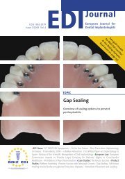
Figs. 15 to 24 represent various aspects and details of computer-assisted treatment planning for the maxilla: with Figures 15 to 18<br />
showing the three-dimensional model of the maxilla by itself, the maxilla complete with the planned implants, a cranial view<br />
that demonstrates numerous details of the maxillary anatomy and a frontal-occlusal view with the representation of the<br />
radiopaque denture: Note the exact correspondence between the drill holes in the scanning denture and the extensions of the<br />
implants. Figure 19 shows the vertical planes calculated by SimPlant for this three-dimensional model. Figures 20 to 24 show<br />
various software options for creating sections at every level, with a three-dimensional visualization of the orientations of the<br />
planned implants and a characteristic depiction of the individual implants in this particular pyramid-shaped configuration.<br />
15<br />
mechanically stable fixed complete denture (Fig. 14).<br />
The SimPlant interactive dental implant treatment<br />
planning tool let us work three-dimensionally to<br />
select implants of the appropriate diameters and<br />
lengths as a function of the available vertical and<br />
transversal bone supply. In addition, the tool helped<br />
us optimize the directions, angulations and emergence<br />
profiles to accommodate the prosthetic<br />
aspects of the case [25] (Figs. 15 to 24).