The OTIS Reference Manual - Hasylab
The OTIS Reference Manual - Hasylab
The OTIS Reference Manual - Hasylab

You also want an ePaper? Increase the reach of your titles
YUMPU automatically turns print PDFs into web optimized ePapers that Google loves.
5 Slow Control<br />
5.1 I 2 C Interface<br />
<strong>The</strong> slow control interface of the <strong>OTIS</strong> chips is a standard mode I 2 C slave device capable to transfer<br />
data at a transfer rate of 100kbit/s. <strong>The</strong> chip address, necessary to access a single device on the<br />
I 2 C bus, is assigned by means of the address padsID (LSB) toID (MSB) for chip versions<br />
1.1 to 1.3. For the chip version <strong>OTIS</strong>1.0 the pads are named ID (LSB) to ID (MSB). <strong>The</strong><br />
ID pads (see tables 8 to 11) contain internal pull down resistors. Note that the <strong>OTIS</strong> I 2 C interface<br />
does not respond to reserved I 2 C addresses. Reserved addresses are 7’b0000XXX and 7’b1111XXX.<br />
In other words, the valid addresses range from 8 to 119.<br />
Write mode:<br />
S<br />
Read mode:<br />
Preset pointer<br />
S<br />
Pointer set followed by immediate read−out<br />
S<br />
Slave Adr R/W<br />
6 0 0<br />
A<br />
Pointer Byte<br />
7 0<br />
Slave Adr R/W<br />
A<br />
Data Byte<br />
6 0 1 7 0<br />
Data Byte<br />
7 0<br />
n times<br />
Slave Adr R/W Pointer Byte<br />
Slave Adr<br />
A<br />
R/W<br />
A RS<br />
A<br />
6 0 0 7 0<br />
6 0 1<br />
From Master to Slave From Slave to Master<br />
A<br />
A<br />
Data Byte<br />
7 0<br />
A<br />
P<br />
Data Byte<br />
7 0<br />
n times<br />
P<br />
Data Byte<br />
A<br />
Data Byte<br />
7 0 7 0<br />
n times<br />
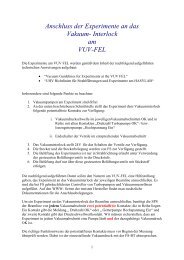
Figure 3: I 2 C-bus write and read sequences for accessing registers on the <strong>OTIS</strong> chip<br />
<strong>The</strong> internal registers can be accessed via the pointer register. This register contains the address<br />
of the following register to be written to or read from. <strong>The</strong> pointer is internally incremented<br />
by 1 after each transferred data frame. Thus registers with adjacent addresses are accessed consecutively.<br />
<strong>The</strong> content of the pointer register itself remains unchanged, i.e. a new transfer will<br />
start at the previously set pointer position. Figure 3 explains the transfer sequences in write and<br />
read mode. Data is always transferred with the most significant bit first. In write mode the chip<br />
address is transmitted after initializing the transfer, followed by the pointer byte and the data<br />
byte(s). After the transmission of one data frame, the write pointer addresses the next register due<br />
to its internal auto-incrementing functionality. <strong>The</strong> transfer of the pointer register is mandatory<br />
in write mode. For the read mode two possibilities exist:<br />
�Preset pointer: <strong>The</strong> data output immediately starts after the initialization and the transmission<br />
of the chip address. <strong>The</strong> pointer has been set in a previous I 2 C-data transfer.<br />
�New pointer: After initialization and transfer of the chip address, a new pointer byte gets<br />
programmed. <strong>The</strong>n, after re-initialization and re-transmission of the chip address, the data<br />
output starts.<br />
5.2 Configuration Registers<br />
<strong>The</strong> register map of the TDC chip changed between chip version <strong>OTIS</strong>1.0 and <strong>OTIS</strong>1.1 following<br />
the growing functional range. Note that not only the number of registers changed but also the bit<br />
assignment of single setup or status registers.<br />
8<br />
P