Creep-fatigue of High Temperature Materials for VHTR: Effect of ...
Creep-fatigue of High Temperature Materials for VHTR: Effect of ...
Creep-fatigue of High Temperature Materials for VHTR: Effect of ...

Create successful ePaper yourself
Turn your PDF publications into a flip-book with our unique Google optimized e-Paper software.
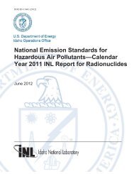
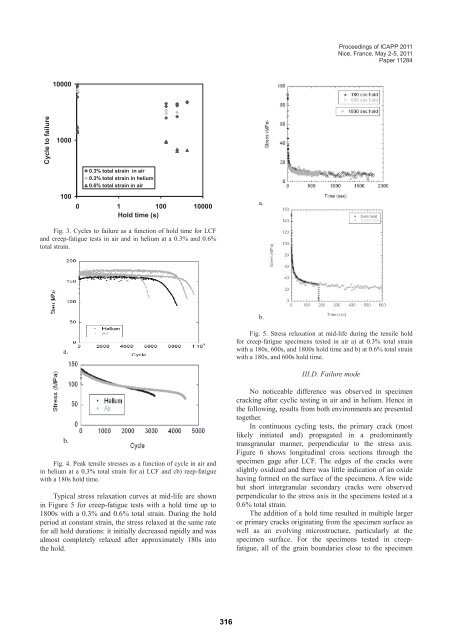
Cycle to failure<br />
10000<br />
1000<br />
100<br />
0.3% total strain in air<br />
0.3% total strain in helium<br />
0.6% total strain in air<br />
0,01 1 100 10000<br />
Hold time (s)<br />
Fig. 3. Cycles to failure as a function <strong>of</strong> hold time <strong>for</strong> LCF<br />
and creep-<strong>fatigue</strong> tests in air and in helium at a 0.3% and 0.6%<br />
total strain.<br />
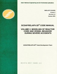
a.<br />
b.<br />
Fig. 4. Peak tensile stresses as a function <strong>of</strong> cycle in air and<br />
in helium at a 0.3% total strain <strong>for</strong> a) LCF and cb) reep-<strong>fatigue</strong><br />
with a 180s hold time.<br />
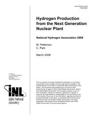
Typical stress relaxation curves at mid-life are shown<br />
in Figure 5 <strong>for</strong> creep-<strong>fatigue</strong> tests with a hold time up to<br />
1800s with a 0.3% and 0.6% total strain. During the hold<br />
period at constant strain, the stress relaxed at the same rate<br />
<strong>for</strong> all hold durations: it initially decreased rapidly and was<br />
almost completely relaxed after approximately 180s into<br />
the hold.<br />
316<br />
a.<br />
b.<br />
Proceedings <strong>of</strong> ICAPP 2011<br />
Nice, France, May 2-5, 2011<br />
Paper 11284<br />
Fig. 5. Stress relaxation at mid-life during the tensile hold<br />
<strong>for</strong> creep-<strong>fatigue</strong> specimens tested in air a) at 0.3% total strain<br />
with a 180s, 600s, and 1800s hold time and b) at 0.6% total strain<br />
with a 180s, and 600s hold time.<br />
III.D. Failure mode<br />
No noticeable difference was observed in specimen<br />
cracking after cyclic testing in air and in helium. Hence in<br />
the following, results from both environments are presented<br />
together.<br />
In continuous cycling tests, the primary crack (most<br />
likely initiated and) propagated in a predominantly<br />
transgranular manner, perpendicular to the stress axis.<br />
Figure 6 shows longitudinal cross sections through the<br />
specimen gage after LCF. The edges <strong>of</strong> the cracks were<br />
slightly oxidized and there was little indication <strong>of</strong> an oxide<br />
having <strong>for</strong>med on the surface <strong>of</strong> the specimens. A few wide<br />
but short intergranular secondary cracks were observed<br />
perpendicular to the stress axis in the specimens tested at a<br />
0.6% total strain.<br />
The addition <strong>of</strong> a hold time resulted in multiple larger<br />
or primary cracks originating from the specimen surface as<br />
well as an evolving microstructure, particularly at the<br />
specimen surface. For the specimens tested in creep<strong>fatigue</strong>,<br />
all <strong>of</strong> the grain boundaries close to the specimen