CVS 1000L Electro-Pneumatic Linear Positioner - CVS Controls
CVS 1000L Electro-Pneumatic Linear Positioner - CVS Controls
CVS 1000L Electro-Pneumatic Linear Positioner - CVS Controls

You also want an ePaper? Increase the reach of your titles
YUMPU automatically turns print PDFs into web optimized ePapers that Google loves.
Product Manual<br />
<strong>CVS</strong> <strong>1000L</strong> <strong>Electro</strong>-<strong>Pneumatic</strong> <strong>Linear</strong> <strong>Positioner</strong><br />
INTRODUCTION<br />
Thank you for choosing the YT-<strong>1000L</strong>. Each product<br />
is fully inspected after production to offer you the<br />
highest quality. In order to fully utilize the product, we<br />
strongly recommend users to read this manual<br />
carefully.<br />
�� The manual can be changed or revised without<br />
any prior notice. Any changes in the product’s<br />
specification, structure and/or any components<br />
may not result in an immediate revised version of<br />
the manual.<br />
�� The manual should not be duplicated or<br />
reproduced for any purpose without the approval<br />
of <strong>CVS</strong> <strong>Controls</strong> Ltd.<br />
MANUFACTURER WARRANTY<br />
- For safety, it is imperative to follow instructions in the<br />
manual. The manufacturer is not liable for any<br />
damages caused by the users negligence.<br />
- The manufacturer is not liable for any damages or<br />
accidents as a result of alterations or modifications<br />
made to the product or parts. If alterations or<br />
modifications are required, please contact<br />
<strong>CVS</strong> <strong>Controls</strong> Ltd.<br />
- The manufacturer warrants the product from the<br />
original date of purchase for one (1) year, except as<br />
otherwise stated.<br />
- The manufacturer warranty will be considered void<br />
should the product be subjected to abuse, faulty<br />
installation, lack of reasonable care, repair or service<br />
in any way, that is not contemplated in the<br />
documentation of the product, or if the model or serial<br />
number has been altered, tampered with, defaced, or<br />
removed; damages that occur in shipment, due to the<br />
act of God, failure due to power surge, and cosmetic<br />
damage. Improper or incorrectly performed<br />
maintenance also voids the Limited Warranty.<br />
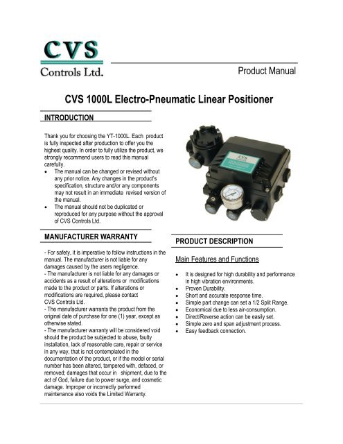
PRODUCT DESCRIPTION<br />
Main Features and Functions<br />
�� It is designed for high durability and performance<br />
in high vibration environments.<br />
�� Proven Durability.<br />
�� Short and accurate response time.<br />
�� Simple part change can set a 1/2 Split Range.<br />
�� Economical due to less air-consumption.<br />
�� Direct/Reverse action can be easily set.<br />
�� Simple zero and span adjustment process.<br />
�� Easy feedback connection.
2<br />
<strong>CVS</strong> <strong>Controls</strong> Ltd.<br />
Product Manual: <strong>CVS</strong> Rack & Pinion Actuator<br />
Operation Logic<br />
As the input signal is increased, the flapper (2) get pushed by the force of the torque-motor (1). As the<br />
gap between the flapper (2) and the nozzle (3) increases, air pressure bleeds from the pilot valve (4)<br />
and the spool (5). As a result, the spool (5) rises and simultaneously opens the seat (7). This allows air<br />
pressure to discharge through port OUT1 to the actuator (10). As the actuators inner pressure increases,<br />
the actuator stem (12) will move, pushing on the feedback lever (13). This movement is transferred to<br />
the cam (14) and pulls on the feedback spring (16). At the point of balanced force exerted by the input<br />
signal and the feedback spring, the gap between the flapper (2) and the nozzle (3) will decrease,<br />
stopping the movement to the actuator.<br />
<strong>CVS</strong> <strong>Controls</strong> Ltd.<br />
Process Management<br />
And Instrumentation
Specification<br />
CATEGORY<br />
3<br />
<strong>CVS</strong> <strong>Controls</strong> Ltd.<br />
Product Manual: <strong>CVS</strong> Rack & Pinion Actuator<br />
YT - <strong>1000L</strong><br />
Single Double<br />
Input Signal 4 ~ 20mA DC *1<br />
Impedance 250±15Ω<br />
Supply Pressure 1.4 ~ 7.0kgf/cm 2 (20 ~ 100psi)<br />
Stroke 10 ~ 150mm *2<br />
Air Connection 1/4’ NPT<br />
Gauge Connection 1/8” NPT<br />
Conduit Entry 1/2” NPT<br />
Explosion Proof<br />
CSA: Class 1, Zone 1, Group IIB, T5<br />
Protection IP66<br />
Ambient Operating<br />
Temperature<br />
-40 ~ 60°C<br />
<strong>Linear</strong>ity ±1.0% F.S<br />
Hysteresis 1.0% F.S<br />
Sensitivity ±0.2% F.S ±0.5% F.S<br />
Repeatability ±0.5% F.S<br />
Air Consumption 3LPM (Sup=1.4kgf/cm 2 , 20psi)<br />
Flow Capacity 80LPM (Sup=1.4kgf/cm 2 , 20psi)<br />
Material Aluminum Diecasting<br />
Weight 2.7 kg (6.1 lbs)<br />
* 1: For 1/2 Split Control, it can be applied by adjusting zero and span.<br />
* 2: For inquiries regarding strokes under 10mm or above 150mm, please contact <strong>CVS</strong> <strong>Controls</strong> Ltd.<br />
<strong>CVS</strong> <strong>Controls</strong> Ltd.<br />
Process Management<br />
And Instrumentation
4<br />
<strong>CVS</strong> <strong>Controls</strong> Ltd.<br />
Product Manual: <strong>CVS</strong> Rack & Pinion Actuator<br />
Parts and Assembly<br />
Dimensions<br />
Conduit Entry<br />
ZERO UNIT<br />
<strong>CVS</strong> <strong>Controls</strong> Ltd.<br />
Process Management<br />
And Instrumentation<br />
TORQUE<br />
MOTOR<br />
BASE BODY<br />
PT(NPT) 1/2<br />
PF(G) 1/2 Out 2<br />
JUNCTION<br />
BOX<br />
NONE<br />
Supply<br />
PT(NPT) 1/4<br />
224.3<br />
132.3 6<br />
45<br />
OUT 1<br />
122<br />
PT(NPT) 1/4<br />
166.<br />
Gauge<br />
PT(NPT) 1/8<br />
2-M8x1.25P 45<br />
23 27 32.5<br />
4-M8x1.25P<br />
33<br />
26.5<br />
43.5<br />
COVER<br />
PILOT VALVE<br />
FEEDBACK<br />
SHAFT<br />
SPAN UNIT<br />
VENT UNIT<br />
FEEDBACK<br />
LEVER<br />
35.5 91.8<br />
8<br />
37.2<br />
80.25
INSTALLATION<br />
Safety Warning<br />
When installing the positioner, please ensure you read<br />
and follow the safety instructions.<br />
�� All input and supply pressure to valve, actuator,<br />
and other related devices must be turned off.<br />
�� Use the bypass valve or other equipment to avoid<br />
an entire system “shut down”.<br />
�� Make sure there is no remaining pressure in the<br />
actuator.<br />
YT-<strong>1000L</strong> Installation<br />
YT-<strong>1000L</strong> should be installed on a linear motion valve<br />
such as a globe or gate valve using a spring return<br />
type diaphragm or piston actuator. Before installation,<br />
be sure to check for the following installation<br />
components.<br />
1. YT-<strong>1000L</strong> main body<br />
2. Feedback lever and lever spring<br />
3. Flange nut (bottom side of YT-<strong>1000L</strong>)<br />
4. 4 pcs. of hexagon head bolts (M8 X 1.25P)<br />
5. 4 pcs. of M8 plate washer<br />
Installation Steps:<br />
1. A proper bracket must be made in order to attach<br />
the positioner on the actuator yoke. Please consider<br />
the following when making a bracket.<br />
i) Feedback level should be leveled at 50% of the<br />
valve stroke. (Refer to step 7.)<br />
ii) Feedback lever connection bar of actuator clamp<br />
should be installed at the position that the valve stroke<br />
and number, indicated on the feedback, should be<br />
fitted. (Refer to step 8.)<br />
2. Attach YT-<strong>1000L</strong> to the bracket, which was<br />
produced in the earlier step, by using bolts. (Figure 2)<br />
Please refer to the backside of the product for size of<br />
bolts. The standard size of bolt is M8 X 1.25P.<br />
5<br />
<strong>CVS</strong> <strong>Controls</strong> Ltd.<br />
Product Manual: <strong>CVS</strong> Rack & Pinion Actuator<br />
3. Attach YT-<strong>1000L</strong> (with bracket) to the actuator yoke.<br />
DO NOT TIGHTEN COMPLETLEY.<br />
4. Connect YT-<strong>1000L</strong> feedback lever to the actuator<br />
clamp. The gap on the YT-<strong>1000L</strong> feedback lever is<br />
6.5mm. The connection bar thickness should be less<br />
than 6.3mm. (Figure 3)<br />
5. Connect the air filter regulator to the actuator temporarily.<br />
Set supply pressure of the regulator in order<br />
to position the actuator clamp at 50% of the valve<br />
stroke.<br />
(Figure 4 next page)<br />
50<br />
Max.6.3<br />
6.5mm<br />
<strong>CVS</strong> <strong>Controls</strong> Ltd.<br />
Process Management<br />
And Instrumentation
6<br />
<strong>CVS</strong> <strong>Controls</strong> Ltd.<br />
Product Manual: <strong>CVS</strong> Rack & Pinion Actuator<br />
YT-200<br />
6. Insert connection bar into the YT-<strong>1000L</strong> feedback<br />
lever. The connection bar should be inserted at the<br />
50% point on the feedback lever, which would help to<br />
reduce hysteresis.<br />
(Figure 5)<br />
7. If the connection bar does not point at the 50%<br />
point, then adjust the bracket or feedback link bar<br />
position. Failure to position at 50% would lower the<br />
linearity of the positioner.<br />
(Figure 6)<br />
<strong>CVS</strong> <strong>Controls</strong> Ltd.<br />
Process Management<br />
And Instrumentation<br />
40 50 60<br />
90°<br />
50%<br />
8. Check valve stroke. The stroke numbers are<br />
indicated on the feedback lever. Position the<br />
connection bar at the number on the feedback lever<br />
according to the valve stroke. To adjust, move the<br />
bracket or connection bar.<br />
(Figure 7)<br />
20 30<br />
Stroke 30mm<br />
Stroke 70mm<br />
40 50 60 70<br />
20 30 40 50 60<br />
NOTE: After installing the YT-<strong>1000L</strong>, operate the valve<br />
from 0% to 100% stroke by using the air filter regulator<br />
on the actuator. Both at 0% and 100%, the feedback<br />
lever should not touch the lever stopper, which is<br />
located on the backsideof the YT-<strong>1000L</strong>.<br />
(Figure 8)<br />
If the feedback lever touches the lever stopper,<br />
YT-<strong>1000L</strong> should be installed further away from the<br />
center of the yoke.<br />
9. After the proper installation, tighten all the bolts on<br />
the bracket, the feedback lever, and the connection<br />
bar.<br />
70
PIPING CONNECTION<br />
NOTE:<br />
�� To avoid moisture, oil, or dust from entering the<br />
product, please carefully select the supply<br />
pressure compressor.<br />
Supply Pressure Condition<br />
1. Dry air with at least 10°C lower than ambient<br />
temperature.<br />
2. Keep away from dusty air. Filter can only sort 5<br />
micron or larger.<br />
3. Avoid oil.<br />
4. Comply with ANSI/ISA-57.3 1975(R1981).<br />
5. Not to be used beyond the range of<br />
1.4 - 7 kgf/cm 2 (20 - 100 Psi).<br />
6. Set air filter regulator’s supplied pressure 10%<br />
higher than actuator’s spring range pressure.<br />
Pipe Condition<br />
1. Make sure the inside of the pipe is empty.<br />
2. Do not use pipeline that is squeezed or has holes.<br />
3. To maintain flow rate, use the pipeline that has<br />
more than a 6mm inner diameter.<br />
4. Do not use an extremely long pipeline system. It<br />
may affect flow rate due to the friction inside the<br />
pipeline.<br />
Piping Connection with Actuator<br />
YT-1000 series single acting type is set out to use<br />
OUT1 port. OUT1 port should be connected with the<br />
supply pressure port from the actuator when using<br />
single acting type spring return actuator. For double<br />
acting, the piping connection can be changed due to<br />
the operation direction. Please refer to the following<br />
diagrams when piping.<br />
(Figures 9 - 11)<br />
7<br />
OUT 2<br />
OUT 1<br />
OUT 2<br />
AIR<br />
SUPPLY<br />
AIR<br />
SUPPLY<br />
SUP. OUT 1<br />
YT-200<br />
<strong>CVS</strong> <strong>Controls</strong> Ltd.<br />
Product Manual: <strong>CVS</strong> Rack & Pinion Actuator<br />
SUP.<br />
OUT<br />
OUT 2 SUP.<br />
YT-200<br />
AIR<br />
SUPPLY<br />
OUT<br />
DIRECT<br />
ACTION<br />
OUT 1<br />
OUT 2<br />
INPUT<br />
SIGNAL<br />
4~20mA<br />
OUT1<br />
OUT 1<br />
OUT1<br />
OUT 2<br />
OUT 1<br />
OUT 2<br />
SUP. OUT 1<br />
AIR<br />
SUPPLY<br />
REVERSE<br />
ACTION<br />
<strong>CVS</strong> <strong>Controls</strong> Ltd.<br />
Process Management<br />
And Instrumentation
8<br />
<strong>CVS</strong> <strong>Controls</strong> Ltd.<br />
Product Manual: <strong>CVS</strong> Rack & Pinion Actuator<br />
POWER CONNECTION<br />
Connection - Connection Port<br />
1. Connection port size is 1/2” NPT.<br />
NOTE: REFER TO THE CANADIAN ELECTRICAL<br />
CODE FOR HAZARDOUS WIRING METHODS.<br />
Connection Power<br />
1. Open the terminal box cover.<br />
2. Locate the poles and connect them properly.<br />
Make sure to fasten the connection.<br />
3. Close the terminal box cover. (Figure15)<br />
Upper Side<br />
Lower Side<br />
<strong>CVS</strong> <strong>Controls</strong> Ltd.<br />
Process Management<br />
And Instrumentation<br />
Ground<br />
Black (-)<br />
Red (+)<br />
ADJUSTMENT<br />
Adjustment - Zero Point<br />
1. Set supply signal at 4mA or 20mA and rotate<br />
adjuster clockwise or counter-clockwise to adjust the<br />
actuator’s initial point. When setting the initial point,<br />
the specification of valve and system must be taken<br />
into account. Please refer to Figure 17 for<br />
increase/decrease of the zero point.<br />
2. When a single acting actuator with spring is used,<br />
please check if the pressure level, which is indicated<br />
on the positioner, is the same as the supplied pressure<br />
level.
Adjustment - Span<br />
1. After setting zero, supply 20mA or 4mA of signal.<br />
Check the actuator’s stroke. If the stroke is too low,<br />
adjust the span towards the (+) direction.<br />
If the stroke point is too high, adjust the span towards<br />
the (-) direction. (Figure 18)<br />
2. Changing span points affects the zero point setting,<br />
so the zero setting must be set again. After setting<br />
zero point, confirm the span point. This step must be<br />
repeated until both points are properly set.<br />
3. After setting is completed, tighten lock screw.<br />
Lock Screw<br />
Adjustment - A/M Switch (Auto/Manual)<br />
1. A/M switch adjusts the valve operation to automatic<br />
or manual.<br />
2. When produced, YT-<strong>1000L</strong> is set at “A(Automatic)”.<br />
If user prefers the positioner setting as “M(Manual)”,<br />
the setting can be changed by turning the switch<br />
counter-clockwise. (Figure 19)<br />
3. If it is set as “M(Manual)”, the air pressure will be<br />
supplied to the actuator directly. Always set back to<br />
“A(Automatic)” after setting change.<br />
4. If OUT2 in single acting actuator or double acting<br />
actuator is used, the A/M switch will not operate.<br />
9<br />
Adjustment - Seat Adjuster<br />
1. Seat adjustment is set according to the customers<br />
request before the positioner is delivered. Please do<br />
not adjust the seat adjuster.<br />
2. Seat adjuster is always used for double acting<br />
actuators and adjusted when the pressure balance<br />
point must be changed. Please do not touch the seat<br />
adjuster, because it can affect the positioner’s<br />
performance.<br />
Output<br />
Pressure<br />
Output<br />
Pressure<br />
Output<br />
Pressure<br />
Input Pressure<br />
Adjustment - Orifice<br />
<strong>CVS</strong> <strong>Controls</strong> Ltd.<br />
Product Manual: <strong>CVS</strong> Rack & Pinion Actuator<br />
Lock Screw<br />
Auto Manual Switch<br />
Balanced Point<br />
Balanced Point<br />
Balanced Point<br />
Seat Adjuster<br />
High Pressure Balance<br />
(0.9~1.0Ps) - Normal<br />
Med. Pressure Balance<br />
(0.5Ps) - Normal<br />
Low Pressure Balance<br />
(0.4~0.5Ps) - Normal<br />
Ps=Supply Pressure<br />
1. If the size of the actuator is too small relative to the<br />
flow rate, the positioner can have hunting. In order to<br />
avoid hunting, orifice can be used. There are three<br />
types of orifice.<br />
<strong>CVS</strong> <strong>Controls</strong> Ltd.<br />
Process Management<br />
And Instrumentation
10<br />
<strong>CVS</strong> <strong>Controls</strong> Ltd.<br />
Product Manual: <strong>CVS</strong> Rack & Pinion Actuator<br />
Actuator Size Orifice Size Suffix Symbol<br />
90 cm 3 less O 1 1<br />
90 - 180 cm 3 O 2 2<br />
180 cm 3 more none 3<br />
2. Remove the o-ring from OUT1 and OUT2 port and<br />
insert appropriate orifice. After inserting orifice, replace<br />
the o-ring. Make sure there are not any substances<br />
entering into the port. (Figure 21)<br />
3. If hunting persists after inserting the orifice, please<br />
contact <strong>CVS</strong> <strong>Controls</strong> Ltd. or its appropriate agent.<br />
Orifice<br />
Orifice Diameter<br />
TROUBLESHOOTING<br />
►<strong>Positioner</strong> does not respond to the input<br />
signal.<br />
1. Check supply pressure level. The lever must be at<br />
least 1.4 kgf/cm 2. For spring return type actuator, the<br />
supply pressure level has to be larger than the spring’s<br />
specification.<br />
2. Check if the input signal is properly supplied to the<br />
positioner. The signal should be 4~20mA DC.<br />
3. Check if zero pint or span point is properly set.<br />
4. Check if the positioners nozzle has been blocked.<br />
Also, check if the pressure is supplied to<br />
the positioner and the pressure is being exhausted<br />
through the nozzle. If the nozzle has been blocked by<br />
any substances, please send the product for repair.<br />
5. Check if the feedback lever has been installed<br />
properly.<br />
<strong>CVS</strong> <strong>Controls</strong> Ltd.<br />
Process Management<br />
And Instrumentation<br />
O - Ring (P5)<br />
OUT2 OUT1<br />
►The pressure of OUT1 reaches exhausting<br />
pressure level and does not decrease.<br />
1. Check A/M Switch. If the switch has been damaged,<br />
replace the switch or pilot relay valve.<br />
2. Check for a gap or damages between the nozzle<br />
and the flapper. If damaged, pleae contact<br />
<strong>CVS</strong> <strong>Controls</strong> Ltd.<br />
►The pressure is exhausted only by the A/M<br />
switch.<br />
1. Check if the positioners nozzle has been<br />
blocked. Also, check if the pressure is supplied<br />
to the positioner and the pressure is being<br />
exhausted through the nozzle. If the nozzle has been<br />
blocked by any substances, please contact<br />
<strong>CVS</strong> <strong>Controls</strong> Ltd.<br />
►<strong>Linear</strong>ity is too low<br />
1. Check if the positioner is properly positioned.<br />
Especially if the feedback lever is parallel to the<br />
ground at 50% point.<br />
2. Check if zero and span point have been properly<br />
adjusted. If either one of the values is being adjusted,<br />
another one must be adjusted as well.<br />
3. Check if the supply air pressure level is stable from<br />
the regulator. If the level is unstable, the regulator<br />
must be replaced.<br />
►Hysteresis is too low<br />
1. In case of a double acting actuator, check if seat<br />
adjustment has been properly performed. Please<br />
contact <strong>CVS</strong> for any further inquiries regarding the<br />
seat adjustment.<br />
2. Backlash can ccur when the feedback lever and<br />
lever spring loosen. To avoid backlashing, please<br />
adjust the lever spring.<br />
3. Check if the connection bar to the feedback lever is<br />
tightly fastened.
NOTES:<br />
11<br />
<strong>CVS</strong> <strong>Controls</strong> Ltd.<br />
Product Manual: <strong>CVS</strong> Rack & Pinion Actuator<br />
<strong>CVS</strong> <strong>Controls</strong> Ltd.<br />
Process Management<br />
And Instrumentation
Head Office<br />
3900 – 101 Street<br />
Edmonton, Alberta, Canada T6E 0A5<br />
Office: (780) 437-3055<br />
Fax: (780) 436-5461<br />
Calgary Sales Office<br />
205, 2323 – 32 Avenue NE<br />
Calgary, Alberta, Canada T2E 6Z3<br />
Office: (403) 250-1416<br />
Fax: (403) 291-9487<br />
Website: www.cvs-controls.com E-Mail: info@cvs-controls.com<br />
12