CVS 1200 Pneumatic Positioner Linear and Rotary - CVS Controls
CVS 1200 Pneumatic Positioner Linear and Rotary - CVS Controls
CVS 1200 Pneumatic Positioner Linear and Rotary - CVS Controls

You also want an ePaper? Increase the reach of your titles
YUMPU automatically turns print PDFs into web optimized ePapers that Google loves.
INSTRUCTION MANUAL<br />
<strong>CVS</strong> <strong>1200</strong> <strong>Pneumatic</strong><br />
<strong>Positioner</strong><br />
<strong>Linear</strong> <strong>and</strong> <strong>Rotary</strong><br />
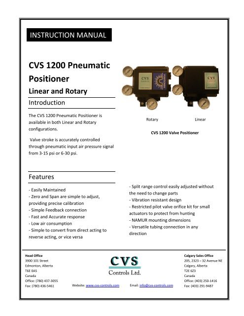
Introduction<br />
The <strong>CVS</strong> <strong>1200</strong> <strong>Pneumatic</strong> <strong>Positioner</strong> is<br />
available in both <strong>Linear</strong> <strong>and</strong> <strong>Rotary</strong><br />
configurations.<br />
Valve stroke is accurately controlled<br />
through pneumatic input air pressure signal<br />
from 3-15 psi or 6-30 psi.<br />
Features<br />
- Easily Maintained<br />
- Zero <strong>and</strong> Span are simple to adjust,<br />
providing precise calibration<br />
- Simple Feedback connection<br />
- Fast <strong>and</strong> Accurate response<br />
- Low air consumption<br />
- Simple to convert from direct acting to<br />
reverse acting, or vice versa<br />
Head Office<br />
3900 101 Street<br />
Edmonton, Alberta<br />
T6E 0A5<br />
Canada<br />
Office: (780) 437-3055<br />
Fax: (780) 436-5461<br />
<strong>CVS</strong> <strong>1200</strong> Valve <strong>Positioner</strong><br />
- Split range control easily adjusted without<br />
the need to change parts<br />
- Vibration resistant design<br />
- Restricted pilot valve orifice kit for small<br />
actuators to protect from hunting<br />
- NAMUR mounting dimensions<br />
- Versatile tubing connection in any<br />
direction<br />
Website: www.cvs-controls.com Email: info@cvs-controls.com<br />
<strong>Rotary</strong> <strong>Linear</strong><br />
Calgary Sales Office<br />
205, 2323 – 32 Avenue NE<br />
Calgary, Alberta<br />
T2E 6Z3<br />
Canada<br />
Office: (403) 250-1416<br />
Fax: (403) 291-9487<br />
1
Specifications<br />
<strong>CVS</strong> <strong>1200</strong> <strong>Positioner</strong> <strong>Linear</strong> <strong>Rotary</strong><br />
Input Signal 3-15 psi/6-30 psi (0.2 – 1.0 kgf/cm 2 )<br />
Supply Pressure 20 – 100 psi (1.4 – 7.0 kgf/cm 2 )<br />
Stroke 10 – 150 mm 0 – 90 degrees<br />
Air Connection 1/4 NPT<br />
Gauge Connection 1/8 NPT<br />
Protection IP67<br />
Ambient Pressure -40 0 C – 70 0 C<br />
<strong>Linear</strong>ity ± 1% F.S. ± 2% F.S.<br />
Hysteresis 1% F.S.<br />
Sensitivity ±0.2% F.S. ±0.5% F.S.<br />
Repeatability ±0.5%<br />
Air Consumption 3 LPM (Sup = 20 psi, 1.4kgf/cm 2 )<br />
Flow Capacity 80 LPM (Sup = 20 psi, 1.4kgf/cm 2 )<br />
Housing Material Aluminum Alloy<br />
Approx. Weight 3.7lb (1.7kg)<br />
<strong>CVS</strong> <strong>1200</strong> <strong>Linear</strong> <strong>Positioner</strong><br />
2
Installation<br />
<strong>Linear</strong>:<br />
1. Mount bracket with two 5/16”x1”<br />
bolts to actuator. Leave bolts loose at<br />
this point.<br />
2. Mount positioner to bracket with<br />
two 8mmx1-1/2 bolts <strong>and</strong> spacers.<br />
Leave bolts loose at this point<br />
3. Install threaded shaft into<br />
connecting block.<br />
4. Apply air to actuator until valve is<br />
at 50%.<br />
5. Using link bearings <strong>and</strong> link,<br />
connect from threaded shaft to<br />
positioner travel arm.<br />
Note: Travel arm is metric.<br />
6. Tighten link bearings to travel arm<br />
with ¼” bolt <strong>and</strong> nut. Adjust nuts on<br />
threaded shaft until link is parallel<br />
with actuator. Then tighten.<br />
7. Slide positioner until link is parallel<br />
with actuator stem. Tighten bolts.<br />
8. Adjust link so that the travel arm<br />
forms a right angle to the actuator.<br />
Tighten bolts.<br />
9. Apply air to actuator until travel is<br />
100%. Inspect to ensure travel arm is<br />
not touching stopper on back side of<br />
the positioner. If so, adjust link<br />
bearing bolt on travel arm<br />
accordingly.<br />
10. Remove air from actuator <strong>and</strong><br />
inspect down travel stop. Adjust<br />
accordingly.<br />
3
<strong>Rotary</strong>:<br />
The <strong>CVS</strong> <strong>1200</strong> <strong>Positioner</strong> comes with<br />
st<strong>and</strong>ard NAMUR bracket, optional<br />
brackets available. The bracket may<br />
be used for Fork Lever, or NAMUR<br />
bracket.<br />
St<strong>and</strong>ard actuator stem height is 20,<br />
30, or 50mm. After checking stem<br />
height assemble with bracket as<br />
required.<br />
Attach bracketed <strong>CVS</strong><strong>1200</strong>R to the<br />
actuator using hex-head bolts.<br />
Bracket mounting hole is 6mm. Use<br />
lock washer on fasteners for firm<br />
attachment to the actuator, so the<br />
<strong>CVS</strong> <strong>1200</strong> positioner will not shake<br />
from vibration or any other impact.<br />
The direction of the bracket is<br />
determined by the operating<br />
condition.<br />
Set rotation position of the actuator<br />
stem at zero point, “0%”. Single<br />
acting actuator stem will be at zero<br />
point when there is no supply<br />
pressure. If a double acting actuator<br />
is being used, check the actuator<br />
stem rotation (clockwise, or counter<br />
clockwise) by supplying pressure.<br />
Install the fork lever after setting the<br />
actuator stem at zero point. Check<br />
the direction of the actuator stem –<br />
clockwise or counterclockwise.<br />
Installation angle of the fork lever<br />
should be 45 degrees based on the<br />
linear shaft. For NAMUR shaft the<br />
angle does not matter.<br />
Upon setting fork lever position,<br />
tighten lock nuts which are<br />
assembled on bottom of fork lever.<br />
Attach <strong>CVS</strong> <strong>1200</strong>R to the bracket. Fix<br />
the clamping pin on the main shaft of<br />
the positioner <strong>and</strong> insert connection<br />
bar onto the fork lever slot so that it<br />
may be locked to the fork lever<br />
spring. This sets the alignment of the<br />
main shaft of the positioner <strong>and</strong> the<br />
center of the actuator stem. Poor<br />
alignment of the actuator stem may<br />
lower durability of the <strong>CVS</strong> <strong>1200</strong> due<br />
to excessive force on the main shaft<br />
of the positioner.<br />
Tighten positioner base <strong>and</strong> bracket<br />
with hex head bolts <strong>and</strong> lock washer.<br />
It is recommended to tighten four<br />
bolts after verifying the <strong>CVS</strong> <strong>1200</strong>’s<br />
position.<br />
4
<strong>Pneumatic</strong> Input Adjustment<br />
Procedure:<br />
Factory setting for input is 3-15 psi.<br />
The <strong>CVS</strong> <strong>1200</strong> <strong>Positioner</strong> is easily<br />
changed to 6-30 psi.<br />
1. Ensure air supply is removed from<br />
unit.<br />
2. Using a 7mm wrench, loosen lock<br />
nut on threaded shaft.<br />
3. Using pliers, remove spring from<br />
zero adjust post.<br />
4. Remove span spring from threaded<br />
shaft.<br />
5. Using the zero spring, turn the<br />
threaded shaft one full rotation<br />
clockwise.(towards span adjuster)<br />
6. Reattach zero spring to post, <strong>and</strong><br />
span spring to shaft. Tighten jam nut<br />
on threaded shaft.<br />
Continue with calibration.<br />
Note: Should additional span<br />
adjustment be required, another turn<br />
on the threaded shaft may be<br />
achieved.<br />
2.<br />
3.<br />
4.<br />
5.<br />
6.<br />
5
<strong>Linear</strong> <strong>and</strong> <strong>Rotary</strong>:<br />
Zero Adjustment-<br />
1. Set signal to the stroke starting<br />
signal (3 psi) then turn the Zero<br />
Adjuster clockwise or counter<br />
clockwise accordingly.<br />
2. In the case of a spring actuator,<br />
check to see if it is set to st<strong>and</strong>ard<br />
pressure in zero point. If not, repeat<br />
Zero Adjustment.<br />
<strong>Linear</strong> <strong>and</strong> <strong>Rotary</strong>:<br />
Span Adjustment-<br />
1. Turn <strong>and</strong> adjust the Span<br />
Adjustment Screw, so that the<br />
indicator reads at final stroke point<br />
by final input signal.<br />
2. Check Zero Point, <strong>and</strong> repeat Zero<br />
Span Adjustment. ½ Split Range can<br />
be used by Zero <strong>and</strong> Span<br />
Adjustments.<br />
3. Tighten Lock Screw of Span<br />
adjustment after setting.<br />
Zero Adjustment – <strong>Linear</strong> <strong>and</strong> <strong>Rotary</strong><br />
Span Adjustment - <strong>Linear</strong><br />
Span Adjustment - <strong>Rotary</strong><br />
6
Auto/Manual Switch-<br />
1. Factory setting is Auto. To use<br />
manual operation, turn A/M Switch<br />
counterclockwise.<br />
2. In manual operation, the pressure<br />
of a <strong>CVS</strong> regulator connects to<br />
actuator. After using, return switch to<br />
“A”.<br />
Seat Adjuster-<br />
The Seat Adjuster is adjusted <strong>and</strong> set<br />
prior to shipment for balanced<br />
pressure point of output pressure.<br />
There should be no need for<br />
adjustment.<br />
Seat adjuster is always used for<br />
double acting configurations. Should<br />
there be a need to change the<br />
balanced pressure point, use the seat<br />
adjuster.<br />
- Should the sensitivity be poor due<br />
to actuator type of load condition,<br />
turn the Seat Adjuster Screw<br />
clockwise. (The stopper screw is set<br />
to avoid the removal of the seat<br />
adjuster screw, do not loosen the<br />
stopper screw at this time.)<br />
Auto/Manual Switch<br />
Seat Adjuster<br />
Lock Screw<br />
7
<strong>Pneumatic</strong> Piping Conditions-<br />
- Fully purge the piping from debris.<br />
- Use clean air, fully removed of<br />
humidity <strong>and</strong> dust.<br />
- Use a <strong>CVS</strong> filter regulator to<br />
maintain constant supply pressure.<br />
- When using a double action<br />
positioner as a single acting type,<br />
close off either OUT1 or OUT2 <strong>and</strong><br />
remove pressure gauge to close its<br />
connection.<br />
Pilot Valve-<br />
When the positioner is attached to a<br />
small capacity actuator, hunting may<br />
occur. In this situation a pilot valve<br />
with a smaller output orifice may be<br />
used for OUT1 <strong>and</strong> OUT 2. The output<br />
orifice is interchangeable.<br />
Using a Phillips screwdriver remove 4<br />
screws <strong>and</strong> relay. Turn relay upside<br />
down.<br />
Upon removing the O-ring from<br />
OUT1 <strong>and</strong> OUT2, place the<br />
appropriate orifice in <strong>and</strong> re install<br />
the O-Ring to OUT1 <strong>and</strong> OUT2. Re<br />
install relay.<br />
Ensure that dust <strong>and</strong> debris does not<br />
enter the port hole when installing<br />
the output orifice.<br />
Should hunting not be resolved by<br />
installing output orifice, contact a<br />
<strong>CVS</strong> <strong>Controls</strong> Representative.<br />
Actuator Output Orifice Part Number<br />
Volume Diameter<br />
Below 90 cm 3 0.7 Contact <strong>CVS</strong><br />
90 – 180 cm 3 1.0 Contact <strong>CVS</strong><br />
Over 180 cm 3 N/A<br />
OUT 2<br />
OUT 1<br />
8
Maintenance <strong>and</strong> Inspection<br />
Ensure the supply air is clean <strong>and</strong> free<br />
from debris.<br />
Should the pilot valve be<br />
disassembled, apply grease to the<br />
sliding section.<br />
If the fixed orifice becomes clogged<br />
with carbon particles, or similar,<br />
remove the pilot valve Auto/Manual<br />
changeover screw <strong>and</strong> clean it using a<br />
Ø0.2 wire into the aperture. If it must<br />
be removed <strong>and</strong> replaced with a new<br />
one, ensure supply pressure has been<br />
relieved <strong>and</strong> remove the stopper<br />
screw of the pilot valve.<br />
Inspect the positioner once a year.<br />
Replace excessively worn parts as<br />
required. Extreme working conditions<br />
may require increased inspection<br />
intervals.<br />
CARE<br />
Large vibrations may cause improper<br />
operation of the <strong>CVS</strong> <strong>1200</strong> positioner.<br />
Extreme conditions outside of the<br />
operating temperature range may<br />
cause deterioration of the seals, <strong>and</strong><br />
improper operation.<br />
Ensure supply air is free from dust<br />
<strong>and</strong> humidity.<br />
Should the postioner be on site for<br />
long periods of time not operational,<br />
consider covering it so as to not let<br />
the weather elements get into the<br />
positioner.<br />
9
NOTES:<br />
10
NOTES:<br />
<strong>CVS</strong> <strong>Controls</strong> Ltd. strives for the highest levels of quality <strong>and</strong> accuracy. The information included in this publication is presented for<br />
informational purposes only. <strong>CVS</strong> <strong>Controls</strong> Ltd. reserves the right to modify or change, <strong>and</strong> improve design, process, <strong>and</strong> specifications<br />
without written notice. Under no circumstance is the information contained to be interpreted to be a guarantee/warranty with regard<br />
to our products or services, applicability or use.<br />
Selection, use <strong>and</strong> maintenance are the sole responsibility of the end user <strong>and</strong> purchaser. <strong>CVS</strong> <strong>Controls</strong> assumes no liability for the<br />
selection use <strong>and</strong> maintenance of any product.<br />
11
Head Office<br />
3900 101 Street<br />
Edmonton, Alberta<br />
T6E 0A5<br />
Canada<br />
Office: (780) 437-3055<br />
Fax: (780) 436 5461<br />
Calgary Sales Office<br />
205, 2323 – 32 Avenue NE<br />
Calgary, Alberta<br />
T2E 6Z3<br />
Canada<br />
Office: (403) 250-1416<br />
Fax: (403) 291-9487<br />
Website: www.cvs-controls.com Email: info@cvs-controls.com<br />
Rev 0, Oct/09<br />
12