cvs 2400 series smart positioner product description - CVS Controls
cvs 2400 series smart positioner product description - CVS Controls
cvs 2400 series smart positioner product description - CVS Controls

Create successful ePaper yourself
Turn your PDF publications into a flip-book with our unique Google optimized e-Paper software.
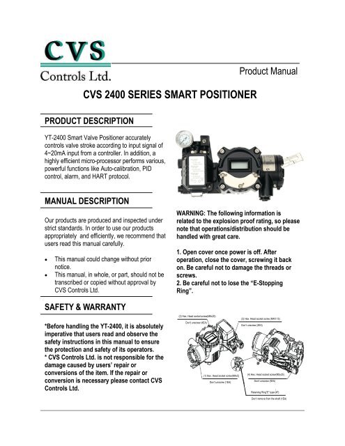
<strong>CVS</strong> <strong>2400</strong> SERIES SMART POSITIONER<br />
PRODUCT DESCRIPTION<br />
YT-<strong>2400</strong> Smart Valve Positioner accurately<br />
controls valve stroke according to input signal of<br />
4~20mA input from a controller. In addition, a<br />
highly efficient micro-processor performs various,<br />
powerful functions like Auto-calibration, PID<br />
control, alarm, and HART protocol.<br />
MANUAL DESCRIPTION<br />
Our <strong>product</strong>s are produced and inspected under<br />
strict standards. In order to use our <strong>product</strong>s<br />
appropriately and efficiently, we recommend that<br />
users read this manual carefully.<br />
�� This manual could change without prior<br />
notice.<br />
�� This manual, in whole, or part, should not be<br />
transcribed or copied without approval by<br />
<strong>CVS</strong> <strong>Controls</strong> Ltd.<br />
SAFETY & WARRANTY<br />
*Before handling the YT-<strong>2400</strong>, it is absolutely<br />
imperative that users read and observe the<br />
safety instructions in this manual to ensure<br />
the protection and safety of its operators.<br />
* <strong>CVS</strong> <strong>Controls</strong> Ltd. is not responsible for the<br />
damage caused by users’ repair or<br />
conversions of the item. If the repair or<br />
conversion is necessary please contact <strong>CVS</strong><br />
<strong>Controls</strong> Ltd.<br />
Product Manual<br />
WARNING: The following information is<br />
related to the explosion proof rating, so please<br />
note that operations/distribution should be<br />
handled with great care.<br />
1. Open cover once power is off. After<br />
operation, close the cover, screwing it back<br />
on. Be careful not to damage the threads or<br />
screws.<br />
2. Be careful not to lose the “E-Stopping<br />
Ring”.<br />
(2) Hex. Head socket screw(M6x20)<br />
Don’t unscrew (4EA)<br />
(1) Hex. Head socket screw(M4x5)<br />
Don’t unscrew (1EA)<br />
(3) Hex. Head socket screw (M4X 15)<br />
Don’t unscrew (2EA)<br />
(4) Hex. Head socket screw(M5x25)<br />
Don’t unscrew (5EA)<br />
Retaining Ring”E” type (#7)<br />
Don’t remove from the shaft (1EA)
<strong>CVS</strong> <strong>Controls</strong> Ltd.<br />
Product Manual: YT-<strong>2400</strong> Smart Positioner<br />
Notes on Maintenance of Explosion Proof Structure in Hazardous Area<br />
�� Confirm the operating conditions so that the<br />
explosion proof rating is available and ensure<br />
not to use beyond that rating.<br />
�� The explosion proof of the YT-<strong>2400</strong> is<br />
flame-proof, which is marked ExdIIBT6. and<br />
can be used in Zone 1 & 2.<br />
�� In hazardous areas with explosive gas,<br />
ensure connecting explosion proof conduit or<br />
pressure-proof packing cable must be sealed<br />
using a gasket.<br />
<strong>CVS</strong> <strong>Controls</strong> Ltd.<br />
Process Management<br />
And Instrumentation<br />
�� Confirm that the power is shut off before<br />
opening the cover.<br />
�� When opening the PCB Terminal or cover, of<br />
the terminal or PCB, the current or voltage must<br />
not remain in the wires or electronic parts after<br />
the power is shut down.<br />
�� YT-<strong>2400</strong> has two conduit entries. When one<br />
explosion proof conduit or pressure-proof<br />
packing cable is used, the other port must be<br />
blocked to ensure explosion proof rating.<br />
2
FEATURES and FUNCTIONS<br />
1. There are four buttons on the outside of the <strong>positioner</strong><br />
which allows for adjustment of parameters<br />
and menus without opening the cover in explosive<br />
gas areas.<br />
2. The <strong>smart</strong> <strong>positioner</strong> is ExdIIBT6 explosion proof<br />
rated.<br />
3. Endures severe vibration.<br />
4. The pilot relay valve is installed on the outside of<br />
the <strong>positioner</strong> body, which allows for easy<br />
serviceability.<br />
5. It operates normally regardless of the change in<br />
supply pressure during operation.<br />
6. This <strong>positioner</strong> is easy to auto-calibrate.<br />
7. Its compact size allows for easy installation on<br />
small actuators.<br />
8. Plant operating costs may be reduced due to its<br />
low air consumption.<br />
9. Due to the low voltage (8.5V) usage, there is no<br />
limitations with the controller.<br />
10. An adjustable orifice is used to accommodate<br />
small actuators so control is optimized during<br />
operation.<br />
11.The valve <strong>positioner</strong> has HART communication<br />
capability.<br />
12. The <strong>positioner</strong> output uses an analog feedback<br />
system.<br />
13. An alarm function is available when using a limit<br />
switch.<br />
14. Available valve flow characteristics are linear,<br />
quick opening, and equal percent.<br />
<strong>CVS</strong> <strong>Controls</strong> Ltd.<br />
Product Manual: YT-<strong>2400</strong> Smart Positioner<br />
15. Specific flow control is available with 16<br />
specified user points.<br />
16. Tight shut-off and open can be set by the user.<br />
17. Regulated filtered air flows to the actuator by<br />
using the A/M switch.<br />
18. Split range input is 4-20mA, 12-20mA.<br />
19. The Hand Calibration function can be used to<br />
set zero and span.<br />
20.The <strong>positioner</strong> has a self diagnose function for<br />
greater reliability.<br />
21. It is equipped with a manual override.<br />
22. The protection class is IP 66.<br />
23. The epoxy powder coating allows for long<br />
periods of exposure to a corrosive environment.<br />
24. Very easy to maintain with its modular design.<br />
(10-30V)<br />
4~20 mA<br />
INPUT<br />
Feed Back Signal<br />
V+<br />
OUT<br />
V-<br />
V+<br />
OUT<br />
V-<br />
3 <strong>CVS</strong> <strong>Controls</strong> Ltd.<br />
Process Management<br />
And Instrumentation<br />
Limit<br />
Limit<br />
V+<br />
OUT<br />
Limit Switch Circuit<br />
OUT<br />
Voltage<br />
V-<br />
load<br />
Detecting<br />
Limit<br />
Load<br />
Out Voltage<br />
Circuit
<strong>CVS</strong> <strong>Controls</strong> Ltd.<br />
Product Manual: YT-<strong>2400</strong> Smart Positioner<br />
STRUCTURE<br />
The structure of the YT-<strong>2400</strong>L is as follows. The YT-<strong>2400</strong>R is the same as the linear type except for the<br />
feedback lever.<br />
<strong>CVS</strong> <strong>Controls</strong> Ltd.<br />
Process Management<br />
And Instrumentation<br />
Terminal Cover<br />
Main Shaft<br />
Feedback Spring<br />
Potentiometer<br />
Terminal Plate<br />
Button Cover<br />
Body Cover<br />
Feedback Lever<br />
Main<br />
PCB<br />
Flange Nut<br />
Piezo<br />
4<br />
Manifold<br />
Pilot Relay Cover<br />
Pilot<br />
Relay<br />
Base Body<br />
YT-<strong>2400</strong>L (Linear Type) YT-<strong>2400</strong>R (Rotary Type)<br />
Variable Orifice<br />
Filter Plug
FEATURES & FUNCTIONS<br />
<strong>CVS</strong> <strong>Controls</strong> Ltd.<br />
Product Manual: YT-<strong>2400</strong> Smart Positioner<br />
5 <strong>CVS</strong> <strong>Controls</strong> Ltd.<br />
Process Management<br />
And Instrumentation
<strong>CVS</strong> <strong>Controls</strong> Ltd.<br />
Product Manual: YT-<strong>2400</strong> Smart Positioner<br />
INSTALLATION<br />
NOTE: When the <strong>positioner</strong> is installed or<br />
replaced with the actuator, ensure the following:<br />
WARNING: To avoid damage to the process<br />
system or personal injury, isolate the valve from<br />
the system and relieve any pressure contained<br />
within prior to disassembly. Disconnect any<br />
operating lines providing air pressure, control<br />
signals, or electrical power to the actuator.<br />
157.9<br />
142.5<br />
12<br />
12<br />
4-M8 TAP<br />
YT-<strong>2400</strong>R Drawing<br />
157.9<br />
142.5<br />
12<br />
30<br />
4-M3 TAP<br />
<strong>CVS</strong> <strong>Controls</strong> Ltd.<br />
Process Management<br />
And Instrumentation<br />
327.9<br />
252.4<br />
252.4<br />
50<br />
50<br />
5<br />
5<br />
6<br />
140.5<br />
156.5<br />
60<br />
60<br />
YT-<strong>2400</strong>L Drawing<br />
90.9<br />
TOOLS FOR INSTALLATION<br />
Tools and bolts used for assembly are:<br />
1. Hexagonal wrenches<br />
2. (+) screw driver<br />
3. (-) screw driver<br />
4. Spanners for hexagon head bolts<br />
YT-<strong>2400</strong>L Installation<br />
YT-<strong>2400</strong>L is used for linear motion valves such as<br />
globe valves or gate valves using spring return<br />
type diaphragm actuators or piston actuators.<br />
YT-<strong>2400</strong>L consists of the following components.<br />
Be sure that all the components are prepared.<br />
1. YT-<strong>2400</strong> body<br />
2. Feedback lever and spring lever<br />
3. Flange nut (attached on the body of the main<br />
shaft of the YT-<strong>2400</strong>L body)<br />
4. 4 pcs of hexagon head bolt M8x1.25P<br />
5. 4 pcs of M8 plate washer<br />
YT-<strong>2400</strong> Installation Example<br />
6
Installing YT-<strong>2400</strong>L with Bracket<br />
1. It is necessary to make a proper bracket to<br />
attach onto the actuator yoke.<br />
The most important notes in making the bracket<br />
are as follows:<br />
A) YT-<strong>2400</strong>L feedback lever should be level at<br />
50% of the valve stroke (Refer to point #7)<br />
B) Feedback lever connection bar of the actuator<br />
clamp should be connected at the position that the<br />
valve and stroke numbers engraved on the<br />
feedback lever match. (Refer to point #8)<br />
If the bracket meets the above conditions,<br />
installation of the YT-<strong>2400</strong>L is simple.<br />
2. Assemble the YT-<strong>2400</strong>L and bracket with<br />
supplied bolts.<br />
Installing YT-<strong>2400</strong>L with Bracket<br />
3. After assembling the YT-<strong>2400</strong>L attach it using<br />
the bolt holes of the actuator yoke. Do not tighten<br />
bolts completely - there must be some space<br />
remaining.<br />
4. Install the bar connected to the YT-<strong>2400</strong><br />
feedback lever on the actuator clamp. The slot<br />
length between the YT-<strong>2400</strong>L feedback lever is<br />
6.5mm, so the diameter of the connection bar<br />
should be less than 6.3mm.<br />
5. Temporarily connect the air filter regulator to<br />
the actuator temporarily. Set the supply pressure<br />
of the air filter regulator to ensure that the actuator<br />
clamp is positioned at 50% of the valve stroke.<br />
6. Insert connection bar attached on the actuator<br />
clamp into the slot of the YT-<strong>2400</strong> feedback lever.<br />
Ensure the connection bar looks like the diagram<br />
below in order to reduce hysterisis.<br />
7<br />
<strong>CVS</strong> <strong>Controls</strong> Ltd.<br />
Product Manual: YT-<strong>2400</strong> Smart Positioner<br />
Installation of the actuator clamp and connection bar<br />
Connection of supply pressure pipe between the actuator and<br />
air filter regulator<br />
The connection bar inserted correctly between the<br />
feedback lever and lever spring<br />
<strong>CVS</strong> <strong>Controls</strong> Ltd.<br />
Process Management<br />
And Instrumentation
<strong>CVS</strong> <strong>Controls</strong> Ltd.<br />
Product Manual: YT-<strong>2400</strong> Smart Positioner<br />
7. Ensure the YT-<strong>2400</strong>L feedback lever is level at<br />
50% of the valve stroke. If not, make it level by<br />
moving the bracket of feedback link bar. If the<br />
YT-<strong>2400</strong> is installed and not level at 50% of the<br />
valve stroke, <strong>product</strong> linearity becomes worse.<br />
<strong>CVS</strong> <strong>Controls</strong> Ltd.<br />
Process Management<br />
And Instrumentation<br />
Feedback lever being leveled correctly<br />
8. Check the valve stroke. The numbers indicating<br />
stroke are engraved on the YT-<strong>2400</strong>L feedback<br />
lever. Set the connection bar attached on the<br />
actuator clamp on the number so the feedback<br />
lever is applicable to the valve stroke as shown in<br />
the following picture.<br />
20 30 40 50 60 70<br />
20 30 40 50 60 70<br />
NOTE: After installation, operate the valve from<br />
0% stroke to 100% when using the air filter<br />
regulator on the actuator. When the stroke is both<br />
at 0% and 100%, the feedback lever should not<br />
reach the lever stoppers on the backside of the<br />
YT-<strong>2400</strong>. If the feedback lever reaches the lever<br />
stopper, move the attachment position of the<br />
YT-<strong>2400</strong>L to the direction becoming more distant<br />
from the yoke center.<br />
90%<br />
Stroke 30mm<br />
Stroke 70mm<br />
Installation position of the connection bar for the valve stroke<br />
50%<br />
9. If the YT-<strong>2400</strong>L is installed correctly as shown<br />
in the above procedures, tighten the nuts and<br />
bolts on the bracket and feedback lever<br />
connection bar.<br />
YT-<strong>2400</strong>R Installation<br />
YT-<strong>2400</strong>R is used for a rotary motion valve such<br />
as a ball or butterfly valve using rack and pinion,<br />
scotch yoke or complex type actuators whose<br />
stem is rotated 90 degrees. YT-<strong>2400</strong>R consists of<br />
the following components:<br />
1. YT-<strong>2400</strong>R main body<br />
2. Fork spring & lever attach onto the actuator<br />
3. 1 set of brackets<br />
4. 4pcs of Hexagon head bolt M8x1.25P<br />
5. 4pcs of M8 plate washer<br />
YT-<strong>2400</strong>R Installation Example<br />
8<br />
Check whether or not the lever stopper and<br />
feedback lever is contacted<br />
YT-<strong>2400</strong>R Installation example of fork lever<br />
YT-<strong>2400</strong>R Installation example of NAMUR shaft<br />
No Touch
<strong>CVS</strong> <strong>Controls</strong> Ltd.<br />
Product Manual: YT-<strong>2400</strong> Smart Positioner<br />
Installing YT-<strong>2400</strong>R with Bracket<br />
The YT-<strong>2400</strong>R is supplied with a standard<br />
bracket. The bracket consists of 2 parts and can<br />
be used with a fork lever and NAMUR shaft. The<br />
bracket is assembled in the factory based on<br />
20mm of actuator stem height. If the actuator<br />
stem height exceeds 20mm, such as 30mm, or<br />
50mm, reassemble the bracket adjusting to the<br />
height. Referring to the following table, check the<br />
hole positions.<br />
H: 50<br />
H: 30<br />
H: 20,30<br />
A-L<br />
H: 50<br />
B-L<br />
H: 20<br />
Actuator Stem<br />
Height (H)<br />
15<br />
90<br />
42<br />
1. In general, the height of an actuator (H) is 20,<br />
30, or 50mm. After checking (H), assemble<br />
brackets as explained in the previous paragraph.<br />
The bracket is set as 20mm type in the factory.<br />
<strong>CVS</strong> <strong>Controls</strong> Ltd.<br />
Process Management<br />
And Instrumentation<br />
165.6<br />
130<br />
80<br />
164.6<br />
45 5<br />
30<br />
90<br />
H: 20<br />
H: 30<br />
H: 50<br />
Actuator Stem<br />
Actuator<br />
Actuator Stem Height (H=20mm)<br />
15<br />
60<br />
H: 50<br />
B-R<br />
A-R<br />
H: 20,30<br />
Bracket Assembly method by actuator stem height H<br />
Markings of Bolt Holes<br />
9<br />
Upper Bracket A<br />
Upper Bracket B<br />
A-L B-L A-R B-R<br />
20mm H: 20 H: 20, 30 H: 20 H: 20, 30<br />
30 mm H: 30 H: 20, 30 H: 30 H: 20, 30<br />
50 mm H: 50 H: 50 H: 50 H:50<br />
Ex: In case that H is 30mm, A-L should be locked in H:30 hole B-L in H: 20,30; A-R in H:30, B-R in H:20,<br />
30 with bolts.<br />
20<br />
2. Attach the bracketed YT-<strong>2400</strong>R to the actuator<br />
by using the supplied bolts. The size of the<br />
bracket hole is 6mm. When tightening the bolts,<br />
use the spring washer or similar washer for firm<br />
attachment to the actuator. The direction of the<br />
bracket is different from the operating condition,<br />
but normal direction is shown in the following picture.<br />
So that, when the piping of the actuator and<br />
YT-<strong>2400</strong>R is in direction A, the bracket hole and<br />
indicator attached on the bottom of the YT-<strong>2400</strong>R<br />
main shaft should be the same direction as the<br />
half circle.<br />
Direction A<br />
Attachment Direction of bracket and Actuator<br />
3. Set the rotation position of the actuator stem at<br />
the initial zero point which is stroke 0%. In the<br />
case of the spring return type actuator, the<br />
actuator stem is always rotated at zero point<br />
without supply pressure, it is easy to check zero<br />
point. If the actuator is double acting, check<br />
whether it is clockwise or counter-clockwise or the<br />
rotation direction of the actuator stem with using<br />
supply pressure.<br />
4. Set the actuator stem at the initial zero point<br />
and install the fork lever as in the following<br />
picture. Ensure the position of the initial zero point<br />
when the actuator stem is clockwise or<br />
counter-clockwise. Installation angle of the fork<br />
lever should be 45 degrees based on the linear<br />
shaft, but the angle is not related to the NAMUR<br />
shaft.
5. If the fork lever position is set, check lock nuts<br />
assembled on the bottom of the fork lever when<br />
turning clockwise. Set the upper height of the fork<br />
lever as 6-11mm lower than the brackets upper<br />
height.<br />
Bracket<br />
45°<br />
45°<br />
Counter-clockwise<br />
Clockwise<br />
Installation position of the fork lever<br />
Fork Lever<br />
Height of bracket, fork and fork lever<br />
6-11 mm<br />
Actuator<br />
6. Attach the YT-<strong>2400</strong>R to the bracket. Fix the<br />
clamping pin on the main shaft center of the<br />
YT-<strong>2400</strong>R into the hole of the fork lever and insert<br />
the connection bar attached on the main shaft<br />
lever into the fork lever slot to be locked. This is to<br />
fit the main shaft of the YT-<strong>2400</strong>R and the center<br />
of the actuator stem. If they are not fitted correctly,<br />
the <strong>product</strong> durability is reduced due to excess<br />
force on the main shaft of the YT-<strong>2400</strong>R.<br />
7. Fix the YT-<strong>2400</strong>R base and the bracket with the<br />
hexagon head bolts and plate washer. It is better<br />
to lock the bracket and YT-<strong>2400</strong>R after checking<br />
the position of the YT-<strong>2400</strong>R by inserting four<br />
bolts.<br />
PIPING CONNECTION<br />
<strong>CVS</strong> <strong>Controls</strong> Ltd.<br />
Product Manual: YT-<strong>2400</strong> Smart Positioner<br />
Connection Shaft<br />
Fork Lever<br />
Fitting the pin on the YT-<strong>2400</strong>R main shaft into the fork lever hole.<br />
Assembly status of the YT-<strong>2400</strong>R.<br />
Clamping Pin<br />
NOTE:<br />
-To prevent moisture, oil and dust from getting<br />
inside the <strong>product</strong>, give careful consideration to<br />
the choice of supply pressure compressor and its<br />
system.<br />
-We recommend to attach filter or air filter<br />
regulator in front of the supply port of the<br />
YT-<strong>2400</strong>R.<br />
10 <strong>CVS</strong> <strong>Controls</strong> Ltd.<br />
Process Management<br />
And Instrumentation
Supply Pressure Condition<br />
1. Dry air with at least 10°C lower than ambient<br />
temperature.<br />
2. Keep away from dusty air. The filter is for 5<br />
microns or larger.<br />
3. Avoid oil.<br />
4. Comply with ANSI/ISA-57.3 1975(R1981).<br />
5. Not to be used beyond the range of<br />
1.4-7 kgf/cm 2 (140 - 700 kPa).<br />
6. Set air filter regulator’s supplied pressure 10%<br />
higher than actuator’s spring range pressure.<br />
Pipe Condition<br />
1. Make sure inside of pipe is empty.<br />
2. Do not use pipeline that is squeezed or has<br />
holes.<br />
3. To maintain flow rate, use the pipeline that has<br />
more than 6mm inner diameter.<br />
4. Do not use an extremely long pipeline system.<br />
It may affect flow rate due to the friction inside the<br />
pipeline.<br />
Piping Connection with Actuator<br />
YT-<strong>2400</strong> <strong>series</strong> single acting type is set out to use<br />
OUT1 port. OUT1 port should be connected with<br />
the supply pressure port from the actuator when<br />
using single acting type spring return actuator.<br />
Piping connection example of YT-<strong>2400</strong>R with<br />
single acting actuator.<br />
Double Acting Actuator<br />
In the case of the YT-<strong>2400</strong> <strong>series</strong>, double acting<br />
type, when inserting current signal, supply<br />
pressure is from OUT1 port.<br />
POWER CONNECTION<br />
1. In hazardous areas like explosive gas areas,<br />
conduit tube or pressure-proof packing union must<br />
be used. In case of pressure-proof packing union,<br />
use the cable that has appropriate outer diameter,<br />
considering inner rubber packing size. And in<br />
case of the conduit tube, ensure that it is fully<br />
sealed with using gaskets or sealing materials.<br />
Union<br />
<strong>CVS</strong> <strong>Controls</strong> Ltd.<br />
Product Manual: YT-<strong>2400</strong> Smart Positioner<br />
Piping connection example of the YT-<strong>2400</strong>L with<br />
double acting actuator.<br />
Piping connection example of the YT-<strong>2400</strong>R with<br />
double acting actuator.<br />
Pressure Proof Packing union<br />
Conduit Tube<br />
2. Conduit entry size is PF 1/2 or G 1/2.<br />
Explosion Protected Nipple<br />
Conduit Tube<br />
Insert Wire<br />
Compound Charging Box<br />
(Flameproof Type Sealing Fitting)<br />
11 <strong>CVS</strong> <strong>Controls</strong> Ltd.<br />
Process Management<br />
And Instrumentation
<strong>CVS</strong> <strong>Controls</strong> Ltd.<br />
Product Manual: YT-<strong>2400</strong> Smart Positioner<br />
3. When the power is connected, do not open the<br />
cover. Confirm that the power is shut down before<br />
opening the cover. Ensure that there is no<br />
remaining current voltage.<br />
4. Use an approved flexible cable to protect<br />
against vibration, impact, and, tension.<br />
5. If the position transmitter or limit switch is<br />
installed,12-24VDC power should be additionally<br />
supplied to each switch. Ensure not to exceed the<br />
maximum 30VDC.<br />
6. For <strong>product</strong> protection, ground with the ground<br />
terminal on terminal box or PCB plate.<br />
7. Use a ring type wire terminal to prevent<br />
vibration or impact.<br />
8. Do not install the cable near the equipment<br />
such as a high capacity transformer or motor<br />
generating noise.<br />
9. Use shielded cable to protect against noise.<br />
Terminal Connection of Current Impact Signal<br />
1. Loosen bolts of terminal box cover with a 3mm<br />
wrench.<br />
2.Open the cover by turning counter-clockwise by<br />
grabbing the terminal box cover or using a driver<br />
head.<br />
3. There are two entries on the right bottom of the<br />
YT-<strong>2400</strong>. When connecting power, a pressureproof<br />
packing union or conduit tube can be used.<br />
Choose an approved connection type considering<br />
explosion proof and installation conditions.<br />
4. The terminal of the current input signal is on the<br />
bottom left of the terminal plate, as in the following<br />
picture. Insert terminal bolts in cable terminal<br />
holes and lock them with a (+) terminal and (-)<br />
terminal each on the terminal plate. Refer to the<br />
following diagram.<br />
5. Ensure not to change the polarity of the<br />
terminal.<br />
6. Set the terminal cover box with the terminal box<br />
and turn clockwise until the bolts are tightened.<br />
7. Lock the locking bolts of the terminal box cover<br />
clockwise using a 3mm wrench.<br />
<strong>CVS</strong> <strong>Controls</strong> Ltd.<br />
Process Management<br />
And Instrumentation<br />
Terminal Plate Position<br />
Terminal Connection of the Feedback Signal<br />
1. Loosen the bolts of the terminal box cover with<br />
a 3mm wrench.<br />
2. Open the cover by turning counter-clockwise by<br />
grabbing the terminal box cover or using the driver<br />
head.<br />
3. There are two entries on the right bottom of the<br />
YT-<strong>2400</strong>. When connecting power, a<br />
pressure-proof packing union or conduit tube can<br />
be used. Choose an approved connection type<br />
considering explosion proof and installation<br />
conditions.<br />
4. The terminal of the current input signal is on the<br />
bottom left of the entire terminal plate, as in the<br />
following picture. Insert terminal bolts in cable<br />
terminal holes and lock them with a (+) terminal<br />
and (-) terminal each on the terminal plate. Refer<br />
to the following diagram.<br />
12<br />
~ IN+: Current Input Signal (+)<br />
~ IN-: Current Input Signal (-)<br />
~ OUT+: Feedback Signal (+)<br />
~ OUT-: Feedback Signal (-)<br />
Connection Position of Current input signal terminal<br />
~ Top 3 terminals on second row : stroke 0% limit<br />
switch<br />
~Bottom 3 terminals on second row: stroke 100% limit<br />
switch
5. Ensure not to change the polarity of the<br />
terminal.<br />
6. Set the terminal cover box with the terminal box<br />
and tighten the bolts.<br />
7. Lock the bolts of the terminal box cover<br />
clockwise while using a 3mm wrench.<br />
(+) terminal<br />
(-) terminal<br />
Terminal Connection Transmitter<br />
Terminal Connection of Limit Switch<br />
1. Loosen the bolts of the terminal box cover with<br />
a 3mm wrench.<br />
2.Open the cover by turning counter-clockwise by<br />
grabbing the terminal box cover or using a driver<br />
head.<br />
3. There are two entries on the right bottom of the<br />
YT-<strong>2400</strong>. When connecting power, a pressureproof<br />
packing union or conduit tube can be used.<br />
Choose an approved connection type considering<br />
explosion proof and installation conditions.<br />
4. Limit switch terminals are at the top of the<br />
terminal plate as shown in the following picture.<br />
The top three terminals on the right is the valves<br />
0% position and the three terminal on the bottom<br />
is the valves 100% position. Insert the terminal<br />
bolts into the cable ring terminal holes and lock<br />
them with a (+) and (-) terminal on the terminal<br />
plate.<br />
5. Ensure not to change the polarity of the<br />
terminal.<br />
6. Install the terminal cover with the terminal box<br />
and tighten the bolts.<br />
7. Tighten the bolts of the terminal cover with a<br />
3mm wrench.<br />
8. The adjustment of RA and DA is done by<br />
moving the dip switch on the right of the terminal<br />
plate.<br />
V+<br />
Com<br />
Out Voltage<br />
V-<br />
Limit Switch Circuit<br />
load<br />
Detecting Limit<br />
Load<br />
Out Voltage<br />
LED<br />
Circuit<br />
Terminal Connection for Ground<br />
<strong>CVS</strong> <strong>Controls</strong> Ltd.<br />
Product Manual: YT-<strong>2400</strong> Smart Positioner<br />
Terminal Connection of Limit Switch<br />
1. The ground connection is necessary for the<br />
safety of the YT-<strong>2400</strong> and its system.<br />
2. The inside terminal is on the right bottom of the<br />
terminal plate and the outside terminal is beside<br />
the outer cable entry. Use any ground terminal<br />
when available and resistance must be less than<br />
100 ohm.<br />
3. When using an inside ground, loosen ground<br />
bolts. Insert outside ground bolts and spring<br />
washer into the ring type terminal of the cable<br />
ground and tighten them with bolts.<br />
4. When using an outside ground, loosen the bolts<br />
of the terminal box cover with a 3mm wrench.<br />
5. Open the cover by turning counter-clockwise by<br />
grabbing the terminal box cover or using a driver<br />
head.<br />
13 <strong>CVS</strong> <strong>Controls</strong> Ltd.<br />
Process Management<br />
And Instrumentation
<strong>CVS</strong> <strong>Controls</strong> Ltd.<br />
Product Manual: YT-<strong>2400</strong> Smart Positioner<br />
6. There are two entries on the right bottom of the<br />
YT-<strong>2400</strong>. When connecting power a pressureproof<br />
packing union or conduit tube can be used.<br />
Choose an approved connection type considering<br />
explosion proof and installation conditions.<br />
7. Inside ground terminals are at the bottom of the<br />
terminal plate as shown in the following picture.<br />
There are two terminals on the right, both<br />
terminals can be used. Choose a suitable<br />
connection type considering explosion proof and<br />
installation conditions and insert cable ground into<br />
the terminal box.<br />
8. Tighten the bolts of the terminal cover to with a<br />
3mm wrench.<br />
A/M SWITCH - (AUTO/MANUAL SWITCH)<br />
There is an A/M switch on the bottom of the<br />
YT-<strong>2400</strong>. If this switch is set as auto, supply<br />
pressure is transmitted to the actuator by the<br />
operation of the YT-<strong>2400</strong>. If it is set as manual,<br />
supply pressure of the air filter regulator is<br />
transmitted to the actuator regardless of the<br />
YT-<strong>2400</strong>.<br />
* When the A/M switch is set as manual, ensure<br />
that too much pressure is not transmitted to the<br />
actuator.<br />
1. Ensure the supply pressure of the air filter<br />
regulator is correct.<br />
<strong>CVS</strong> <strong>Controls</strong> Ltd.<br />
Process Management<br />
And Instrumentation<br />
Ground Out<br />
Ground Out<br />
Ground Terminal Connection<br />
2. Turn the switch clockwise and supply pressure<br />
of the air filter regulator is transmitted to the<br />
actuator.<br />
3. If turning the switch counter-clockwise, the<br />
YT-<strong>2400</strong> is operated normally.<br />
AUTO MANUAL<br />
Variable Orifice<br />
If the actuator volume is too small, hunting may<br />
occur. In this case, adjust the variable orifice<br />
using a slot screw driver, then hunting will be<br />
prevented by reducing the flow rate of supply<br />
pressure to the actuator.<br />
AUTO CALIBRATION &<br />
BASIC OPERATIONS<br />
WARNING: Since this makes the valve or actuator<br />
move, before auto calibration, the valve must be<br />
disconnected from the entire system.<br />
Button<br />
The YT-<strong>2400</strong> <strong>series</strong> performs various functions<br />
using four buttons.<br />
14<br />
Adjustment of A/M Switch<br />
Maximum Open Minimum open<br />
Adjustment of Variable Orifice<br />
~ Maximum open—the direction of the screw slot is<br />
parallel with the indicator arrow on both ports.<br />
~Minimum open—The direction of the screw slot is<br />
perpendicular to the indicator arrow on both ports.
The shape and position of buttons are as follows:<br />
: To return to the previous menu<br />
: To go to the main menu, save<br />
adjusted parameter values<br />
or choose sub menus.<br />
: To move to another menu<br />
or change parameter values.<br />
: To move to another menu<br />
or change parameter values.<br />
Run Mode<br />
After connecting power to the YT-<strong>2400</strong>, the<br />
following is displayed on LCD in 6 seconds.<br />
Run Mode<br />
The Buttons of the YT-<strong>2400</strong><br />
Run on the bottom line means that the YT-<strong>2400</strong><br />
adjusts the valve stroke when receiving an outside<br />
signal (4-20mA) and PV means the number on the<br />
LCD. In RUN mode, the valve stroke is changed<br />
according to the input signal. There are six types<br />
displayed in RUN mode.<br />
In order to change the display, push and<br />
at the same time. Whenever pushing the<br />
buttons, the display is changed in that order. If<br />
pushing and simultaneously,<br />
the order is opposite and if only pushing ,<br />
display is returned to RUN mode.<br />
15<br />
PV<br />
Currently displayed on LCD<br />
First Auto Calibration<br />
<strong>CVS</strong> <strong>Controls</strong> Ltd.<br />
Product Manual: YT-<strong>2400</strong> Smart Positioner<br />
(1) Run PV Process<br />
Value<br />
Valve Stroke<br />
(%)<br />
(2) Run SV% Set Value Input Signal<br />
(0-100%)<br />
(3) Run SV mA Set Value Input Signal<br />
(4-20mA)<br />
(4) Run MV Manipulate<br />
Value<br />
Motor<br />
Controlled<br />
Variable<br />
(Digit)<br />
(5) Run Vel Velocity Current<br />
Valve Speed<br />
(Digit)<br />
(6) Run Err Error Difference<br />
between SV<br />
and PV %<br />
The first auto calibration is usually used when the<br />
YT-<strong>2400</strong> has not been set, this occurs when the<br />
initial setting of the valve at the valve company or<br />
replacement with other <strong>product</strong>s in the field. In this<br />
case, entire parameters are set by using AUTO2<br />
calibration.<br />
WARNING: When the YT-<strong>2400</strong> is installed on the<br />
valve in the field, after setting, we recommend that<br />
you use “AUTO1 Calibration” rather than AUTO2.<br />
This allows optimum parameters set by the valve<br />
company and it is better if those parameters are<br />
not changed by AUTO1 calibration.<br />
1. Connect power. Any values between 4-30mA<br />
(DC) can be used for power. After connecting<br />
power “READY 6, 5, 4, 3, 2, 1” message appears<br />
on the LCD, in order, that indicates the start time<br />
to operate the PCB unit and parts. The following<br />
message is displayed in 6 seconds. Push<br />
for 6 sec. at RUN mode and AUTO<br />
CAL message appears.<br />
<strong>CVS</strong> <strong>Controls</strong> Ltd.<br />
Process Management<br />
And Instrumentation
<strong>CVS</strong> <strong>Controls</strong> Ltd.<br />
Product Manual: YT-<strong>2400</strong> Smart Positioner<br />
2. Push and AUTO1 mode is started.<br />
3. Push and AUTO2 mode is displayed.<br />
4. Push at AUTO2 mode. Auto 2<br />
calibration is started and the next modes are<br />
displayed in order on the LCD. Normally it takes 3<br />
-5 minutes for auto calibration in AUTO2 mode,<br />
but it can differ depending on the actuator volume<br />
and other factors, such as conditions.<br />
5. When auto calibration is done “COMPLETE”<br />
message appears on the LCD. After 4 seconds<br />
the procedure is returned to RUN mode and the<br />
valve stroke by current input signal is displayed as<br />
a percentage.<br />
6. Zero, Span, PID parameters and RA/DA are<br />
automatically set when Auto 2 calibration is<br />
complete.<br />
1. Keep pushing<br />
for 6<br />
seconds.<br />
Entire Modes and Functions<br />
*Auto calibration = (AUTO CAL)<br />
The calibration of the YT-<strong>2400</strong> is simply<br />
performed by auto calibration and there are 5<br />
types of auto calibration as AUTO1, AUTO2,<br />
AUTO3, BIAS, V_0.<br />
AUTO1 calibration is useful for users in the<br />
field and AUTO2 is for valve companies or<br />
setting the initial parameters of the YT-<strong>2400</strong>.<br />
AUTO1, AUTO2, AUTO3 calibration set RA/DA<br />
automatically.<br />
<strong>CVS</strong> <strong>Controls</strong> Ltd.<br />
Process Management<br />
And Instrumentation<br />
2. Push 3. Push <br />
4. Push 5. Complete RUN MODE<br />
Auto 1 Calibration (AUTO1)<br />
In this mode all parameters necessary for valve<br />
operation are set except KP, KI, and KD. It is used<br />
to re-execute calibration by users in the field after<br />
being supplied a YT-<strong>2400</strong> whose parameters<br />
were set by a valve company.<br />
1. Push for 6 seconds at RUN mode<br />
and an AUTO CAL message will appear.<br />
2. Push and then AUTO1 mode is<br />
displayed.<br />
3. Push again at AUTO1 mode and<br />
Auto1 calibration is started.<br />
4. When Auto calibration is done, “COMPLETE”<br />
message will appear. After 4 seconds, the<br />
procedure is returned to RUN mode and the valve<br />
stroke by current input signal is displayed as a<br />
percentage.<br />
16<br />
ZERO<br />
POINT<br />
1. Keep pushing<br />
<br />
for 6 seconds<br />
END<br />
POINT<br />
KP / KI /<br />
KD<br />
Auto Calibration Types<br />
2. Push 3. Push <br />
5. Completed<br />
BIAS V_O RA / DA<br />
AUTO 1 O O X O O O<br />
AUTO 2 O O O O O O<br />
AUTO 3 X X O O O O<br />
BIAS X X X O X X<br />
V_O X X X X O X<br />
6. RUN MODE after 4<br />
seconds.
Auto 2 Callibration (AUTO2)<br />
All parameters necessary to operate the valve are<br />
set. The calibration is used when the YT-<strong>2400</strong> is<br />
first installed with the valve. Refer to the section<br />
on first auto calibration.<br />
Auto 3 Calibration (AUTO3)<br />
All parameters necessary to operate the valve are<br />
set except zero and end point. This function is<br />
used to re-execute auto calibration without<br />
changing zero and the end point after manually<br />
adjusting them.<br />
1. Push at AUTO2 and AUTO3 is<br />
displayed.<br />
2. Push and AUTO3 calibration is<br />
started. The next procedure of this calibration is<br />
the same as the other calibrations.<br />
BIAS Calibrations<br />
BIAS means standard value of motor control that<br />
is used in the <strong>positioner</strong>. It is affected by supply<br />
pressure, KP and other values, therefore it should<br />
be re-adjusted if supply pressure or KP is<br />
changed. Unless the value is correctly set, accuracy<br />
can be very low.<br />
1. Push at AUTO3 mode and BIAS<br />
mode is displayed.<br />
2. Push and BIAS calibration is started.<br />
The next procedure of this calibration is the same<br />
as the other calibrations.<br />
Velocity Calibrations (V_0)<br />
This is the function to find the standard value to<br />
recognize accurate valve speed. Unless this value<br />
is correctly set, KI control can be slower or impossible.<br />
In order to check if this value is accurately<br />
set, push at RUN mode and RUN Vel is<br />
displayed. At this time the number on the bottom<br />
line of the LCD indicated the value close to zero.<br />
(After the valve is stopped) Usually the number is<br />
between –2 and 2. If the number is over 5,<br />
execute this function again and reset the V_0<br />
value.<br />
1. Push at BIAS mode and V_0 mode is<br />
displayed.<br />
2. Push and V_0 calibration is started.<br />
The next procedure of this calibration is the same<br />
as the other calibrations.<br />
Manual Mode<br />
<strong>CVS</strong> <strong>Controls</strong> Ltd.<br />
Product Manual: YT-<strong>2400</strong> Smart Positioner<br />
Manual mode is used to raise or lower the valve<br />
stem manually. In this mode valve stroke is<br />
adjusted only by operating buttons, not by the<br />
current input signal. This mode doesn't affect<br />
controlling data registered in the YT-<strong>2400</strong> and<br />
only moves the valve stem up & down.<br />
1. Keep pushing at RUN mode and the<br />
AUTO CAL message is displayed.<br />
2. Push and MANUAL MODE is<br />
displayed.<br />
3. Push again. Two lines on the LCD<br />
are displayed. The upper one indicates valve<br />
stroke by percentage and the lower one indicates<br />
the absolute value of inner resistance of the<br />
YT-<strong>2400</strong>. *MA indicates manual mode is in<br />
operation.<br />
4. Push or and the valve stem<br />
moves up or down. Regardless of RA or DA, if<br />
you push , the valve stem moves up<br />
(in case of linear valve) and if you push <br />
the valve stem moves down. In order to make the<br />
valve stem move faster, push with<br />
and .<br />
Push Valve stem moves up slowly<br />
Push + at<br />
the same time<br />
Valve stem moves up quickly<br />
Push Valve stem moves down<br />
slowly<br />
Push + <br />
at the same time<br />
Valve stem moves down<br />
quickly<br />
17 <strong>CVS</strong> <strong>Controls</strong> Ltd.<br />
Process Management<br />
And Instrumentation
<strong>CVS</strong> <strong>Controls</strong> Ltd.<br />
Product Manual: YT-<strong>2400</strong> Smart Positioner<br />
5. Push and MANUAL MODE is<br />
displayed.<br />
Parameter Mode (PARAM)<br />
With auto calibration, optimum operation is<br />
available for most actuator control. But if the<br />
optimum operation is difficult because of hunting<br />
or oscillation, it can be solved by PID parameters<br />
and DeadZone.<br />
Parameter Types<br />
There are four types of parameters: Dead Zone,<br />
KD, KP, & KI. These values are reflected as soon<br />
as they are changed, therefore the appropriate<br />
values are found when checking the valves<br />
motion in real time.<br />
Dead Zone (dEAdZONE)<br />
This is the section of Error % that the control is<br />
not operated. If there is hunting or oscillation<br />
continuously due to the friction between stem and<br />
packing, they are prevented with this parameter.<br />
KP<br />
This is the proportion constant value of correction<br />
that is correcting the Error %. If this value is too<br />
high, there can be hunting to find its position by<br />
input signal. If the value is too low, accuracy gets<br />
worse.<br />
<strong>CVS</strong> <strong>Controls</strong> Ltd.<br />
Process Management<br />
And Instrumentation<br />
KI<br />
This is an integral constant value, adding or<br />
subtracting the correction that is correcting by<br />
Error % on the previous correction signal. If this<br />
value is too high, there can be oscillation. If it is<br />
too low, the time to find the exact position is<br />
longer.<br />
KD<br />
This is a differential constant value adding<br />
previous correction signal when changing<br />
correction signal by Error % change rate. If this<br />
value is too high, there can be hunting. If this<br />
value is too low, dynamic characteristics during<br />
the time to find the position get worse.<br />
Adjustment of Parameter<br />
Dead Zone (dEAdZONE)<br />
(1) Push at RUN mode for 6 seconds<br />
and AUTO CAL message apprears.<br />
(2) Push twice and PARAM mode is<br />
displayed.<br />
(3) Push and dEAdZONE mode is displayed.<br />
(4) Push again and *EAdZONE message<br />
appears.<br />
(5) Adjust dEAdZONE value by or<br />
. Adjusted value is applied right away<br />
without additional operation, so users can easily<br />
check its adjustment by changing the current input<br />
signal to YT-<strong>2400</strong>. It means that optimum control<br />
value is found by adjusting values during valve<br />
operation.<br />
(6) Push to save the value. +EAdZONE<br />
message is on LCD.<br />
(7) Push three times to return to RUN<br />
mode.<br />
18
KP<br />
(1) - (3) Adjustment method and procedure is the<br />
same as the dEAdZONE.<br />
(4) Push at dEAdZONE mode and KP<br />
mode is displayed.<br />
(5) Push and *KP message is on LCD.<br />
(6) Adjust KP values with or .<br />
Adjusted value is applied right away without<br />
additional operation, so users can easily check its<br />
adjustment by changing the current input signal to<br />
YT-<strong>2400</strong>. It means that optimum control value is<br />
found by adjusting values during valve operation.<br />
(7) Push to save the value. +KP<br />
message is on the LCD.<br />
(8) Push <br />
(9) Push twice to return to RUN mode.<br />
KI<br />
(1) - (3) Adjustment method and procedure is the<br />
same as the dEAdZONE.<br />
(4) Push at dEAdZONE mode and KI<br />
mode is displayed.<br />
(4) Push at dEAdZONE mode and KI<br />
mode is displayed.<br />
(5) Push and *KI message is on LCD.<br />
(6) Adjust KI values with or .<br />
Adjusted value is applied right away without<br />
additional operation, so users can easily check its<br />
adjustment by changing the current input signal to<br />
YT-<strong>2400</strong>. It means that optimum control value is<br />
found by adjusting values during valve operation.<br />
(7) Push to save the value. +KI<br />
message is on the LCD.<br />
(8) Push <br />
(9) Push twice to return to RUN mode.<br />
KD<br />
<strong>CVS</strong> <strong>Controls</strong> Ltd.<br />
Product Manual: YT-<strong>2400</strong> Smart Positioner<br />
(1) - (3) Adjustment method and procedure is the<br />
same as the dEAdZONE.<br />
(4) Push at dEAdZONE mode and KD<br />
mode is displayed.<br />
(5) Push and *KD message is on LCD.<br />
(6) Adjust KP values with or .<br />
Adjusted value is applied right away without<br />
additional operation, so users can easily check its<br />
adjustment by changing the current input signal to<br />
YT-<strong>2400</strong>. It means that optimum control value is<br />
found by adjusting values during valve operation.<br />
(7) Push to save the value. +KD<br />
message is on the LCD.<br />
(8) Push <br />
(9) Push twice to return to RUN mode.<br />
19 <strong>CVS</strong> <strong>Controls</strong> Ltd.<br />
Process Management<br />
And Instrumentation
<strong>CVS</strong> <strong>Controls</strong> Ltd.<br />
Product Manual: YT-<strong>2400</strong> Smart Positioner<br />
HAND CAL<br />
When auto calibration is started YT-<strong>2400</strong> sets<br />
zero point and end point based on a full stroke.<br />
But when there is a necessity of re-adjusting zero<br />
and end points to a specific section in an entire<br />
stroke. Hand calibration is used, and both the<br />
valve and transmitter can be re-adjusted.<br />
Hand Calibration Types:<br />
PV_ZERO: Edit mode to change the zero point of<br />
valve.<br />
PV_END: Edit mode to change the end point of<br />
valve.<br />
TR-ZERO: Edit mode to change the zero point of<br />
transmitter.<br />
TR_END: Edit mode to change the end point of<br />
transmitter.<br />
Adjustment of valve zero point ((1)-(5)) and end<br />
point ((6)-(10))<br />
1. Push at RUN mode for 6 seconds<br />
and then AUTO CAL mode is displayed. Push<br />
three times, then HAND CAL mode is<br />
displayed.<br />
2. Push at HAND CAL mode and<br />
PV_ZERO mode is started.<br />
3. Push at PV_ZERO mode and *PZ<br />
mode is started. In this mode it is possible to<br />
change valve zero point and valve stem moves<br />
automatically to current zero point.<br />
<strong>CVS</strong> <strong>Controls</strong> Ltd.<br />
Process Management<br />
And Instrumentation<br />
On the LCD valve stroke is displayed as 0%. *PZ<br />
message indicating edit mode of zero point and<br />
inner value showing current zero point position<br />
are also displayed.<br />
4. Adjust valve stem while pushing ,<br />
. When valve stem is at the desirable<br />
zero point, save it with . +PZ message<br />
is appeared on LCD.<br />
5. Push at this mode to return PV_ZERO<br />
mode. (Push twice at this mode to return<br />
to RUN mode)<br />
6. In order to change valve end point, push<br />
at PV_ZERO mode and PV+_END<br />
mode is started.<br />
7. Push at PV_END mode and *PE<br />
mode is displayed. In this mode it is possible to<br />
change the valve end point and the valve stem<br />
moves automatically to the current end point. On<br />
the LCD the valve stroke is displayed at 100%.<br />
*PE message indicating edit mode of end point<br />
and inner value of end point are also displayed.<br />
8. Adjust valve stem with using or<br />
. When the valve stem arrives at a<br />
desirable end point, save it with . +PE<br />
message is appeared on the LCD.<br />
9. Push to return to PV_END mode.<br />
10. Push twice and RUN mode is<br />
displayed.(Push at PV_END mode to<br />
go to TR_ZERO mode)<br />
20
Adjustment of zero point ((1)-(4)), end point<br />
((5)-(9)) of transmitter.<br />
If valve zero point and end point are changed, the<br />
transmitter is also changed automatically. So<br />
usually there is no need for the transmitter zero<br />
point and end point to be adjusted by users, but if<br />
the transmitter output signal is unstable,<br />
transmitter zero point and end point should be<br />
adjusted.<br />
The ammeter showing feedback signal is<br />
necessary and the connection should be done as<br />
in the following picture.<br />
1. Push at PV_END mode and then<br />
TR_ZERO mode is displayed.<br />
2. Push . *R_ZERO mode is started and<br />
in this mode users can adjust zero point of<br />
transmitter. Valve stem is moved to zero point<br />
automatically.<br />
3. Push or . The number on the<br />
above on the LCD is changed and the measured<br />
current value is changed accordingly to the<br />
ammeter. Adjust it to be 4mA and push <br />
to save it. +R_ZERO message appears.<br />
4. Push . TR_ZERO mode is displayed.<br />
5. Push at TR_ZERO mode. Then<br />
TR_END mode is displayed. (Push twice<br />
to return to RUN mode)<br />
6. Push . *TR_END mode is started and<br />
in this mode users can adjust the end point of the<br />
transmitter. The valve stem is moved to end point<br />
automatically.<br />
7. Adjust the measured current value to be 20mA<br />
on ammeter with or . Push<br />
to save it. +R_END message appears.<br />
8. Push . TR_END mode is displayed.<br />
9. Push twice at this mode to return to<br />
RUN mode.<br />
Valve Mode: This mode is to adjust the various<br />
characteristics.<br />
Action Type (ACT): It sets direct action (DA) and<br />
reverse action (RA).<br />
Characteristics (CHAR): It sets characteristics.<br />
There are 3 types of valve characteristics, which<br />
are Linear (LIN), Equal percent (EQ), and Quick<br />
Open (QO). The following is an example of the 3<br />
characteristic curves.<br />
Stroke<br />
<strong>CVS</strong> <strong>Controls</strong> Ltd.<br />
Product Manual: YT-<strong>2400</strong> Smart Positioner<br />
21 <strong>CVS</strong> <strong>Controls</strong> Ltd.<br />
Process Management<br />
And Instrumentation
<strong>CVS</strong> <strong>Controls</strong> Ltd.<br />
Product Manual: YT-<strong>2400</strong> Smart Positioner<br />
User Characteristics (USER SET): When a<br />
specific characteristic which is not included in the<br />
above characteristics is needed, it is possible to<br />
make a specific characteristic curve by choosing<br />
16 points voluntarily according to field conditions<br />
and users’ need.<br />
Tight Shut Open (TSHUT OP): This is to press<br />
down the valve fully at any valve around 20mA<br />
current input signal.<br />
Tight Shut Close (TSHUT CL):<br />
This is to close valve completely at setting value<br />
around 4mA input signal from outside.<br />
Split Range Control (SPLIT): This is to control<br />
the entire stroke by 3 input signals of 4-20mA,<br />
4-12mA and 12-20mA.<br />
Adjustment of Acting Type (ACT):<br />
1. Push at RUN mode for 6 seconds<br />
and then AUTO CAL mode is displayed. Push<br />
4 times to go into VALVE mode.<br />
2. Push and ACT RA (in case of RA) is<br />
displayed.<br />
3. Push again, then *ACT RA is displayed.<br />
4. Adjust to *ACT DA by pushing or<br />
and save it by pushing .<br />
+ACT DFA message is on.<br />
5. Push 3 times to return to RUN mode.<br />
<strong>CVS</strong> <strong>Controls</strong> Ltd.<br />
Process Management<br />
And Instrumentation<br />
Adjustment of Characteristics (CHAR):<br />
1. Push at VALVE mode and then push<br />
. CHAR LIN (in case of linear<br />
characteristic) mode is displayed.<br />
2. Push . *HAR LIN mode is displayed<br />
and characteristics can be adjusted at this mode.<br />
3. Adjust characteristics (ex: EQ) by pushing<br />
or and save by pushing<br />
. +HAR EQ is displayed.<br />
4. Push 3 times to return to RUN mode.<br />
Adjustment of User Characteristics (USER<br />
SET):<br />
1. Push at VALVE mode and ACT RA<br />
or ACT DA is displayed.<br />
2. Push twice, then USER SET mode is<br />
started.<br />
3. Push . *P0 SET mode is displayed<br />
and at this mode users can adjust the first point of<br />
characteristic in 16 points. The number on the<br />
LCD is the valve stroke percentage set to P0.<br />
4. Adjust valve stroke percentage by pushing<br />
or .<br />
5. Save it by pushing . While P0 value<br />
is being saved, *P1 SET mode is displayed.<br />
6. *P1 SET mode is to adjust the second point of<br />
characteristic in 16 points. Adjustment method is<br />
the same as *P1 SET mode.<br />
7. Save valve stroke percentage from P2 to P15 in<br />
the same way.<br />
8. After adjustment of valve stroke percentage at<br />
*P15 SET mode, save it with .<br />
9. +SER SET is displayed. Total 16 points of<br />
valve stroke percentage are all<br />
set. Push 3 times to return<br />
to RUN mode.<br />
22
Adjustment of Tight Shut Open (TSHUT OP):<br />
1. Push at VALVE mode and ACT RA<br />
or ACT DA is displayed. Push 3 times<br />
at this mode, then TSHUT OP is displayed.<br />
2. Push *SHUT OP mode is displayed<br />
and in this mode users can set the stroke at the<br />
time of Tight Open. Initial setting is done at 100%,<br />
which means cancellation of this function. Adjust<br />
the value (ex: 95.0%) by pushing or<br />
and save it by pushing .<br />
+SHUT OP is displayed.<br />
3. Push 3 times to return to RUN mode.<br />
Adjustment of Tight Shut Close (TSHUT CL):<br />
1. Push at VALVE mode and ACT RA<br />
or ACT DA is displayed. Push 4 times<br />
at this mode, then TSHUT CL is displayed.<br />
2. Push *SHUT CL mode is displayed<br />
and in this mode users can set the stroke at the<br />
time of Tight Close. Initial setting is done at 0.3%.<br />
0% which means cancellation of this function.<br />
Adjust the value (ex: 0.5%) by pushing or<br />
and save it by pushing .<br />
+SHUT CL is displayed.<br />
3. Push 3 times to return to RUN mode.<br />
<strong>CVS</strong> <strong>Controls</strong> Ltd.<br />
Product Manual: YT-<strong>2400</strong> Smart Positioner<br />
Adjustment of Split Range (SPLIT):<br />
1. Push at VALVE mode and ACT RA<br />
or ACT DA is displayed.<br />
2. Push 5 times and SPLIT mode is<br />
displayed. The numbers on the LCD is the range<br />
of the current signal input to the YT-<strong>2400</strong>. 4-20mA<br />
current signal is set as the standard.<br />
3. Push *SPLIT mode is displayed and<br />
input signal range can be adjusted. Adjust signal<br />
range by pushing or and save it<br />
by pushing .<br />
4. +SPLIT mode is displayed while saving the<br />
adjusted range. Push 3 times to return to<br />
RUN mode.<br />
VIEW mode: This mode provides users with<br />
various information about the YT-<strong>2400</strong>. And in this<br />
mode users can change the valve stroke types<br />
displayed on the LCD as % or numbers. Refer to<br />
the next table for information and <strong>description</strong><br />
displayed on VIEW mode.<br />
1. Push at AUTO CAL mode and VIEW<br />
mode is displayed.<br />
2. Push at VIEW mode then the<br />
information mode is started.<br />
3. Check information by pushing or<br />
and push .<br />
4. Push again to return to RUN mode.<br />
23 <strong>CVS</strong> <strong>Controls</strong> Ltd.<br />
Process Management<br />
And Instrumentation
<strong>CVS</strong> <strong>Controls</strong> Ltd.<br />
Product Manual: YT-<strong>2400</strong> Smart Positioner<br />
Information Checked on View Mode<br />
Error and Warning Code:<br />
If there are problems during YT-<strong>2400</strong> operation<br />
you can check the error and warning code at<br />
VIEW mode as follows.<br />
Error code: This code is displayed when YT-<strong>2400</strong><br />
control gets impossible and code C, D is applied.<br />
Warning Code: This code is displayed when<br />
YT-<strong>2400</strong> control is unavailable but there is<br />
possibility of a malfunction or low accuracy. Code<br />
B, F,G, H, is applied.<br />
<strong>CVS</strong> <strong>Controls</strong> Ltd.<br />
Process Management<br />
And Instrumentation<br />
DESCRIPTION<br />
YT-<strong>2400</strong>L Product Model<br />
Version Main Software Version<br />
HART V HART Protocol Version<br />
POL AddR Channel Address used in HART protocol<br />
bIAS V BIAS valve necessary to motor control (This variable is only<br />
used by the manufacturer.)<br />
0Y 0d Total using time<br />
But if the <strong>product</strong> is used less than one minute from power-on to<br />
power–off it is not added to total time.<br />
FULL_OP Full Open Time ( Sec.) of valve<br />
FULL_CL Full Close Time (Sec.) of valve<br />
VM NOR Display type of valve stroke on LCD<br />
Erro Error or warning code currently occurred<br />
Refer to the code table<br />
VALUE 1 Currently controlled 1 value (This variable is only used by the<br />
manufacturer)<br />
24
Error / Warning Code<br />
Code Description and Cause Measures<br />
A None None<br />
B The range of Pv Span - Pv Zero is less<br />
than 500.<br />
> Operating angle of feedback is too<br />
small.<br />
C More than 10% error is continued over<br />
1 minute.<br />
> There is no valve movement.<br />
> Valve friction is getting larger.<br />
> Regulator pressure setting has<br />
changed.<br />
D I value is at 1 max. or min. limit.<br />
> Valve friction has changed<br />
> Regulator pressure setting has<br />
changed.<br />
25<br />
<strong>CVS</strong> <strong>Controls</strong> Ltd.<br />
Product Manual: YT-<strong>2400</strong> Smart Positioner<br />
>Adjust operating angle of feedback<br />
lever to be bigger and execute AUTO 1<br />
Calibration.<br />
> Check the setting pressure of the air<br />
filter regulator. Adjust it to the<br />
recommended pressure, and execute<br />
BIAS calibration.<br />
> Check the setting pressure of the air<br />
filter regulator. Adjust it to the<br />
recommended pressure, and execute<br />
BIAS calibration.<br />
E None None<br />
F Full open - close time is less than one<br />
second.<br />
> Actuator size is too small.<br />
G Pv is set below 100.<br />
>Operating angle of the feedback lever<br />
is too large.<br />
H Pv is over 4000.<br />
> Operating angle of the feedback lever<br />
is too large.<br />
> Use variable orifice.<br />
> Replace actuator to larger one.<br />
> Adjust operating angle of feedback<br />
lever to be smaller, and execute AUTO<br />
1 calibration.<br />
> Adjust operating angle of feedback<br />
lever to be smaller, and execute AUTO<br />
1 calibration.<br />
<strong>CVS</strong> <strong>Controls</strong> Ltd.<br />
Process Management<br />
And Instrumentation
<strong>CVS</strong> <strong>Controls</strong> Ltd.<br />
Product Manual: YT-<strong>2400</strong> Smart Positioner<br />
Firmware MAP<br />
ESC<br />
ESC<br />
ESC<br />
ESC<br />
ESC<br />
ESC<br />
ENT<br />
: Up Button<br />
: Down Button<br />
: ESC Button<br />
: Enter Button<br />
V_0<br />
BIAS<br />
AUTO 3<br />
AUTO 2<br />
AUTO 1<br />
ENT<br />
AUTO CAL Manual Mode Parameter<br />
ESC ESC<br />
RUN MODE<br />
<strong>CVS</strong> <strong>Controls</strong> Ltd.<br />
Process Management<br />
And Instrumentation<br />
(5 Sec)<br />
ESC<br />
ESC<br />
ESC<br />
ESC<br />
ESC<br />
ESC<br />
ESC<br />
KD<br />
KI<br />
KP<br />
KD<br />
KI<br />
KP<br />
Dead Zone<br />
ESC ESC<br />
ENT<br />
ESC<br />
ESC<br />
ESC<br />
ESC<br />
TR End Point<br />
TR Start Point<br />
End Point<br />
Start Point<br />
Hand Cal<br />
ESC<br />
26<br />
ENT<br />
ESC<br />
ESC<br />
ESC<br />
ESC<br />
ESC<br />
ESC<br />
User Set<br />
Split Control<br />
Tight Shut-on<br />
Tight shut-off<br />
Character<br />
RA/DA<br />
Valve<br />
ESC<br />
ENT<br />
ESC<br />
ESC<br />
ESC<br />
ESC<br />
ESC<br />
ESC<br />
ESC<br />
ESC<br />
ESC<br />
ESC<br />
Error Code<br />
View Method<br />
Full Close Time<br />
Full Open Time<br />
Used Time<br />
I Value<br />
BIAS<br />
Polling Ad.<br />
HART Ver.<br />
Sol Ver.<br />
View<br />
ESC<br />
ENT
NOTES<br />
<strong>CVS</strong> <strong>Controls</strong> Ltd. strives for the highest levels of quality and accuracy. The information included in this publication is presented for informational purposes only. <strong>CVS</strong> <strong>Controls</strong> Ltd. reserves the right to modify or<br />
change, and improve design, process, and specifications without written notice. Under no circumstance is the information contained to be interpreted to be a guarantee/warranty with regard to our <strong>product</strong>s or<br />
services, applicability or use.<br />
Selection, use and maintenance are the sole responsibility of the end user and purchaser. <strong>CVS</strong> <strong>Controls</strong> assumes no liability for the selection use and maintenance of any <strong>product</strong>.<br />
27
Head Office<br />
3900 – 101 Street<br />
Edmonton, Alberta, Canada T6E 0A5<br />
Office: (780) 437-3055<br />
Fax: (780) 436-5461<br />
Calgary Sales Office<br />
205, 2323 – 32 Avenue NE<br />
Calgary, Alberta, Canada T2E 6Z3<br />
Office: (403) 250-1416<br />
Fax: (403) 291-9487<br />
Website: www.<strong>cvs</strong>-controls.com E-Mail: info@<strong>cvs</strong>-controls.com<br />
Rev. 1 02/09<br />
28