cvs 2400 series smart positioner product description - CVS Controls
cvs 2400 series smart positioner product description - CVS Controls
cvs 2400 series smart positioner product description - CVS Controls

Create successful ePaper yourself
Turn your PDF publications into a flip-book with our unique Google optimized e-Paper software.
<strong>CVS</strong> <strong>Controls</strong> Ltd.<br />
Product Manual: YT-<strong>2400</strong> Smart Positioner<br />
3. When the power is connected, do not open the<br />
cover. Confirm that the power is shut down before<br />
opening the cover. Ensure that there is no<br />
remaining current voltage.<br />
4. Use an approved flexible cable to protect<br />
against vibration, impact, and, tension.<br />
5. If the position transmitter or limit switch is<br />
installed,12-24VDC power should be additionally<br />
supplied to each switch. Ensure not to exceed the<br />
maximum 30VDC.<br />
6. For <strong>product</strong> protection, ground with the ground<br />
terminal on terminal box or PCB plate.<br />
7. Use a ring type wire terminal to prevent<br />
vibration or impact.<br />
8. Do not install the cable near the equipment<br />
such as a high capacity transformer or motor<br />
generating noise.<br />
9. Use shielded cable to protect against noise.<br />
Terminal Connection of Current Impact Signal<br />
1. Loosen bolts of terminal box cover with a 3mm<br />
wrench.<br />
2.Open the cover by turning counter-clockwise by<br />
grabbing the terminal box cover or using a driver<br />
head.<br />
3. There are two entries on the right bottom of the<br />
YT-<strong>2400</strong>. When connecting power, a pressureproof<br />
packing union or conduit tube can be used.<br />
Choose an approved connection type considering<br />
explosion proof and installation conditions.<br />
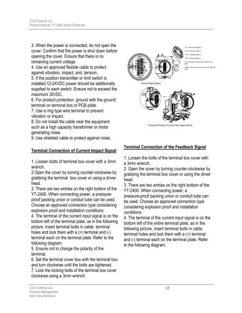
4. The terminal of the current input signal is on the<br />
bottom left of the terminal plate, as in the following<br />
picture. Insert terminal bolts in cable terminal<br />
holes and lock them with a (+) terminal and (-)<br />
terminal each on the terminal plate. Refer to the<br />
following diagram.<br />
5. Ensure not to change the polarity of the<br />
terminal.<br />
6. Set the terminal cover box with the terminal box<br />
and turn clockwise until the bolts are tightened.<br />
7. Lock the locking bolts of the terminal box cover<br />
clockwise using a 3mm wrench.<br />
<strong>CVS</strong> <strong>Controls</strong> Ltd.<br />
Process Management<br />
And Instrumentation<br />
Terminal Plate Position<br />
Terminal Connection of the Feedback Signal<br />
1. Loosen the bolts of the terminal box cover with<br />
a 3mm wrench.<br />
2. Open the cover by turning counter-clockwise by<br />
grabbing the terminal box cover or using the driver<br />
head.<br />
3. There are two entries on the right bottom of the<br />
YT-<strong>2400</strong>. When connecting power, a<br />
pressure-proof packing union or conduit tube can<br />
be used. Choose an approved connection type<br />
considering explosion proof and installation<br />
conditions.<br />
4. The terminal of the current input signal is on the<br />
bottom left of the entire terminal plate, as in the<br />
following picture. Insert terminal bolts in cable<br />
terminal holes and lock them with a (+) terminal<br />
and (-) terminal each on the terminal plate. Refer<br />
to the following diagram.<br />
12<br />
~ IN+: Current Input Signal (+)<br />
~ IN-: Current Input Signal (-)<br />
~ OUT+: Feedback Signal (+)<br />
~ OUT-: Feedback Signal (-)<br />
Connection Position of Current input signal terminal<br />
~ Top 3 terminals on second row : stroke 0% limit<br />
switch<br />
~Bottom 3 terminals on second row: stroke 100% limit<br />
switch