cvs 2400 series smart positioner product description - CVS Controls
cvs 2400 series smart positioner product description - CVS Controls
cvs 2400 series smart positioner product description - CVS Controls

Create successful ePaper yourself
Turn your PDF publications into a flip-book with our unique Google optimized e-Paper software.
<strong>CVS</strong> <strong>Controls</strong> Ltd.<br />
Product Manual: YT-<strong>2400</strong> Smart Positioner<br />
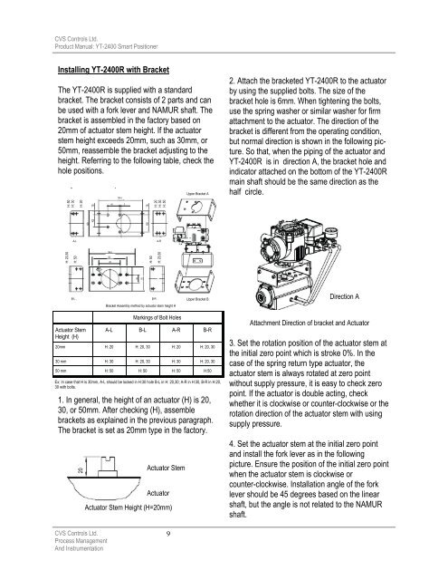
Installing YT-<strong>2400</strong>R with Bracket<br />
The YT-<strong>2400</strong>R is supplied with a standard<br />
bracket. The bracket consists of 2 parts and can<br />
be used with a fork lever and NAMUR shaft. The<br />
bracket is assembled in the factory based on<br />
20mm of actuator stem height. If the actuator<br />
stem height exceeds 20mm, such as 30mm, or<br />
50mm, reassemble the bracket adjusting to the<br />
height. Referring to the following table, check the<br />
hole positions.<br />
H: 50<br />
H: 30<br />
H: 20,30<br />
A-L<br />
H: 50<br />
B-L<br />
H: 20<br />
Actuator Stem<br />
Height (H)<br />
15<br />
90<br />
42<br />
1. In general, the height of an actuator (H) is 20,<br />
30, or 50mm. After checking (H), assemble<br />
brackets as explained in the previous paragraph.<br />
The bracket is set as 20mm type in the factory.<br />
<strong>CVS</strong> <strong>Controls</strong> Ltd.<br />
Process Management<br />
And Instrumentation<br />
165.6<br />
130<br />
80<br />
164.6<br />
45 5<br />
30<br />
90<br />
H: 20<br />
H: 30<br />
H: 50<br />
Actuator Stem<br />
Actuator<br />
Actuator Stem Height (H=20mm)<br />
15<br />
60<br />
H: 50<br />
B-R<br />
A-R<br />
H: 20,30<br />
Bracket Assembly method by actuator stem height H<br />
Markings of Bolt Holes<br />
9<br />
Upper Bracket A<br />
Upper Bracket B<br />
A-L B-L A-R B-R<br />
20mm H: 20 H: 20, 30 H: 20 H: 20, 30<br />
30 mm H: 30 H: 20, 30 H: 30 H: 20, 30<br />
50 mm H: 50 H: 50 H: 50 H:50<br />
Ex: In case that H is 30mm, A-L should be locked in H:30 hole B-L in H: 20,30; A-R in H:30, B-R in H:20,<br />
30 with bolts.<br />
20<br />
2. Attach the bracketed YT-<strong>2400</strong>R to the actuator<br />
by using the supplied bolts. The size of the<br />
bracket hole is 6mm. When tightening the bolts,<br />
use the spring washer or similar washer for firm<br />
attachment to the actuator. The direction of the<br />
bracket is different from the operating condition,<br />
but normal direction is shown in the following picture.<br />
So that, when the piping of the actuator and<br />
YT-<strong>2400</strong>R is in direction A, the bracket hole and<br />
indicator attached on the bottom of the YT-<strong>2400</strong>R<br />
main shaft should be the same direction as the<br />
half circle.<br />
Direction A<br />
Attachment Direction of bracket and Actuator<br />
3. Set the rotation position of the actuator stem at<br />
the initial zero point which is stroke 0%. In the<br />
case of the spring return type actuator, the<br />
actuator stem is always rotated at zero point<br />
without supply pressure, it is easy to check zero<br />
point. If the actuator is double acting, check<br />
whether it is clockwise or counter-clockwise or the<br />
rotation direction of the actuator stem with using<br />
supply pressure.<br />
4. Set the actuator stem at the initial zero point<br />
and install the fork lever as in the following<br />
picture. Ensure the position of the initial zero point<br />
when the actuator stem is clockwise or<br />
counter-clockwise. Installation angle of the fork<br />
lever should be 45 degrees based on the linear<br />
shaft, but the angle is not related to the NAMUR<br />
shaft.