cvs 2400 series smart positioner product description - CVS Controls
cvs 2400 series smart positioner product description - CVS Controls
cvs 2400 series smart positioner product description - CVS Controls

You also want an ePaper? Increase the reach of your titles
YUMPU automatically turns print PDFs into web optimized ePapers that Google loves.
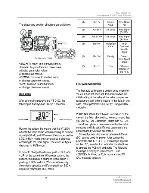
The shape and position of buttons are as follows:<br />
: To return to the previous menu<br />
: To go to the main menu, save<br />
adjusted parameter values<br />
or choose sub menus.<br />
: To move to another menu<br />
or change parameter values.<br />
: To move to another menu<br />
or change parameter values.<br />
Run Mode<br />
After connecting power to the YT-<strong>2400</strong>, the<br />
following is displayed on LCD in 6 seconds.<br />
Run Mode<br />
The Buttons of the YT-<strong>2400</strong><br />
Run on the bottom line means that the YT-<strong>2400</strong><br />
adjusts the valve stroke when receiving an outside<br />
signal (4-20mA) and PV means the number on the<br />
LCD. In RUN mode, the valve stroke is changed<br />
according to the input signal. There are six types<br />
displayed in RUN mode.<br />
In order to change the display, push and<br />
at the same time. Whenever pushing the<br />
buttons, the display is changed in that order. If<br />
pushing and simultaneously,<br />
the order is opposite and if only pushing ,<br />
display is returned to RUN mode.<br />
15<br />
PV<br />
Currently displayed on LCD<br />
First Auto Calibration<br />
<strong>CVS</strong> <strong>Controls</strong> Ltd.<br />
Product Manual: YT-<strong>2400</strong> Smart Positioner<br />
(1) Run PV Process<br />
Value<br />
Valve Stroke<br />
(%)<br />
(2) Run SV% Set Value Input Signal<br />
(0-100%)<br />
(3) Run SV mA Set Value Input Signal<br />
(4-20mA)<br />
(4) Run MV Manipulate<br />
Value<br />
Motor<br />
Controlled<br />
Variable<br />
(Digit)<br />
(5) Run Vel Velocity Current<br />
Valve Speed<br />
(Digit)<br />
(6) Run Err Error Difference<br />
between SV<br />
and PV %<br />
The first auto calibration is usually used when the<br />
YT-<strong>2400</strong> has not been set, this occurs when the<br />
initial setting of the valve at the valve company or<br />
replacement with other <strong>product</strong>s in the field. In this<br />
case, entire parameters are set by using AUTO2<br />
calibration.<br />
WARNING: When the YT-<strong>2400</strong> is installed on the<br />
valve in the field, after setting, we recommend that<br />
you use “AUTO1 Calibration” rather than AUTO2.<br />
This allows optimum parameters set by the valve<br />
company and it is better if those parameters are<br />
not changed by AUTO1 calibration.<br />
1. Connect power. Any values between 4-30mA<br />
(DC) can be used for power. After connecting<br />
power “READY 6, 5, 4, 3, 2, 1” message appears<br />
on the LCD, in order, that indicates the start time<br />
to operate the PCB unit and parts. The following<br />
message is displayed in 6 seconds. Push<br />
for 6 sec. at RUN mode and AUTO<br />
CAL message appears.<br />
<strong>CVS</strong> <strong>Controls</strong> Ltd.<br />
Process Management<br />
And Instrumentation